Table of Contents
Advertisement
Advertisement
Table of Contents

Related Manuals for Siemens 3RK1308‑0 00‑0CP0 Series


Summary of Contents for Siemens 3RK1308‑0 00‑0CP0 Series
- Page 1 Motor starter (3RK1308-0**00-0CP0)
- Page 3 Introduction Security information Information about third-party Industrial Controls software Product-specific safety instructions ET 200SP Motor starter Documentation guide (3RK1308‑0**00‑0CP0) Product features Equipment Manual Functions Parameters/address space Alarms/diagnostic messages Technical data CAx data Data sets Circuit examples 11/2019 A5E34821005002A/RS-AC/003...
- Page 4 Note the following: WARNING Siemens products may only be used for the applications described in the catalog and in the relevant technical documentation. If products and components from other manufacturers are used, these must be recommended or approved by Siemens. Proper transport, storage, installation, assembly, commissioning, operation and maintenance are required to ensure that the products operate safely and without any problems.
-
Page 5: Introduction
V1.0.0 or higher. This Equipment Manual supplements the ET 200SP System Manual (http://support.automation.siemens.com/WW/view/en/58649293). Functions affecting the system in general are described in the System Manual. There, you will also find information on installation, connection and the installation conditions of the ET 200SP motor starter. - Page 6 Siemens AG, its subsidiaries, and associated companies (hereinafter referred to as "Siemens") are not in a position to guarantee every characteristic of a complete plant or machine not designed by Siemens. Nor can Siemens assume liability for recommendations that appear or are implied in the following description.
- Page 7 Function blocks, background and system descriptions, performance statements, demonstration systems, and application examples, clearly explained and represented. ● Technical data Technical product data for support in planning and implementing your project. Link: Product support (https://support.industry.siemens.com/cs/ww/en/ps) Motor starter (3RK1308‑0**00‑0CP0) Equipment Manual, 11/2019, A5E34821005002A/RS-AC/003...
- Page 8 Introduction mySupport With "mySupport", your personal work area, you get the very best out of your Industry Online Support experience. Everything enables you to find the right information - every time. The following functions are now available: ● My notifications Your personal mailbox for exchanging information and managing your contacts ●...
- Page 9 Introduction Siemens Industry Online Support app You can use the Siemens Industry Online Support app to access all the device-specific information available on the Siemens Industry Online Support portal for a particular article number, including operating instructions, manuals, datasheets, FAQs etc.
- Page 10 Introduction Motor starter (3RK1308‑0**00‑0CP0) Equipment Manual, 11/2019, A5E34821005002A/RS-AC/003...
-
Page 11: Table Of Contents
Table of contents Introduction ............................. 5 Security information ..........................15 Information about third-party software ....................17 Product-specific safety instructions......................21 General safety notes ....................... 21 Safety information for hazardous areas .................. 22 Safety instructions for safety-related applications ..............23 Intended use ........................... 25 Current information about operational safety ................. - Page 12 Table of contents Calculating switching cycles ....................83 Substation monitoring ......................88 6.7.1 Response to residual current detection ................. 89 6.7.2 Upper/lower current warning limit ..................93 6.7.3 Upper/lower current limit ......................94 6.7.4 Blocking time and blocking current ..................95 6.7.5 Device protection model ......................
- Page 13 Status and error displays ...................... 161 TEST/RESET button ......................167 Interrupts ..........................168 Maintenance ......................... 170 Technical data ............................ 171 Technical data in Siemens Industry Online Support ............. 171 Final conditions for safety-related parameters ..............172 CAx data ............................. 173 10.1 CAx data ..........................173 Data sets ............................
- Page 14 Table of contents A.13 Read/write DS202 device parameter 2 ................196 A.14 Read DS203 device parameter 1..................197 A.15 Read DS204 device parameter 2..................200 A.16 I&M data ..........................201 A.16.1 I&M data ..........................201 A.16.2 I&M 0: Read device identification ..................202 A.16.3 I&M 1: Read/write equipment identifier ................
-
Page 15: Security Information
Siemens' products and solutions undergo continuous development to make them more secure. Siemens strongly recommends that product updates are applied as soon as they are available and that the latest product versions are used. Use of product versions that are no longer supported, and failure to apply the latest updates may increase customers' exposure to cyber threats. - Page 16 Security information Motor starter (3RK1308‑0**00‑0CP0) Equipment Manual, 11/2019, A5E34821005002A/RS-AC/003...
-
Page 17: Information About Third-Party Software
OSS licenses by contacting the following address. SIEMENS may charge a handling fee of up to 5 Euro to fulfil the request. Motor starter (3RK1308‑0**00‑0CP0) Equipment Manual, 11/2019, A5E34821005002A/RS-AC/003... - Page 18 Product or any OSS components contained in it if they are modified or used in any manner not specified by SIEMENS. The license conditions listed below may contain disclaimers that apply between you and the respective licensor.
- Page 19 Information about third-party software LICENSE CONDITIONS AND COPYRIGHT NOTICES Open Source Software: TivaWare Peripheral Driver Library - 2.1.4 Enclosed you'll find license conditions and copyright notices applicable for Open Source Software TivaWare Peripheral Driver Library - 2.1.4 License conditions: // Redistribution and use in source and binary forms, with or without // modification, are permitted provided that the following conditions // are met: // Redistributions of source code must retain the above copyright...
- Page 20 Information about third-party software Motor starter (3RK1308‑0**00‑0CP0) Equipment Manual, 11/2019, A5E34821005002A/RS-AC/003...
-
Page 21: Product-Specific Safety Instructions
Product-specific safety instructions General safety notes DANGER Hazardous voltage. Will cause death or serious injury. Turn off and lock out all power supplying this device before working on this device. NOTICE Damage caused by electrostatic charge The motor starter can become damaged by an electrostatic charge if the unoccupied pins of the motor starter are contacted. -
Page 22: Safety Information For Hazardous Areas
Product-specific safety instructions 3.2 Safety information for hazardous areas Safety information for hazardous areas WARNING Explosion hazard in Class I and Class II Hazardous Locations. Can cause death or serious injury. The fail-safe motor starter is permitted for the operation of device group II, Cat (2), area G D. -
Page 23: Safety Instructions For Safety-Related Applications
Product-specific safety instructions 3.3 Safety instructions for safety-related applications Safety instructions for safety-related applications WARNING Hazardous voltage. Will cause death or serious injury. To avoid an electric shock, observe the following safety measures when working on the plant and the device: •... - Page 24 Product-specific safety instructions 3.3 Safety instructions for safety-related applications WARNING Loss of the safety function with incorrect wiring If wiring is incorrect, the motor starter cannot shut down in the event of a fault and the motor will continue to run. There is a risk of severe injury or death. Material damage is also possible.
-
Page 25: Intended Use
Serious damage to property, can cause death or serious injury. This equipment is only allowed to be used for the applications described in the catalog and in the technical description, and only in conjunction with non-Siemens equipment and components recommended by Siemens. -
Page 26: Current Information About Operational Safety
By subscribing to the appropriate newsletter, you will ensure that you are always up-to-date and able to make changes to your system, when necessary: Newsletter (http://www.industry.siemens.com/newsletter) Sign on to the following newsletter under "Products & Solutions": ● Safety Integrated Newsletter ●... -
Page 27: Declaration Of Conformity
EC Directives stated (including amendments), and that the stated standards were applied in their design and construction. You can download the entire EC Declaration of Conformity: Declaration of Conformity (http://www.siemens.com/sirius/approvals). Standards The table below shows the standards that each of the ET 200SP motor starters comply with:... - Page 28 Product-specific safety instructions 3.6 Declaration of conformity Motor starter (3RK1308‑0**00‑0CP0) Equipment Manual, 11/2019, A5E34821005002A/RS-AC/003...
-
Page 29: Documentation Guide
Documentation guide The documentation for the SIMATIC ET 200SP distributed I/O system is arranged into three areas. This arrangement enables you to access the specific content you require. Basic information The System Manual and Getting Started describe in detail the configuration, installation, wiring and commissioning of the SIMATIC ET 200SP distributed I/O system. - Page 30 You must register once to use the full functionality of "mySupport". You can find "mySupport" on the Internet (https://support.industry.siemens.com/My/ww/en). "mySupport" - Documentation With "mySupport", your personal workspace, you make the best out of your Industry Online Support.
- Page 31 ● Manuals, characteristics, operating manuals, certificates ● Product master data You can find "mySupport" - CAx data on the Internet (http://support.industry.siemens.com/my/ww/en/CAxOnline). Application examples The application examples support you with various tools and examples for solving your automation tasks. Solutions are shown in interplay with multiple components in the system - separated from the focus on individual products.
- Page 32 You can find the SIMATIC Automation Tool on the Internet (https://support.industry.siemens.com/cs/ww/en/view/98161300). PRONETA SIEMENS PRONETA (PROFINET network analysis) allows you to analyze the plant network during commissioning. PRONETA features two core functions: ● The topology overview automatically scans the PROFINET and all connected components.
- Page 33 Documentation guide SINETPLAN SINETPLAN, the Siemens Network Planner, supports you in planning automation systems and networks based on PROFINET. The tool facilitates professional and predictive dimensioning of your PROFINET installation as early as in the planning stage. In addition, SINETPLAN supports you during network optimization and helps you to exploit network resources optimally and to plan reserves.
- Page 34 Documentation guide Motor starter (3RK1308‑0**00‑0CP0) Equipment Manual, 11/2019, A5E34821005002A/RS-AC/003...
-
Page 35: Product Features
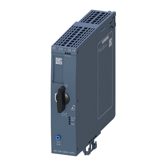
Product features Article numbers, properties, accessories Article numbers Short code Article number Direct-on-line starter DS 0.1 - 0.4 A HF 3RK1308-0AA00-0CP0 DS 0.3 - 1 A HF 3RK1308-0AB00-0CP0 DS 0.9 - 3 A HF 3RK1308-0AC00-0CP0 DS 2.8 - 9 A HF 3RK1308-0AD00-0CP0 DS 4.0 - 12 A HF including fan (3RW4928-8VB00) 3RK1308-0AE00-0CP0... - Page 36 Product features 5.1 Article numbers, properties, accessories Views of the ET 200SP motor starter The ET 200SP motor starter is a 30-mm-wide compact device with hybrid technology. The ET 200SP motor starter has electronic overload protection for switching of three-phase asynchronous motors and single-phase AC motors up to 5.5 kW (at 500 V) during normal operating conditions.
- Page 37 Product features 5.1 Article numbers, properties, accessories The figure below shows a fail-safe ET 200SP motor starter: Figure 5-2 View of the fail-safe ET 200SP motor starter with mounted 3DI/LC module (optionally available) Properties of the ET 200SP motor starter The ET 200SP motor starter has the following technical properties: ●...
- Page 38 ● Touch protection for infeed bus (3RK1908-1DA00-2BP0); is already provided with all BaseUnits with 500 V AC infeed You can find further information on accessories in the ET 200SP System Manual (https://support.industry.siemens.com/cs/ww/de/view/58649293/en?dl=en) in the Appendix "Accessories/spare parts". See also Introduction (Page 5) Motor starter (3RK1308‑0**00‑0CP0)
-
Page 39: Electromagnetic Compatibility
Product features 5.2 Electromagnetic compatibility Electromagnetic compatibility Definition of EMC Electromagnetic compatibility (EMC) is the ability of an electrical installation to function satisfactorily in its electromagnetic environment without interfering with that environment. Designing interference-free motor starters For interference-free operation of the ET 200SP station in accordance with standard IEC 60947-4-2, use a dummy module before the first motor starter. - Page 40 Product features 5.2 Electromagnetic compatibility Mounting the dummy module The figure below provides a schematic representation of how to implement measures for improving interference immunity. ① ⑥ Interface module Motor starter ② ⑦ Digital input module Motor starter ③ ⑧ Digital output module Server module ④...
-
Page 41: Designing Motor Starters In Conjunction With Electromechanical Switching Devices
Product features 5.3 Designing motor starters in conjunction with electromechanical switching devices Designing motor starters in conjunction with electromechanical switching devices NOTICE Use of motor starters in series with mechanical switching devices, e.g. line contactors When using motor starters in series with mechanical switching devices, e.g. line contactors, ensure that voltage peaks are prevented by means of the mechanical shutdown of small motors (high inductance). - Page 42 Product features 5.3 Designing motor starters in conjunction with electromechanical switching devices Remedial measures ● Delayed shutdown of the line contactor by the motor starter shutting down before the contact (in current zero point). These voltage peaks do not occur at all and the contactor can be shut down (de-energized) approx.
-
Page 43: Applications
Product features 5.4 Applications Applications You can use the ET 200SP motor starters wherever you want to switch and protect drives up to 5.5 kW with an ET 200SP system. The ET 200SP motor starters are used for the following, for example: ●... -
Page 44: Permissible Ambient Temperatures Up To 1000 M Above Sea Level
Product features 5.5 Permissible ambient temperatures up to 1000 m above sea level. Permissible ambient temperatures up to 1000 m above sea level. General supplementary conditions You can install the motor starter in two mounting positions: ● Horizontal mounting position ●... - Page 45 Product features 5.5 Permissible ambient temperatures up to 1000 m above sea level. Use of fans in group configuration (side-by-side) 1) Operation with power bus (24 V DC) up to 27 A See the table below for the cases in which you must use a fan depending on the ambient temperature when operating with a power bus (24 V DC) up to 27 A: Set operational Direct-on-line starter...
-
Page 46: Permissible Ambient Temperatures At More Than 1000 M Above Sea Level
Product features 5.6 Permissible ambient temperatures at more than 1000 m above sea level. Permissible ambient temperatures at more than 1000 m above sea level. Current derating as a function of the installation altitude is applicable for devices with and without fans. -
Page 47: Device Versions
• Maximum permissible current range of the motor starter: The permissible current range can be found in the graphic in Chapter "Device protection model (Page 95)". You will find more information on dimensioning switching devices for IE3/IE4 motors in the Switching devices application manual (http://support.automation.siemens.com/WW/view/en/94770820). Motor starter (3RK1308‑0**00‑0CP0) Equipment Manual, 11/2019, A5E34821005002A/RS-AC/003... -
Page 48: Operating Motor Starters
Product features 5.8 Operating motor starters Operating motor starters Hardware and software requirements Fail-safe ET 200SP motor starters are supported by IM155-6PN BA interface modules with firmware V3.2 or higher, IM155-6PN ST with firmware V3.1 or higher, IM155-6PN HF with firmware V3.1 or higher and IM155-6DP HF with firmware V3.0 or higher. - Page 49 Product features 5.8 Operating motor starters The switching on and off routines must be run through without errors. This means: ● Current must flow. ● The motor starter must not display any errors. ● The supply voltage must be stable. The switching on or off routine is canceled as soon as an error is detected.
- Page 50 If your equipment makes it necessary to protect the contact against overvoltage, you have to connect the F-DI input of the BU-30-MS5 to BU-30-MS10 BaseUnits to surge filters! Refer to Chapter "Electromagnetic compatibility" in ET 200SP System Manual (https://support.industry.siemens.com/cs/ww/de/view/58649293/en?dl=en). WARNING Safety-related shutdown via the F-DI...
- Page 51 Product features 5.8 Operating motor starters Bright and dark tests With bright and dark tests, safety relays such as ET 200SP F-PM-E (6ES7136-6PA00-0BC0) or SIRIUS 3SK check whether their safe outputs can still be activated and deactivated. The bright and dark tests are run cyclically. The ET 200SP motor starter is intended for operation with an F-PM-E or 3SK connected upstream and is adapted to the bright and dark test times of these devices.
- Page 52 General information on the dimensioning of SITOP power supplies when ET 200SP motor starters are used can be found in Industry Online Support under FAQ ET 200SP motor starter (https://support.industry.siemens.com/cs/ww/en/ps/21800/faq). Peak current in the electric torque Number of motor starters...
- Page 53 Product features 5.8 Operating motor starters Number of motor starters Current in A Time in ms (until 8 A rated current is reached) 5.00 6.90 9.00 Figure 5-4 Peak current in the electric torque Connecting and operating motor brakes ET 200SP motor starters can be operated for the following braking applications: ●...
- Page 54 Product features 5.8 Operating motor starters Response to asymmetry: You use this device parameter to determine the behavior of the motor starter in the event of asymmetry: ● Warning (not permissible for fail-safe motor starters in ATEX operation) ● Shutdown Note Using brake motors When using brake motors, you have to increase the set rated motor current by the braking...
- Page 55 Product features 5.8 Operating motor starters Variant 2. High Feature DOL starter or reversing starter with 230 V brake The current for the braking device is drawn from only one switched phase. Connection is via The single-phase connection of the motor brake leads to phase asymmetry at the motor connection.
- Page 56 Product features 5.8 Operating motor starters Figure 5-6 Connection of a 230 V brake with connection to the neutral conductor to an ET 200SP motor starter Motor starter (3RK1308‑0**00‑0CP0) Equipment Manual, 11/2019, A5E34821005002A/RS-AC/003...
- Page 57 Product features 5.8 Operating motor starters Variant 3. High Feature DOL starter or reversing starter and F DOL starter or F reversing starter with 230 V brake without connection to the neutral conductor The current for the braking device is drawn from only one switched phase. Connection is via T1.
- Page 58 Product features 5.8 Operating motor starters Figure 5-7 Connection of a 230 V brake in star connection and connection to the neutral point on an ET 200SP motor starter Motor starter (3RK1308‑0**00‑0CP0) Equipment Manual, 11/2019, A5E34821005002A/RS-AC/003...
- Page 59 Product features 5.8 Operating motor starters Overview The table below shows which motor starters can be operated with which of the three variants (✓ = permissible; - = not permissible): Version 400 V brake 230 V brake with connection 230 V brake with connection to the neutral conductor to the neutral point Motor connection...
- Page 60 ● Motor starting current + brake inrush current: 19.6 A + 4 A = 23.6 A ● Maximum current-carrying capacity of 3 A motor starter (3RK1308 - 0AC00-0CP0): 30 A; see also data sheet (https://support.industry.siemens.com/cs/ww/en/ps/21800/faq (https://support.industry.siemens.com/cs/ww/en/ps/21800/faq)) ● Result: The maximum current-carrying capacity is 23.6 A. It is below 30 A for this application.
- Page 61 Product features 5.8 Operating motor starters ATEX-certified motor overload protection ET 200SP fail-safe motor starters are approved under device group II, Category 2) in the "GD" area. This means that the fail-safe motor starters can protect motors that are located in hazardous gas, vapor, mist and air mixtures and also combustible dust.
- Page 62 Product features 5.8 Operating motor starters Motor starter (3RK1308‑0**00‑0CP0) Equipment Manual, 11/2019, A5E34821005002A/RS-AC/003...
-
Page 63: Functions
Functions Overview of functions The table below shows the functions of the various versions of ET 200SP motor starters: Direct-on-line Reversing starter Fail-safe Fail-safe starter direct-on-line reversing starter starter Basic function/basic parameter (Page 67) Rated operational current (Page 67) • Load type (Page 69) •... - Page 64 Functions 6.1 Overview of functions Direct-on-line Reversing starter Fail-safe Fail-safe starter direct-on-line reversing starter starter Response to CPU/master STOP (Page 102) Group fault diagnostics/group warning diagnostics (Page 103) TEST/RESET button (Page 167) Emergency start (Page 118) (Not with an (Not with an ATEX application) ATEX application) Trip RESET (Page 125)
- Page 65 Functions 6.1 Overview of functions Direct-on-line Reversing starter Fail-safe Fail-safe starter direct-on-line reversing starter starter Operational trip end position CW (Page 127) Operational trip end position CCW (Page 128) 1) From FW Version 1.2.0 The following functions are safety-related: Fail-safe Fail-safe reversing direct-on-line starter starter...
-
Page 66: Intrinsic Protection
Functions 6.2 Intrinsic protection Intrinsic protection The ET 200SP motor starter protects itself against overload. Intrinsic device protection cannot be parameterized or switched off. You can find more information on the permissible ambient temperatures in chapter Permissible ambient temperatures up to 1000 m above sea level. -
Page 67: Basic Function/Basic Parameter
Functions 6.3 Basic function/basic parameter Basic function/basic parameter 6.3.1 Basic functions/parameters during first commissioning The default settings listed in the following two chapters apply to first commissioning and as defaults for the programming devices (exception: rated operational current). When a motor starter is set to the commissioning mode again, it uses the values that were valid when the technology supply voltage was last lost. - Page 68 Functions 6.3 Basic function/basic parameter Current motor current The latest current in the motor starter is returned via the process image for analysis. In addition, you can read out the latest current with phase precision in data set 94. The current is measured in two phases. The current for the third phase is calculated. The highest of the three values is determined.
-
Page 69: Load Type
Functions 6.3 Basic function/basic parameter 6.3.3 Load type This is where you select whether the motor starter should protect a single-phase or a three-phase load. Note Reversing starter 1-phase loads are not permissible on the reversing starter. 1-phase operation is also not permissible after activation of the "EX motor"... -
Page 70: Motor Control
Functions 6.4 Motor control Motor control 6.4.1 Electronic switching technology (hybrid switching technology) The ET 200SP motor starter combines the advantages of semiconductor technology and relay technology. The ET 200SP motor starter switches the load in phases L1 and L2 via semiconductors and bypass relays. - Page 71 The ET 200SP motor starters do not possess any galvanic isolation of the switching elements in the main circuits. The isolating function in compliance with EN 60947-1 is only warranted in the parking position. See also ET 200SP System Manual (http://support.automation.siemens.com/WW/view/en/58649293) Motor starter (3RK1308‑0**00‑0CP0) Equipment Manual, 11/2019, A5E34821005002A/RS-AC/003...
-
Page 72: Minimum Load Current
Functions 6.4 Motor control 6.4.2 Minimum load current The minimum load current is 20% of the set motor current, but at least the absolute minimum current specified in the tables below. The minimum load current differs between the ET 200SP motor starters and the fail-safe ET 200SP motor starters: Load current 0.1 …... -
Page 73: Control Function
Functions 6.4 Motor control 6.4.3 Control function The motor starter controls the direction of rotation of motors with the control function. Internal logic prevents you from activating both directions of rotation simultaneously. The graphic below shows the reaction times of the motor starter to control commands. The reaction times when restarting and changing direction of rotation are identical. -
Page 74: Operating Modes
Functions 6.4 Motor control Interlock time: 150 ms + 5 ms time slice run ON-delay Fail-safe motor starters: 25 ms • HF motor starter: 20 ms • Recovery time t Fail-safe motor starters: t + 210 ms • HF motor starter: t0 + 190 ms •... - Page 75 Functions 6.4 Motor control Figure 6-4 Operating modes 1) possible as of firmware version 1.2.0 Motor starter (3RK1308‑0**00‑0CP0) Equipment Manual, 11/2019, A5E34821005002A/RS-AC/003...
-
Page 76: Overload Protection
Functions 6.5 Overload protection Overload protection Description The approximate temperature of the motor is calculated using the measured motor currents and device parameters "Rated operating current" and "Tripping class". This indicates whether the motor is overloaded or is functioning in the normal operating range. CAUTION Ensuring overload protection Do not connect more than one motor to one motor starter to ensure overload protection. - Page 77 Functions 6.5 Overload protection Principle of operation The electronics continuously calculate a model of the thermal load on the motor dependent on the operating time and the current load. The motor memory model charges when the motor is switched on. The motor memory model discharges after the motor is switched off. Figure 6-5 Principle of operation Following an overload tripping operation, the motor memory model is fully discharged after...
- Page 78 Functions 6.5 Overload protection Response to overload - thermal motor model You use this device parameter to specify how the motor starter is to respond to overload: ● Trip without restart ● Trip with restart WARNING Hazardous Voltage. Can Cause Death, Serious Injury, or Property Damage. When the cooling time has expired following an overload trip, and a RESET takes place, or automatic restart has been parameterized, the machine starts up immediately if a control command is active.
- Page 79 Functions 6.5 Overload protection Trip class The trip class (CLASS) specifies the maximum time within which a protective device must trip from a cold state at 7.2 x the setting current (motor protection to IEC 60947-2). The tripping characteristics represent the time to trip as a function of the current multiple. The continuous black line in the following diagrams illustrates the tripping characteristic curve for three-pole symmetrical loads and for single-phase loads.
- Page 80 Functions 6.5 Overload protection The following diagram shows the overload protection for CLASS 5: Figure 6-7 CLASS 5 overload protection Motor starter (3RK1308‑0**00‑0CP0) Equipment Manual, 11/2019, A5E34821005002A/RS-AC/003...
- Page 81 Functions 6.5 Overload protection The following diagram shows the overload protection for CLASS 10: Figure 6-8 CLASS 10 overload protection You can find out how to calculate the switching cycles in chapter Calculating switching cycles (Page 83). Motor starter (3RK1308‑0**00‑0CP0) Equipment Manual, 11/2019, A5E34821005002A/RS-AC/003...
- Page 82 Functions 6.5 Overload protection The following trip classes can be parameterized according to IEC 60947-4-2: ● CLASS OFF ● CLASS 5 (10 A) ● CLASS 10 To protect the switching elements in the main circuit against impermissible operating states, an integrated intrinsic device protection is provided in the upper load range. At overload currents greater than 65 A, shutdown becomes effective earlier than with the motor protection function (intrinsic device protection model).
-
Page 83: Calculating Switching Cycles
Functions 6.6 Calculating switching cycles Calculating switching cycles The switching cycles attainable by the ET200 SP motor starter are determined by the root-mean-square of the motor current l . The switching cycle considered is admissible rms_motor if the following criterion is met: ≤... - Page 84 Functions 6.6 Calculating switching cycles Motor starter (3RK1308‑0**00‑0CP0) Equipment Manual, 11/2019, A5E34821005002A/RS-AC/003...
- Page 85 Functions 6.6 Calculating switching cycles Switching cycle parameters The following table shows all the parameters that you have to consider for calculation of the permissible switching cycle: Parameters Description Conditions Starting time Time during which the motor The maximum is determined by the Startup accelerates up to its operating parameterized tripping class and the intrinsic...
- Page 86 Functions 6.6 Calculating switching cycles As from a starting current of 65 A in the case of the 9 A and 12 A motor starters, consider the device protection model for calculation of the switching cycles. The following graphics show the minimum idle time depending on the starting current: Minimum idle time (T ) 9 A motor starter at I...
- Page 87 Functions 6.6 Calculating switching cycles Example for the minimum idle time (T ) 12 A motor starter at I Startup/ rated The graphic below shows the minimum idle time of a 12 A motor starter with the following parameters: = 10.4 A rated_motor = 8.6;...
-
Page 88: Substation Monitoring
Functions 6.7 Substation monitoring Substation monitoring You can determine various system states with the help of the motor current and the current limits. System state Current value Protection by: Motor operates more sluggishly, Current is higher than normal Upper current limit e. -
Page 89: Response To Residual Current Detection
Functions 6.7 Substation monitoring 6.7.1 Response to residual current detection If the motor current drops to under 20% from the set operational current or below the minimum load limit in one of the phases, residual current detection responds. You use this device parameter to specify how the motor starter is to behave in the event of residual current being detected: ●... - Page 90 Functions 6.7 Substation monitoring Residual current detection for motor starters with 0.9 ... 3 A The following graphic shows the dependence of residual current detection on the set motor current in the case of motor starters with 0.9 to 3 A: Figure 6-11 Residual current detection 0.9-3 A device Residual current detection for motor starters with 2.8 ...
- Page 91 Functions 6.7 Substation monitoring Residual current detection for fail-safe motor starters with 0.1 ... 0.4 A The following graphic shows the dependence of residual current detection on the set motor current in the case of motor starters with 0.1 to 0.4 A: Figure 6-14 Residual current detection 0.1-0.4 A device Residual current detection for fail-safe motor starters with 0.3 ...
- Page 92 Functions 6.7 Substation monitoring Residual current detection for fail-safe motor starters with 2.8 ... 9 A The following graphic shows the dependence of residual current detection on the set motor current in the case of motor starters with 2.8 to 9 A: Figure 6-17 Residual current detection 2.8-9 A device Residual current detection in the case of fail-safe motor starters with 4 ...
-
Page 93: Upper/Lower Current Warning Limit
Functions 6.7 Substation monitoring 6.7.2 Upper/lower current warning limit You can enter an upper and/or a lower current warning limit value. If the current warning values are exceeded or undershot, the motor starter responds with a warning message without tripping. The warning message is acknowledged as soon as the warning threshold is exceeded or undershot by 5%. -
Page 94: Upper/Lower Current Limit
Functions 6.7 Substation monitoring 6.7.3 Upper/lower current limit You can enter an upper and/or a lower current limit. The current limits are deactivated by default. If the current limits are overshot or undershot, the motor starter responds by tripping. The "I upper limit value violation"... -
Page 95: Blocking Time And Blocking Current
Functions 6.7 Substation monitoring 6.7.4 Blocking time and blocking current The blocking current specifies how much current is consumed by the motor (at rated voltage) when the drive is blocked. If the motor current exceeds 400 % of the set motor current I for a time >... - Page 96 Functions 6.7 Substation monitoring The motor starter operates within a permissible current range. The following graphic shows the permissible current range: Figure 6-19 Device protection Motor starter (3RK1308‑0**00‑0CP0) Equipment Manual, 11/2019, A5E34821005002A/RS-AC/003...
- Page 97 Functions 6.7 Substation monitoring How the motor starter's device protection works is described below. Shutting down the motor starter within the permissible current range The motor starter switches off in the following cases: ● The motor starter is too hot. ●...
-
Page 98: Temperature Monitoring
Functions 6.7 Substation monitoring 6.7.6 Temperature monitoring The motor starter has an internal temperature monitoring function. If the motor starter exceeds its internal temperature warning threshold, the "Switching element hot" alarm is issued in data set 75 (Page 184). The motor starter switches off if the temperature continues to rise. -
Page 99: Short-Circuit Protection (Fuses)
Functions 6.7 Substation monitoring Settings Table 6- 4 Settings for asymmetry monitoring Device parameters Default setting Setting range Response to asymmetry Tripping Warn • Tripping • 6.7.8 Short-circuit protection (fuses) Description The ET 200SP motor starter is equipped with integrated safety fuses as short-circuit protection. -
Page 100: Safety-Related Functions
Functions 6.8 Safety-related functions Safety-related functions 6.8.1 Self-test ET 200SP fail-safe motor starters run a self-test of the switching elements every time they are switched on and off. Ensure a stable line power supply. An unstable power supply may lead to a situation in which the motor starter incorrectly signals a fault. -
Page 101: Ex Motor Application
Functions 6.8 Safety-related functions 6.8.3 Ex motor application Set the "Ex motor application" parameter if the fail-safe motor starter is to switch and protect an explosion-proof motor. Note ATEX Ex II (2) G D zones You can use the fail-safe motor starter for explosion-proof motors that are situated in ATEX Ex II (2) G D zones. -
Page 102: Response To Cpu/Master Stop
Functions 6.9 Response to CPU/master STOP Response to CPU/master STOP With this parameter, you set the response of the PIQ following a CPU STOP: ● Retain last value The last received and valid value of the process image of the outputs is retained. ●... -
Page 103: Group Fault Diagnostics/Group Warning Diagnostics
CPU. If you set the group warning diagnostics parameter to "Disable", no maintenance alarms are output. You will find the requirements for the use of maintenance alarms in an Maintenance FAQ (https://support.industry.siemens.com/cs/ww/en/view/109485777). Settings Table 6- 7 Settings for group fault/group warning diagnostics... -
Page 104: Inputs
For information on this topic, see Chapter "Connecting the 3DI/LC module for the motor starter" in the ET 200SP System Manual (https://support.industry.siemens.com/cs/ww/de/view/58649293/en?dl=en). Inputs for commissioning To ensure operation of a motor in the unparameterized state of the ET 200SP motor starter... - Page 105 Functions 6.11 Inputs Response to removal of the 3DI/LC module: Bit 2.5 is reset in the process image input if you remove the 3DI/LC module during operation. You can evaluate the bit and thus indicate unintentional removal. The inputs are not open-circuit-proof.
- Page 106 Functions 6.11 Inputs Note Change from NC contact to NO contact If "Input n level" is changed from a normally closed contact to a normally open contact and the associated "Input n action" is parameterized as "Trip without restart", the "Input tripping" message bit is set and shut down accordingly in the case of an open input due to the input delay! Note...
- Page 107 Functions 6.11 Inputs Table 6- 8 Input n action Input Input n level Input n signal Operating Description n action mode No action NO/NC n. ret./ret. No direct action on the motor starter. Evaluation und further processing possible using the process image.
- Page 108 Functions 6.11 Inputs Input Input n level Input n signal Operating Description n action mode Motor CW n. ret./ret. Manual local The motor starter must be in "manual local" • mode mode for these actions. Motor CCW (with reversing Motor CW: Switching the motor on or off •...
- Page 109 Functions 6.11 Inputs Input Input n level Input n signal Operating Description n action mode Operational trip end NO/NC n. ret. The motor is tripped regardless of the direction position CCW of rotation (CW or CCW). The motor can only be switched on with •...
- Page 110 Functions 6.11 Inputs Settings Table 6- 9 Settings for inputs Device parameters Default setting Setting range Input signal delay 10 ms • Input 1 level NO contact NC contact • • Input 2 level NO contact • Input 3 level Input 1 action Motor CW No action...
-
Page 111: Manual Local (Local Control)
Functions 6.12 Manual local (local control) 6.12 Manual local (local control) Manual local control with the ET 200SP motor starter is only possible when the 3DI/LC module is inserted. A digital input is permanently assigned the function "Manual local" (LC connection). -
Page 112: Trip Without Restart
Functions 6.13 Trip without restart 6.13 Trip without restart The action "Trip without restart" results in the following behavior: ● The motor is tripped. Acknowledge disconnection via Trip Reset after remedying the cause of tripping. You can then switch on the motor again. ●... -
Page 113: Trip With Restart
Functions 6.14 Trip with restart 6.14 Trip with restart The action "Trip with restart" results in the following behavior: ● The motor is tripped. ● Acknowledged automatically after the cause of the trip has been rectified (input status). ● The parameter can only be implemented as "non-retentive". ●... -
Page 114: Trip Emergency End Position Cw
Functions 6.15 Trip emergency end position CW 6.15 Trip emergency end position CW If the motor control command is not equal to "Motor OFF", the diagnostic interrupt "Trip end position CW responded" incoming is triggered when a 0 → 1 edge is detected at the digital input. - Page 115 Functions 6.15 Trip emergency end position CW Example The following example shows the "trip end position CW" with digital input 1 parameterized to "Trip end position CW": Figure 6-20 Example of trip end position CW ① You switch the motor on by means of "Motor CW". The motor is running. ②...
-
Page 116: Trip Emergency End Position Ccw
Functions 6.16 Trip emergency end position CCW 6.16 Trip emergency end position CCW If the motor control command is not equal to "Motor OFF", the diagnostic interrupt "Trip end position CCW responded" incoming is triggered when a 0 → 1 edge is detected at the digital input. -
Page 117: Group Warning
Functions 6.17 Group warning 6.17 Group warning The action "Group warning" results in the following behavior: ● A "group warning" is generated. ● An entry with the object number 304 (byte 0, bit 7) is generated in the DS92 Read device diagnostics (Page 186). -
Page 118: Emergency Start
Functions 6.18 Emergency start 6.18 Emergency start Description Emergency start enables restart despite an internal trip command. Emergency start is possible if there is an ON switching command for the motor. The motor is switched on despite a pending trip cause. At a limit trip, the motor starts in the opposite direction. Emergency starting is not possible in the following situations: ●... -
Page 119: Motor Cw
Functions 6.19 Motor CW 6.19 Motor CW In automatic mode, the motor is activated or deactivated in the CW direction with the aid of the process image of the outputs. If you would like to control the motor via the 3DI/LC module, activate the LC input on the 3DI/LC module (manual local mode). -
Page 120: Motor Ccw
Functions 6.20 Motor CCW 6.20 Motor CCW In automatic mode, the motor is activated or deactivated in the CCW direction with the aid of the process image of the outputs. If you would like to control the motor via the 3DI/LC module, activate the LC input on the 3DI/LC module (manual local mode). -
Page 121: Quick Stop Direction-Independent
Functions 6.21 Quick Stop direction-independent 6.21 Quick Stop direction-independent ● Motor is tripped without group fault. ● "Quick Stop" takes priority over "Motor CW" and "Motor CCW" ● The input action responds to the active edge of the input signal, which means that deactivation is possible when the static input signal "Quick stop"... - Page 122 Functions 6.21 Quick Stop direction-independent Example 2: Input 1 signal = non-retentive ① The motor is switched on and off by "Motor CW". ② The motor is switched on by "Motor CW", then switched off by the level at digital input 1 (parameterized with input action 1 = Quick Stop).
-
Page 123: Quick Stop Clockwise
Functions 6.22 Quick Stop clockwise 6.22 Quick Stop clockwise The action "Quick Stop CW" results in the following behavior: ● The motor is switched off with pending signal "Motor CW" without group fault ● The motor is not switched off with pending signal "Motor CCW" ●... -
Page 124: Quick Stop Counter-Clockwise
Functions 6.23 Quick Stop counter-clockwise 6.23 Quick Stop counter-clockwise The action "Quick Stop CCW" results in the following behavior: ● The motor is switched off with pending signal "Motor CCW" without group fault ● The motor is not switched off with pending signal "Motor CW" ●... -
Page 125: Trip Reset
Functions 6.24 Trip RESET 6.24 Trip RESET "Trip RESET" acknowledges all the errors/faults that are currently active and that can be acknowledged. An error/fault can be acknowledged if its cause has been rectified or if it is no longer present. Trip RESET is triggered by: ●... -
Page 126: Cold Start
Functions 6.25 Cold start 6.25 Cold start Description The "cold start" function enables control of a motor without error messages. The motor starter responds here as if the main power supply were connected to the system. Thus, in the commissioning phase, for example, the relevant control commands are accepted from the controller and the relevant messages are sent. -
Page 127: Operational Trip End Position Cw
Functions 6.26 Operational trip end position CW 6.26 Operational trip end position CW If the motor control command is not equal to "Motor OFF", an operational trip of the motor is triggered when a signal change at the operational trip end position CW DI is detected. This motor tripping triggered by the operational trip end position is revoked by the motor control command "Motor OFF". -
Page 128: Operational Trip End Position Ccw
Functions 6.27 Operational trip end position CCW 6.27 Operational trip end position CCW If the motor control command is not equal to "Motor OFF", an operational trip of the motor is triggered when a signal change at the operational trip end position CCW DI is detected. This motor tripping triggered by the operational trip end position is revoked by the motor control command "Motor OFF". -
Page 129: Logbook
Functions 6.28 Logbook 6.28 Logbook Description The logbooks contain a chronological list of device faults, trips and events that are assigned a time stamp, thus creating a log. The log is stored internally so that the causes can be evaluated at a later stage. Logbooks Three logbooks that can be read as a data set are available: ●... -
Page 130: Profienergy
Using PROFIenergy with the ET 200SP motor starter SIEMENS provides two function blocks for using PROFIenergy: ● PE_START_END (FB815) supports the switch to an energy-saving mode. ● PE_CMD (FB816) supports the reading out of measured values and the switch to an energy-saving mode You will find further information in the document entitled "Common Application Profile... - Page 131 Functions 6.29 PROFIenergy Commands The following tables show the supported commands: Control commands Start_Pause The starter switches to energy-saving mode. Start_Pause_with_time_response The starter switches to energy-saving mode and signals its minimum idle times. End_Pause The starter switches back to operating mode. Status commands PE_Identify Provides a list of supported PROFIenergy commands/functions.
- Page 132 Functions 6.29 PROFIenergy Time_to_Pause Time the starter requires in order to change to energy saving mode. With the ET 200SP motor starter, this time is always 100 ms. Time_min_length_of_stay Minimum time that the device spends or should spend in off_min saving mode.
- Page 133 The switch to energy-saving mode is recorded in the "Events" logbook. Entry: "Energy saving mode active" See also Application example (https://support.industry.siemens.com/cs/ww/en/view/109478388) PROFINET system description (http://support.automation.siemens.com/WW/view/en/19292127) Motor starter (3RK1308‑0**00‑0CP0) Equipment Manual, 11/2019, A5E34821005002A/RS-AC/003...
-
Page 134: Firmware Update
You update the firmware of the motor starter with the help of firmware files. Note Note the preconditions for a firmware update/downgrade You can find the preconditions for a firmware update/downgrade in the Siemens Industry Online Support under the entry Firmware update for ET 200SP motor starter (https://support.industry.siemens.com/cs/ww/en/view/109486088). - Page 135 Functions 6.30 Firmware update Figure 6-22 Selecting the software downloads ● Before installing the firmware update, make sure that the modules are not being used. NOTICE Firmware update for fail-safe motor starters In the case of fail-safe motor starters, the firmware update is permissible only if the motor starter is the only module on a rack.
- Page 136 Functions 6.30 Firmware update Note Securing the supply voltage On starting, and during the firmware update, the 24 V DC supply voltage must be applied at the header module and the motor starter. Note Interrupted firmware update If a firmware update has been interrupted, remove and reconnect the affected module before a renewed firmware update.
- Page 137 SIMATIC memory card. 5. Insert the SIMATIC memory card containing the firmware update files in the CPU. Procedure using the Web server The procedure is described in the Function Manual Web server (http://support.automation.siemens.com/WW/view/en/59193560). Motor starter (3RK1308‑0**00‑0CP0) Equipment Manual, 11/2019, A5E34821005002A/RS-AC/003...
- Page 138 Functions 6.30 Firmware update Behavior during the firmware update Note the following behavior during the firmware update of the motor starter: ● The LEDs flash as described in chapter "Status and error displays (Page 161)". ● The motor starter powers up again after completion of the firmware update. Diagnoses are reset.
-
Page 139: Parameters/Address Space
ET 200SP motor starters. Note List of supported ET 200SP header modules You will find a list of the compatible ET 200SP header modules in the Siemens Industry Online Support (https://support.industry.siemens.com/cs/ww/en/view/109485777). Note Reduction to default parameters In the following cases, the full scope of parameterization is reduced by the configuring software to the standard parameters (DS201) for system reasons: •... - Page 140 Parameters/address space 7.1 Parameter assignment Parameters for ET 200SP motor starter The effective range of the adjustable parameters depends on the type of configuration. The following configurations are possible: ● Centralized operation with an ET 200SP CPU and the ET 200SP Open Controller ●...
-
Page 141: Commissioning Mode
Parameters/address space 7.2 Commissioning mode Commissioning mode Commissioning mode is available for fail-safe ET 200SP motor starters. When setting up a system, you can test the wiring without the functioning PROFINET or PROFIBUS connection. Perform the test in commissioning mode. The motor starter switches to commissioning mode in the following cases: ●... -
Page 142: Parameterization Using A Gsd File
Parameters/address space 7.3 Parameterization using a GSD file Parameterization using a GSD file For the ET 200SP-IM155 interface module of the ET 200SP system, there are two different GSD files, one for operation with PROFINET and one for operation with PROFIBUS. The GSD and GSDML files can be used with STEP 7 V5.5 SP4 and higher, and TIA Portal V13 SP1 and higher. -
Page 143: Slot Rules
Parameters/address space 7.4 Slot rules Slot rules You can find further information on the structure of a system with an ET 200SP motor starter in the ET 200SP System Manual (http://support.automation.siemens.com/WW/view/en/58649293). Motor starter (3RK1308‑0**00‑0CP0) Equipment Manual, 11/2019, A5E34821005002A/RS-AC/003... -
Page 144: Data Plausibility Check
Parameters/address space 7.5 Data plausibility check Data plausibility check Check of the incoming parameters in the "Automatic" and "Manual bus" modes The motor starter checks all incoming parameters for validity and plausibility, provided manual local mode is not active. The valid parameters are stored in data set 203 and 204. In the case of incorrect parameters during startup (after power ON): ●... - Page 145 Parameters/address space 7.5 Data plausibility check Checking incoming parameters in "Manual local" mode The incoming parameters are checked as follows in "Manual local" mode: ● When the motor is switched off: The motor starter saves the parameter and accepts it only when the motor starter has switched over to "Automatic"...
-
Page 146: Declaration Of Parameters
Parameters/address space 7.6 Declaration of parameters Declaration of parameters Trip class The trip class (CLASS) specifies the maximum time within which a protective device must trip from a cold state at 7.2x the setting current (motor protection to IEC 60947). For more information, see Chapter Overload protection (Page 76). - Page 147 Parameters/address space 7.6 Declaration of parameters Input n signal You use this device parameter to determine whether or not the input level of the digital inputs is to be saved. For more information, see Chapter Inputs (Page 104). Load type Here, you can specify whether the motor starter must protect a 1-phase load (direct-on-line starters only) or a 3-phase load.
- Page 148 Parameters/address space 7.6 Declaration of parameters Thermal motor model (response to overload) You use this device parameter to determine how the motor starter is to respond to overload. For more information, see Chapter Overload protection (Page 76). Response to CPU/master STOP Determines the module's response to CPU STOP.
-
Page 149: Assigning Fail-Safe Motor Starter Parameters
Parameters/address space 7.7 Assigning fail-safe motor starter parameters Assigning fail-safe motor starter parameters 7.7.1 Explanation of safety-related parameters Ex motor The motor starter can switch and protect loads in an EX protection zone (see Ex motor application (Page 101)). Response to safety-related tripping The motor starter can send a warning to the CPU if tripping has been triggered through the fail-safe input (see Response to safety-related tripping (Page 100)). - Page 150 Parameters/address space 7.7 Assigning fail-safe motor starter parameters ● Manual local mode The motor starter accepts the new parameters and saves them. As soon as manual local mode is ended, the parameters are activated and indicated by means of the LEDs' flashing sequence.
-
Page 151: Configuring Atex Operation
Parameters/address space 7.7 Assigning fail-safe motor starter parameters 7.7.3 Configuring ATEX operation ET 200SP fail-safe motor starters protect motors in an ATEX environment. The following parameters are considered to be safety-related in ATEX operation: ● Rated operational current (I ● Trip class You set the parameters via the data sets or using the engineering software. - Page 152 Parameters/address space 7.7 Assigning fail-safe motor starter parameters LED flashing sequence The following graphic shows the order in which the LEDs flash: Figure 7-1 Flashing sequence during ATEX operation Motor starter (3RK1308‑0**00‑0CP0) Equipment Manual, 11/2019, A5E34821005002A/RS-AC/003...
- Page 153 Parameters/address space 7.7 Assigning fail-safe motor starter parameters The start of the flashing sequence is indicated by the "MAN", "F-DI" and "ST/OL" LEDs, which light up briefly in green all at the same time. The multi-colored LEDs then light up in red and yellow.
-
Page 154: Examples Of Led Flashing Sequences
Parameters/address space 7.7 Assigning fail-safe motor starter parameters 7.7.4 Examples of LED flashing sequences Below you see a few examples of the LED flashing sequence. Example of I = 5 A and CLASS 10 The following figure shows the LED flashing sequence with a fail-safe motor starter that has trip class I = 5 A and CLASS 10: Figure 7-2... - Page 155 Parameters/address space 7.7 Assigning fail-safe motor starter parameters Example of I = 0.34 A and CLASS 5 The following figure shows the LED flashing sequence with a fail-safe motor starter that has trip class I = 0.34 A and CLASS 5: Figure 7-3 Display example I = 0.34 A CLASS 5...
- Page 156 Parameters/address space 7.7 Assigning fail-safe motor starter parameters Example of I = 11.4 A and CLASS 5 The following figure shows the LED flashing sequence with a fail-safe motor starter that has trip class I = 11.4 A and CLASS 5: Figure 7-4 Display example 11.4 A CLASS 5 Example of I...
- Page 157 Parameters/address space 7.7 Assigning fail-safe motor starter parameters ATEX off display The following figure shows the LED flashing sequence when ATEX operation for a fail-safe motor starter is deactivated: Figure 7-6 ATEX off display Motor starter (3RK1308‑0**00‑0CP0) Equipment Manual, 11/2019, A5E34821005002A/RS-AC/003...
-
Page 158: Address Space
Parameters/address space 7.8 Address space Address space Process image of the outputs Table 7- 1 Contents of process image of the outputs (in bytes 0 to 1) Process data Meaning Relevant for DQ 0.0 Motor CW DQ 0.1 Motor CCW Reversing starters only DQ 0.2 DQ 0.3... - Page 159 Parameters/address space 7.8 Address space Process image of the inputs Table 7- 2 Process image of the inputs (in bytes 0 to 3) Process data Meaning Relevant for DI 0.0 Ready (automatic) DI 0.1 Motor ON DI 0.2 Group fault DI 0.3 Group warning DI 0.4...
- Page 160 Parameters/address space 7.8 Address space Motor starter (3RK1308‑0**00‑0CP0) Equipment Manual, 11/2019, A5E34821005002A/RS-AC/003...
-
Page 161: Alarms/Diagnostic Messages
Alarms/diagnostic messages Status and error displays LED display The figure below shows the LED display on the ET 200SP motor starter: ① (green) - Run ② (red) - Error ③ (yellow) - Maintenance ④ ST/OL (red/green) - State/overload ⑤ (yellow) - Manual (manual local mode) ⑥... - Page 162 Alarms/diagnostic messages 8.1 Status and error displays The figure below shows the LED display on the fail-safe ET 200SP motor starter: ① (green) - Run ② (red) - Error ③ (yellow) - Maintenance ④ ST/OL (red/green) - State/overload ⑤ (yellow) - Manual (manual local mode) ⑥...
- Page 163 Alarms/diagnostic messages 8.1 Status and error displays Meaning of the LEDs The tables below give the meanings of the status and fault displays: RN/ER/MT LED Table 8- 1 RN/ER/MT status and error displays LEDs Meaning Explanation (RUN) (ERROR) (MAINT) Operating state "RUN", the ET 200SP relevant relevant motor starter is in a "normal"...
- Page 164 Alarms/diagnostic messages 8.1 Status and error displays LEDs Meaning Explanation (RUN) (ERROR) (MAINT) Error Group fault relevant relevant Flashes At least one Error alarm has been at ≥ 2 Hz transferred to the controller. Possible causes: Electronics supply voltage too low or •...
- Page 165 Alarms/diagnostic messages 8.1 Status and error displays MAN (MANUAL) LED Table 8- 3 Status display MAN MAN LED Meaning Remedy Manual local mode deactivated Manual local mode activated Connection abort in manual bus mode Flashes at 1 Hz PWR (POWER) LED Table 8- 4 Status display PWR PWR LED...
- Page 166 Alarms/diagnostic messages 8.1 Status and error displays LED combinations Table 8- 6 Status displays ST/OL/MAN/PWR LEDs Meaning Explanation ST/OL (Manual) (Power) (State/ Overload) LED/fan test All LEDs are switched on for 4 s (triggered by pressing the blue button). Lights up Lights up Lights up for 4 s...
-
Page 167: Test/Reset Button
Alarms/diagnostic messages 8.2 TEST/RESET button TEST/RESET button The RESET button has the following functions: Designation Tripping Description LED/fan test Press of a The LED/fan test is activated. All LEDs (ST/OL, MAN, PWR) light up and the fan button for less is switched on for 4 s. -
Page 168: Interrupts
Alarms/diagnostic messages 8.3 Interrupts Interrupts The ET 200SP motor starter supports diagnostic interrupts and maintenance. You can read out the diagnoses of the motor starter in the following data sets: ● DS72 logbook - Read device error (Page 180) ● DS73 logbook - Read triggering operations (Page 182) ●... - Page 169 Alarms/diagnostic messages 8.3 Interrupts Error type Fault text Remedial measures channel diagnostics 1083 (4227 Switching element Switching element (switching contact, power semiconductor) too hot. overload Check the ambient conditions linked to cooling. You might have to take derating into consideration. Check the number of switching operations. Also check whether the fan is working properly.
-
Page 170: Maintenance
You will find general information on extended maintenance in "Diagnostics" in the SIMATIC PROFINET Function Manual (https://support.industry.siemens.com/cs/de/de/view/49948856/en). The PROFINET interfaces of the interface module support the diagnostics concept and maintenance concept in PROFINET according to the standard IEC 61158-6-10. The aim is early detection and correction of potential faults. -
Page 171: Technical Data
Technical data in Siemens Industry Online Support Technical data sheet You can also find the technical data of the product at Siemens Industry Online Support (https://support.industry.siemens.com/cs/ww/en/ps/). 1. Enter the full article number of the desired device in the "Product" field, and confirm with the Enter key. -
Page 172: Final Conditions For Safety-Related Parameters
Technical data 9.2 Final conditions for safety-related parameters Final conditions for safety-related parameters Safety-related parameters The safety-related parameters in the data sheet have been determined on the basis of the following final conditions: ● Side-by-side mounting at rated current I ●... -
Page 173: Cax Data
CAx data 10.1 CAx data You can find the CAx data in the Siemens Industry Online Support (https://support.industry.siemens.com/cs/ww/en/ps/). 1. Enter the full article number of the desired device in the "Product" field, and confirm with the Enter key. 2. Click the "CAx data link. - Page 174 CAx data 10.1 CAx data Motor starter (3RK1308‑0**00‑0CP0) Equipment Manual, 11/2019, A5E34821005002A/RS-AC/003...
-
Page 175: Data Sets
Data sets Reading and writing of data records You can access the data sets of the motor starter from STEP 7: ● Writing data sets by calling SFB 53 "WRREC" ● Reading data sets by calling SFB 52 "RDREC" You will find further information about the SFB in the STEP 7 online help. Motor starter (3RK1308‑0**00‑0CP0) Equipment Manual, 11/2019, A5E34821005002A/RS-AC/003... -
Page 176: Byte Arrangements
Data sets A.2 Byte arrangements Byte arrangements When data longer than one byte is stored, the bytes are arranged as follows ("big endian"): Motor starter (3RK1308‑0**00‑0CP0) Equipment Manual, 11/2019, A5E34821005002A/RS-AC/003... -
Page 177: Ds68 Read/Write Process Image Output
Data sets A.3 DS68 Read/write process image output DS68 Read/write process image output Note Please note that data set 68 is overwritten by the cyclic process image in automatic mode! Byte Content Value / value range Meaning Coordination 0x21 Write via acyclic bus channel (PLC) Reserved 0x00 Reserved... -
Page 178: Ds69 Read Process Image Input
Data sets A.4 DS69 Read process image input DS69 Read process image input Byte Content Value / value range Meaning Process data DI 0.0 to DI 0.7 See table below Process data DI 1.0 to DI 1.7 See table below Process data DI 2.0 to DI 2.7 See table below... - Page 179 Data sets A.4 DS69 Read process image input Byte.Bit Encoding Process data Meaning Relevant for Bit (1 = active) DI 2.0 Ready to start for motor ON DI 2.1 Motor CW DI 2.2 Motor CCW Reversing starters only DI 2.3 Quick stop active DI 2.4 Energy saving mode active...
-
Page 180: Ds72 Logbook - Read Device Error
Data sets A.5 DS72 logbook - Read device error DS72 logbook - Read device error Byte Data type Meaning Range of values Increment Entry 1 (= latest entry) 0 … 3 Unsigned 32 Operating hours - device 0 … 2 4 …... - Page 181 Data sets A.5 DS72 logbook - Read device error Table A- 3 Assignment of object number to device error message Object No. Device fault messages Fail-safe motor starter defective 308 Switching element defective 381 Error during self-test 417 Stack overflow 418 Stack underflow 423 Invalid command 434 Error in system software...
-
Page 182: Ds73 Logbook - Read Triggering Operations
Data sets A.6 DS73 logbook - Read triggering operations DS73 logbook - Read triggering operations Byte Data type Meaning Range of values Increment Entry 1 (latest entry) 0 ... 3 Unsigned 32 Operating hours - device 0 … 2 4 ... 5 Signed 16 Object number 0 …... - Page 183 Data sets A.6 DS73 logbook - Read triggering operations The supported object numbers and their meaning are shown in the table below: Table A- 4 Assignment of object number to trips message Object No. Trips message Comment 305 Safety-related tripping Fail-safe motor starters only 309 Switching element overload 317 Electronics supply voltage too low...
-
Page 184: Ds75 Logbook - Read Events
Data sets A.7 DS75 logbook - Read events DS75 logbook - Read events Byte Data type Meaning Range of values Increment User data (technology data) Entry 1 (latest entry) 0 ... 3 Unsigned 32 Operating hours - device 0 … 2 4 ... - Page 185 Data sets A.7 DS75 logbook - Read events The supported object numbers and their meaning are shown in the table below: Table A- 5 Assignment of object number to event message Object No. Event messages Comment Warnings 327 Thermal motor model overload In the case of a group fault, the message "Motor overload trip"...
-
Page 186: Ds92 Read Device Diagnostics
Data sets A.8 DS92 Read device diagnostics DS92 Read device diagnostics Object Byte.Bit Meaning Relevant for number User data (technology data) Switching/controlling 301 0.0 Ready (automatic) The device is ready for operation via the controller. There is no connection to the mechanical rotary interlock. 306 0.1 Motor CW 307 0.2... - Page 187 Data sets A.8 DS92 Read device diagnostics Object Byte.Bit Meaning Relevant for number 350 5.7 Input trip CCW - 6.0-1 Reserved 353 6.2 Quick stop active 354 6.3 Sensor supply overload - 6.4-6 Reserved 317 6.7 Electronics supply voltage too low Communication - 7.0 Reserved...
- Page 188 Data sets A.8 DS92 Read device diagnostics Object Byte.Bit Meaning Relevant for number - 19.4-7 Reserved 1422 20.0 Thermal motor model deactivated - 21.0-1 Reserved Protection function 1482 21.2 Current measuring range overshot - 21.3-7 Reserved Communication (operating modes) 357 22.0 Automatic mode (redundant to bit 7.2) - 22.1-2 Manual bus mode (redundant to bit 7.3)
- Page 189 Data sets A.8 DS92 Read device diagnostics Object Byte.Bit Meaning Relevant for number Warnings - 52.0-3 Reserved 1541 52.4 warning limit exceeded 1542 52.5 warning limit undershot - 52.6-7 Reserved - 53 Reserved Motor starter (3RK1308‑0**00‑0CP0) Equipment Manual, 11/2019, A5E34821005002A/RS-AC/003...
-
Page 190: Ds93 Write Command
Data sets A.9 DS93 Write command DS93 Write command Write structure of data set 93 command Byte Content Value / value range Meaning 0 Coordination 0x31 Write via acyclic bus channel 1 Reserved 0x00 2 Reserved 0x00 3 Reserved 0x00 Command 4 Number of 1 ... -
Page 191: Ds94 Read Measured Values
Data sets A.10 DS94 Read measured values A.10 DS94 Read measured values Object Byte.Bit Coding Meaning Range of Increment number values User data (technology data) Measured values (volatile) 504 0 Unsigned 8 Phase current I 0 ... 796 % 3.125 % L1(%) 505 1 Unsigned 8... -
Page 192: Ds95 Read Statistics
Data sets A.11 DS95 Read statistics A.11 DS95 Read statistics Object Byte.Bit Coding Meaning Range of Increment number values User data (technology data) Reserved - 1.0-5 Reserved - 1.6-7 Bit 6 operating hours resolution 11 (fixed) 1 second Bit 7 operating hours selection 1 operating hour - device - 2 ... -
Page 193: Read/Write Ds201 Device Parameter 1
Data sets A.12 Read/write DS201 device parameter 1 A.12 Read/write DS201 device parameter 1 DS201 contains the second part of the device parameters. If incorrect parameters are sent to the motor starter in DS201, these incorrect parameters will also be reported back when reading DS201. In the case of incorrect parameters, the object number of the first incorrect parameter is output in WORD 10 of DS92. - Page 194 Data sets A.12 Read/write DS201 device parameter 1 Object Byte.Bit Range of values Meaning See Chapter ... number 20 1.6 [0]: Warning (not Response to asymmetry Asymmetry monitoring (Page 98) during ATEX operation) [1]: Tripping 317 1.7 Diagnosis Supply [0] released (default) Diagnosis supply voltage voltage too low [1] block...
- Page 195 Data sets A.12 Read/write DS201 device parameter 1 Object Byte.Bit Range of values Meaning See Chapter ... number 194 3 [0]: No action Input 1 action Inputs (Page 104) [1]: Trip without restart [2]: Trip with restart [3]: Trip end position [4]: Trip end position [5]: Group warning [7]: Emergency start...
-
Page 196: Read/Write Ds202 Device Parameter 2
Data sets A.13 Read/write DS202 device parameter 2 A.13 Read/write DS202 device parameter 2 DS202 contains the second part of the device parameters. If incorrect parameters are sent to the motor starter in DS202, these incorrect parameters will also be reported back when reading DS202. In the case of incorrect parameters, the object number of the first incorrect parameter is output in WORD 10 of DS92. -
Page 197: Read Ds203 Device Parameter 1
Data sets A.14 Read DS203 device parameter 1 A.14 Read DS203 device parameter 1 DS203 contains the second part of the incorrect parameter with which the motor starter is working. The defaults appear in italics in the Value range column. Object Byte.Bit Range of values Meaning... - Page 198 Data sets A.14 Read DS203 device parameter 1 Object Byte.Bit Range of values Meaning See Chapter ... number 25 2.0 [0]: NC contact Input 1 level Inputs (Page 104) [1]: NO contact 27 2.1 See input 1 level Input 2 level Inputs (Page 104) 29 2.2 See input 1 level...
- Page 199 Data sets A.14 Read DS203 device parameter 1 Object Byte.Bit Range of values Meaning See Chapter ... number 15 8 18.75 … 100 %/3.125 % Lower current limit Upper/lower current limit (Page 94) [6 … 32] [0]: Deactivated 16 9 50 …...
-
Page 200: Read Ds204 Device Parameter 2
Data sets A.15 Read DS204 device parameter 2 A.15 Read DS204 device parameter 2 DS204 contains the second part of the incorrect parameters with which the motor starter is working. The defaults appear in italics in the Value range column. Object Byte.Bit Range of values... -
Page 201: I&M Data
Data sets A.16 I&M data A.16 I&M data A.16.1 I&M data The following I&M data (Identification & Maintenance function) are supported by all ET 200SP motor starters: Number Name Comment I&M 0 Device identification This is stored in the device on initialization I&M 1 Equipment identifier These are entered in the engineering system. -
Page 202: I&M 0: Read Device Identification
Block length = 56 4 ... 5 Unsigned16 0x0100 Block version = 1.0 I&M0 data block 0 6 ... 7 Unsigned16 MANUFACTURER_ID 42 = Manufacturer ID SIEMENS 8 ... 27 Char[20] ORDER_ID Article number (MLFB) 28 ... 43 Char[16] SERIAL_NUMBER Serial number 44 ... -
Page 203: I&M 1: Read/Write Equipment Identifier
Data sets A.16 I&M data A.16.3 I&M 1: Read/write equipment identifier The following data are saved: Byte Length Content Meaning I&M header 0 ... 1 Unsigned16 0x0021 Block type 2 ... 3 Unsigned16 0x0038 Block length = 56 4 ... 5 Unsigned16 0x0100 Block version = 1.0... - Page 204 Data sets A.16 I&M data Motor starter (3RK1308‑0**00‑0CP0) Equipment Manual, 11/2019, A5E34821005002A/RS-AC/003...
-
Page 205: Circuit Examples
Circuit examples Connection examples for motor starters B.1.1 Connecting and operating motor brakes See Chapter Operating motor starters (Page 48). B.1.2 Example of the correct engineering of a motor starter See Chapter Operating motor starters (Page 48). Motor starter (3RK1308‑0**00‑0CP0) Equipment Manual, 11/2019, A5E34821005002A/RS-AC/003... -
Page 206: Induction Machine
Circuit examples B.1 Connection examples for motor starters B.1.3 Induction machine Direct-on-line starter Article numbers: ● BaseUnit: 3RK1908-0AP00-0AP0 ● Motor starter: 3RK1308-0A*00-0CP0 Reversing starter Article numbers: ● BaseUnit: 3RK1908-0AP00-0AP0 ● Motor starter: 3RK1308-0B*00-0CP0 In the multi-pole representation, the N and PE conductors are not shown separately. Do not connect PE or N to the neutral point. -
Page 207: Single-Phase Motor
Circuit examples B.1 Connection examples for motor starters B.1.4 Single-phase motor Article numbers: ● BaseUnit: 3RK1908-0AP00-0AP0 ● Motor starters: 3RK1308-0A*00-0CP0 In the multi-pole representation, the PE conductor is not shown separately. Motor starter (3RK1308‑0**00‑0CP0) Equipment Manual, 11/2019, A5E34821005002A/RS-AC/003... -
Page 208: Resistive Load
Circuit examples B.1 Connection examples for motor starters B.1.5 Resistive load Star connection Article numbers: ● BaseUnit: 3RK1908-0AP00-0AP0 ● Motor starters: 3RK1308-0A*00-0CP0 Delta connection: Article numbers: ● BaseUnit: 3RK1908-0AP00-0AP0 ● Motor starters: 3RK1308-0A*00-0CP0 Do not connect PE or N to the neutral point. In the multi-pole representation, the N and PE conductors are not shown separately. -
Page 209: Gas Discharge Lamps
Circuit examples B.1 Connection examples for motor starters B.1.6 Gas discharge lamps Article numbers: ● BaseUnit: 3RK1908-0AP00-0AP0 ● Motor starters: 3RK1308-0A*00-0CP0 In the multi-pole representation, the PE conductor is not shown separately. Note Motor model und response to overload of the gas discharge lamp Observe the set motor model and the overload response of the gas discharge lamp for the parameterization of the motor starter. -
Page 210: Connection Examples For Fail-Safe Motor Starters
Documentation and sample projects You will find an entry Safe shutdown of ET 200SP motor starters (https://support.industry.siemens.com/cs/ww/en/view/109748128) in the Industry Online Support. This entry describes methods of switching off one or more ET 200SP F motor starters in a safety-oriented manner. -
Page 211: Safety-Related Shutdown
Circuit examples B.2 Connection examples for fail-safe motor starters B.2.2 Safety-related shutdown Single shutdown With the BaseUnits BU30-MS5 to BU30-MS6, a single shutdown can be implemented with the aid of the F-DI. Single shutdown in SIL3 Cat. 4 PL e is possible here with fail-safe control modules with pp-switching or pm-switching. - Page 212 Circuit examples B.2 Connection examples for fail-safe motor starters Group shutdown With the BaseUnits BU30-MS7 to BU30-MS10, a group shutdown can be implemented with the aid of the F-DI. The group shutdown in SIL3 Cat 4 PL e is only possible with fail-safe control modules with pp-switching.
-
Page 213: Connecting The 3Di/Lc Module For The Motor Starter
Circuit examples B.2 Connection examples for fail-safe motor starters B.2.3 Connecting the 3DI/LC module for the motor starter Procedure The figure below shows the connections of the 3DI/LC module: ① Digital input 3 ② Digital input 2 ③ Digital input 1 ④... - Page 214 Circuit examples B.2 Connection examples for fail-safe motor starters Terminal sketch of the 3DI/LC module The following diagram shows a terminal sketch of the 3DI/LC module: Figure B-1 Connection example of inputs Motor starter (3RK1308‑0**00‑0CP0) Equipment Manual, 11/2019, A5E34821005002A/RS-AC/003...
-
Page 215: Index
Diagnosis Electronics supply voltage too low, 146 Dimension drawings, 8 Dummy module Mounting, 40 Accessories of the ET 200SP motor starter, 38 Siemens Industry Online Support, 9 Applications, 43 Article numbers, 35 Electromagnetic compatibility (EMC), 39 Assignment of object number to device error... - Page 216 Index High Feature DOL starter or reversing starter and F DOL starter or F reversing starter with 400 V brake, 53 Parameter, 140 High Feature DOL starter or reversing starter with Parameter assignment, 139 230 V brake, 53 Parameterization with the PROFIBUS GSD file, 142 Parameterization with the PROFINET GSDML file, 142 Permissible ambient temperatures at more than 1000 m above sea level., 46...
- Page 217 Index Safety instructions for safety-related applications, 24 Safety notes for hazardous areas, 22 Safety-related parameters, 172 Safety-related tripping, 100 Self-test, 100 Slot rules, 143 Standards, 27 Support Request, 9 Switching cycle parameters, 85 Temperature monitoring, 98 Thermal motor model (response to overload), 148 Third-party software information, 17 Trip class, 146 Trip emergency end position CCW, 116...
- Page 218 Index Motor starter (3RK1308‑0**00‑0CP0) Equipment Manual, 11/2019, A5E34821005002A/RS-AC/003...