
Related Manuals for Mitsubishi Electric PLK-G2008H


Summary of Contents for Mitsubishi Electric PLK-G2008H
- Page 1 INDUSTRIAL SEWING MACHINE MODEL PLK-G2008H TECHNICAL MANUAL SEWING MACHINE HEAD A180E674P04...
- Page 2 FOR SAFE USE Before the installation, operation, and inspection for this product, read the “FOR SAFE USE” and the technical manuals carefully. Also read the other technical manuals, “Control Unit” and “Operation Panel” describing some instructions, which are not in this manual, and use the sewing machine properly. SAFETY INDICATIONS Indicates that incorrect handling may cause hazardous conditions, resulting DANGER...
- Page 3 SAFETY PRECAUTIONS DANGER To prevent from receiving an electric shock, always turn off a power switch and unplug power supply when opening a control box, and then open after ten minutes passes. CAUTION USAGE ENVIRONMENT Please do not operate the sewing machine under the following conditions. (1) In the ambient temperature of 35 degrees (95°F) or more than 35 degrees, or the ambient temperature of 5 degrees or less than 5 degrees (41°F).
- Page 4 (9) Please make sure to fit the safety protective equipment (the motor cover or the others) and the accessory protective equipment (the eye guard) that removed temporarily for installation. (10) If the table and the steel stand are not MITSUBISHI original, the table and the steel stand have to be strong enough to withstand the weight and vibration of the sewing machine.
-
Page 5: Table Of Contents
CONTENTS 1. STRUCTURE OF THE SEWING MACHINE···································· 2. SPECIFICATION······································································· 3. INSTALLATION········································································ 3-1. Preparation of the table·········································································· 3-2. Preparation of the steel stand·································································· 3-3. Installation of the motor·········································································· 3-4. Installation of the control box··································································· 3-5. Connection of the operation panel···························································· 3-6. Installation of the power switch································································ 3-7. - Page 6 6. SEWING················································································· 6-1. The sewing operation············································································ 6-2. Operation of the halt switch····································································· 6-3. The teaching operation·········································································· 6-4. Pre-heating control················································································ 6-5. Setting of the Left / right alternating clamp specification································· 6-5-1. Setting of the clamp priority order························································· 6-5-2. Setting of the method of the clamp up for the step clamp movement············ 6-5-3.
- Page 7 7-14. Adjustment of the position detecting disc·················································· 7-15. The relation of the hook position and upper stop position····························· 7-16. Adjustment of the mechanical home position············································· 7-16-1. Adjustment of the X direction···························································· 7-16-2. Adjustment of the Y direction···························································· 7-17. Adjustment of the X-Y drive timing belt tension·········································· 7-17-1.
-
Page 8: Structure Of The Sewing Machine
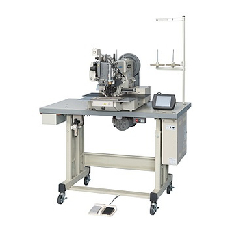
1. STRUCTURE OF THE SEWING MACHINE PLK-G2008H electronic pattern sewing machine consists of the following main parts. <3> <9> <1> <5> <11> <10> <2> <8> <4> <6> <7> <1>: Sewing machine head <2>: Main motor <3>: Halt switch <4>: Control box <5>: Operation panel <6>: Work holder foot switch <7>: Start foot switch <8>: Steel stand... -
Page 9: Specification
2. SPECIFICATIONS Model : PLK-G2008H Sewing area : X-direction (left/right) 200 mm, Y-direction (front / back) 80 mm Maximum sewing speed : 700 rpm Setting speed : 10 speed levels in 200 rpm to 700 rpm Stitch length : 0.1 to 20.0 mm... -
Page 10: Installation
3. INSTALLATION CAUTION (1) Please have some specialists, who have enough experience for the sewing machine installations, install the sewing machine. (2) Please have a Qualified Electrician perform necessary electric wiring. (3) Please do not operate until the sewing machine is repaired when any damage or fault is found on the sewing machine at the installation. -
Page 11: Installation Of The Power Switch
3-6. Installation of the power switch (1) Mount the power switch (No.1) with the wood screw (No.2) underneath the table as shown on the figure. (2) Fix the electric cords with the staples (No.3) underneath the table. (3) Hook up the connector of the power switch (No1) to the connector of the cable (No.4). (4) Hook up the connector of the cable (No.4) to the CON B connector of the control box (No.6). -
Page 12: Installation Of The Oil Pan
3-8. Installation of the oil pan (1) Assemble the oil pan (No.1) and oil bottle (No.2) which are enclosed in the accessory box. (2) Insert the oil bottle (No.2) into the table top cut-out hole. (3) Install the oil pan (No.1) fit with the table front edge. (4) Fix the oil pan (No.1) at its four corners on the table top with four staples (No.3) en-closed in the accessory box. -
Page 13: Installation Of The V-Belt
(No.4). [Notice] About the motor pulley (No.3) it is necessary to use only PLK-G2008H accessory. Other motor pulley for the PLK-E1008H/2008H and PLK-B1008H are different in size. Please do not use that kind of motor pulleys. - Page 14 (3) Fix the X-Y spindle motor cable (No.6) with the nylon clip (No.8) on the sewing machine head which enclosed in the X-Y spindle motor cable set. (4) Hold the dangling cables under the table with accessory tie holders (No.9) and cord ties (No.10). At this time, please check whether the cables are not pulled when tilting the sewing machine.
-
Page 15: Installation Of The Belt Cover
3-12. Installation of the belt cover (1) Attach the belt cover mounting plate (No.1, 2) to the sewing machine head with the set screws (No.3). (2) Put the belt cover (NO.4) on to the mounting plate with set screws (No.5). 3-13. -
Page 16: Connection Of The Air Tube
3-14. Connection of the air tube (1) Remove the spindle motor cover. (2) Attach the air pressure regulator assembly (No.1) underneath the table with the wood screws (No.2). These are enclosed in the accessory box. There are pilot holes for the wood screw on the undersurface of the table.. -
Page 17: Lubrication
4. LUBRICATION CAUTION (1) Please make sure to turn power switch off before lubricating. (2) Please pay attention that oil does not get on your skin or in your eyes as it may cause an inflammation. (3) Please make sure to keep oil out of the reach of children who may drink oil by mistake. [Notice] Please make sure to lubricate when operating for the first time after the installation. -
Page 18: Proper Operation
5. PROPER OPERATION 5-1. Initial setting of the control box When using the sewing machine for the first time, the model and the language of the sewing machine in use have to be set. Refer to the instructions in the paragraph “[6] Initial Setting of System (Model/language Setting)” in the CONTROL UNIT technical manual. - Page 19 (4) The screen to select the step file is displayed. Please choose the [2008HT * * ] by using up and down arrow button. (The * * mark displays file version.) [Notice] Please make sure that the file name [2008HT * * ] is selected correctly. If you 2 0 0 8 H T * * are set in different file names, it may cause a malfunction.
-
Page 20: How To Create A Usb Memory For Initial Configuration
(8) Initial condition Message "M-006:PATTERN DATA DOES NOT EXIST" appears, press , please switch to the standard screen. ― ― ― ― ― ― ― ― (It does not appear when the sewing data is ― ― ― stored.) 5-2-2. How to create a USB memory for initial configuration If the USB memory that came with is no longer available in the loss, etc., please create a USB memory for initial configuration in the following manner. - Page 21 (4) Click the “System Copy” button. Data copy will be executed. (5) When copying is complete, the message will be appeared, then click OK button. Press button to close the window. (6) The setting table copy to USB memory is completed. Please confirm the content of USB memory.
-
Page 22: Installation Of The Needle
5-3. Installation of the needle CAUTION (1) Please make sure to turn the power switch off before installing or replacing needles. (2) Please pay attention for the fingers not to be injured by the needle point. (1) Loosen the set screw (No.1) then, insert a new needle (No.2) until the needle head is reached the end of the hole of the needle bar (No.3). -
Page 23: Threading The Upper Thread
5-4. Threading the upper thread CAUTION (1) Please turn the power switch off when threading a needle. Thread the upper thread as shown on the figure. When the oil tank is used Wind on a wheel - 16 -... -
Page 24: Winding The Bobbin Thread
5-5. Winding the bobbin thread CAUTION Please do not touch the rotating part during winding thread. Doing so may cause injury and/or the machine failure. [Notice] Please make sure to pull the upper thread out of the needle before winding the bobbin thread. (1) Route the thread as shown in the below figure then, wind the thread to the bobbin (No.1) in the direction of “A”... -
Page 25: Setting The Bobbin
5-6. Setting the bobbin 5-6-1. Taking out the bobbin (1) As shown below, press the bobbin removal lever (No.1) found at the right side of the hook to the right. The bobbin case (No.3) will open, and the bobbin (No.2) can be removed from the case. NOTE If the bobbin case does not open even when the lever is pressed to the right, adjust the lever stroke by adjusting screw (No.9) or the bobbin's position must be rotated. -
Page 26: Sewing
6. SEWING CAUTION (1) Before starting the sewing, please make sure the position and the function of the halt switch. (2) Please do not touch the operating parts during sewing operation. (3) It is very dangerous to operate the sewing machine without safety guards (eye guards, belt covers, link covers, or the others). -
Page 27: The Teaching Operation
6-3. The teaching operation Detail descriptions for pattern input are mentioned in TECHNICAL MANUAL <Operation Panel Section>. As for the input method of PLK-G2008H, it is necessary to operate the peculiarity compared with other PLK machines. Peculiar point is STOP code [USTP] just after TRIM code is required for thermal trimming sequence. -
Page 28: Pre-Heating Control
6-4. Pre-heating control To secure the trimming, it is available to use pre-heating by input Function Code No.4 FUN4 in the pattern data. Relationship between FUN4 and pre-heating behavior is described as below. Heater-on ex. (1) Pattern data: Heater-on ex. (2) Pattern data: Heater-on Heater-on ex. -
Page 29: Setting Of The Method Of The Clamp Up For The Step Clamp Movement
(5) Set the clamp priority order. Press the [Priority of clamp mode]. (6) Change the priority order invalid display on the screen to valid , and press (7) Press the on the screen. (8) Then screen return to the [Mode Selection]. Press the Clamp priority order setting has completed. -
Page 30: The Thermal Trimming Operation
6-6. The thermal trimming operation There are 2 operation switches for thermal trimming operation. <2> <1>: Automatic (normal mode) and Manual (test mode) <1> conversion switch. <2>: Thermal thread trimming device (needle and bobbin thread / invalid / bobbin thread) conversion switch. -
Page 31: Adjustment Of The Thread Tension
6-7. Adjustment of the thread tension The thread tension between the upper and bobbin thread should be balanced in the best condition. When the upper thread tension is well balanced with the bobbin thread tension, the both threads are interlocked along the center line of fabric layers as shown on the below figures. NOTE Normally weaker bobbin thread tension bring better sewing quality. -
Page 32: Standard Adjustment
7. STANDARD ADJUSTMENT CAUTION (1) Please make sure to turn the power switch off before adjusting the sewing machine. (2) When adjusting the sewing machine with the power switch on, please be careful not to step on the foot switch by mistake. (3) Please be careful not to be injured by a sharp part such as the needle and the shuttle hook point. -
Page 33: Adjustment Of The Needle Bar Height
(4) Loosen screw (No.5). (5) Loosen screw (No.6), and adjust so that marker dot (No.3) engraved on the eccentric cam of the vertical rod is aligned with marker line (No.4) engraved on the main shaft. (6) After the adjustment, securely tighten screws (No.5 and 6). <4>... -
Page 34: Adjustment Of The Needle To Shuttle Clearance
7-4. Adjustment of the needle-to shuttle clearance Correct clearance between the recess in the needle (No.1) and the blade point of the shuttle (No.2) is 0.25 ~ 0.35 mm. To adjust the needle-to-shuttle clearance, (1) Loosen screw (No.3). (2) Adjust the clearance by moving shuttle driving shaft bushing (No.4) to the left and right. (3) After adjustment has been completed, tighten screw (No.3) firmly. -
Page 35: Test Mode Operation
7-6. Test mode operation 7-6-1. Entrance for the test mode operation The test mode operation is used for adjustment of mechanical position (height or stroke) for the thermal thread trimmer equipment and also for check the position of the sensors of the cylinders. For entrance this mode, (1) Turn the power switch ON. -
Page 36: Key Function In The Test Mode
7-6-2. Key function in the test mode In the test mode, each key on the operation panel works to operate the thermal thread trimmer equipment (cylinders or relay) independently. Relationship between the key and the equipment is as below. In the Test mode, Start switch is disabled. [01111] is displayed during automatic operation [01111] is displayed during manual operation [01111] is displayed when the "Return"... - Page 37 Needle tread trimmer function Needle thread trimmer return (*1) (heater lower) (heater rise) Can be operated when needle thread trimming is valid. Return all above cylinders to No function default state in appropriate order Turns [ON] when pressed, and turns [OFF] when returned (*1) In some cases, the keys cannot be operated depending on the condition.
-
Page 38: Checking Method Of The Input Signal In The Sewing State
7-6-3. Checking method of the input signal in the sewing state If the thread trimming mechanism (heater cutter) stops for any reason or the sewing machine does not work even start switch is turned on, confirm the input signal by the below procedures. The detail is explained in the paragraph “[14] Input/output setting mode”... -
Page 39: Countermeasure For Troubles
7-6-4. Countermeasure for troubles Each unit can be returned to the home position with the following methods. (This method returns each cylinder to the home position in an appropriate order. Do not use this method if a problem could arise when each cylinder moves.) (1) Put the HALT switch ON and turning back the HALT switch to OFF. -
Page 40: Adjustment Of The Presser Foot
7-7. Adjustment of the presser foot 7-7-1. Adjustment of the driving shaft arm(front) and the presser foot (1) Turn the power switch OFF. (2) Remove the side cover and the face cover. (3) Turn the sewing machine pulley by hand and stop the driving shaft arm-rear(No.1) at its maximum swing position in arrow direction. -
Page 41: Adjustment Of The Sensor Of The Presser Foot Cylinder
7-7-2. Adjustment of the sensor of the presser foot cylinder At normal position, the sensor Z HOME (No.13) is ON and the sensor I 5 (No.12) is OFF. At activate position, these sensor will be reversed. Check the sensors according to the previous section [7-6-2. Key function in the test mode] and [7-6-3. Checking method of the input signal in the sewing state] 7-8. -
Page 42: Upper Thread Thermal Trimming Device
7-9. Upper thread thermal trimming device For a secure sewing at the seam beginning, a certain quantity of drawn-forward needle thread is required. The drawn-forward occurs after completion of seam with the clamps still lowered. Function sequence of upper thread thermal trimming procedure ... -
Page 43: Setting Of The Thickness Detector
7-9-2. Setting of the thickness detector (1) Place material of the maximum allowable [Signal=I8] thickness(10mm) or spacer between the upper and lower clamp (No.1). (2) Pull down the air cylinder (No.5). (3) Loosen the setting screw (No.2). (4) Pull the thickness detector (No.3) downward until it touches the lower clamp (No.1). -
Page 44: Adjustment Of The Upper Thread Heater
(2) Swing the thread wiper manually past under the needle and check the thread wiper should not thereby strike against the needle. If the wiper interfere, adjust by following procedure. (3) Loosen clamping screw (No.7). (4) Adjust the height of the thread wiper (No.3). (5) Tighten clamping screw (No.7). -
Page 45: Adjustment Of Lower Thread Trimmer Heater
7-10. Adjustment of lower thread trimmer heater The lower heater is in it’s initial position, when the thread puller (No.2) is outside the area of needle hole (NO.4). (1) Distance between thread puller (No.2) and lower heater (No.1) should be about 6mm. For correction of the lower heater (No.1), loosen the screw (No.5) and change the position of the thread puller (No.2). -
Page 46: Adjustment Of The Bobbin Winder
7-11. Adjustment of the bobbin winder The amount of thread has already been adjusted so that thread can be wound round approximately nine-tenths of the bobbin. If the amount is excessive or insufficient, adjust by following method. (1) Loosen the adjusting screw (No.1) and nut (No.2). (2) Turn the adjusting screw (No.1). -
Page 47: Adjustment Of The Thread Take Up Spring Tension
7-13. Adjustment of the Thread take up spring tension The standard stroke of thread take-up spring (No.1) is 8 to 15 mm. To adjust operating range, (1) Loosen screw (No.2). (2) Adjust the operating range by moving thread the take-up spring adjusting plate (No.3) up and down. -
Page 48: The Relation Of The Hook Position And Upper Stop Position
7-15. The relation of the hook position and upper stop position The relation of the hook (bobbin case) position and upper stop plate (thread take up lever uppermost position) is shown below. The upper stop position (thread take up lever uppermost position) is the position where the bobbin case holding spring knob (No.1) and holding spring release pin (No.2) are aligned as shown in the figure. -
Page 49: Adjustment Of The X Direction
(1) After canceling the sewing area limit, change the mechanical home position. (2) Press the on the standard screen to open the MENU mode. (3) Press the -> -> [Cancellation of sewing area limit] in order. (4) Select the on the [Cancellation of sewing area limit] screen, and press the (5) When turning the power off then, the setting of the sewing area limit is cancelled. -
Page 50: Adjustment Of The Y Direction
(a) In the case described above, available amount of adjustment of the home position is 0 to 25mm. For further adjustment, Loosen set screw (No.4) and move position of the detector adapter (No.5). (b) If move the detector adapter (No.5) to the right, the mechanical home position is shifted to the left. (c) After adjustment, tighten the set screw (No.4) 7-16-2. -
Page 51: Adjustment Of The X-Y Drive Timing Belt Tension
7-17. Adjustment of the X-Y timing belt tension NOTE The proper condition of the X-Y timing belt tension is standing that they will not be got any yield even it is slightly pushed by hand. 7-17-1. Adjustment of the X timing belt tension (1) Remove the X-bellow (left) and X-Y cover. -
Page 52: Adjustment Of The Y Timing Belt Tension
7-17-2. Adjustment of the Y timing belt tension (1) Loosen set screws (No.1) of the brackets. (It’s located machine arm tail) (2) If tighten the tension adjust screw (No.2), the Y timing belt tension will be increased. (3) After the adjustment, tighten the set screws (No.1) securely. - 45 -... -
Page 53: Maintenance
8. MAINTENANCE CAUTION (1) Please make sure to turn the power switch off before cleaning the sewing machine. (2) Please pay attention to that staining your skin or eyes with oil may cause an inflammation. 8-1. Cleaning (1) Remove the dust and the thread waste sticking the threading parts or the hooks area regularly. -
Page 54: Troubleshooting
9. TROUBLESHOOTING CAUTION (1) Please make sure to turn the power switch off before adjusting the sewing machine. (2) If the adjustment is required while the power switch on, do not step on the foot switch by mistake. Condition Cause Corrective action Reference Poor thread quality... - Page 55 Thread take up spring swing is Adjust thread take up spring’s swing 7-13 too small stroke Adjust wiper cylinder position 7-9-3 Thread tail from Trimmer equipment position is needle is too Adjust thread puller stroke 7-9-1 not correct long after Adjust upper heater position 7-9-4 trimming...
- Page 56 Upper thread tension is not Adjust upper thread tension 6-7-2 tight enough Thread tension regulator’s Adjust upper tension release discs are opened during position properly sewing Stitch forming is Presser foot position is not loose Adjust presser foot position properly correct Driver and shuttle hook Adjust needle and diver clearance...
- Page 57 MEMO...
- Page 58 MEMO...
- Page 59 MEMO...
- Page 60 APPENDIX 1. Chart of connecting wires...
- Page 61 NOISE FILTER CONTROL UNIT 1 φ 220V M97349099 TRANS 230V RELAY M97350099 POWER SWITCH CONTROL POWER 3 φ 380V UNIT M97349099 M97351099 TRANS 210V POWER SWITCH RELAY A134C215X01 CONVENTIONAL CABLES OR UNITS SPECIAL CABLES FOR PLK-B1008H SPECIAL CABLES FOR PLK-G2008H...
- Page 62 3. PLK-G2008H I/O Table INPUT OUTPUT Terminal Signal Function Terminal Signal Function SOL No. CONH-2 Start CON10-1 Lower trimmer CONH-3 Work holder 1 CON11-1 Wiper CONH-7 Not use CON12-1 Tension release CON6-1 Halt switch CON13-1 Work holder (left) CON7-2 Presser foot down...
- Page 63 4. Expanded I/O port PLK-G2-TE 4-1. Abstract PLK-G2008H equipped expanded I/O Port PLK-G2-TE. 12 input and 12 output ports in addition to the number of ports of Standard I/O can be expanded.* The setting of these expanded ports can be changed from the input/Output setting mode.
- Page 64 4-4. Pin number of connectors CON1(PLK-G2-SOL board connection cable) Signal Pin No. +12V *Please do not connect anything with OE. SEN1(PLK-G2-TE board connection cable) Signal Pin No. +24V SEN2(PLK-G2-SOL board connection cable) Signal Pin No. +24V CON N(Control box connection cable) Signal Pin No.
- Page 65 TE2(General purpose input) Signal Initial setting Pin No. Lower trimmer switch Upper trimmer switch Automatic trim switch [NO] No operation [NO] No operation [NO] No operation [NO] No operation [NO] No operation [NO] No operation [NO] No operation Reserved Reserved GND (Switch) [NO] No operation [NO] No operation...
- Page 66 5. TRIMMING TIME CHART trim (feed) Start sw. [DSW] [SRC] [UP] [SRT] [FN4] Presser foot DOWN OPEN Tension release CLOSE 400ms PULL Thread puller BACK 350ms Wiper sweep BACK Heater Pre heating Thickness detector DOWN Lower trimmer BACK 1000ms Upper trimmer BACK [DSW] : Sewing in progress output signal (by system)
- Page 67 6.PLK-G2008H Table assembly 6-1. Table cut-out 6-2. Table and stand Description Table top Stand (A) Stand (B) Support frame (A) Support frame (B) Bolt with SW-PW(L) M8X20 Bolt with SW-PW(S) M8X20 Bolt with SW-PW(M) M8X20 Wide-rimmed washer (L) 8 Top cap...
- Page 68 7. ANAEROBIC ADHESIVE USED LOCATION Below parts are fixed by anaerobic adhesive. If these parts are disassembled, make sure to clean their bonding part with thinner. And please put anaerobic adhesive before reassembling.
- Page 69 Printed in Japan...