Table of Contents
Advertisement
TEC Thermal Printer
B-570 SERIES
User's Manual
Original
Nov., 1993
(Revision Mar., 2000)
TABLE OF CONTENTS
OWNER'S MANUAL ............................................. EM1-33035
PRODUCT DESCRIPTION ................................... EM10-33006A
MAINTENANCE MANUAL .................................... EM18-33010A
Document No. EM0-33013A
PRINTED IN JAPAN
Advertisement
Chapters
Table of Contents
Troubleshooting

Related Manuals for Toshiba B-570 SERIES


Summary of Contents for Toshiba B-570 SERIES
- Page 1 TEC Thermal Printer B-570 SERIES User's Manual Original Nov., 1993 (Revision Mar., 2000) TABLE OF CONTENTS OWNER'S MANUAL ... EM1-33035 PRODUCT DESCRIPTION ... EM10-33006A MAINTENANCE MANUAL ... EM18-33010A Document No. EM0-33013A PRINTED IN JAPAN...
- Page 2 This service manual, intended for field engineers and technicians, is designed as a guide for maintenance, service and repair of TOSHIBA TEC Thermal Printers on the market. The following related manuals contain additional information on using the B-570 Series. Please refer to the detail information for specific purposes. (For instance, please read carefully the supply manual when media or ribbon is needed.)
- Page 4 PRINTED IN JAPAN EO0-33004...
- Page 5 TEC Thermal Printer B-570-QQ SERIES Owner’s Manual Table of Contents...
- Page 6 Do not touch moving parts. To reduce the risk that fingers, jewelry, clothing. etc., be drawn into the moving parts, push the switch in the "OFF" position to stop movement. (for USA only) (for CANADA only) Copyright © 2000 by TOSHIBA TEC CORPORATION All Rights Reserved 570 Ohito, Ohito-cho, Tagata-gun, Shizuoka-ken, JAPAN...
-
Page 7: Safety Summary
Do not attempt to effect repairs or modifications to this equipment. If a fault occurs that cannot be rectified using the procedures described in this manual, turn off the power, unplug the machine, then contact your authorized TOSHIBA TEC representative for assistance. Meanings of Each Symbol This symbol indicates warning items (including cautions). - Page 8 • Utilize our maintenance services. After purchasing the machine, contact your authorized TOSHIBA TEC representative for assistance once a year to have the inside of the machine cleaned. Otherwise, dust will build up inside the machines and may cause a fire or a malfunction. Cleaning is particularly effective before humid rainy seasons.
-
Page 9: Table Of Contents
2. The contents of this manual may be changed without notification. 3. Please refer to your local Authorized Service representative with regard to any queries you may have in this manual. EM1-33035 Page Copyright © 1999 by TOSHIBA TEC CORPORATION All Rights Reserved 570 Ohito, Ohito-cho, Tagata-gun, Shizuoka-ken, JAPAN... -
Page 10: Applicable Model
1. INTRODUCTION 1. INTRODUCTION Thank you for choosing the TEC B-570 series thermal/transfer printer. This new generation high performance/quality printer is equipped with the latest hardware including the newly developed high density (12 dots/mm, 306 dots/inch) near edge print head. This will allow very clear print at a maximum speed of 203.2 mm/sec. -
Page 11: Specifications
FMBC0067801 Flash memory card NOTES: 1. Available from your nearest TOSHIBA TEC representative or TOSHIBA TEC Head Quarters. 2. Available from TOSHIBA TEC Parts Center. 3. When purchasing flash memory card locally, select one having the specifications described at page 8-1. - Page 12 2. To ensure print quality and print head life use only TOSHIBA TEC specified media and ribbons. 3. When using the cutter ensure that label length B plus inter label gap length E exceeds 35 mm. (i.e. label pitch should be greater that 35 mm.)
-
Page 13: Front/Rear View
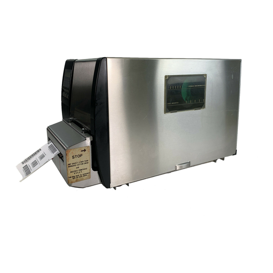
3. OVERVIEW 3. OVERVIEW 3.1 Front/Rear View Front View Message Display (LCD) Operation Panel Media Outlet 3.2 Operation Panel Fig. 3-2 Top Cover Memory Card Slot Supply Window Serial Interface Connector (RS-232C) Parallel I/F Connector (Centronics) Fig. 3-1 MESSAGE DISPLAY (LCD) Displays messages in the language selected by DIP switch. -
Page 14: Dip Switch Functions
2. The DIP switch #1-6 functions in accordance with equipment to be used. 3. If you would like to switch to READY/BUSY (DTR) or to READY/BUSY (RTS) of data protocol, please contact your authorized TOSHIBA TEC representative. Function (XOFF is output at the power off time.) (XOFF is output at the power off time.) -
Page 15: Installing The Printer
5. INSTALLING THE PRINTER 5. INSTALLING THE PRINTER Connecting the Power Cord and Cables Turn the POWER SWITCH to OFF before connecting the power cord or cables. Serial I/F Cable (RS-232C) Expansion I/O Cable Parallel I/F Cable (Centronics) WARNING! High Speed PC Inter- Power Cord face Cable (Option) EM1-33035... -
Page 16: Loading The Media
6. LOADING THE MEDIA 6. LOADING THE MEDIA 1. Do not touch moving parts. To reduce the risk that fingers, jewelry, clothing, etc., be drawn into the moving parts, push the switch in the “OFF” position to stop movement. 2. To avoid injury, be careful not to catch or jam your fingers while opening or closing the cover. The printer prints both labels and tags. - Page 17 NOTE: When using the label rolled with labels facing outside, please remove the upper plates of both paper holders using the following procedure. Failure to do this may cause a paper jam error. If you have any questions, please contact your nearest TOSHIBA TEC service representative. Groove Ridge...
- Page 18 6. LOADING THE MEDIA Removing the paper holders' upper plates from the media guide 1 Remove the two T-4x8 screws to detach the media guide from the printer. 2 Remove the SM-3x6 screw or the SM-3x8 screw to detach the paper holders' upper plates from the media guide.
- Page 19 6. LOADING THE MEDIA An easy way to set the black mark sensor position 1 Pull the media about 500 mm out of the front of the printer, turn the media back on it's self and feed it under the print head past the sensor so that the black mark can be seen from above. 2 Adjust the sensor position to that of the black mark (the upper hole indicates the position of the black mark sensor).
- Page 20 6. LOADING THE MEDIA 10. The media is now loaded and the sensor position is set. Batch type: NOTE: Set the selection switch to the STANDARD/STRIP position. Improper setting can affect the print quality. Strip type: 1 Remove enough labels from the leading edge media to leave 500 mm of backing paper exposed.
- Page 21 6. LOADING THE MEDIA Cutter type: Where a cutter is fitted load the media as standard and feed it through the cutter module. NOTES: 1. Be sure to cut the backing paper of label. Cutting labels will cause the glue to stick to the cutter, which may affect the cutter quality and shorten the cutter life.
-
Page 22: Loading The Ribbon
7. LOADING THE RIBBON 7. LOADING THE RIBBON 1. Do not touch moving parts. To reduce the risk that fingers, jewelry, clothing, etc., be drawn into the moving parts, push the switch in the “OFF” position to stop movement. 2. To avoid injury, be careful not to catch or jam your fingers while opening or closing the cover. There are two types of media available for printing on, these are standard media and direct thermal media (a chemically treated surface). -
Page 23: Inserting The Optional Flash Memory Card
8. INSERTING THE OPTIONAL FLASH MEMORY CARD 8. INSERTING THE OPTIONAL FLASH MEMORY CARD Turn the power OFF when inserting or removing the flash memory card. CAUTION: To protect memory cards, discharge static electricity from your body by touching the printer rear cover prior touching the memory cards. - Page 24 9. CARE/HANDLING OF THE MEDIA AND RIBBON 9. CARE/HANDLING OF THE MEDIA AND RIBBON CAUTION: Be sure to read carefully and understand the Supply Manual. Use only media and ribbon which meet specified requirements. Use of non-specified media and ribbon may shorten the head life and result in problems with bar code readability or print quality.
-
Page 25: General Maintenance
10. GENERAL MAINTENANCE 10. GENERAL MAINTENANCE 1. Be careful when handling the print head as it becomes very hot. 2. Care must be taken not to injure yourself with the printer paper cutter. 3. Do not touch moving parts. To reduce the risk that fingers, jewelry, clothing, etc., be drawn into the moving parts, push the switch in the “OFF”... -
Page 26: Covers And Panels
10. GENERAL MAINTENANCE 10.2 Covers and Panels The covers should be cleaned by wiping with a dry cloth or a cloth slightly dampened with a mild detergent solution. NOTE: Clean the printer cover with an electrostatic free cleaner for automated office equipment. 1. - Page 27 10. GENERAL MAINTENANCE Cleaning the Cutter Unit 1. Be sure to turn the power off before cleaning the cutter unit. 2. The cutters are sharp and care should be taken not to injure yourself when cleaning. 1. Loosen two screws and remove the cutter cover. 2.
-
Page 28: Threshold Setting
10. GENERAL MAINTENANCE 10.4 Threshold Setting For the printer to maintain a constant print position it uses the transmissive sensor to detect the gap between labels by measuring the amount of light passing through the media. When the media is pre- printed, the darker (or more dense) inks can interfere with this process causing paper jammed errors. -
Page 29: Auto Ribbon Saving Mode
10. GENERAL MAINTENANCE Threshold setting procedure (For firmware version 2.5 or earlier) 1 Turn the power on. 2 Load the pre-printed label. (Any position) 3 Press the [PAUSE] key once. 4 Hold down the [PAUSE] key for more than 3 seconds and it will begin to feed. After it has fed the 2 label, release the [PAUSE] key. -
Page 30: Troubleshooting
11. TROUBLESHOOTING 11. TROUBLESHOOTING If you cannot solve a problem with the following solutions, do not attempt to repair it yourself. Turn the power off, unplug the printer, then contact your Authorized Service representative for assis- tance. Error Message PAPER JAM 1. - Page 31 11. TROUBLESHOOTING Error Message EXCESS HEAD The print head is too hot. TEMP HEAD ERROR This message is displayed when sending the head broken check command ([ESC] HD001 [LF] [NUL]) and the print head has a broken element. RIBBON ERROR There is a fault with the ribbon sensor.
- Page 32 11. TROUBLESHOOTING Error Message example) When an error is detected in a com- PC001; 0A00, mand 20 bytes of the command are displayed. (ESC, LF, NUL are not displayed.) Command error 0300, 2, 2 Other Error Hardware or software trouble. Message NOTE: If an error is not cleared by pressing the [RESTART] key, the power must be switched off then on again.
- Page 34 PRINTED IN JAPAN EM1-33035...
- Page 35 TEC Thermal Printer B-570 SERIES Product Description Document No. EM10-33006A Original Nov., 1993 (Revised Feb., 2000) Table of Contents PRINTED IN JAPAN...
- Page 36 3.5 FANFOLD PAPER GUIDE MODULE: B-4905-FF-QM ... 3- 3 CAUTION: 1. This manual may not be copied in whole or in part without prior written permission of TOSHIBA TEC. 2. The contents of this manual may be changed without notification.
-
Page 37: Outline Of The System
1. OUTLINE OF THE SYSTEM 1. OUTLINE OF THE SYSTEM 1.1 FEATURES OF THE B-570 SERIES 1) Various bar codes, characters and graphic data can be printed using both thermal transfer and thermal direct methods. This printer can also print writable characters and logos at designated coordinates by using a graphic command. -
Page 38: Overview And Dimensions (Approximate)
1. OUTLINE OF THE SYSTEM 1.3 OVERVIEW AND DIMENSIONS (APPROXIMATE) 1.3.1 Front View/Rear View Front View Message Display (LCD) Operation Panel Media Outlet 1.3.2 Operation Panel ON LINE POWER ERROR FEED RESTART PAUSE Fig. 1-3 1.3.3 Dimensions (Approximate) Standard With cutter module : 291 mm (W) x 521 mm (D) x 308 mm (H) Top Cover Memory Card Slot Serial Interface... -
Page 39: Basic Specifications
1. OUTLINE OF THE SYSTEM 1.4 BASIC SPECIFICATIONS 1) Printing method ... Thermal direct printing or thermal transfer printing For the thermal transfer printing it may occur that horizontal lines printed within 20 mm from the print start position of the first label become lighter than other. Please adjust the print tone according to what you print. - Page 40 1. OUTLINE OF THE SYSTEM NW-7/CODE39/ITF/MSI/Industrial 2 of 5 ... The width of narrow bars, wide bars and spaces Data Matrix ... The width of one cell can be changed in a range of 9) Type of characters 1 Times Roman medium (8, 10 point) 2 Times Roman bold (10, 12, 14 point) 3 Times Roman Italic (12 point) 4 Helvetica medium (6, 10, 12 point)
-
Page 41: Electronics Specifications
1. OUTLINE OF THE SYSTEM 3 Auto cut mechanism When the cutter module is installed, the backing paper and tag paper are cut individually (stop and cut). Minimum cut length is 25.4 mm (tag paper) or 38 mm (label). Cutter 18) Power supply QQ model: AC 100 ~ 120 V + 10%, -15%, 50/60Hz QP model: AC 220 ~ 240 V + 10%, -15%, 50Hz... - Page 42 1. OUTLINE OF THE SYSTEM (5) Error detection Parity check: Framing error: This error occurs when no stop bit is found in the frame specified starting Overrun error: This error occurs when subsequent data is input before the data input to (6) Data entry code: (7) Receiving buffer: (8) Protocol...
- Page 43 1. OUTLINE OF THE SYSTEM READY/BUSY (RTS) Protocol • When initialized after power on, this printer becomes ready to receive data and converts the RTS signal to "High" level (READY). • The printer converts the RTS signal to “Low” level (BUSY) when the blank positions in the receive buffer amount to 800 Bytes or less.
- Page 44 1. OUTLINE OF THE SYSTEM Pin description Pin No. FG (Framed Ground) RD (Received Data) TD (Transmit Data) CTS (Clear to Send RTS (Request to Send) DTR (Data Terminal Ready) SG (Signal Ground) DSR (Data Set Ready) (10) Interface circuit Input circuit Signal level Input voltage...
- Page 45 SN74LS14 or equivalent SN74LS14 or equivalent 100P SN7406 or equivalent Printer COM1 Photo-coupler TPL521 (TOSHIBA) 1.5 ELECTORONICS SPECIFICATIONS Logical level (input) "1" = 2~5 V "0" = 0~0.4 V Logical level (input) "1" = 2.4~5 V "0" = 0~0.4 V 100P Fig.
- Page 46 1. OUTLINE OF THE SYSTEM Output circuit There are six output circuits, and each output is an open collector. The voltage of Vcc is 24 V (max.) while the operating current is 150 mA. For other details, please refer to the Expansion I/O specification. Sensor/switch 1 Head up switch (micro switch) This switch, attached at the lower left of the print head as viewed from the media outlet, detects...
- Page 47 1. OUTLINE OF THE SYSTEM Feed gap sensor (Transmissive sensor) This sensor detects the difference in potential between the backing paper and the label to find the print position of the label. The feed gap sensor is located 8 mm to the right of the black mark sensor.
- Page 48 1. OUTLINE OF THE SYSTEM Rewind full sensor (Transmissive sensor) This sensor detects excessive winding when winding backing paper or label onto the take- up spool. It is positioned 195.3 mm (Tr side) and 150.9 mm (LED side) from the platen, and the detection point is 92.5 mm from the main frame.
-
Page 49: Supply Specifications
Detail specifications and other information on the media and ribbon are described in Supply Manual by model. It is issued by and sent from TOSHIBA TEC H.Q. (Sales Division) upon release of new model or manual's revision. When purchasing the supplies locally, be sure to refer to the Supply Manual for details, or trouble may occur. - Page 50 2. SUPPLY SPECIFICATIONS 2) Tag Paper Black Mark Min. 12 mm 50.8 ~ 140.0 mm Fig. 2-3 NOTE: The reflection rate of the black mark is 10% or less at wavelength of 950 nm. A square hole can substitute for the black mark. When the square hole is used, no printing is allowed on the back side.
- Page 51 Winding method Ribbon Core Shape 68 ~ 134 mm NOTE: When purchasing ribbons locally, they must meet the above size. There may be TOSHIBA TEC-approved ribbons which do not fall within the above size, however, they have to functional problem.
-
Page 52: Care And Handling Of The Media And Ribbon
2. SUPPLY SPECIFICATIONS Leader tape Adhesive tape Fig. 2-9 Connection between leader tape and ribbon 2.3 CARE AND HANDLING OF THE MEDIA AND RIBBON CAUTION: Be sure to read carefully and understand the Supply Manual. Use only media and ribbon which meet specified requirements. -
Page 53: Cutter Module
"stop and cut" mode. B-4205-QM To purchase the cutter module, please contact your distributor or TOSHIBA TEC H.Q. can assist in finding one for you. This interface board quickly controls command transfer and printing. - Page 54 3. OPTIONAL KIT 3.2 HIGH SPEED PC INTERFACE BOARD: B-4800-PC-QM Command transfer and printing can be processed quickly by connecting a PC and the printer via a FIFO (first-in first-out) IC on the high speed PC interface board. For details, refer to the specification for high speed PC interface.
-
Page 55: Memory Module
3. OPTIONAL KIT 3.3 MEMORY MODULE This memory module is a D-RAM PC board used to extend the image buffer. An image buffer, equipped with 2MB (2MB x 1) as standard, can be expanded up to 4MB by installing the 2MB of D-RAM PC board. Part No. - Page 58 PRINTED IN JAPAN EM10-33006A...
- Page 59 TEC Thermal Printer B-570 SERIES Maintenance Manual Document No. EM18-33010A Original Nov., 1993 (Revision Feb., 2000) Table of Contents PRINTED IN JAPAN...
- Page 60 3. Please refer to your local Authorized Service representative with regard to any queries you may have in this manual. TABLE OF CONTENTS EM18-33010A (Revision Date: Feb. 10, 2000) Page Copyright © 2000 by TOSHIBA TEC CORPORATION All Rights Reserved 570 Ohito, Ohito-cho, Tagata-gun, Shizuoka-ken, JAPAN...
-
Page 61: Unpacking
1. UNPACKING 1. UNPACKING 1.1 PROCEDURE 1) Open the carton. 2) Unpack the accessories from the carton. 3) Unpack the side pad (L)/(R) and the printer from the carton. 4) Place the printer on a level surface. Owner’s Manual Side Pad (L) Power Cord Head Cleaner Supply... -
Page 62: Major Unit Replacement
2. MAJOR UNIT REPLACEMENT 2. MAJOR UNIT REPLACEMENT Disconnect power cord before replacing important parts. CAUTION: 1. NEVER separate the ribbon motors from the attaching plate (bracket), because doing so will change their adjustment. (See Fig. 2-8) 2. NEVER remove the two screws painted red on the side of the print block. (See Fig. 2-13) 3. -
Page 63: Replacing The Ps Unit, I/F Pc Board And Cpu Pc Board
2. MAJOR UNIT REPLACEMENT 2.1 REPLACING THE PS UNIT, I/F PC BOARD AND CPU PC BOARD CAUTION: Replace only with same type and ratings of fuse for continued protection against risk of fire. 1) Remove the three FL-4x6 screws and disconnect the two connectors to detach the PS unit. 2) Remove the FL-3x5 screw and the four locking supports to remove the I/F PC board. - Page 64 2. MAJOR UNIT REPLACEMENT 6) Adjust the ribbon end sensor. Use the following Ribbons; TTM-78 (Maker: Fujicopian) 1 Set the ribbon so that the ribbon end sensor can detect the ribbon. Turn the power on. 2 Turn the VR1 so that the voltage between Pin 1 (GND) and Pin 7 of CN12 is 3.0 0.2 V with an oscilloscope.
-
Page 65: Replacing The Stepping Motor
2. MAJOR UNIT REPLACEMENT 2.2 REPLACING THE STEPPING MOTOR 1) Remove the two black screws to detach the front plate, remove the two FL-4x6 screws to detach the belt cover. Front Plate Black Screw 2) Unclamp and disconnect the connector from CN13 on the CPU PC board. 3) Remove the two SM-4x8B screws, loosen the two belts from the pinion gear, and remove the stepping motor. -
Page 66: Replacing The Ribbon Motors
2. MAJOR UNIT REPLACEMENT 2.3 REPLACING THE RIBBON MOTORS CAUTION: NEVER separate the ribbon motors from the attaching plate because doing so will change their adjustment. 1) Disconnect the connector and remove the two SM-3x5B screws to detach the ribbon motors. Attaching Plate Ribbon Motor Screw (SM-3x5B) -
Page 67: Replacing The Solenoid
2. MAJOR UNIT REPLACEMENT 2.5 REPLACING THE SOLENOID NOTE: The following procedure can be employed without removing the top cover and left side cover. 1) Before removing the ribbon stopper, check its attaching direction for later installation. Remove the ribbon stopper from the ribbon shaft on which the ribbon is wound. 2) Remove the two SM-4x8B screws, disconnect the connector CN1 on the RSV PC board to detach the solenoid unit. - Page 68 2. MAJOR UNIT REPLACEMENT NOTE: Make sure to remove any dust that appears during removal or installation because it may affect the print quality. 4) Replace the solenoid and attach it to the solenoid attaching plate. 5) Assemble the solenoid unit so that the head up link engages the spring pin. Head Up Link CAUTION: Take care to orient the screws so that they are vertically aligned with the solenoid attaching plate.
-
Page 69: Replacing The Print Head
2. MAJOR UNIT REPLACEMENT 2.6 REPLACING THE PRINT HEAD CAUTION: 1. NEVER touch the element when handling the print head. 2. NEVER touch the connector pins to avoid a breakdown of the print head by static electricity. 3. NEVER remove the two screws painted red on the side of the print block. 4. - Page 70 2. MAJOR UNIT REPLACEMENT Adjusting the print head position 1 Fit the jig in the platen and strip shaft. 2 Press the jig at an angle of 45 until it is sung against the print head. Then secure the print head. Strip Shaft 3 Remove the jig.
- Page 71 2. MAJOR UNIT REPLACEMENT 2.6.2 New type print head NOTE: NEVER loosen screws other than two SM-4x8B. 1) Turn the head lever clockwise to lower the print head. Remove the two SM-4x8B screws. 2) Turn the head lever counterclockwise and disconnect the two connectors to detach the print head from the print block.
-
Page 72: Replacing The Platen And Feed Roller
2. MAJOR UNIT REPLACEMENT (1) Loosen the screws c securing the print head position adjusting pin. (2) Loosen the screws b one by one, slightly move the print head backward or forward, and then tighten the screws b and c . Ensure that the print head is parallel to the platen. If not, print tone will be uneven. - Page 73 2. MAJOR UNIT REPLACEMENT 3) Disconnect the connector for the strip sensor (LED). 4) Remove the six screws (FL-4x6, B-4x12 and P-3x12) to detach the right plate ass’y. Connector Strip Sensor (LED) NOTE: The machine with a serial number of 4T x x x x x x or later is not equipped with the red screws because of the change in the right plate shape.
-
Page 74: Replacing The Paper Sensor
2. MAJOR UNIT REPLACEMENT 2.8 REPLACING THE PAPER SENSOR NOTE: Turn the knob until the paper sensor reaches full forward. 1) Disconnent the connector for the strip sensor (LED) to remove right plate ass’y. (See Figs. 2-17 and 2-18.) 2) Disconnect the connectors for the paper sensor. 3) Remove M1.5 E-ring, M3 washer and paper sensor unit. -
Page 75: Replacing The Pinch Roller Shaft Ass'y
2. MAJOR UNIT REPLACEMENT 2.10 REPLACING THE PINCH ROLLER SHAFT ASS’Y 1) Turn the head lever to position 3 , and release the ribbon shaft holder plate. 2) Remove the black screw to detach the media guide plate. 1.5 mm~2.5 mm Printer Block Base Media Guide Plate Black Screw... - Page 76 2. MAJOR UNIT REPLACEMENT Adjustment 1. Install the pinch roller unit so it parallels the base. If it does not, change the engaging position of the pinch roller belt and the pulley. 2. Attach the jig to the platen, feed roller and pinch roller shaft as shown in the figure below. Then attach the pinch roller cover to the pinch roller frame with the three B-4x12 screws.
-
Page 77: Correcting Skew Printing
2. MAJOR UNIT REPLACEMENT 3. Turn the head lever clockwise to lock the pinch roller shaft ass’y. Attach the spring plate to the pinch roller frame with the two SM-4x8B screws, pushing the spring plate toward the rear of the printer. Pinch Roller Shaft Ass’y NOTE: Check that the pinch roller shaft ass’y moves up and down smoothly when turning the head lever clockwise and counterclockwise. -
Page 78: Installation Procedure For The Optional Equipment
3. INSTALLATION PROCEDURE FOR THE OPTIONAL EQUIPMENT 3. INSTALLATION PROCEDURE FOR THE OPTIONAL EQUIPMENT Make sure to unplug the power cord before installing the optional equipment. 3.1 HIGH SPEED PC INTERFACE BOARD (B-4800-PC-QM) The high speed PC interface board can be used together with the IBM PC-AT or its compatible machine only. - Page 79 3. INSTALLATION PROCEDURE FOR THE OPTIONAL EQUIPMENT 6. Connect the printer cable to the connector (CN1) on the BPE PC board. 7. Put the cable strain relief of the printer cable in the notch of the cable support plate. Secure the cable strain relief to the cable support plate by turning the nut.
-
Page 80: Cutter Module (B-4205-Qm)
Cutter Cover Take-up/Cutter Harness NOTE: For the B-570 series, the take-up/cutter harness enclosed with the B-4205-QM is not used but the take-up harness connected to CN2 on the PWM PC board. 1. Remove the top cover and left side cover. (See Fig. 2-1.) 2. - Page 81 3. INSTALLATION PROCEDURE FOR THE OPTIONAL EQUIPMENT 7. Install the cutter unit with the attached screws (cutter attaching screw, FL-4x6). When installing the cutter, make sure that the cutter guide is not in contact with the platen. If it is, print failure or noise may be caused.
- Page 82 3. INSTALLATION PROCEDURE FOR THE OPTIONAL EQUIPMENT 10. Mount the cutter cover with the two screws. Screw 11. Reassemble the motor cover, rewind full sensor (Tr), I/F PC board, left side cover and top cover in order. 12. After reassembly is complete, perform a test print to confirm that the cutter works properly. After printing a print sample at a speed of 8”/sec., feed the media about 33 mm and check that the swing cutter works without error.
-
Page 83: Memory Module
3. INSTALLATION PROCEDURE FOR THE OPTIONAL EQUIPMENT 3.3 MEMORY MODULE 3.3.1 For Old CPU Board 1. Remove the top cover and left side cover. (See Fig. 2-1.) 2. Hold the memory module so that the Pin 1 is on the upper right, then attach the memory module to the IC socket. - Page 84 3. INSTALLATION PROCEDURE FOR THE OPTIONAL EQUIPMENT 3.3.2 For New CPU PC Board 1. Open the right side cover and the top cover. (Refer to Fig. 2-1.) 2. Remove the left side cover. (Refer to Fig. 2-1.) 3. Directly connect the D-RAM PC board to CN16 on the CPU PC board, and then secure it with the two locking support.
-
Page 85: Fanfold Paper Guide Module (B-4905-Ff-Qm)
3. INSTALLATION PROCEDURE FOR THE OPTIONAL EQUIPMENT 3.4 FANFOLD PAPER GUIDE MODULE (B-4905-FF-QM) Description Fanfold Paper Guide(rear) Fanfood Paper Guide (front) 1. Open the top cover. 2. Remove the T-4x8 screws to detach the paper guide ass’y at the center of the printer and attach the fanfold paper guide (front) with these same screws. -
Page 86: Mechanism Description
4. MECHANISM DESCRIPTION 4. MECHANISM DESCRIPTION 4.1 CUTTER DRIVE (CUTTER MODE) The printer supplies DC + 27 V to the cutter motor to rotate the cutter motor and clutch counter clockwise. The arm swings like a pendulum and moves the fixed slide cutter up and down to make a cut. Fixed Cutter Slide Cutter After making a cut, the arm turns the micro switch off and the cutter home position is detected. -
Page 87: Harness Wiring
4. MECHANISM DESCRIPTION 4.2 HARNESS WIRING TH Sensor Rewind Full Sensor Strip Sensor DC Motor Harness Clamp LCD Harness I/F PC Board Ass’y LED Harness HP Harness Inlet Ass’y Cutter Harness Sensor Take-up Harness Solenoid Harness Harness Clamp Cable Band (Do not bind the strip sensor, stepping motor and Solenoid Harness) HS Harness... -
Page 88: Troubleshooting
• Replace the LED board/LCD. • Replace the LCD/LED harness. • Replace the CPU PC board. • Use the media approved by TOSHIBA TEC. • Clean the print head. • Fasten the head lever completely. • Re-adjust the print head. - Page 89 Cause • Replace the print head. • Replace the print head harness. • Replace the CPU PC board. • Use only TOSHIBA TEC specified media. • Clean the print head and remove the dust from the media. • Use only TOSHIBA TEC specified ribbon.
- Page 90 CAUTION: 1. This manual may not be copied in whole or in part without prior written permission of TOSHIBA TEC. 2. The contents of this manual may be changed without notification. 3. Please refer to your local Authorized Service representative with regard to any queries you may have in this manual.
-
Page 91: Diag. Test Operation
6. DIAG. TEST OPERATION 6. DIAG. TEST OPERATION 6.1 OUTLINE OF THE DIAG. TEST OPERATION In system mode the diag. test operation is used to diagnose the printer and to set the parameters by using the [FEED], [RESTART] and [PAUSE] keys on the operation panel. (Type I) is started from the power off state and the parameter setting (Type II) is started while the printer is on-line or printing. - Page 92 6. DIAG. TEST OPERATION n Type 2 The parameter setting such as feed length fine adjustment or cut/strip position fine adjustment can be changed while the printer is on-line or printing. Pressing the [PAUSE] key causes the printer to enter parameter setting mode. Reset mode is provided for this procedure to cancel the steps which follow the [PAUSE] key without turning the power off.
-
Page 93: Self Test Mode
6. DIAG. TEST OPERATION 6.2 SELF TEST MODE In self test mode the printer status is printed in two types of sample print. The result of the head broken element check is indicated in the display. 6.2.1 Maintenance Counter Printing The data from 1 to 31 on a sample print is printed. - Page 94 6. DIAG. TEST OPERATION Sample Print [Print Condition] Preset count Print speed : 127 mm/sec. Sensor : No sensor Printing method : Thermal transfer Supply length : 50 mm Issuing mode : Batch printing 1) Maintenance Counter Item Total media distance covered Media distance Print distance...
- Page 95 6. DIAG. TEST OPERATION 2) Parameters (11) Character code selection Font zero selection (12) Control code selection (13) Ribbon type selection (14) Feed length fine adjustment (19) (PC), (KEY) (15) Cut/strip position fine adjustment (20) (PC), (KEY) (16) Back feed length fine adjustment (21) (PC), (KEY) (17)
-
Page 96: Automatic Diagnostic Printing
6. DIAG. TEST OPERATION 6.2.2 Automatic Diagnostic Printing The data from 1 to 9 on a sample print is printed. Turn on the power while holding down the [FEED] key and [PAUSE] key. < 1 > D I A G N O S T I C Press the [PAUSE] key. - Page 97 6. DIAG. TEST OPERATION Sample Print [Print Condition] Preset count Print speed : 127 mm/sec. Sensor : No sensor Printing method : Thermal transfer Supply length : 50 mm Issuing mode : Batch printing 1 PROGRAM/MASK ROM Check PROGRAM V1.0 NOTES: 1.
- Page 98 6. DIAG. TEST OPERATION 3 EEPROM Check EEPROM 4 DRAM Check DRAM 1024KB NOTE: If an error is detected during DRAM check, the display od readable/writable area will stop when the error occurs. 5 Flash Memory Card Check CARD Read/write check OK: Data in the check area can be properly read/written.
- Page 99 6. DIAG. TEST OPERATION 6 Sensor 1 Check SENSOR1 0 0 0 0 0 0 0 0 , 1 0 1 1 0 0 1 1 Fixed to 1 Cutter home position switch status Home position Other position Rewind full sensor status Normal Excess Slit sensor #1 (ribbon rewind) status...
- Page 100 6. DIAG. TEST OPERATION Print status content description of each sensor/switch Sensor/Switch Head up switch Cutter home position switch Rewind full sensor Slit sensor #1 (ribbon rewind) Slit sensor #2 (ribbon feed) Strip sensor Ribbon end sensor 7 SENSOR2 Check SENSOR2 [H] 3.1V [R] 3.3V...
- Page 101 6. DIAG. TEST OPERATION 8 DIP SW Check 8 7 6 5 4 3 2 1 DIP SW 0 0 0 0 0 0 0 0 NOTE: The DIP switch 1-7 is to be set to 0 (OFF:OPEN) regardless of setting item. 9 EXP.
-
Page 102: Head Broken Element Check
6. DIAG. TEST OPERATION 6.2.3 Head Broken Element Check The printer automatically performs the head broken element check. The result of the head broken element check is indicated in the display. < 1 M A L E N D NOTES: 1. If the head broken element check results in ‘HEAD ERROR’, the print head must be replaced after referring to Section 2.6 Replacing the Print Head. -
Page 103: Parameter Setting Mode
6. DIAG. TEST OPERATION 6.3 PARAMETER SETTING MODE The following items are set in the parameter setting mode. The values set in this mode are printed on the sample print of the maintenance counter. Setting procedure and functions are provided below. Turn on the power while holding down the [FEED] key and [PAUSE] key. - Page 104 6. DIAG. TEST OPERATION Parameter Setting Mode Table Mode Name FEED ADJUST CUT ADJUST BACK FEED ADJ. X ADJUST TONE ADJUST <T> (Thermal transfer printing) TONE ADJUST <D> (Thermal direct printing) FONT CODE ZERO FONT CODE RIBBON RIBBON ADJ <FWD> (Ribbon feed motor) RIBBON ADJ <BAK>...
-
Page 105: Feed Length Fine Adjustment
6. DIAG. TEST OPERATION 6.3.1 Feed Length Fine Adjustment Turn on the power while holding down the [FEED] key and [PAUSE] key. < 1 > D I A G N O S T I C Press the [FEED] key. < 2 >... - Page 106 6. DIAG. TEST OPERATION 6.3.2 Cut/Strip Position Fine Adjustment Turn on the power while holding down the [FEED] key and [PAUSE] key. < 1 > D I A G N O S T I C Press the [FEED] key. < 2 >...
- Page 107 6. DIAG. TEST OPERATION 6.3.3 Back Feed Length Fine Adjustment Turn on the power while hoding down the [FEED] key and [PAUSE] key. < 1 > D I A G N O S T I C Press the [FEED] key. <...
- Page 108 6. DIAG. TEST OPERATION Feed Length Fine Adjustment Example + 0.0 mm Feed Direction - 10.0 mm + 10.0 mm Cut Position Fine Adjustment Example + 0.0 mm Feed Direction - 12.0 mm + 12.0 mm - 10 mm + 10 mm Cut Position Black Mark + 12 mm...
- Page 109 6. DIAG. TEST OPERATION When using a label with a length of less than 38 mm : Case 1 Condition: Issue command [ESC]XS, feed command [ESC]T and eject command [ESC]IB are received. Label pitch: 38.0 mm or less, with cut, feed gap sensor, cut position fine adjustment value 10 mm or less, and issue mode set to C (cut).
- Page 110 6. DIAG. TEST OPERATION Strip Position Fine Adjustment Example + 0.0 mm + 3.0 mm + 3.0 mm - 3.0 mm - 3.0 mm NOTE: The print stop position when printing the label in strip mode varies according to label length as the strip mode printing stops so that the edge of the strip shaft is 4 mm from the middle of the gap.
- Page 111 6. DIAG. TEST OPERATION Back Feed Length Fine Adjustment Example + 0.0 mm Feed Direction +3.0 mm -3.0 mm -3.0 mm Print start position +3.0 mm 6-21 EM18-33010A 6.3 PARAMETER SETTING MODE Fig. 6-15 Fig. 6-16 Fig. 6-17...
-
Page 112: X Axis Fine Adjustment
6. DIAG. TEST OPERATION 6.3.4 X Axis Fine Adjustment Turn on the power while holding down the [FEED] key and [PAUSE] key. < 1 > D I A G N O S T I C Press the [FEED] key. < 2 >... - Page 113 6. DIAG. TEST OPERATION X Axis Fine Adjustment Example Top first printing + 0.0 mm -50.0 mm -50.0 mm + 50.0 mm +50.0 mm NOTES: 1. The X axis fine adjustment is performed to fine adjust the X axis of the drawing in the left or right direction.
-
Page 114: Print Tone Fine Adjustment
6. DIAG. TEST OPERATION 6.3.5 Print Tone Fine Adjustment Power off Turn on the power while holding down the [FEED] key and [PAUSE] key. < 1 > D I A G N O S T I C Press the [FEED] key. <... - Page 115 6. DIAG. TEST OPERATION 6.3.6 Character Code Selection Turn on the power while holding down the [FEED] key and [PAUSE] key. < 1 > D I A G N O S T I C Press the [FEED] key. < 2 >...
- Page 116 6. DIAG. TEST OPERATION 6.3.7 Font Zero Selection Turn on the power while holding down the [FEED] key and [PAUSE] key. < 1 > D I A G N O S T I C Press the [FEED] key. < 2 >...
- Page 117 6. DIAG. TEST OPERATION 6.3.8 Control Code Selection Turn on the power while holding down the [FEED] key and [PAUSE] key. < 1 > D I A G N O S T I C Press the [FEED] key. < 2 >...
- Page 118 6. DIAG. TEST OPERATION Press the [PAUSE] key. T L O L C O D E 1 Press the [PAUSE] key. T R O L C O D E 2 Press the [PAUSE] key. T R O L C O D E 3 Go to B on the previous page.
- Page 119 6. DIAG. TEST OPERATION 6.3.9 Ribbon Type Selection Turn on the power while holding down the [FEED] key and [PAUSE] key. < 1 > D I A G N O S T I C Press the [FEED] key. < 2 >...
-
Page 120: Ribbon Motor Drive Voltage Fine Adjustment
6. DIAG. TEST OPERATION 6.3.10 Ribbon Motor Drive Voltage Fine Adjustment Turn on the power while holding down the [FEED] key and [PAUSE] key. < 1 > D I A G N O S T I C Press the [FEED] key. <... -
Page 121: Strip Wait Status Setting
6. DIAG. TEST OPERATION 6.3.11 Strip Wait Status Setting Turn on the power while holding down the [FEED] key and [PAUSE] key. < 1 > D I A G N O S T I C Press the [FEED] key. < 2 >... -
Page 122: Stacker Selection
6. DIAG. TEST OPERATION 6.3.12 Stacker Selection Turn on the power while holding down the [FEED] key and [PAUSE] key. < 1 > D I A G N O S T I C Press the [PAUSE] key. < 2 > P A R A M E T E R Press the [PAUSE] key fourteen times. - Page 123 6. DIAG. TEST OPERATION 6.3.13 Threshold Manual Fine Adjustment for the Black Mark Sensor Turn on the power while holding down the [FEED] key and [PAUSE] key. < 1 > D I A G N O S T I C Press the [PAUSE] key.
- Page 124 6. DIAG. TEST OPERATION 6.3.14 Threshold Manual Fine Adjustment for the Feed Gap Sensor Turn on the power while holding down the [FEED] key and [PAUSE] key. < 1 > D I A G N O S T I C Press the [PAUSE] key.
- Page 125 6. DIAG. TEST OPERATION EM18-33010A (Revision Date: Jan. 14 ‘99) 6.3 PARAMETER SETTING MODE How To Calculate Theshold Fine Adjustment Value If the following cases occurred, threshold value for the paper sensors should be fine adjusted after referring to the next page. Case 1: When using tag paper, the black mark and the print area are distinguished from each other by the 1.5V or more difference of sensor output voltage.
- Page 126 6. DIAG. TEST OPERATION NOTE: The following operation cannot be performed unless the sensor type is changed by the issue command or feed command. (1) Using the sensor adjustment in Diag. mode, measure the sensor voltage at the following four points. Label: Print area Backing paper Tag paper: Print area Black mark...
-
Page 127: Kanji Code Selection
6. DIAG. TEST OPERATION 6.3.15 Kanji Code Selection Power off Turn on the power while holding down the [FEED] key and [PAUSE] key. < 1 > D I A G N O S T I C Press the [PAUSE] key. <... -
Page 128: Euro Font Code Selection
6. DIAG. TEST OPERATION 6.3.16 Euro Font Code Selection Turn on the power while holding down the [FEED] key and [PAUSE] key. < 1 > D I A G N O S T I C Press the [PAUSE] key. < 2 >... -
Page 129: Transmission Control Mode Selection
6. DIAG. TEST OPERATION 6.3.17 Transmission Control Mode Selection Turn on the power while holding down the [FEED] key and [PAUSE] key. < 1 > D I A G N < 2 > P A R A M Press the [PAUSE] key 19 times. / R T S Select the Transmission Control Mode with the [FEED] key... - Page 130 6. DIAG. TEST OPERATION 6.3.18 Reset Selection when the INPUT • PRIME Signal is ON. Reset ON/OFF when the INPUT • PRIME signal ON is selected. Turn on the power while holding down the [FEED] key and [PAUSE] key. < 1 >...
-
Page 131: Test Print Mode
6. DIAG. TEST OPERATION 6.4 TEST PRINT MODE Test print mode contains normal test print and process test print. 6.4.1 Normal Test Print Five kinds of test prints are provided in the test print mode. When performing the test print, 7 parameters should be set. - Page 132 6. DIAG. TEST OPERATION From B of the preceding page. Set the print count from those at the right by pressing the [FEED] key or [RESTART] key. (See NOTE 2.) Press the [PAUSE] key. (See NOTE 3.) Set the print speed Select the print speed from those at the right by pressing the [FEED] key or [RESTART] key.
- Page 133 6. DIAG. TEST OPERATION From B of the preceding page. Set the issue mode type Select the issue mode type from those at the right by pressing the [FEED] key or [RESTART] key. (See NOTE 2.) Press [PAUSE] key. (See NOTE 3.) Set the label length Select the label length from those at the right by pressing...
- Page 134 6. DIAG. TEST OPERATION From B of the preceding page. < 3 > T E S T Press the [PAUSE] key. From A of the preceding page. Select the test print from those at the right by pressing the [FEED] key or [RESTART] key.
- Page 135 6. DIAG. TEST OPERATION 9. When the transmissive ribbon is selected and DIP SW. 1-1 is set to ON, and the space area is also 20 mm or more, the printer automatically enters ribbon saving print mode. 10. When “AUTO PRINT” is selected, 5 pcs. of the 3-dot slant line labels, bar code labels and character labels are printed respectively after one label is fed.
- Page 136 6. DIAG. TEST OPERATION 6.4.2 Process Test Print In the process test print, the test print is automatically performed on the following conditions. Parameter setting and print tone fine adjustment value is ignored. OPERATION ISSUE COUNT : 5 labels each PRINT SPEED : 8 inches/sec.
- Page 137 6. DIAG. TEST OPERATION [Characters are printed on 5 labels.] < 3 > T E S T From A of the preceding page. [Bar code are printed on 5 labels. ] [Characters are printed on 5 labels.] < 3 > T E S T From B of the next page.
-
Page 138: Sensor Setting Mode
6. DIAG. TEST OPERATION 6.5 SENSOR SETTING MODE Thermistor check and black mark/feed gap sensor settings are provided in the sensor setting mode. The value set in this mode is printed as data of sensor 2 in Automatic diagnosis printing in self test mode. 6.5.1 Thermistor Check Thermistor check should be performed to check the environmental temperature and print head... -
Page 139: Black Mark Sensor Adjustment
6. DIAG. TEST OPERATION 6.5.2 Black Mark Sensor Adjustment Black mark sensor setting should be performed after replacing the CPU PC board or changing the tag paper to other maker’s one, or when a paper feed error occurs. < 1 >... - Page 140 6. DIAG. TEST OPERATION 6.5.3 Feed Gap Sensor Adjustment Feed gap sensor setting should be performed after replacing the CPU PC board or changing the label to other maker’s one, or when a paper feed error occurs. < 1 < 4 Press the [FEED] key and [RESTART] key at the same time.
- Page 141 6. DIAG. TEST OPERATION 6.5.4 Paper End Setting for Black Mark Sensor Paper end setting should be performed after replacing the CPU PC board or changing the tag paper to other maker’s one, or when a paper feed error occurs. <...
- Page 142 6. DIAG. TEST OPERATION 6.5.5 Paper End Setting for Feed Gap Sensor Paper end setting should be performed after replacing the CPU PC board or changing the label to other maker’s one, or when a paper feed error occurs. < 1 >...
-
Page 143: Ram Clear Mode
6. DIAG. TEST OPERATION 6.6 RAM CLEAR MODE In RAM clear mode, various data written on the EEP-ROM can be initialized. There are two clear functions; Maintenance counter clear and parameter clear in the parameter setting mode. After referring to the following table specify and clear or initialize the data. RAM Clear Mode Table Mode Name NO RAM CLEAR... - Page 144 6. DIAG. TEST OPERATION Mode Name PARAMETER CLEAR NOTES: 1. Total media distance covered (TL FEED) and the adjustment value for the sensors cannot be cleared. 2. Data stored on the flash memory card cannot be cleared with this procedure. To clear dada on the flash memory card, send the format command to ini tialize the card.
-
Page 145: Maintenance Counter Clear
6. DIAG. TEST OPERATION 6.6.1 Maintenance Counter Clear Press the [PAUSE] key. Press the [FEED] key and [RESTART] key at the same time. NOTE: Confirm that “COMPLETE” is displayed, then turn the power off. Power off Turn on the power while holding down the [FEED] key and [PAUSE] key. -
Page 146: Parameter Clear
6. DIAG. TEST OPERATION 6.6.2 Parameter Clear Press the [PAUSE] key. Press the [FEED] key and [RESTART] key at the same time. NOTE: Confirm that “COMPLETE” is displayed, then turn the power off. Power off Turn on the power while holding down the [FEED] key and [PAUSE] key. -
Page 147: Program Down Load
7. PROGRAM DOWN LOAD 7. PROGRAM DOWN LOAD 7.1 DOS VERSION The main program for the printer has been written onto the flash ROM. If the main program is upgraded, due to the addition/change of the specification, down load the main program from the PC to the printer with the down-load floppy disk and RS-232C interface or high speed PC interface. - Page 148 7. PROGRAM DOWN LOAD 7.1.3 DOWN LOAD PROCEDURE (1) Turn the PC power on. (2) Turn the printer power on. (3) Insert the program down load floppy disk into the PC. (4 Change the drive to A. Type A (5) Start the batch file “PDL”. Type Or copy the contents of the floppy disk in to the hard disk and start the program in the hard disk.
- Page 149 7. PROGRAM DOWN LOAD (11) When an error occurs, the following message is displayed together with the error code in line The following error occurred during transmission. (ERROR=##) Doing so will revert to the displayed described in step (6). Refer to the error code to find the cause of the error.
-
Page 150: Windows Version
Example SETUP DISK (1/3) Download Program for B-X (English) 12th December 1999 FMRM0057401 V001.000 Copyrigth 1999 TOSHIBA TEC CORPORATION All Rights Reserved Example B-572-QQ/QP INSTALL KIT V3.3 15th October 1999 FMRM0034812: D700 V012.000 EM18-33010A (Revision Date: Feb. 10, 2000) 7.2 WINDOWS VERSION... - Page 151 7. PROGRAM DOWN LOAD 7.2.2 Setup and System requirements Connect the B-570 printer to the PC via the RS-232C cable. (1) System Windows 95 or Windows 98 (Windows 3.1 is not supported.) (2) Interface Serial Interface only (3) Memory 16M byte minimum (32M byte or more recommended) (4) Hard Disk 5M byte minimum (10M byte or more recommended) (5) Wiring of RS-232C Interface Cable...
- Page 152 7. PROGRAM DOWN LOAD 7.2.3 Installation Procedure of Down Load Program (1) Start up Windows 95 or Windows 98, and then insert the Program Loader Setup Disk (1/3) into the PC floppy drive. (2) Click on the Start button then highlight Run and click on Run. (3) When the Run display appears, type in A:\SETUP.EXE and click on OK button.
- Page 153 (3) Click on the Start button to access the program menu. (4) Highlight “Programs” then highlight “TOSHIBA TEC” and click on Download Program for B- (5) The screen will change to display the initial screen of the Download Program for B-X.
- Page 154 (7) The file open screen will appear. Select the drive and the folder in which the binary file is stored. If you copy the binary file into the C:\Program Files\Toshiba TEC\BXDwnPrg folder which appears as the default, you will reduce the time for the program download.
- Page 155 7. PROGRAM DOWN LOAD (9) The display restores to the Download Program for B-X. Make sure of the Download file. (10) Select the Tool (T) drop down menu and then select Condition (C). (11) The communication setting window will appear. Choose COM1 or COM2 and then click on OK button.
- Page 156 7. PROGRAM DOWN LOAD (13) When the program has been successfully downloaded, the following message will appear. If an error occurs during downloading, make sure of the connection of the RS-232C cable, the DIP SW setting, the condition of the communication, and then retry the program download. NOTE: If you terminate the program download, select the File (F) drop down menu and then select Exit (X).
- Page 158 PRINTED IN JAPAN EM18-33010A...