Table of Contents
Advertisement
Quick Links
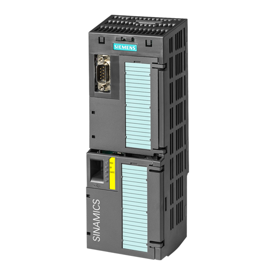
CU250S-2 Control Units
SINAMICS
SINAMICS G120
CU250S-2 Control Units
Compact Operating Instructions
05/2014
A5E32899990B AB
Fundamental safety
___________________
instructions
___________________
Scope of delivery
___________________
Installing
___________________
Commissioning
___________________
More information
Scan the QR code for
additional informati-
on on SINAMICS
G120.
1
2
3
4
5
Advertisement
Table of Contents

Related Manuals for Siemens SINAMICS G120 CU250S-2 Series


Summary of Contents for Siemens SINAMICS G120 CU250S-2 Series
- Page 1 Fundamental safety ___________________ CU250S-2 Control Units instructions ___________________ Scope of delivery ___________________ Installing SINAMICS ___________________ Commissioning SINAMICS G120 ___________________ CU250S-2 Control Units More information Compact Operating Instructions Scan the QR code for additional informati- on on SINAMICS G120. 05/2014 A5E32899990B AB...
- Page 2 Note the following: WARNING Siemens products may only be used for the applications described in the catalog and in the relevant technical documentation. If products and components from other manufacturers are used, these must be recommended or approved by Siemens. Proper transport, storage, installation, assembly, commissioning, operation and maintenance are required to ensure that the products operate safely and without any problems.
-
Page 3: Table Of Contents
Table of contents Fundamental safety instructions ......................4 General safety instructions ......................4 Industrial security ........................... 5 Scope of delivery ............................ 6 Installing ..............................7 Snapping the Control Unit onto the Power Module................ 7 Overview of the interfaces ......................8 Terminal blocks .......................... -
Page 4: Fundamental Safety Instructions
Fundamental safety instructions General safety instructions WARNING Risk of death if the safety instructions and remaining risks are not carefully observed If the safety instructions and residual risks are not observed in the associated hardware documentation, accidents involving severe injuries or death can occur. •... -
Page 5: Industrial Security
Siemens recommends strongly that you regularly check for product updates. For the secure operation of Siemens products and solutions, it is necessary to take suitable preventive action (e.g. cell protection concept) and integrate each component into a holistic, state-of-the-art industrial security concept. -
Page 6: Scope Of Delivery
● A CU250S-2 Control Unit ready for operation with installed firmware. Options for upgrading and downgrading the firmware can be found on the Internet: Firmware (http://support.automation.siemens.com/WW/news/en/67364620). The fieldbus interface of the Control Unit depends on the order number. The order number, the designation and the version of the hardware (e.g. 02) ①... -
Page 7: Installing
Installing Snapping the Control Unit onto the Power Module Installing the Control Unit on an IP20 Power Module Procedure Proceed as follows to connect Power Modules and Control Units: 1. Locate the lugs at the rear of the Control Unit in the matching recesses of the Power Module. -
Page 8: Overview Of The Interfaces
Installing 3.2 Overview of the interfaces Overview of the interfaces To access the interfaces at the front of the Control Unit, you must unplug the Operator Panel (if one is being used) and open the front doors. ① Terminal strips ②... - Page 9 SMC10, SMC20, SMC30, SME20 or SME25 The permissible combinations of encoders for speed control and position control are listed in the "Basic Positioner" Function Manual, see also: Manuals for the Control Unit (http://support.automation.siemens.com/WW/view/en/30563628/133300). CU250S-2 Control Units Compact Operating Instructions, 05/2014, A5E32899990B AB...
-
Page 10: Terminal Blocks
Installing 3.3 Terminal blocks Terminal blocks Terminal strips behind the upper front door Different reference potentials: The terminals labelled "GND" are connected internally. "GND" and "GND IN" are not connected internally. Figure 3-1 Interconnection example of the digital inputs with external 24 V power supply Interconnecting the analog inputs (terminals 3, 4 and 10, 11) For the analog inputs, you may use the internal 10 V supply (example: terminals 1 …... - Page 11 Installing 3.3 Terminal blocks Optional 24 V supply (terminals 31, 32) Connection of the optional 24 V supply has the following advantages: ● The Control Unit remains in operation after disconnection of the Power Module from the line supply. The Control Unit thus maintains the fieldbus communication, for example. ●...
- Page 12 Installing 3.3 Terminal blocks Factory setting of the terminal strips The factory setting of the terminals depends on the Control Unit. Control Units with USS or CANopen interface The fieldbus interface is not active. Figure 3-3 Factory setting of the CU250S-2 and CU250S-2 CAN Control Units CU250S-2 Control Units Compact Operating Instructions, 05/2014, A5E32899990B AB...
- Page 13 Installing 3.3 Terminal blocks Control Units with PROFIBUS or PROFINET interface The function of the fieldbus interface depends on DI 3. Figure 3-4 Factory setting of the CU250S-2 DP and CU250S-2 PN Control Units CU250S-2 Control Units Compact Operating Instructions, 05/2014, A5E32899990B AB...
-
Page 14: Operator Panels
● p0015 = 7 (setting in STARTER: "Fieldbus with data set switchover") Further default settings can be found in the Operating Instructions, see also: Manuals for the Control Unit (http://support.automation.siemens.com/WW/view/en/30563628/133300). Wiring the terminal strip in compliance with EMC 1. If you use shielded cables, then you must connect the shield to the mounting plate of the control cabinet or with the shield support of the inverter through a good electrical connection and a large surface area. -
Page 15: Commissioning
265) Help for the operation and for the functions of the commissioning tools: ● STARTER videos (http://www.automation.siemens.com/mcms/mc-drives/en/low-voltage- inverter/sinamics-g120/videos/Pages/videos.aspx) ● Startdrive tutorial (http://support.automation.siemens.com/WW/view/en/73598459) Commissioning with STARTER is described in the following. Commissioning with STARTER Creating a STARTER project Procedure In order to create a new project, proceed as follows: 1. - Page 16 Commissioning 4.1 Commissioning with STARTER Transferring inverters connected via USB to the project Procedure Proceed as follows to transfer an inverter connected via USB to your project: 1. Switch on the inverter power supply. 2. First insert a USB cable into your PC and then into the inverter. 3.
- Page 17 Commissioning 4.1 Commissioning with STARTER Setting the USB interface Procedure Proceed as follows to set the USB interface in STARTER: 1. In this case set the "Access point" to "DEVICE (STARTER, Scout)" and the "PG/PC interface" to "S7USB". 2. Press the "Update" button. You have set the USB interface.
- Page 18 Commissioning 4.1 Commissioning with STARTER Performing the configuration Follow the steps of the configuration wizard and enter the data of your application. Loading the configured data into the drive Procedure Proceed as follows to load the configured data into the drive: 1.
- Page 19 Commissioning 4.1 Commissioning with STARTER DANGER Risk of injury or material damage as a result of machine movements when switching on the motor Switching on the motor for identification purposes may result in hazardous machine movements. Secure dangerous machine parts before starting motor data identification: •...
-
Page 20: Connecting The Inverter To The Fieldbus
Where can I find instructions for the fieldbus connection of the inverter? You can find instructions for the fieldbus connection on the Internet: ● Application examples (http://support.automation.siemens.com/WW/view/en/60733299) ● Operating Instructions, "Inverter with CU250S-2 Control Units": Manuals for the Control Unit (http://support.automation.siemens.com/WW/view/en/30563628/133300) ●... - Page 21 Commissioning 4.2 Connecting the inverter to the fieldbus Meaning Explanation 0 = Stop RFG The output of the ramp-function generator stops at the actual value. 1 = Enable RFG The output of the ramp-function generator follows the setpoint. 0 = Inhibit setpoint The inverter brakes the motor with the ramp-down time p1121 of the ramp-function generator.
-
Page 22: Frequently Required Parameters
Description (GSD) for (http://support.automati inverter writes its GSD or GSDML to the memory PROFIBUS on.siemens.com/WW/vi card once you insert this card in the inverter and ew/en/23450835) set p0804 to 12. You can then transfer the file to your programming device or PC using the... - Page 23 Commissioning 4.3 Frequently required parameters Parameter Explanation r0722 Digital inputs status Terminal 5 DI 0 Selection of the possible settings: p0840 ON/OFF (OFF1) Terminal 6, 64 DI 1 p0844 No coast-down (OFF2) Terminal 7 DI 2 p0848 No quick stop (OFF3) Terminal 8, 65 DI 3 p0855 Unconditionally release holding brake...
- Page 24 Commissioning 4.3 Frequently required parameters Parameter Explanation p0756 Analog input type 0: Unipolar voltage input (0 V …+10 V) 1: Unipolar voltage input monitored (+2 V... +10 V) Terminals 3, 4 AI 0 2: Unipolar current input (0 mA …+20 mA) Terminals 10, 11 AI 1 3: Unipolar current input monitored (+4 mA …+20 mA)
-
Page 25: More Information
Manuals for the Control German, Unit Operating Instructions Installing, commissioning and Italian, (http://support.automation. for the SINAMICS G120 inverter operating the inverter. French, siemens.com/WW/view/en/ with the CU250S-2 Control Setting the inverter functions. Spanish, 30563628/133300) Units Technical data. Chinese Function Manual, Basic Commissioning the basic... -
Page 26: Product Support
Italy Spain Great Britain +33 (0) 821 801 122 +49 (0)911 895 7222 +39 (02) 24362000 +34 902 237 238 +44 161 446 5545 Other service telephone numbers: Product support (http://www.siemens.com/automation/service&support) CU250S-2 Control Units Compact Operating Instructions, 05/2014, A5E32899990B AB...