
Related Manuals for Philips LTC 5108/50


Summary of Contents for Philips LTC 5108/50
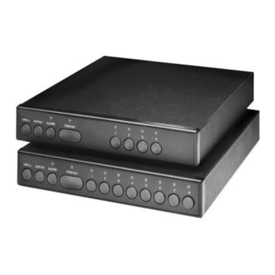
- Page 1 Philips Communication & Security Systems 4- and 8-Position Premium Sequential Switchers LTC 5104 Series LTC 5108 Series...
- Page 2 IMPORTANT SAFEGUARDS 1. Read Instructions - All the safety and operating instructions should be read before the unit is operated. 2. Retain Instructions - The safety and operating instructions should be retained for future reference. 3. Heed Warnings - All warnings on the unit and in the operating instructions should be adhered to.
-
Page 3: Safety Precautions
SAFETY PRECAUTIONS CAUTION RISK OF ELECTRIC SHOCK. DO NOT OPEN! CAUTION: TO REDUCE THE RISK OF ELECTRICAL SHOCK, OPEN COVERS. SERVICEABLE PARTS INSIDE. REFER SERVICING TO QUALIFIED SERVICE PERSONNEL. This label may appear on the bottom of the unit due to space limitations. The lightning flash with an arrowhead symbol, within an equilateral triangle, is intended to alert the user to the presence of uninsulated "dangerous voltage"... - Page 4 SICHERHEITSVORKEHRUNGEN VORSICHT RISIKO EINES ELEKTRISCHEN SCHLAGES NICHT ÖFFNEN! VORSICHT: UM EINEN ELEKTRISCHEN SCHLAG ZU VERMEIDEN, ABDECKUNG NICHT WARTUNGEN ALLER PERSONAL ÜBERLASSEN. Aus Platzgründen kann diese Warnung auf der Unterseite des Gerätes angebracht sein. Das Blitzsymbol im gleichseitigen Dreieck soll den Benutzer auf nicht isolierte “Hochspannung”...
-
Page 5: Table Of Contents
One (1) cable assembly with 15-pin connector. If an item appears to have been damaged in shipment, replace it properly in its carton and notify the shipper. If any items are missing, notify your Philips Communication & Security Systems Inc. Sales Representative or Customer Service. -
Page 6: Video Inputs And Looping Outputs
Video Inputs and Looping Outputs For each of the 4 or 8 channels there are two BNC connectors on the rear panel. One of these connectors is to be used as a video input while the other connector may be used as a looping output. -
Page 7: Resetting To Default Programming
Resetting to Default Programming To restore factory default program settings, press and hold SKIP/clr and then press ALARM key for 1 second (see Screen 3). Screen 3 To abort and resume normal operation, press the DWELL key. To reset the unit to factory defaults, press the SKIP/clr key to move the cursor to the "RESET"... -
Page 8: Alarm Capture
4.11 Alarm Capture This menu item appears only if the Auto Alarm Reset Mode is selected (see Screen 5). When the Alarm Capture is ON, Screen 5 alarm call-ups are held for at least the length of its Alarm Capture Time. After its Alarm Capture Time has expired, the alarm call-up remains as long as its contact closure exists. -
Page 9: Status Line
4.15 Status Line This menu determines what will be displayed on the on- screen Status Line. There are three options: 1. A full status line which contains the camera number, camera title, sequence mode, and alarm status information, 2. Camera number and title only, or 3. -
Page 10: Operation
OPERATION DWELL Key The DWELL key is used to enter the Dwell Time configuration menu and to enter other menus. A momentary push will enter the Dwell Time menu. Holding DWELL for over 1 second will enter the program mode. SKIP/clr Key The SKIP/clr key has two uses. -
Page 11: Illustrations
ILLUSTRATIONS LTC 5104 Series Connector Diagram Front Panel and Back Panel 6 11 2 7 12 8 13 4 9 14 5 10 15 S9405013AE NC: No Connection NO: Normally Open Function Ground Alarm 3 Monitor Strobe 1 Data 0 Alarm 1 Alarm 4 Alarm Relay (NO) -
Page 12: Ltc 5108 Series
LTC 5108 Series Connector Diagram Front Panel and Back Panel 6 11 2 7 12 8 13 4 9 14 5 10 15 S9405013AE NO: Normally Open Function Ground Alarm 3 Alarm 6 Monitor Strobe 1 Data 0 Alarm 1 Alarm 4 Alarm 7 Alarm Relay (NO) - Page 13 Typical Installation Using LTC 5108 Series Switcher...
- Page 14 Typical Installation Using LTC 5108 Series Switcher and a LTC 5135 Series Controller/Follower...
-
Page 15: Wiring Table Of Cable From Switcher To Controller/Follower
Wiring Table of Cable From Switcher to Controller/Follower Note: Cable provided with unit From: Alarm/Accessory Cable Connector of LTC 5104 Series or LTC 5108 Series (Cable supplied) Function Ground Monitor Strobe Data 0 Alarm Relay (NO) Data 1 Alarm Relay (NO) Data 2 All Monitor Strobes from the TC8135 Series must be connected together. -
Page 16: Font Tables
è í î ñ û ’ ¿ Æ > < • ß Printed in U.S.A. © 1998 by Philips Communication & Security Systems Inc. All Rights Reserved. > — Å Ü å ü µ é ë ê ò ó õ...