Siemens SIMATIC C7-621 Manual
As-i control system, first steps with step 7-mini and protool/lite
Hide thumbs
Also See for SIMATIC C7-621:
- Hardware installation manual (138 pages) ,
- Manual (48 pages) ,
- Manual (20 pages)

Related Manuals for Siemens SIMATIC C7-621


Summary of Contents for Siemens SIMATIC C7-621
- Page 1 SIMATIC SIMATIC C7-621 AS-i Control System First steps with STEP 7-Mini and ProTool/Lite Guide Edition 07/1999 Getting Started with C7-621-AS-i...
-
Page 3: Table Of Contents
Operating the C7-621-AS-i ........................53 Program Example..........................54 Microsoft and Microsoft MS are registered trademarks, and Windows is a mark of Microsoft Corporation in the United States and other countries. SIMATIC is registered trademarks of SIEMENS AG. Getting Started with C7-621-AS-i... - Page 4 Introduction 04/99 SIEMENS COROS OP3 SIMATIC S7-300 SHIFT ENTER MPI interface Programming device connection and communication (global data) AS-Interface master Can control up to 31 slaves Up to 248 binary elements External I/O extension Interface for connecting an expansion unit...
-
Page 5: Introduction
04/99 Introduction Introduction The SIMATIC C7-621-AS-i control system gives you a variety of options for clearly structured, convenient automation, operation and monitoring of your process. The integrated AS-Interface allows high-powered automation solutions at the process level. This brochure shows you how easily and quickly you can solve your tasks with the C7-621-AS-i, the... -
Page 6: Hardware Configuration
SIMATIC documentation on CD-ROM (in 5 6ES7 398-8AE00-8YE0 languages) PC/MPI adapter 6ES7 972-0CA22-0XA0 RS232 cable 6ES7 901-1BF00 0XA0 SIMATIC C7-621-AS-i control system 6ES7 621-6BD00-0AE3 +24V power supply PS307 6ES7 307-1BA00-0AA0 AS-Interface power pack and AS-i cable 3RX9307-0AA00 2 x connecting cable with M-12 socket and... -
Page 7: Checklist For Startup
04/99 Introduction Checklist for startup The following basic steps are necessary for starting up the SIMATIC C7-621-AS-i: Þ Install STEP 7 or STEP 7-Mini on PC/programming device Þ Install ProTool or ProTool/Lite integrated under STEP 7 or STEP 7-Mini on PC/programming device Þ... -
Page 8: Sample Project: Sorting System
AS-i functions step by step. You will set up an AS-i network, program a PLC program and learn how to establish the link with the integrated C7 operator panel. SIMATIC C7-621 DC5V... -
Page 9: Setup And Configuration Of The As-I Network
C7 addressing function, it is therefore necessary to connect all new slaves to the AS-i cable consecutively to ensure that they are each assigned a unique address. Slave 1 Slave 5 Slave 3 SIMATIC C7-621 DC5V FRCE STOP AS-I shaped... - Page 10 Setup and Configuration of the AS-i Network 04/99 The C7-CPU must be in STOP mode for you to be able to configure your AS-i network. S H IF T On the C7-621-AS-i control system, select the System Functions menu by pressing the keys.
- Page 11 04/99 Setup and Configuration of the AS-i Network Conf.Mode: Enabled Disable setconf You must switch from protected mode to configuring mode. To do this, press Wait a moment, then press . If the above mask appears, you may proceed. Otherwise, repeat the last two steps.
- Page 12 Setup and Configuration of the AS-i Network 04/99 to select the Status menu. In the menu that now appears, press Press again to see the status display of the existing and activated slaves. If you have set up your AS-i network as described, the screen will look like this. ----- ----- ----- ----- ----- ----- -- If the display is different from your configuration, please check your settings against the descriptions...
-
Page 13: Programming Preparations
04/99 Programming Preparations Programming Preparations Starting STEP 7 Once STEP 7 has been installed, the “SIMATIC Manager” icon appears on the Windows 95 desktop and the “SIMATIC” program group appears in the Start menu. As with all other Windows 95 appli- cations, you start the program by double-clicking on the SIMATIC Manager icon or by selecting the Start menu →... - Page 14 Programming Preparations 04/99 You also have to set the PC/programming device interface. To do this, select the menu item Options → Set PG/PC-Interface... Set the PC Adapter(MPI) in the dialog box that appears. If the PC Adapter is not displayed in the window, you can install it now. Activate the Install button and follow the instructions.
-
Page 15: Creating A Project
04/99 Programming Preparations For the local connection, select the COM port to which you connected the PC/MPI cable. Save the settings with OK . You can now start to create your project. Creating a project Select the menu item File → New . In the dialog box that appears, create a new project with the name GetStart. -
Page 16: Defining The Hardware
Programming Preparations 04/99 Defining the hardware Open the station system_1 by double-clicking on it. Select the Hardware folder and open it, again with a double click. In the Hardware Configuration window go to the Hardware Catalog via Insert → Hardware Compo- nents . -
Page 17: Setting Up A Bit Memory Address Area For Clock Memories
04/99 Programming Preparations Setting up a bit memory address area for clock memories Clock memories are bit memories which periodically modify their binary value (pulse-pause ratio: 1:1). You need these memories in the following programming example. To enable you to set up the clock memory, you must make the following settings. In the Hardware Configuration window open the dialog window Properties - C7-CPU621 by double- clicking on the C7-CPU-621 icon. -
Page 18: Setting The Address Areas And Accessing The As-I User Data
Programming Preparations 04/99 Setting the address areas and accessing the AS-i user data In standard operation, the AS-i communications processor behaves like an I/O module. It occupies 16 input and 16 output bytes in the analog area of the controller. Each slave on the AS-i cable is assigned four bits (a nibble) by the C7-AS-i-CP. - Page 19 04/99 Programming Preparations Select the Blocks folder in the SIMATIC Manager and insert a data block with Insert → S7 Block → 4 Data Block . In the dialog box that appears, assign the internal identifier DB1. Open data block DB1 and select Data Block as the desired type. Accept the settings with OK . Select the second entry in the Name column and enter here the name M1_In1.
- Page 20 Programming Preparations 04/99 Getting Started with C7-621-AS-i...
- Page 21 04/99 Programming Preparations Save your data block DB1 by clicking on the icon in the toolbar. In the application the following addresses in DB1 are significant: Adress Symbol Status format Meaning M1_IN1 Optical Bero M1_IN2 Inductive Bero M3_IN1 Position switch M5_IN2 ON button M5_IN3...
-
Page 22: Program Generation
Program Generation 04/99 Program Generation Once you have set up your AS-i network and preset all the necessary values in STEP 7, you can now program your control task. We will restrict this to configuring the eject process of the sorting system. DB1.DBX0.1 DB1.DBX1.0 DB1.DBX0.0... -
Page 23: Editing A Block
04/99 Program Generation Editing a block Now open the LAD/STL/FBD editor by double-clicking on the newly created Function FC1 in the SIMATIC MANAGER. Click on Title next to the block number FC1 and assign the block name Belt control. Now give the first network the name Initial position. To do this, click on the entry Title next to the network number. -
Page 24: Saving A Block
Program Generation 04/99 Network 2 : Belt ON DB1.DBX2.0 // Belt_ON button on casing M 15.0 // Initial position DB1.DBX4.0 // Conveyor belt ON Network 3 : Belt OFF DB1.DBX2.3 // Belt_OFF button on casing DB1.DBX4.0 // Output Belt_ON Network 4 : Operating mode display DB1.DBX4.0 // Belt ON DB1.DBX6.0... -
Page 25: Deleting The C7-Cpu Memory / Overall Reset Of C7-Op
04/99 Program Generation Select the operating mode STOP by pressing . The STOP LED lights up. If a password has not yet been entered, the system requests one. When the C7 is shipped, the password is preset to 100. Enter the digits 100 via the numeric keypad and confirm your input with ENTER. -
Page 26: Loading Blocks
Loading individual blocks In the SIMATIC Manager select the function FC1 and load this block into the CPU of the SIMATIC C7-621-AS-i by clicking once on the icon in the toolbar. Then load the organization block OB1 into the CPU in the same way. - Page 27 04/99 Program Generation In the SIMATIC Manager go to your offline project and insert another function in the Blocks folder. Give it the internal ID FC2, select STL again as the generation language, and open the block. Insert the following program lines in the individual networks: FC2 : Eject conditions Network 1 : Count DB1.DBX1.0...
- Page 28 Program Generation 04/99 Programming of the FC2 is now complete. The module can be saved and transferred to the CPU. Now you must also consider the possible faults in your belt control. In the SIMATIC Manager open the FC1. Insert the program line AN M16.0 in Network 1 . The complete network then looks like this: Network 1 : Initial position DB1.DBX0.0 // Opto_Bero: no parcel...
-
Page 29: Saving Ram To Rom
04/99 Program Generation Saving RAM to ROM Because the PLC program, when loaded into the C7-CPU, is only transferred into the unbuffered load memory and not automatically also into the C7-CPU flash memory, the program would be lost when the C7-621-AS-i was restarted. -
Page 30: Preparations For Op Configuration
Preparations for OP Configuration 04/99 Preparations for OP Configuration Starting ProTool, creating the configuration There are two ways to create an OP configuration. You can create a new (empty) configuration and configure all the necessary system functions (e.g. change of operating mode, assignment of passwords etc.) yourself, or you can use a standard configuration delivered with ProTool as the basis for your configuration. -
Page 31: Online Help
04/99 Preparations for OP Configuration To check and, if necessary, correct the PLC parameters, display the dialog box with the PLC para- meters from the Driver window by activating the Parameters button (see dialog box directly below). When you have entered all the settings, close the dialog box by activating the button OK . In the Projekt Wizard confirm this step with Weiter >. -
Page 32: Displaying And Entering Values In Screens
Displaying and Entering Values in Screens 04/99 Displaying and Entering Values in Screens You can start by configuring your first screen. Open the Screen Editor with the menu item Insert → Screen . This action calls up the Screen-PIC_6. screen entry, 1 line) screen entry, 2 line) -
Page 33: Transferring The Configured Data
04/99 Displaying and Entering Values in Screens Transferring the configured data Before the actual transfer, you must perform three steps: • Save • Generate the project • Define the transfer parameters (once only). To save the project, select File → Save in the menu bar. Then in the menu bar select File →... -
Page 34: Extending The Configuration
Displaying and Entering Values in Screens 04/99 Once the transfer is complete, the C7 starts up. Press the ENTER key. If the start screen appears on the C7, the transfer was successful. SIMATIC C7-621 System_1 DC5V STOP FRCE S H IF T ENTER If the transfer was not successful, repeat the steps beginning on page 33. - Page 35 04/99 Displaying and Entering Values in Screens Configuring the input field Use the cursor to select the first line of the first screen entry. Using the cursor control keys, position the cursor behind the text Filling time. Activate the menu item Insert → Input/Output Field or press the button in the function bar.
- Page 36 Displaying and Entering Values in Screens 04/99 Configuring the output field Position the cursor in the first line of the second screen entry after the configured text Curr.number:. In the menu bar, select Insert → Input/Output Field. In the Input / Output dialog box, set the field type to Output and the field length to 4. .
- Page 37 04/99 Displaying and Entering Values in Screens The editor automatically inserts a new line, in which you enter the next data block word. This data word 2 is to have the name number_parcels, the type WORD , and the initial value W#16#0. Create the data word 4 with the name messages, the type WORD and the initial value W#16#0.
-
Page 38: Linking And Branching Between Screens Via Softkeys
Displaying and Entering Values in Screens 04/99 The following diagram shows the connection between the value entered, the control program and the current number of parcels counted. DB46 SIMATIC C7-621 Control program :STL DC5V FRCE STOP Parcels DBW0 L DB46.DBW 0... - Page 39 04/99 Displaying and Entering Values in Screens Click the button <<Add . The dialog box Parameters - Select Screen appears. In this dialog box, select the name of the screen you want to call up: Parcel_1. Do not change the parameters Entry Number or Field Number .
- Page 40 Displaying and Entering Values in Screens 04/99 Labeling softkey assignment So that the C7 operator knows which softkey is occupied, you need to define a text for this softkey, which will be displayed in the relevant screen. Proceed as follows: Position the text cursor in the second line of the screen above the softkey you have assigned, by entering blanks.
- Page 41 04/99 Displaying and Entering Values in Screens Once the transfer is complete, the C7 starts up. When you press the ENTER key, the start screen is displayed. SIMATIC C7-621 System_1 DC5V STOP FRCE S H IF T ENTER Activate the softkey to reach the system screen.
-
Page 42: Incorporating Standard Screens Into The Configuration
Incorporating Standard Screens into the Configuration 04/99 Incorporating Standard Screens into the Configuration At the start of the configuration, you selected the standard screens as the basis for your configuration and saved the file under the new name System_1. You will need the standard screens if you want to use the standard functions of the C7-621-AS-i. These functions include changing the operating mode, editing the password, logging on and off with the password, etc. -
Page 43: Configuring Event Messages
04/99 Configuring Event Messages Configuring Event Messages In the previous steps you could test the functioning of your system. What you still need is information on the current operation of your system - the so-called event messages. For example, you want a message to be displayed on the OP when you switch the system on. - Page 44 Configuring Event Messages 04/99 In the status line (not shown in the figure), you will see the relevant address which connects the message to the PLC. In your example, for message no. 001 the address is System ON: DB 46 DBX 5.0. Generating the control program To allow the exchange of data between the C7-CPU and C7-OP you must still adjust your control pro- gram and reload it into the C7.
- Page 45 With this control program and the configuration that you loaded, you can initiate the messages on the SIMATIC C7 device. Control program DBX 4.7 ..4.0 DBX 5.7 ..5.0 L MW20 Assigned message number T DB46.DBW4 Bit area for messages SIMATIC C7-621 Area pointer Plant ON DC5V FRCE STOP S H IF T ENTER The above figure shows the connection between the PLC and the OP when a message appears.
- Page 46 Configuring Event Messages 04/99 SIMATIC C7-621 System ON DC5V STOP FRCE S H IF T ENTER This completes the configuration. Getting Started with C7-621-AS-i...
-
Page 47: Symbolic Addressing
04/99 Symbolic Addressing Symbolic Addressing When programming with STEP 7 you work with operands such as I/O signals, bit memories, counters, timers, data blocks and function blocks. So far you have addressed these operands in your program absolutely (e.g. on DB46). However, it is helpful to assign symbolic names for them (e.g. on DB_OP, Belt control). -
Page 48: Setting Symbolic Representation
Symbolic Addressing 04/99 Setting symbolic representation To also display the symbolic names in your program, you must set the appropriate type of representation. In the offline data management, open the function FC1. In the LAD/STL/FBD Editor which appears, select the menu item View → Display → Symbolic Representation . The absolute addresses are replaced by the symbolic names. - Page 49 04/99 Symbolic Addressing In the Hardware Configuration window, open the dialog window Properties C7 CPU621 by double- clicking on the symbol C7 CPU621 . Open the Properties - MPI Nodes window by clicking the button Properties ... , and select the Subnet: MPI(1) .
- Page 50 Symbolic Addressing 04/99 Now open your C7-621 ProTool configuration and select the folder Controllers. Open the Controller System_1 by double-clicking . Click the Parameters... button. Select MPI(1) under Connect OP to network. MPI(1) appears under Choose a communication peer/symbol list , a nd the network parameters are displayed on a gray background.
- Page 51 04/99 Symbolic Addressing Open the Parcels_1 screen, double-click the variable Parcels and click the Edit button in the Input/Output field dialog window . In the dialog window that now appears, the symbolic names are displayed under Symbol . Select the name DB_OP.max_parcels under DB_OP in the variable list. The absolute addresses are displayed on a gray background.
- Page 52 Symbolic Addressing 04/99 Now the event messages still have to be given their symbolic names. In ProTool, select the Area Pointers window via the menu item System . In the Area Pointers window click on the Edit... button. In the Event Messages window, select the symbolic name DB_OP.messages and confirm your entries with OK .
-
Page 53: Operating The C7-621-As-I
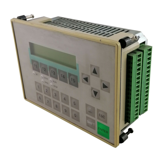
04/99 Operating the C7-621-AS-i Operating the C7-621-AS-i To help you operate the C7-621, the most important keys of the C7-621-AS-i are described briefly below. SIMATIC C7-621 Display Cursor keys DC5V Softkeys STOP FRCE ESCAPE key S H IF T ENTER key... -
Page 54: Program Example
Program Example 04/99 Program Example You have created the following STEP 7 program and put it into operation by following the instructions. DB1: Getting Started with C7-621-AS-i... - Page 55 04/99 Program Example Getting Started with C7-621-AS-i...
- Page 56 Program Example 04/99 DB46: OB 1: Network 1 : Route process image of AS-i line to DB Network 2 : Call system component belt control CALL FC 1 Network 3 : Call system component ejector Call FC 2 Network 4 : Write outputs FC1: Belt control Network 1 : Initial position DB1.DBX0.0...
- Page 57 04/99 Program Example Network 4 : Operating mode display DB1.DBX4.0 // Belt ON DB1.DBX6.0 // Green lamp on casing M 21.0 // Message flag FC2 : Eject conditions Network 1 : Count DB1.DBX1.0 // Position switch DB1.DBX4.0 // Belt ON DB1.DBX0.1 // Inductive Bero M30.0...
- Page 58 Program Example 04/99 Network 5 : Faults M21.1 // Fault_parcel sequence M21.2 // Fault_parcel stop M16.0 // Fault M16.0 // Fault M10.4 // Flashing frequency DB1.DBX6.1 // Red lamp on casing DB1.DBX2.1 // Acknowledgment button M21.1 // Fault_parcel sequence M21.2 // Fault_parcel stop Network 6 : Data interface MW20...