Table of Contents
Advertisement
Quick Links
Download this manual
See also:
Instruction Manual
Document Copyrights
Copyright 2006 by Kenwood Corporation. All rights reserved.
No part of this manual may be reproduced, translated, distributed, or transmitted in any
form or by any means, electronic, mechanical, photocopying, recording, or otherwise, for
any purpose without the prior written permission of Kenwood.
Disclaimer
While every precaution has been taken in the preparation of this manual, Kenwood
assumes no responsibility for errors or omissions. Neither is any liability assumed for
damages resulting from the use of the information contained herein. Kenwood reserves
the right to make changes to any products herein at any time for improvement purposes.
Advertisement
Table of Contents

Related Manuals for Kenwood TK-5400 Series


Summary of Contents for Kenwood TK-5400 Series
- Page 1 Kenwood. Disclaimer While every precaution has been taken in the preparation of this manual, Kenwood assumes no responsibility for errors or omissions. Neither is any liability assumed for damages resulting from the use of the information contained herein. Kenwood reserves...
- Page 2 800MHz APCO P25 TRANSCEIVER TK-5400 SERVICE MANUAL © 2002-6 PRINTED IN JAPAN B51-8632-00 ( N ) 595 TK-5400 (K) TK-5400 (K2) : With Keypad Antenna Antenna (KRA-24 : Option) (KRA-24 : Option) Knob assy Knob assy (Encoder) (Encoder) (K29-5282-14) (K29-5282-14) Knob assy Knob assy (Volume)
-
Page 3: Table Of Contents
KSC-20/24 (Rapid Charger) ........64 ment procedures contained within. SPECIFICATIONS ........... 65 NOTE WE CANNOT guarantee oscillator stability when using channel element manufactured by other than KENWOOD or its authorized agents. Unit X53-4030-XX X57-6530-10 Frequency range... -
Page 4: System Set-Up
TK-5400 SYSTEM SET-UP / OPERATING FEATURES Merchandise received License and frequency allocated by FCC TK-5400 K No keypad Model type Choose the type of transceiver TK-5400 K2 With keypad A personal computer (IBM PC or compatible), programming Transceiver programming interface (KPG-36), and programming software (KPG-78D) are required for programming. -
Page 5: Operating Features
TK-5400 OPERATING FEATURES !0 Orange key 2. Programmable Functions Press to activate its auxiliary function (page 4). Refer to the following tables to determine which func- !1 PTT (Push-To -Talk) switch tions are available for appropriate channels (N/A = Not Avail- Press this switch, then speak into the microphone to call able). - Page 6 TK-5400 OPERATING FEATURES / REALIGNMENT REALIGNMENT 3. Data Programming (PC Mode) 3-1. Preparation and Connection 1. Mode TK-5400 transceiver is programmed by using a personal computer, programming interface cable KPG-36, and pro- gramming software KPG-78D. User mode The programming software can be used with an IBM-PC or compatible machine.
-
Page 7: Realignment
TK-5400 REALIGNMENT • Make sure the communication speed between the FPRO 3. Firmware Programming Mode program and the transceiver settings are the same. Re- 3-1. Preface fer to section 3-4. for details. Flash memory is mounted on the transceiver. This al- •... -
Page 8: Disassembly For Repair
TK-5400 DISASSEMBLY FOR REPAIR Disassembly of Front Case and Chassis Remove the Side Key Assy 1. Remove the 2 screws ( ) and a cap fixed screw ( 1. The side key assy is clips form a slide-hook structure. Lift 2. -
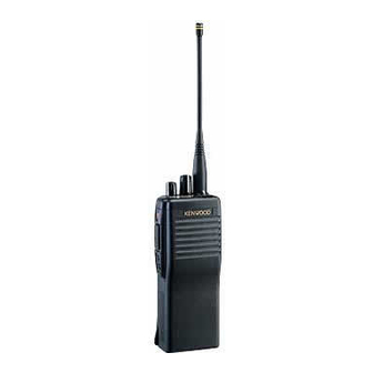
Page 9: Circuit Description
The VCO oscillation frequencies are 403 to 412.5MHz 1. Overview and 425.5 to 435MHz, and locking occurs at both ranges of The KENWOOD model TK-5400 is an 800MHz/FM/APCO doubled frequencies of 806 to 825MHz and 851 to 870MHz. hand-held transceiver designed to operate in the frequency The VCO output components, other than the doubled fre- range of 806 to 825MHz (TX)., 851 to 870MHz (TX/RX), the... - Page 10 TK-5400 CIRCUIT DESCRIPTION +B 7.5V 4. Power Supply Circuit The battery power (+B) is supplied from the battery ter- 3A FUSE minal to the TX-RX unit through a 3A fuse. The power (SB) 7.2V that passes through the power supply are routed to three AVR ICs (IC702, IC704, IC705), the DC/DC converter IC Q702 (C402) and the power transistor switch (Q5,Q6 : Control...
- Page 11 TK-5400 CIRCUIT DESCRIPTION 5-3. IF Amplifier 5-6. Audio Amplifier Circuit • TX-RX unit The 1st IF signal is amplified (Q304) and fed into IC303 in the MIX, IF AMP IC. The IF signal is then mixed with the The converted D/A signal from IC608 is amplified by AF 2nd local oscillator frequency of 44.395MHz to generate the amplifier IC606 (2/2).
- Page 12 TK-5400 CIRCUIT DESCRIPTION 6-2. Noise Cancelling Microphone Circuit 6. Transmitter System The two signals from INT MIC (Main & Sub) are fed to the 6-1. Microphone Amplifier positive (+) input (Sub) and to the negative (–) input (Main) of The signal from the noise canceller amplifier (control unit the IC3.
- Page 13 TK-5400 CIRCUIT DESCRIPTION 7-4. D/A Converter 7. Control Circuit IC605 is used as a conventional semi-fixed-resister con- The control unit has microprocessor IC507, flash verter. It controls the followings: memory IC508, and its peripheral circuits. It controls the TX- 1) Transmission power RX unit and transfers data to and from the control unit.
- Page 14 TK-5400 CIRCUIT DESCRIPTION / SEMICONDUCTOR DATA 7-7. DSP 1. PLL : SA7026DH (TX-RX Unit IC204) The DSP circuit consists of a DSP (IC611), a codec 1-1. Block Diagram (IC608), and an A/D converter (IC609) and processes the base band signal. The DSP (IC611) operates on an external Pump clock of 12.288MHz (the same as the CPU), the I/O section CLOCK...
-
Page 15: Semiconductor Data
TK-5400 SEMICONDUCTOR DATA 2. Microprocessor : 30620M8A-2W4GP (TX-RX Unit IC507) 2-1. Terminal Function Port Name Function Port Name Function P94/DA1/TB41N Not used : GND Pull-down HOLD Not used : Vcc Pull-up (HSDO) HSD Output (Not used) HLDA SB Contorol BCLK Not used : Vcc Pull-up EEPROM Clock Flash Memory RD bus... - Page 16 TK-5400 SEMICONDUCTOR DATA 3. DC/DC Converter : XC6365D103M (TX-RX Unit IC402) 3-1. Block Diagram 3-2. Pin Assignment Pin No. Pin Name Function EXT/ External transistor connection Phase compensation Power supply Error amp comparator Ground Buffer Chip enable – EXT/ – driver Output voltage set-up external Vref with...
-
Page 17: Components Description
TK-5400 COMPONENTS DESCRIPTION Control Unit (X53-4030-XX) -10 : K, -11 : K2 Ref. No. Part Name Description Ref. No. Part Name Description IC702 MOS IC Voltage Regulator Bi-polar IC AF Amplifier IC703 MOS IC Shift Register MOS IC Shift Register IC704,705 MOS IC Voltage Regulator... -
Page 18: Parts List
TK-5400 PARTS LIST New Parts. indicates safety critical components. L : Scandinavia K : USA P : Canada Parts without Parts No. are not supplied. Y : PX (Far East, Hawaii) T : England E : Europe Les articles non mentionnes dans le Parts No. ne sont pas fournis. Y : AAFES (Europe) X: Australia M: Other Areas... - Page 19 TK-5400 PARTS LIST CONTROL UNIT (X53-4030-XX) TX-RX UNIT (X57-6530-10) Desti- Desti- Ref. No. Address Parts No. Description Ref. No. Address Parts No. Description parts nation parts nation CK73FB1C474K CHIP C 0.47UF UDZ3.9(B) ZENER DIODE C33,34 CK73GB1H471K CHIP C 470PF IMN10 DIODE CK73GB1H102K CHIP C...
- Page 20 TK-5400 PARTS LIST TX-RX UNIT (X57-6530-10) Desti- Desti- Ref. No. Address Parts No. Description Ref. No. Address Parts No. Description parts nation parts nation C121 C92-0628-05 CHIP-TAN 10UF 10WV C338,339 CK73GB1E103K CHIP C 0.010UF C124 CC73GCH1H101J CHIP C 100PF C340 CC73GCH1H120J CHIP C 12PF...
- Page 21 TK-5400 PARTS LIST TX-RX UNIT (X57-6530-10) Desti- Desti- Ref. No. Address Parts No. Description Ref. No. Address Parts No. Description parts nation parts nation C634 CC73GCH1H121J CHIP C 120PF CF301,302 L72-0916-05 CERAMIC FILTER C635 CK73GB1H471K CHIP C 470PF L40-2763-69 SMALL FIXED INDUCTOR (2.7NH) C638 CK73GB1H102K CHIP C...
- Page 22 TK-5400 PARTS LIST TX-RX UNIT (X57-6530-10) Desti- Desti- Ref. No. Address Parts No. Description Ref. No. Address Parts No. Description parts nation parts nation RK73GB1J101J CHIP R 1/16W R236 RK73GB1J823J CHIP R 1/16W RK73HB1J682J CHIP R 6.8K 1/16W R237 RK73GB1J221J CHIP R 1/16W R8,9...
- Page 23 TK-5400 PARTS LIST TX-RX UNIT (X57-6530-10) Desti- Desti- Ref. No. Address Parts No. Description Ref. No. Address Parts No. Description parts nation parts nation R507 RK73GB1J104J CHIP R 100K 1/16W R644 RK73GB1J473J CHIP R 1/16W R509 RK73GB1J104J CHIP R 100K 1/16W R645 RK73GB1J471J...
- Page 24 TK-5400 PARTS LIST TX-RX UNIT (X57-6530-10) Desti- Desti- Ref. No. Address Parts No. Description Ref. No. Address Parts No. Description parts nation parts nation R735 RK73GB1J821J CHIP R 1/16W IC703 BU4094BCFV MOS IC R736 RK73GB1J473J CHIP R 1/16W IC704,705 XC6204B502MR MOS IC R737 RK73GB1J104J...
-
Page 25: Exploded View
TK-5400 EXPLODED VIEW 30x2 30x2 Control unit (A/6) (F/6) 37x2 Control unit TX-RX unit (B/6) (A/2) (B/2) 75 74 (D/6) : N14-0578-04 : N14-0594-04 C M2.6 x 8 BLK : N30-2608-45 D M2.6 x 5 (Bi) BLK : N35-2605-45 E M2 x 3 : N78-2030-46 F M2 x 3.5 : N79-2035-46... -
Page 26: Packing
TK-5400 PACKING 6 Dressing plate 7 Cap (SP/MIC) (B03-0594-04) (B09-0363-03) 13 Stopper 40 Cushion (Cap) (D32-0421-24) 705 Pamphlet (G13-1688-04) 55 Protection bag (H25-0029-04) 79 Screw set (N99-2004-05) 65 Belt hook (J29-0652-35) 10 Instruction manual (B62-1606-00) 54 Packing fixture (H12-3018-02) 56 Item carton case (H52-1880-02) 707 Sticker 706 UPC code label... -
Page 27: Adjustment
TK-5400 ADJUSTMENT Test Equipment Required for Alignment Test Equipment Major Specifications Maximum 900MHz or more. Standard Signal Generator Frequency Range (SSG) Modulation Frequency modulation and external modulation. Output –133dBm/0.05µV to 7dBm/501mV Power Meter Input Impedance 50Ω. Operation Frequency Up to 900MHz. Measurement Range Full scale of 10W or so. - Page 28 TK-5400 ADJUSTMENT • Panel tuning Repair Jig (Chassis) Use jig (part No.: A10-4064-03) for repairing the TK-5400 Place the TX-RX unit on the jig and fit it with 7 screws. Note : Supply power from an external power supply (Battery terminal : +, jig (chassis) : –) 2 : RED (RX AF OUTPUT) 3 : BLACK (RX AF OUTPUT)
- Page 29 TK-5400 ADJUSTMENT Straightening the Coaxial Cable Panel Test Mode 1. When you connect the coaxial connector to the PCB, the 1. This mode is used for making transceiver connection coaxial cable may be slightly curved toward the chassis tests and clearing the memory. (Fig.
- Page 30 TK-5400 ADJUSTMENT • Key Function • Test Signalling Controls Operation RX Signalling TX Signalling APCO/ Analog [Selector] Used to select a test channel. None None Analog [PTT] Used to switch between transmission and None 100Hz Square wave Analog reception. QT 67.0Hz QT 67.0Hz Analog [Top 1]...
- Page 31 TK-5400 ADJUSTMENT 3. Flow Chart Function Name Display Adj Remarks Frequency Tune TX Frequency Adj. [Side 2] [Orange] High Power adj. (Low edge) TX High Power TX High Power (Low) [Side 2] [Side 2] TX High Power (Cen) High Power adj. (Center) [Side 2] TX High Power (Hi) High Power adj.
- Page 32 TK-5400 ADJUSTMENT BER (Bit Error Rate) Measurement FMWD 1. The Panel Test Mode is used to measure the BER with FM WIDE Max Deviation Deviation adj. (Center) the TK-5400 (see 1. Panel Test.). [Side 2] 2. Select a filter to be measured (see Filter Mode.). FMWD FM WIDE Max Deviation TA Deviation TA adj.
- Page 33 TK-5400 ADJUSTMENT Transmitter Section Measurement Adjustment Item Condition Specifications/Remarks Test- Unit Terminal Unit Parts Method equipment ± 100Hz 1. Frequency 1) Set panel tuning mode. Power meter Panel Panel Top1/ 815.500MHz adjustment CH : 4 (Center) f. counter Top2 LCD display : TXF PTT : ON Press [Side 2] to store the digit number after adjustment.
- Page 34 TK-5400 ADJUSTMENT Measurement Adjustment Item Condition Specifications/Remarks Test- Unit Terminal Unit Parts Method equipment 7. MIC 1) Set panel tuning mode. Deviation Panel Panel Top 1/ Fixed digit number sensitivity CH : 4 (Center) meter Top 2 129. adjustment LCD display : MIC LO Oscilloscope PTT : ON Set at constant value 129.
- Page 35 TK-5400 ADJUSTMENT Measurement Adjustment Item Condition Specifications/Remarks Test- Unit Terminal Unit Parts Method equipment 13. APCO high 1) Set panel tuning mode. Deviation Panel Panel Top 1/ 2827Hz 2771~2883Hz deviation CH : 4 (Center) Top 2 adjustment LCD display : HDVA t LO (TA) Deviation meter filter setting LPF : 3kHz...
- Page 36 TK-5400 ADJUSTMENT Measurement Adjustment Item Condition Specifications/Remarks Test- Unit Terminal Unit Parts Method equipment ± 50Hz 19. FM narrow 1) Set panel tuning mode Deviation Panel Panel Top1/ 2.05kHz deviation CH : 4 (Center) meter Top2 adjustment LCD display : FMND t LO Oscilloscope (TA) PTT : ON...
- Page 37 TK-5400 ADJUSTMENT Measurement Adjustment Item Condition Specifications/Remarks Test- Unit Terminal Unit Parts Method equipment 26. TX low 1) Set panel test mode. Power meter Panel Check 0.7~1.3W power check CH : 1 Ammeter at low Signalling : 1 frequency Toggle SW : A side PTT : ON Press [Side 2] to store the digit number after adjustment.
- Page 38 TK-5400 ADJUSTMENT Measurement Adjustment Item Condition Specifications/Remarks Test- Unit Terminal Unit Parts Method equipment 33. FM 1) Set panel test mode Deviation Panel Check 3.3kHz± 50Hz NPSPAC Mode : NP meter deviation CH : 4 (Center) Oscilloscope check (TA) Signalling : 1 Toggle SW : B side Side Universal...
- Page 39 TK-5400 ADJUSTMENT Measurement Adjustment Item Condition Specifications/Remarks Test- Unit Terminal Unit Parts Method equipment 40. FM wide 1) Set panel test mode. Deviation Panel Adjust AG input 15mV± 5mV Mode : WD meter level to get a sensitivity CH : 1 Oscilloscope standard MOD., check...
- Page 40 TK-5400 ADJUSTMENT Receiver Section Measurement Adjustment Item Condition Specifications/Remarks Test- Unit Terminal Unit Parts Method equipment 1. SQ threshold 1) Set panel tuning mode. Panel Side Side 2 Writing 12dB SINAD – 4dB level writing CH 4 : (Center) Orange 3kHz DEV.
- Page 41 TK-5400 ADJUSTMENT Measurement Adjustment Item Condition Specifications/Remarks Test- Unit Terminal Unit Parts Method equipment 8. Battery 1) Set panel tuning mode. Power meter Panel Side Orange Writing 6.8V at BATT terminal warning CH : 4 (Center) level writing LCD display : BATT DC VTVM Bottom BATT Set DC power supply 6.8V at terminal...
-
Page 42: Terminal Function
TK-5400 TERMINAL FUNCTION CN No. Pin No. Name I/O Function CN No. Pin No. Name I/O Function – Audio GND. TX-RX UNIT (X57-6530-10) BTL input + for external speaker. CN701 EXT/INT speaker switch input. SP– BTL input – for external speaker. O BTL output + for external speaker. - Page 43 TK-5400 TERMINAL FUNCTION CN No. Pin No. Name I/O Function CN No. Pin No. Name I/O Function LAMP Backlight LED control. AMPSW Audio AMP control switch input. Normally : 0V, Lighting : 7.5V OPPTT For optional board. MAN D For optional board. TCONT For optional board.
-
Page 44: Pc Board
TK-5400 PC BOARD CONTROL UNIT (X53-4030-XX) -10 : K -11 : K2 Component side view (J72-0867-19) TOP2 TOP1 TOGGLE SW Ref No. Address D102 D103 D104 INT MIC (N/C) – J72-0867-19 A/6 Component side Ref No. Address Layer 1 Layer 2 Layer 3 Layer 4 Foil side... - Page 45 TK-5400 PC BOARD CONTROL UNIT (X53-4030-XX) -10 : K -11 : K2 Foil side view (J72-0867-19) R106 R108 BLED TXLED R103 LAMP R104 IC101 TOGGLE TOGGLE DGND DGND Ref No. Address IC101 D101 D105 PTTE J72-0867-19 A/6 Component side Ref No. Address Ref No.
-
Page 46: Tx-Rx Unit (X57-6530-10)
TK-5400 PC BOARD TX-RX UNIT (X57-6530-10) Component side view (J72-0825-19) BUSY OPPTT TCONT Q708 C661 C662 C660 C657 C103 C108 R115 R116 R745 L103 C111 Q103 R114 CN702 SD TO R132 R129 C109 D101 C113 C655 R126 R127 R117 IC703 IC701 R133 MAN D... - Page 47 TK-5400 PC BOARD TX-RX UNIT (X57-6530-10) Foil side view (J72-0825-19) C226 R246 R213 R510 C328 C330 C327 Q205 L200 C200 Q201 IC510 C241 R245 R354 R208 R212 R511 R237 C255 L312 R318 L307 X201 C218 L213 IC511 R238 C253 R239 L306 R219 Q206...
- Page 48 TK-5400 PC BOARD TX-RX UNIT (X57-6530-10) Component side view + Foil side (J72-0825-19) BUSY OPPTT TCONT Q708 R213 R246 C226 R510 C327 C328 C330 C661 Q205 C662 C660 C657 C108 R115 R116 C103 L200 R745 L103 IC510 C200 C111 Q103 C241 R114 Q201...
- Page 49 TK-5400 Note : Components marked with a dot (·) are parts of layer 1. SCHEMATIC DIAGRAM IC101 :NJM2904V IC302 :KM4100IT5 IC404 :XC6204B252M IC507 :30620M8A-2W4GP IC608 :AK4550VT IC703 :BU4094BCFV Q101,201,205, :2SC5108(Y) Q105,501,708 :HN1L02FU Q304 :2SK1215(E) Q705 :2SB1132(Q,R) D101,202,301,302 :MA2S077 D401 :HRB0502A D602 :MA742 IC201-203...
-
Page 50: Schematic Diagram
TK-5400 SCHEMATIC DIAGRAM Note : Components marked with a dot (·) are parts of layer 1. :TDA7053AT :2SC4617(S) :DTZ3.9(B) or UDZ3.9(B) :BU4094BCFV :2SB798(DL,DK) D12,13,15,19,20 :MA2S111 :NJM2904V Q7,8,15 :2SK1824 :IMN10 IC4-6 :TC7SH08FU :UMC4N D105 :NNCD6.8G CONTROL UNIT IC10 :TC7W04FU (X53-4030-XX)(A/6) X53-(B/6) SHIFT BU4094BCFV REGISTER... -
Page 51: Block Diagram
TK-5400 TK-5400 BLOCK DIAGRAM BATT Display Unit 7.5V VOLUME 2SC4617,1SS389 (X53-403) HVU131 2SK3391 2SK3390x2 Ripple 2SC5108x2 MA2S077x2 2SC5108 MA2S077x2 2SC4988 Filter LCD Driver LC75824W Selector FUSE Protect 1SR154 2SC5108 Toggle MUTE PWSW TPC6102 TOP Key RF Key 2SK1830 2SK1830 LAMP HN1L02FU 1SS361 TXLED... -
Page 52: Level Diagram
TK-5400 LEVEL DIAGRAM Receiver Section RF (860.55MHz) IF1 (44.85MHz) –120.0dBm –122.5dBm –124.5dBm –107.0dBm –109.0dBm –114.0dBm –117.0dBm –96.0dBm L108 L302 L307 IC301 XF301 C127 C304 C309 C330 C334 R352 R353 C337 C340 C318 Q302 Q304 IF2 (455kHz) –45.0dBm –27.0dBm 27mVrms 100mVrms 100mVrms 810mVrms 27mVrms... -
Page 53: Speaker Microphone)
TK-5400 KMC-25 (Speaker Microphone) KMC-25 External View KMC-25 Schematic Diagram Universal SP/MIC connector SP– If the earphone jack output is too high, adjust the value of resistor R12. Earphone R12 0 jack ø3.5 2.2K 10µ – Shield 10µ 10µ NJM3404 2.7K More MAIN... -
Page 54: Knb-17A (Ni-Cd Battery)
TK-5400 KNB-17A (Ni-Cd Battery) / KNB-21N/22N (Ni-MH Battery) KNB-17A KNB-17A KNB-17A External View Schematic Diagram Specifications Voltage ..........7.2V (1.2V x 6) Discharge pin side – Charging current ........1500mAh Dimensions (mm) ..58.0 W x 110.8 H x 20.0 D Breaker Breaker (70±5°C) -
Page 55: Programming Interface Cable)
TK-5400 KPG-36 (Programming Interface Cable) / KSC-19 (Regular Charger) / KSC-20/24 (Rapid Charger) KPG-36 External View KSC-20 External View KSC-20 Specifications Charging current ..... 1100mA± 150mA Charging time ......KNB-17A : Approx. 80 min. Source voltage ......Approx. 15V Usable temperature range ..0°C~40°C Dimensions (Body only) .. -
Page 56: Specifications
Audio Distortion ............... Less than 2% Modulation ............... 16K0F3E, 11K0F3E, 8K10F1E, 8K10F1D FM measurements made per TIA/EIA 603. Digital measurements made per TIA/EIA 102. KENWOOD reserves the right to change specifications without prior notice. APPLICABLE MIL-STD Standard MIL 810C MIL 810D... - Page 57 Leuvensesteenweg 248 J, 1800 Vilvoorde, Belgium KENWOOD ELECTRONICS FRANCE S.A. 13, Boulevard Ney, 75018 Paris, France KENWOOD ELECTRONICS U.K. LIMITED KENWOOD House, Dwight Road, Watford, Herts., WD1 8EB United Kingdom KENWOOD ELECTRONICS EUROPE B.V. Amsterdamseweg 37, 1422 AC Uithoorn, The Netherlands KENWOOD ELECTRONICS ITALIA S.p.A.