Siemens Synco RMZ792 Basic Documentation
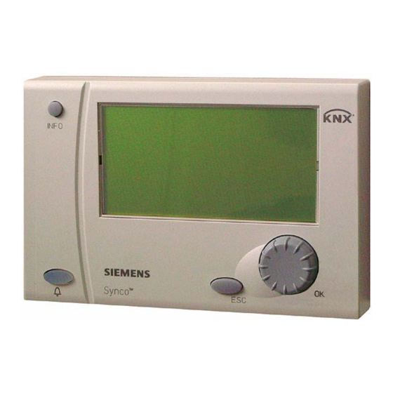
Synco 700 bus operator unit
Hide thumbs
Also See for Synco RMZ792:
- Basic documentation (58 pages) ,
- Installation instructions manual (16 pages) ,
- Installation instructions manual (16 pages)

Related Manuals for Siemens Synco RMZ792


Summary of Contents for Siemens Synco RMZ792
- Page 1 ™ Synco Bus Operator Unit RMZ792 Basic Documentation Edition 1.0 Series A Building Technologies CE1P3113en HVAC Products 03.04.2006...
- Page 2 Siemens Switzerland Ltd © 2006 Siemens Switzerland Ltd Building Technologies Group Subject to alteration International Headquarters HVAC Products Gubelstrasse 22 CH- 6301 Zug Tel. +41 41 724 24 24 Fax +41 41 724 35 22 www.sbt.siemens.com 2/52 Building Technologies Bus operator unit RMZ792...
-
Page 3: Table Of Contents
Contents Summary ......................7 Bus operator unit RMZ792 ................7 Operator units....................7 Topology of Synco™ 700 ................8 Product documentation..................8 Key features ....................9 Important notes....................10 Operation....................... 11 Functions of the bus operator unit ..............11 Operating concept ..................11 Operating levels..................... - Page 4 Activating communication ................22 6.2.1 Submenu “Communication” ................22 Device list.......................23 6.3.1 Submenu “Create list” ..................24 6.3.2 Submenu “Sort list” ..................24 6.3.3 Submenu “Name devices” ................25 6.3.4 Submenu “Add devices”.................26 6.3.5 Submenu “Delete devices”................26 6.3.6 Submenu “Delete list” ..................26 6.3.7 Submenu “Display list” ...................27 6.3.8 Submenu “List information”................27 Favorites ......................27...
- Page 5 10.1.1 Device list on the “Main menu” ..............41 10.1.2 Menu “Faults current” ..................41 10.1.3 Info page and menu “Fault status message bus” .......... 41 10.2 Faults of non-listed bus users................ 41 10.3 Acknowledgement of faults................42 10.4 Resetting faults....................42 10.5 Deleting faults....................
- Page 6 6/52 Building Technologies Bus operator unit RMZ792 CE1P3113en HVAC Products Contents 03.04.2006...
-
Page 7: Summary
Summary Bus operator unit RMZ792 What is the RMZ792 The RMZ792 is a communicating operator unit designed for operating Synco™ 700 bus operator unit? devices in a Konnex network. The operator unit is suited both for fixed installation and mobile use (e.g. for use by the service engineer). Third-party devices cannot be operated with it. -
Page 8: Topology Of Synco™ 700
Name Illustration Function Type Data reference Sheet no. Operator Local operation for RMZ791 N3112 unit, de- commissioning, ser- tached vice and users Service and PC software for com- OCI700.1 N5655 operator unit missioning, service and users Topology of Synco™ 700 Use of the RMZ792 bus The illustration below shows a typical topology for using the RMZ792 bus operator unit: operator unit... -
Page 9: Key Features
Type of document Document no. Data Sheet “Bus Operator Unit RMZ792” N3113 Installation Instructions “Bus Operator Unit RMZ792” G3113 Environmental Declaration “Bus Operator Unit RMZ792” E3113 Product range description “HVAC controllers with Konnex interface” S3110 Basic Documentation “Communication with Konnex bus” P3127 Data Sheet “Konnex bus KNX”... -
Page 10: Important Notes
Faults Should system faults occur and you are not authorized to make diagnostics and to rectify faults, call your Siemens customer service. Only authorized staff are permitted to make diagnostics, to rectify faults and to restart the plant. This also applies to work carried out within the control panel (e.g. safety checks or replacement of fuses). -
Page 11: Operation
Operation Synco™ 700 devices may only be operated by staff who have been instructed by SBT HVAC Products or their delegates and whose attention has been drawn to potential risks. Functions of the bus operator unit The RMZ792 bus operator unit is used to make all settings and readouts required for operating a device. -
Page 12: Operating Levels
Display examples Start page Device list, partly with fault symbol Pop-up, setting a numerical value Help picture with explanations relating to the selected setting parameter Operating levels The following operating levels are available: Level Icon Description On the info level, important plant data (fault and service Info level information) can be retrieved and displayed. -
Page 13: Menu Tree
Level Icon Description The password level displays additional menus and data- Password level points for configuring and commissioning the bus opera- tor unit. The password level is protected by a password to prevent unauthorized access. The unit comes standard with number “7” as the password. From this level, the password level of the bus users cannot be accessed;... - Page 14 The datapoints can be displayed or changed. Optionally, the menus can be pro- tected by a password (user level) to prevent unauthorized access. 3. Local menus: All settings of the bus operator unit are made on the local menus. The settings are not valid for bus users on the device list.
-
Page 15: Operation Of Devices
Operation of devices Product range The RMZ792 bus operator unit is used for operating the following devices of the Synco™ family (situation February 2006): Type of unit Type reference Data Sheet no. Central control unit RMB795… N3121 Heating controllers RMH760… N3131 and N3133 Boiler sequence controller RMK770…... -
Page 16: Quick Access With Favorites
• The device name and – if appropriately set – the device address • The current position in the menu tree (path) • Long text relating to the selected datapoint The information is displayed as long as the button is kept depressed. Quick access with favorites The favorite pages provide a user interface matched to the requirements of every day use. -
Page 17: User-Defined Text
Error / error message Cause / remedy • Communication with target device is not Caution! Device not responding possible • Is the device in operation? • Is the device connected to the Konnex bus? • Has the device address been changed? Datapoint shows a value that does The device does not support information not make sense (e.g. -
Page 18: Power Supply
Power supply The bus operator unit can be powered in 3 different ways: • Via Konnex bus (45 mA) • Via an external power source (AC 24 V) • Via the service interface of a Synco™ controller (not recommended) • When using the cable supplied with the bus operator unit, plug correctly the RJ45 Notes connector into the appropriate socket of the RMZ792 (audible click) •... -
Page 19: Power Supply Via Synco™ Controller
Power supply via Synco™ controller • In exceptional cases, the bus operator unit can also be powered via the service interface of a Synco™ controller. Because of the additional power consumption of the bus operator unit, this type of power supply is possible only if the controller is equipped with no more than 3 extension modules •... -
Page 20: Commissioning
Commissioning Preparation for use and commissioning of Synco™ 700 devices must be under- taken by qualified staff who have been appropriately trained by SBT HVAC Prod- ucts or their delegates. Entering the commissioning mode 5.1.1 Entry on first startup When supplying power to the bus operator for the first time, the Language menu ap- pears. -
Page 21: "Commissioning" Menu
“Commissioning” menu • Prerequisite for trouble-free operation of the bus operator unit is correct assignment Important! of the device addresses of all bus users including the line couplers • The device addresses of all bus users and line couplers must accord with their positions in the network topology (area.line.address). -
Page 22: Error Handling
6.1.4 Error handling Possible cases Error Cause / remedy No communication with other bus users The device address is 255, which means that communication is not active. Set the device address to a value be- tween 1 and 252 (automatic search or manual predefinition). -
Page 23: Device List
Device list Definition The device list is the list containing the bus users that can be operated. The system switches from the device list of the bus operator unit to the menu tree of the bus user. Bus users that do not appear on the device list cannot be operated via the bus operator unit. Presentation Bus users are presented on the device list as follows: Information... -
Page 24: Submenu "Create List
Status messages Description Device list has been successfully Sorted sorted Device list has been successfully Deleted deleted Device search not possible with the Sorted current settings of area and line 6.3.1 Submenu “Create list” • When the bus operator unit is connected to plant for the first time •... -
Page 25: Submenu "Name Devices
Main menu > Commissioning > Device list > Sort list Operating lines Operating line Range Factory setting Sort automatically by Device addresses / Device names Sort manually The device list can be sorted either manually or automatically according to predefined criteria. -
Page 26: Submenu "Add Devices
6.3.4 Submenu “Add devices” • Adding an individual device to the device list • Adding devices from some other area to the device list • Adding devices from some other line to the device list • Updating the device list Main menu >... -
Page 27: Submenu "Display List
6.3.7 Submenu “Display list” • Changing the display format of the device list • Showing the device address on the device list or hiding it Main menu> Commissioning > Device list > Display list Operating lines Operating line Range Factory setting Type of display Address and name / Address and... -
Page 28: Submenu "Add Datapoints
• Adding favorite pages and datapoints • Naming the favorite pages (titles) • Renaming the names of the datapoints • Sorting the favorite pages • Deleting datapoints and entire favorite pages • To improve readability, it is recommended to give the favorite pages self-explanatory Notes names •... -
Page 29: Submenu "Name Datapoints
• A datapoint has been successfully assigned to a favorite page • Navigation to the start page (press ESC buttons several times, or long press) • Navigation to the Commissioning menu • Navigation to the Favorites menu • Navigation to the Favorite pages menu •... -
Page 30: Submenu "Delete Datapoints
shifted to the required position. The position of each page can be freely selected (1 = first page presented, 20 = last page presented). If the required position lies beyond the current end of the list, the page will be placed in the last position. •... -
Page 31: Submenu "Delete All Favorites
6.4.7 Submenu “Delete all favorites” Deleting all favorite pages. Main menu > Commissioning > Favorite pages > Delete all favorites Operating lines Operating line Range Factory setting Delete all favorites --- / Deleted After a security check is made, all favorite pages with their titles and all their datapoints will be deleted. -
Page 32: Data Backup
Data backup • Making a backup copy of the settings • Restoring the safe settings after unsuccessful changes • Securing or restoring the settings when changing the memory card Function When commissioning is completed, the settings of the bus operator unit can be saved. Later –... -
Page 33: Data Backup On A Second Unit
Storage date and Storage year only show sensible values if the bus operator unit received Note a valid system time at the time of data backup. Data backup on a second unit General Before the settings can be saved on a second bus operator unit, that unit must be installed on the bus and be fully functioning. -
Page 34: Error Handling
Error handling Possible cases Error Cause / remedy • Invalid address of the second unit Save Failed • Communication breakdown to the second Progress ---- % unit Remedy: Setting not saved • Check bus connection and address of the second unit •... -
Page 35: General Settings
General settings Time of day and date Yearly clock The bus operator unit does not have its own yearly clock. If some other bus user (clock time master) sends the time of day, the weekday and the date, that information will be adopted and displayed by the bus operator unit. -
Page 36: Error Handling
8.1.3 Error handling Possible cases Error Cause / remedy • In the system, bus users do not send the Time of day, weekday and date are not shown on the start menu system time (there is no clock time master) •... -
Page 37: Selecting The Unit Of Temperature
• With the bus operator unit, it is also possible to change the language of a bus user (Synco™ 700 controllers type RMx7…). The language is selected via the device list on the respective menu of the bus user. If the selected language does not exist with the bus user, a change to English is made. -
Page 38: Password
Password Each of the 3 operating levels (User level, Service level and Expert level) can be protected against unauthorized access through the use of passwords. The expert level is the password level used by the bus operator unit. For the bus operator unit, the terms “Password level”... -
Page 39: Device Information
Device information Menu Device information provides information about the current version of the bus opera- tor unit. Main menu > Device > Device information Displays Operating line Remarks Software version Display of type reference of bus operator unit (RMZ792) Software version Display of software version of bus operator unit Hardware version... -
Page 40: Faults
Faults As a matter of principle, the bus operator unit only handles faults of devices contained on the device list. When starting up, it can take up to 3 minutes for the device fault information to be updated, depending on the size of the device list. When using network topologies with line couplers, it must be made certain that the line couplers forward correctly the devices’... -
Page 41: 10.1.1 Device List On The "Main Menu
10.1.1 Device list on the “Main menu” The fault state of the devices is shown on the main menu by a symbol on the right hand side. The symbols have the following meaning: Fault symbol Description Device in order, no fault pending Device faulty Device reads information about the fault Possibility of device failure, information about fault cannot be read... -
Page 42: Acknowledgement Of Faults
• Setting Device list only: Fault status messages from non-listed bus users will be ignored. • Setting All devices: If, at present, the fault status message from a non-listed bus user is the most severe pending, it will only appear on the menu and on info page Fault status message bus. The fault LED will not be lit. -
Page 43: Memory Card
Memory card 11.1 Content of memory card The exchangeable RMA792 memory card contains text catalogs in different languages and the device descriptions of the bus users. The version of the bus user and that of the respective device description must accord. For new versions or new types of Syn- co™... -
Page 44: Support In The Event Of Errors And Faults
Support in the event of errors and faults 12.1 Error code list The list only covers the errors that can result from the connection and operation of the bus operator unit. For notes relating to other error codes, refer to the descriptions of the respective devices. - Page 45 Error / error message Cause / remedy During commissioning, the wrong language 1. Press simultaneously the ESC was selected. How do I find “my” language? button and the OK knob. 2. Select the password level, enter 112 as the password (same no. as international emergency call) and confirm by pressing the OK knob.
-
Page 46: Electrical Connections
Electrical connections Connection terminals for AC 24 V operating voltage G, G0 Connection terminals for Konnex bus data line (positive) CE− Connection terminals for Konnex bus data line (negative) Socket for Konnex bus (RJ45) Slide switch for selecting the type of power supply KNX: Power supply via Konnex bus (45 mA) EXT: External power supply via G, G0 (AC 24 V) Note... -
Page 47: Appendix
Appendix 14.1 Abbreviations used in this document The following list contains the abbreviations most frequently used (in alphabetical order): Abbreviation Meaning Alternating Current ACS7… commissioning and operating software European Installation Bus (will be replaced by Konnex) Engineering Tool Software (Konnex / EIB) Konnex bus connection (for operation and process information) LTE mode New communication standard used by Synco and RXB... - Page 48 Main menu > Commissioning > Favorite pages > Name favorites Name of datapoint User-defined text Favorite title 1 Favorite title 2 Favorite title 3 Favorite title 4 Favorite title 5 Favorite title 6 Favorite title 7 Favorite title 8 Favorite title 9 Favorite title 10 …...
- Page 49 Index display faults .............41 display format type of display........27 abbreviations............. 47 display of bus fault status message ......37 acknowledge faults ........... 42 display of faults ............40 acknowledgement of faults ........42 display the device list ..........27 ACS................47 activating communication.......... 22 add devices...............
- Page 50 second unit for data backup ........33 manual assignment of addresses......21 select-and-press knob ..........11 memory card ............7, 43 selecting the language........20, 36 menu tree ............12, 13 service level............12, 38 setting the time of day ..........35 S-mode ..............47 name datapoints............29 SNA ................
- Page 51 51/52 Building Technologies Bus operator unit RMZ792 CE1P3113en HVAC Products 03.04.2006...
- Page 52 Siemens Switzerland Ltd © 2006 Siemens Switzerland Ltd Building Technologies Group Subject to alteration International Headquarters HVAC Products Gubelstrasse 22 CH- 6301 Zug Tel. +41 41 724 24 24 Fax +41 724 35 22 www.sbt.siemens.com 52/52 Building Technologies Bus operator unit RMZ792...