
Related Manuals for Siemens SIRIUS 3RT Series


Summary of Contents for Siemens SIRIUS 3RT Series
- Page 1 SIRIUS Innovations System Manual 01/2011 • Industrial Controls Answers for industry.
-
Page 3: System Manual, 01/2011, A8E56203870002
___________________ SIRIUS Innovations System overview SIRIUS 3RT2 contactors/contactor assemblies ___________________ SIRIUS 3RF34 solid-state switching devices Industrial controls SIRIUS 3RV2 motor starter ___________________ protectors SIRIUS Innovations ___________________ SIRIUS 3RU2/3RB3 overload relays ___________________ SIRIUS 3RA21/22 load feeders System Manual SIRIUS 3RA28 function modules for mounting on 3RT2 contactors ___________________... - Page 4 Note the following: WARNING Siemens products may only be used for the applications described in the catalog and in the relevant technical documentation. If products and components from other manufacturers are used, these must be recommended or approved by Siemens. Proper transport, storage, installation, assembly, commissioning, operation and maintenance are required to ensure that the products operate safely and without any problems.
-
Page 5: Table Of Contents
Table of contents System overview............................19 Introduction ..........................19 1.1.1 Modular system for SIRIUS ......................19 1.1.2 SIRIUS Innovations........................20 Safety instructions........................22 Standards and approvals ......................23 1.3.1 Standards.............................23 1.3.2 Approvals, test certificates, characteristics..................24 Overview ............................25 1.4.1 SIRIUS modular system.......................25 1.4.2 Content of SIRIUS Innovations System Manual ................27 System properties ........................28 1.5.1 System properties ........................28... - Page 6 Table of contents Mounting and disassembly......................72 1.8.1 Screw mounting .......................... 72 1.8.2 Snap-on mounting........................72 Connection ..........................74 1.9.1 Connection systems........................74 1.9.1.1 Screw connection........................74 1.9.1.2 Spring-loaded connection ......................75 1.9.1.3 Ring cable lug connection ......................79 1.9.2 Conductor cross-sections......................
- Page 7 Table of contents 2.4.5 Switching resistive loads......................124 2.4.6 Changing the polarity of hoisting gear motors ................125 2.4.7 Switching in the auxiliary circuit ....................126 2.4.8 Contactors with extended operating range ................127 2.4.8.1 Overview ............................127 2.4.8.2 Contactors with UC drive ......................127 2.4.8.3 Contactors for railway applications ....................128 2.4.8.4 Coupling relays ..........................130...
- Page 8 Table of contents 2.7.10.2 Mounting............................ 192 2.7.11 Solder pin adapter........................193 2.7.11.1 Description ..........................193 2.7.11.2 Mounting............................ 194 2.7.12 Coil terminal module ......................... 195 2.7.12.1 Description ..........................195 2.7.12.2 Mounting............................ 196 2.7.13 Cover for ring cable lug ......................197 2.7.13.1 Description ..........................197 2.7.14 Sealable cover ..........................
- Page 9 Table of contents 2.8.1.10 Rated data for auxiliary contacts (CSA and UL) ................251 2.8.1.11 Main circuit - 3RT202. contactors (current carrying capacity for direct current)......252 2.8.1.12 Conductor cross-sections - 3RT202. contactors................254 2.8.1.13 Rated data (CSA and UL) for 3RT201. and 3RT202. contactors ..........256 2.8.2 Contactors for specific applications (3RT23 and 3RT25) ............258 2.8.2.1...
- Page 10 Table of contents Planning/configuring........................329 3.5.1 Selecting solid-state switching devices..................329 3.5.2 Configuration: Selecting solid-state contactors for motors ............330 3.5.3 Short-circuit protection ......................334 3.5.3.1 Mounting accessories for the load feeder conforming to IEC ........... 334 3.5.3.2 Mounting accessories for the load feeder conforming to UL ............ 336 Application planning ........................
- Page 11 Table of contents SIRIUS 3RV2 motor starter protectors....................379 Standards...........................379 Product description ........................380 4.2.1 Introduction ..........................380 4.2.2 Versions .............................381 4.2.3 Applications..........................382 4.2.4 Motor starter protectors......................383 4.2.5 Performance features ........................384 Product combinations ........................385 Functions............................386 4.4.1 Overload and short-circuit protection..................386 4.4.1.1 Tripping classes .........................387 4.4.1.2 Tripping characteristics ......................388 4.4.2...
- Page 12 Table of contents 4.9.3 Auxiliary switch.......................... 410 4.9.3.1 Description ..........................410 4.9.3.2 Mounting............................ 411 4.9.3.3 Disassembly..........................412 4.9.4 Signaling switch ........................413 4.9.4.1 Description ..........................413 4.9.4.2 Mounting............................ 414 4.9.4.3 Disassembly..........................414 4.9.4.4 Operation and diagnostics ......................415 4.9.5 Auxiliary release........................416 4.9.5.1 Description ..........................
- Page 13 Table of contents 4.10.6 Auxiliary switches, lateral and signaling switches..............457 4.10.7 Auxiliary releases........................458 4.10.8 Short-circuit protection for auxiliary and control circuits ............458 4.10.9 Conductor cross-sections main circuit ..................459 4.10.10 Conductor cross-sections auxiliary and control circuits .............460 4.10.11 Short-circuit breaking capacity....................462 4.10.11.1 Short-circuit breaking capacity for motor starter protectors..........462 4.10.11.2...
- Page 14 Table of contents Connection ..........................513 5.7.1 Connection of 3RU21 overload relay ..................514 5.7.2 Connection of 3RB30/3RB31 overload relays ................515 Operation........................... 516 5.8.1 Setting the current........................516 5.8.2 Setting the tripping class/ground-fault detection (3RB31) ............517 5.8.3 RESET after release ......................... 517 5.8.4 TEST function ...........................
- Page 15 Table of contents SIRIUS 3RA21/22 load feeders ......................563 Standards...........................563 Product description ........................564 6.2.1 Overview ............................564 6.2.2 Device versions..........................564 6.2.2.1 Pre-assembled complete devices ....................566 6.2.2.2 Self-assembled load feeders .....................567 6.2.3 Applications..........................568 6.2.4 Application environment......................568 Product combinations ........................569 Functions............................570 Configuration..........................571 Mounting ............................572 6.6.1 Installation guidelines.........................572 6.6.1.1...
- Page 16 Table of contents SIRIUS 3RA28 function modules for mounting on 3RT2 contactors ............641 Standards ..........................641 Product description ........................642 7.2.1 Device versions......................... 643 7.2.2 Performance features........................ 645 7.2.3 Applications..........................646 7.2.3.1 Function modules for direct-on-line start................... 646 7.2.3.2 Function modules for star-delta (wye-delta) start ..............
- Page 17 Table of contents SIRIUS 3RR2 current monitoring relays ....................683 Standards...........................683 8.1.1 Standards...........................683 Product description ........................684 8.2.1 Introduction ..........................684 8.2.2 Versions .............................685 8.2.3 Applications..........................685 8.2.4 The advantages of current monitoring relays ................686 8.2.5 3RR214.-.A.30 Basic analog setting current monitoring relay...........687 8.2.6 3RR224.-.F.30 Standard digital setting current monitoring relay..........688 Product combinations ........................689...
- Page 18 Table of contents Accessories ..........................729 8.9.1 Accessories ..........................729 8.9.2 Terminal support for stand-alone assembly................729 8.9.2.1 Description ..........................729 8.9.2.2 Mounting............................ 730 8.9.3 Sealable cover .......................... 732 8.9.3.1 Description ..........................732 8.9.3.2 Mounting............................ 732 8.10 Technical data........................... 733 8.10.1 Performance features of current monitoring relays..............
-
Page 19: System Overview
The process of configuring control cabinets must be quick, easy, flexible, and must enable you to create space-saving solutions. This is exactly what Siemens offers with its unique SIRIUS modular system. This system offers all the functions and devices you will need for switching, starting, protecting, and monitoring motors and systems. -
Page 20: Sirius Innovations
Siemens is constantly developing its product portfolio to enable it to meet the demands of industry, not only today, but in the future too. As part of this process, Siemens gathers customer feedback on an ongoing basis and considers it in conjunction with the global trends of tomorrow. - Page 21 Minimized planning and configuration outlay In order to reduce the effort involved in planning and configuration to a minimum, Siemens offers a range of Internet tools in addition to the standard documents in paper format. These tools can help you to select the most suitable product for your needs, to find the associated technical data quickly, and to put together the relevant technical documentation easily.
-
Page 22: Safety Instructions
System overview 1.2 Safety instructions Safety instructions Five safety rules for work in or on electrical installations A set of rules, which are summarized in DIN VDE 0105 as the "five safety rules", are defined for work in or on electrical installations as a preventative measure against electrical accidents: 1. -
Page 23: Standards And Approvals
System overview 1.3 Standards and approvals Standards and approvals 1.3.1 Standards The standards from Catalog LV 1 "Low-Voltage Controls and Distribution SIRIUS - SENTRON - SIVACON" in the appendix always apply. Below are some of the most important standards which apply to the innovations to the SIRIUS modular system. Standards Table 1- 1 IEC/DIN EN/DIN VDE standards... -
Page 24: Approvals, Test Certificates, Characteristics
You can find an overview of the certifications available for low-voltage controls and distribution products and other technical documentation, updated daily, on the Internet (http://www.siemens.com/lowvoltage/support). For further information, refer to Catalog LV1 "Low-Voltage Controls and Distribution SIRIUS - SENTRON - SIVACON", Chapter 20. -
Page 25: Overview
System overview 1.4 Overview Overview 1.4.1 SIRIUS modular system SIRIUS modular system The SIRIUS product range comprises devices for use in switching, starting, protecting, and monitoring, as well as combinations thereof, which are known as "load feeders". Load feeders can be created from the following devices: ●... - Page 26 System overview 1.4 Overview Size Function Components Main circuit Switching Contactors and starting Solid-state switching devices Soft starters Protecting Motor starter protectors Overload relays Monitoring Current monitoring relays Feeders Feeders Compact starters Control circuit Function modules for mounting on contactors Function modules for connection to the automation level...
-
Page 27: Content Of Sirius Innovations System Manual
Chapter 3 "SIRIUS 3RF4 solid-state switching devices (Page 313)" 3RW soft starters Manual "SIRIUS 3RW30/3RW40 Soft Starters" (http://support.automation.siemens.com/WW/vi ew/en/38752095) (order no.: 3ZX1012-0RW30-1AC1) Manual "SIRIUS 3RW44 Soft Starters" (http://support.automation.siemens.com/WW/vi ew/en/21772518) (order no.: 3ZX1012-0RW30-1AC1) 3RV2 motor starter protectors Chapter 4 "SIRIUS 3RV2 motor starter... -
Page 28: System Properties
System overview 1.5 System properties Reference You can download the manuals from the Internet (www.siemens.com/lowvoltage/support). Simply enter the order number of the relevant item into the search field. Notes on further information (product information, product documentation, product selection, etc.) available on the Internet can be found in the "More information (Page 758)" appendix. -
Page 29: Modular System Design
System overview 1.5 System properties 1.5.2 Modular system design The individual SIRIUS Innovations components are modules from the complete SIRIUS modular system (up to size S12, 250 kW at 400 V), which are matched to one another in terms of their size and their technical data. This enables individual requirements to be met quickly and cost-effectively. -
Page 30: Switching Technology
System overview 1.5 System properties 1.5.3 Switching technology The SIRIUS modular system has the right technology for every application: Table 1- 3 Motor starting options Application Technology Direct-on-line start 3RT contactors, 3RA contactor Electromechanical assemblies, or 3RA6 compact starters starting Reversing start 3RA reversing contactor assemblies... - Page 31 System overview 1.5 System properties Example: 3RW soft starters 3RW soft starters are used for soft starting and ramp-down, for pumps and fans, for example. α α α ϕ α Figure 1-5 Phase angle control of the thyristor pairs Technology selection depends on various factors. The table below provides an overview of the most important aspects: Table 1- 4 Technology selection...
-
Page 32: Uniform Connection System
System overview 1.5 System properties 1.5.4 Uniform connection system The devices are matched to one another in terms of their rated sizes and technical data. ● The same width guarantees quick mounting. ● Devices with the same rated current have the same terminals. ●... -
Page 33: Flexible Assembly Methods
System overview 1.5 System properties 1.5.5 Flexible assembly methods The SIRIUS modular system offers maximum flexibility in terms of configuration. The system components can be assembled as feeders or mounted separately. Table 1- 6 Assembly (mounted separately or assembled as feeders) Separately mounted Mounted as complete feeders The system components are assembled... -
Page 34: Assembly And Mounting
Accessories such as auxiliary switches and surge suppressors can be mounted quickly and disassembled in just a few short steps. Standard tools are required to disassemble components only very rarely. Siemens offers a standardized tool (screwdriver 3RA2908-1A) for disassembling conductors from spring-loaded terminals on all SIRIUS Innovations products. - Page 35 System overview 1.5 System properties The link module is first attached to the device to be connected, then the resulting unit is plugged on to the motor starter protector. This ensures that the requisite electrical and mechanical connections are established in the main circuit. Overload relays and current monitoring relays can easily be attached to contactors and solid-state switching devices in a similar way, without the need for another link module: Current monitoring relay...
-
Page 36: Application Monitoring
System overview 1.5 System properties 1.5.9 Application monitoring The current monitoring relays, which enable intelligent protective functions to be easily implemented within the application, are a central component of the innovations made to the SIRIUS modular system. Increasing numbers of customers require application monitoring in addition to motor protection. -
Page 37: Communication
● IO-Link ● AS-Interface SIRIUS switching devices are linked into the Siemens Totally Integrated Automation concept via function modules. Totally Integrated Automation offers the user uniformity in terms of configuration, programming, data storage, and communication. -
Page 38: Safety Applications
PL e (ISO 13849-1) or SIL 3 (IEC 62061) 1.5.12 Environmental protection Siemens attaches great importance to the subject of eco-design. Our company-internal standard SN 36350 on environmentally compatible product design has been permanently integrated in our product development processes since 1993. Our production meets the highest quality and environmental standards. - Page 39 System overview 1.5 System properties Product example contactors ● Minimized holding and closing power. – The aspects of low power loss and further optimization of the holding and closing power ratings played an important role in the development of SIRIUS contactors. –...
-
Page 40: Customer Benefits
System overview 1.6 Customer benefits Customer benefits Customer benefits SIRIUS offers benefits in the following areas: ● Assembly and handling ● Planning and configuration ● Connection to the automation level ● System monitoring Table 1- 8 Customer benefits Area Technical highlights Customer benefits Proven and optimized modularity and Maximum flexibility for... - Page 41 System overview 1.6 Customer benefits SIRIUS offers the perfect solution throughout the entire product lifecycle: Figure 1-10 Customer benefits by product lifecycle SIRIUS Innovations System Manual, 01/2011, A8E56203870002-03...
-
Page 42: Components And Combinations
System overview 1.7 Components and combinations Components and combinations 1.7.1 Switching and starting 1.7.1.1 SIRIUS 3RT2 contactors 3RT2 contactors Figure 1-11 S0 contactor SIRIUS 3RT2 contactors and contactor assemblies offer maximum flexibility in terms of dimensioning, handling, and function: Table 1- 9 3RT2 contactors and contactor assemblies Area Customer benefits... - Page 43 System overview 1.7 Components and combinations Area Customer benefits Easy connection of feeders to the automation level via AS-Interface or IO- Application Link areas/customer benefits Performance increase up to 18.5 kW in 45 mm width Safety applications: Motor starter protectors in combination with ...
- Page 44 System overview 1.7 Components and combinations Fitting of auxiliary switches on 3RT2 contactors (size S00 and S0) Contactor size S00 Contactor size S0 Laterally mountable auxiliary switch block (right or left), 2-pole Auxiliary switch block for snapping onto the front, 4-pole Auxiliary switch block for snapping onto the front, 2-pole (cable entry from above) Auxiliary switch block for snapping onto the front, 2-pole (cable entry from below) Auxiliary switch block for snapping onto the front, 1-pole (cable entry from above or below)
- Page 45 System overview 1.7 Components and combinations Size-specific accessories for 3RT2 contactors (size S00) Contactor size S00 Laterally mountable auxiliary switch block (right or left), 2-pole Auxiliary switch block for snapping onto the front, 1-pole (cable entry from above or below) Auxiliary switch block for snapping onto the front, 2-pole (cable entry from above or below) Auxiliary switch block for snapping onto the front, 4-pole 3RA28 function modules...
- Page 46 System overview 1.7 Components and combinations Size-specific accessories for contactors (size S0) Contactor size S0 Laterally mountable auxiliary switch block (right or left), 2-pole Auxiliary switch block for snapping onto the front, 1-pole (cable entry from above or below) Auxiliary switch block for snapping onto the front, 4-pole Auxiliary switch block for snapping onto the front, 2-pole (cable entry from above or below) Surge suppressor Function module for AS-Interface, direct-on-line start...
- Page 47 System overview 1.7 Components and combinations Parallel switching connector Terminal module (adapter) for contactors with screw connections Coil terminal module, top and bottom Wiring modules, top and bottom, for connecting the control current paths Wiring modules, top and bottom, for connecting the main current paths Star jumper, 3-pole, without connection terminal 3-phase infeed terminal Figure 1-14...
-
Page 48: Sirius 3Rf34 Solid-State Switching Devices
System overview 1.7 Components and combinations 1.7.1.2 SIRIUS 3RF34 solid-state switching devices 3RF34 solid-state switching devices Figure 1-15 Solid-state switching device SIRIUS 3RF34 solid-state switching devices feature a heat sink integrated in the insulated enclosure, so no grounding is required. Table 1- 10 3RF34 solid-state switching devices Area... -
Page 49: Sirius 3Rw30/40 Soft Starters
Integrated diagnostics functions (3RW40) Comprehensive approvals for global applicability, also ATEX (3RW40) Reference More information ... Is available in ... About SIRIUS 3RW30/40 soft starters Manual "SIRIUS 3RW30/3RW40 Soft Starters" (http://support.automation.siemens.com/WW/view /en/38752095) (order no.: 3ZX1012-0RW30-1AC1) SIRIUS Innovations System Manual, 01/2011, A8E56203870002-03... - Page 50 System overview 1.7 Components and combinations Accessories for 3RW30 soft starters Link module to motor starter protector with screw-type terminals Link module to motor starter protector with spring-loaded terminals (size S0) Link module to motor starter protector with spring-loaded terminals (size S00) Infeed terminal (sizes S00 and S0) Figure 1-17 Accessories for 3RW30 soft starters...
-
Page 51: Protecting
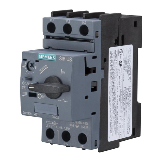
System overview 1.7 Components and combinations 1.7.2 Protecting 1.7.2.1 SIRIUS 3RV2 motor starter protectors 3RV2 motor starter protectors Figure 1-19 Motor starter protector S0 SIRIUS 3RV2 motor starter protectors can be combined with other SIRIUS devices easily and flexible, while also saving on space and wiring: Table 1- 12 3RV2 motor starter protectors Area... - Page 52 System overview 1.7 Components and combinations Accessories for 3RV2 motor starter protectors Signaling switch Lateral auxiliary switch with 2 contacts Lateral auxiliary switch with 4 contacts Disconnector module Terminal block type E Undervoltage release Shunt release Transverse auxiliary switch Figure 1-20 Accessories for 3RV2 motor starter protectors SIRIUS Innovations System Manual, 01/2011, A8E56203870002-03...
- Page 53 System overview 1.7 Components and combinations Infeed systems The SIRIUS modular system has the right infeed for every requirement. SIRIUS infeed system (3RV2917) 3-phase busbar system (3RV1915) Combination of 3RA68 infeed system for compact starter and 3RV2917 infeed system for motor starter protector Busbar system (8US) Figure 1-21 Infeed systems...
-
Page 54: Sirius 3Rv2917 Infeed System
System overview 1.7 Components and combinations 1.7.2.2 SIRIUS 3RV2917 infeed system 3RV2917 infeed system 3-phase busbar with infeed 3-phase busbar for system expansion Expansion plug End cap Connector Contactor base Outgoing terminal Figure 1-22 3RV2917 infeed system SIRIUS Innovations System Manual, 01/2011, A8E56203870002-03... -
Page 55: Sirius 3Ru2/3Rb3 Overload Relays
System overview 1.7 Components and combinations 1.7.2.3 SIRIUS 3RU2/3RB3 overload relays 3RU2/3RB3 overload relays Figure 1-23 S0 overload relay The thermal and solid-state overload relays are available in the modular system with graded functionality, which reflects their flexible applicability. Table 1- 13 3RU2/3RB3 overload relays Area Customer benefits... - Page 56 System overview 1.7 Components and combinations Accessories for 3RU2 and 3RB30/31 overload relays Overload relay size S0 Overload relay size S00 Stand-alone assembly support, size S0 Stand-alone assembly support, size S00 Electrical remote reset, sizes S00 and S0 (3RU2 only) Sealing cover, sizes S00 and S0 Figure 1-24 Accessories for 3RU2 and 3RB30/31 overload relays...
-
Page 57: Monitoring
System overview 1.7 Components and combinations 1.7.3 Monitoring 1.7.3.1 SIRIUS 3RR2 current monitoring relays 3RR2 current monitoring relays Figure 1-25 S0 current monitoring relays The SIRIUS 3RR2 current monitoring relays are ideally suited to a range of applications, thanks to the flexible way in which they can be adjusted: Table 1- 14 3RR2 current monitoring relays Area... - Page 58 System overview 1.7 Components and combinations Reference More information ... Is available in ... About SIRIUS 3RR2 current monitoring relays Chapter 8 "SIRIUS 3RR2 current monitoring relays (Page 683)" Accessories for 3RR2 current monitoring relays 3RR21 current monitoring relays 3RR22 current monitoring relays Stand-alone mounting support Sealing cover Figure 1-26...
-
Page 59: Feeders
System overview 1.7 Components and combinations 1.7.4 Feeders 1.7.4.1 SIRIUS 3RA21/22 load feeders Load feeders Figure 1-27 S0 load feeder The tested load feeders offer switching and protection functions. Thanks to their multiple combination options, they can be easily configured for almost any requirement. Table 1- 15 Load feeders Area... - Page 60 System overview 1.7 Components and combinations Accessories for load feeders The main accessories for 3RV2 motor starter protectors, and those for 3RT2 contactors (such as side-mounted and transverse auxiliary switches, current limiters, undervoltage limiters, rotary operating mechanisms, busbar adapters, etc.) can be used for 3RA21/22 load feeders and feeders for self-assembly.
-
Page 61: Sirius 3Ra6 Compact Starters
System overview 1.7 Components and combinations 1.7.4.2 SIRIUS 3RA6 compact starters 3RA6 compact starter Figure 1-28 Compact starter The SIRIUS 3RA6 compact starter is a compact, highly integrated device which features state-of-the-art controls, including practical diagnostics functions. The compact starter ensures improved efficiency and reliability in the control cabinet. - Page 62 Compact starter reversing version Compact starter direct-on-line, IO-Link version Compact starter reversing, IO-Link version Reference More information ... Is available in ... About the 3RA6 compact starter Manual "SIRIUS 3RA6 Compact Starter" (http://support.automation.siemens.com/WW/view /en/27865747) (order no.: 3RA6992-0A) SIRIUS Innovations System Manual, 01/2011, A8E56203870002-03...
- Page 63 System overview 1.7 Components and combinations Accessories for 3RA6 compact starters 3RA6 compact starter External auxiliary switch block AS-i add-on module AS-i add-on module with: Two local inputs for safe disconnection Two additional digital inputs One additional digital input and one digital output ...
- Page 64 System overview 1.7 Components and combinations Infeed system for 3RA6 compact starter Infeed on left or right using spring-loaded connection system Infeed on left using screw-type connection system Expansion module Expansion plug Terminal block Expansion plug for 3RV19 PE infeed PE expansion plug PE tap 45 mm adapter for infeed system for 3RA6...
-
Page 65: Function Modules
System overview 1.7 Components and combinations 1.7.5 Function modules Figure 1-31 Function modules Function modules are used to perform various control jobs on automatic production lines and for processing machines. They are suited to all time-delayed switching operations in control, starting, protection, and regulation circuits, and ensure a high degree of repeat accuracy for delay times, once they have been set. -
Page 66: Sirius 3Ra28 Function Modules For Mounting On Sirius 3Rt2 Contactors
System overview 1.7 Components and combinations 1.7.5.1 SIRIUS 3RA28 function modules for mounting on SIRIUS 3RT2 contactors 3RA28 function modules for mounting on 3RT2 contactors SIRIUS 3RA28 function modules for mounting on SIRIUS 3RT2 contactors enable the control circuit wiring to be reduced significantly. With star-delta (wye-delta) starters, for example, they replace the control circuit wiring in its entirety. - Page 67 System overview 1.7 Components and combinations Assembly With 3RA28 function modules, a starter can be easily assembled by combining individual modules together or by using pre-assembled combinations. Type of starter Individual modules Pre-assembled combinations Direct-on-line start Reversing start Star-delta (wye-delta) start Reference More information ...
-
Page 68: Sirius 3Ra27 Function Modules For Connection To The Automation Level
System overview 1.7 Components and combinations 1.7.5.2 SIRIUS 3RA27 function modules for connection to the automation level 3RA27 function modules for connection to the automation level 3RA27 function modules are integrated into the higher-level control system via an IO-Link master or AS-Interface. They facilitate the simple exchange of data with the control. Communication-capable function modules are mounted on contactors or contactor assemblies with a communication connection from the SIRIUS device family. - Page 69 Star-delta (wye-delta) start Reference More information ... Is available in ... About 3RA27 function modules for AS-Interface Manual "Function Modules for AS-Interface" (http://support.automation.siemens.com/WW/view /en/39318922) (3ZX1012-0RA27-0AC0) About 3RA27 function modules for IO-Link Manual "Function Modules for IO-Link" (http://support.automation.siemens.com/WW/view /en/39319600) (3ZX1012-0RA27-1AC1) SIRIUS Innovations...
-
Page 70: Device Combinations
System overview 1.7 Components and combinations 1.7.6 Device combinations The flexible designs enable the individual devices to be combined in myriad different ways. More than 40,000 combinations have been tested, which offer solutions for almost every application. Over 500 pre-assembled combinations are available, facilitating rapid and fault- free control cabinet assembly. - Page 71 System overview 1.7 Components and combinations Link modules Link modules can be used to easily assemble feeders from individual devices. The table below shows the different combination options for devices with screw-type and spring-loaded connection systems: Combination device 3RV2 motor starter 3RT2 contactors;...
-
Page 72: Mounting And Disassembly
System overview 1.8 Mounting and disassembly Mounting and disassembly Mounting and disassembly Within each device size, the mounting options are identical. Table 1- 21 Mounting options Size Mounting Disassembly S00, S0 Screw mounting Disassembly with a screwdriver Snap-on mounting on 35 mm DIN Disassembly without tools rail (according to DIN EN 60715) 1.8.1... - Page 73 System overview 1.8 Mounting and disassembly Table 1- 23 Disassembling from a DIN rail Step Operating instruction Image To disassemble the device, press it down, pushing against the mounting springs. Swivel the device to remove it. Refer to the relevant product chapters, product manuals, or operating instructions for specific details of how to snap the different devices onto DIN rails.
-
Page 74: Connection
System overview 1.9 Connection Connection 1.9.1 Connection systems 1.9.1.1 Screw connection Screw connection Within each device size, the terminals are identical. The current which the various devices of a particular size are able to switch is also the same. This means that the same tool, torque, and conductor cross-section is used when working on all SIRIUS Innovations products of the same size. -
Page 75: Spring-Loaded Connection
System overview 1.9 Connection 1.9.1.2 Spring-loaded connection Spring-loaded connection Spring-loaded connection systems are found consistently on all SIRIUS Innovations products. They make wiring quick and maintenance-free, while also meeting high demands in terms of vibration and shock resistance. ① Solid ②... - Page 76 System overview 1.9 Connection Catalog (LV1) offers a standard screwdriver, which can be used as the operating tool for opening the spring-loaded connections. The table below describes the procedure for creating a spring-loaded connection: DANGER Hazardous voltage. Will cause death or serious injury. Turn off and lock out all power supplying this device before working on this device.
- Page 77 System overview 1.9 Connection Link modules Link modules enable load feeders to be assembled without tools, simply by plugging the relevant devices in. Link module ① Slot for link modules ② Slot for conductor connection ③ Screwdriver opening for mounting/disassembly without a link module Figure 1-34 Link module SIRIUS Innovations...
- Page 78 System overview 1.9 Connection Insulating stop With conductor cross-sections which are ≤ 1 mm , you should use an insulating stop to prevent the conductor insulation from being clamped. The insulating stop can be used with the following devices: Table 1- 25 Overview table - Use of insulating stop for conductor cross-sections ≤...
-
Page 79: Ring Cable Lug Connection
System overview 1.9 Connection 1.9.1.3 Ring cable lug connection Ring cable lug connection The ring cable lug connection is equipped with an M3 or M4 combination screw. A special cover ensures finger-safety. See the information on ring cable lugs in the chapter titled "Conductor cross-sections for ring cable lug connection system (Page 84)". -
Page 80: Conductor Cross-Sections For Screw-Type Connection Systems
System overview 1.9 Connection 1.9.2.1 Conductor cross-sections for screw-type connection systems Conductor cross-sections for screw-type connection systems The tables below define the permissible conductor cross-sections for main terminals and auxiliary conductor connections in sizes S00 and S0 for screw-type connection systems. Table 1- 26 Main conductors of size S00 with M3 combination screws Motor starter protectors Contactors... - Page 81 System overview 1.9 Connection Table 1- 28 Auxiliary conductors of size S00/S0 with M3 combination screws Accessories for motor Contactors, Contactors, starter protectors, size S00 size S0 accessories for contactors, overload relays Tool Pozidriv size PZ 2, Ø 5 to 6 mm Tightening torque 0.8 to 1.2 Nm Solid and stranded...
-
Page 82: Conductor Cross-Sections For Spring-Loaded Connection Systems
System overview 1.9 Connection 1.9.2.2 Conductor cross-sections for spring-loaded connection systems Conductor cross-sections for spring-loaded connection systems The tables below define the permissible conductor cross-sections for main terminals and auxiliary conductor connections in sizes S00 and S0 for spring-loaded connection systems. Table 1- 30 Main conductors of size S00 Motor starter protectors,... - Page 83 System overview 1.9 Connection Table 1- 32 Auxiliary conductors of size S00/S0 Contactors, size S00, Contactors, size S0, basic devices integrated auxiliary switches, overload relays, accessories for contactors, accessories for motor starter protectors Tool Ø 3.5 x 0.5 (8WA2880/8WA2803) Ø 3.0 x 0.5 (3RA2808-1A) Solid and stranded 2 x (0.5 to 4) mm²...
-
Page 84: Conductor Cross-Sections For Ring Cable Lug Connection System
System overview 1.9 Connection 1.9.2.3 Conductor cross-sections for ring cable lug connection system Conductor cross-sections for ring cable lug connection system The tables below define the permissible conductor cross-sections for main terminals and auxiliary conductor connections in sizes S00 and S0 for ring cable lug connection systems. Table 1- 34 Main conductors and auxiliary conductors of size S00 with M3 combination screws SIRIUS devices... -
Page 85: Image Database
Internal circuit diagrams You can find the internal circuit diagrams for SIRIUS Innovations products online in the image database (www.siemens.com/lowvoltage/bilddb). Enter the order number of the device in the "Order number" field and, in the "Type of object" selection menu on the left-hand side, select "Unit wiring diagram". -
Page 86: Connection To The Higher-Level Control
Connection to the higher-level control Connection to the higher-level control The communication-capable SIRIUS Innovations from Siemens provide the user with a uniform automation solution. Automation functions can be implemented consistently, from field devices through to the control cabinet and beyond to human machine interfaces and visualization stations. - Page 87 ● IO-Link ● AS-Interface SIRIUS switching devices are linked into the Siemens Totally Integrated Automation concept via function modules. Totally Integrated Automation offers the user uniformity in terms of configuration, programming, data storage, and communication.
- Page 88 System overview 1.10 Connection to the higher-level control SIRIUS switching devices are connected to the automation level via AS-Interface or IO-Link, without any additional wiring. These interfaces ensure that information about the switch position and the readiness of the feeder for operation is transferred, and that contactor control is implemented.
-
Page 89: Io-Link
System overview 1.10 Connection to the higher-level control 1.10.2 IO-Link IO-Link is a new communication standard for sensors and actuators - defined by the PROFIBUS User Organization (PNO). The IO-Link technology is based on a point-to-point connection of the sensors and actuators to the control. Therefore, this technology is not a bus system, but an enhanced version of a classic point-to-point connection. -
Page 90: Benefits
● Fast location and clearance of faults. This raises productivity across all phases of the system lifecycle − configuration, commissioning, and operation. With the Siemens IO-Link solution, even sensors/actuators and switching devices below the fieldbus level are optimally integrated with their complete performance capability in the Totally Integrated Automation (TIA) environment. -
Page 91: Applications
System overview 1.10 Connection to the higher-level control 1.10.2.3 Applications Applications IO-Link can be used in the following applications: ● Simple connection of complex sensors/actuators with a large number of parameters to the control. ● Optimum replacement of IO-Link modules for sensor/actuator boxes when connecting binary sensors. - Page 92 System overview 1.10 Connection to the higher-level control SIRIUS 4SI electronic module Ideally suited to connecting SIRIUS Innovations products to IO-Link is the IO-Link master for SIRIUS controls: the SIRIUS 4SI electronic module for SIMATIC ET 200S. The SIRIUS 4SI electronic module facilitates the efficient and space-saving integration of IO- Link-capable SIRIUS switching devices into the TIA world.
- Page 93 System overview 1.10 Connection to the higher-level control The figure below uses an example to show where the SIRIUS 4SI electronic module is positioned within the SIRIUS controls. IM 151-1 PM-E PM-D PM-E 4 IO-Link STANDARD DC24V DC24V DC24V DC24V DC24V DC24V DS1e-x...
-
Page 94: As-Interface
AS-Interface. The electrical and mechanical specifications of the AS-Interface Association are disclosed to interested companies. AS-Interface is a single master system. For the Siemens automation systems, there are communications processors (CPs) and routers (links), which control the process or field communication as masters, as well as actuators and sensors, which are addressed as AS- Interface slaves. -
Page 95: Benefits
System overview 1.10 Connection to the higher-level control 1.10.3.2 Benefits An important characteristic of the AS-Interface technology is the use of a shared two-wire cable for data transmission and distribution of auxiliary power to the sensors and actuators. An AS-Interface power supply unit, which satisfies the requirements of the AS-Interface transmission method, is used to distribute the auxiliary power. -
Page 96: Process Communication And Field Communication
System overview 1.10 Connection to the higher-level control 1.10.3.4 Process communication and field communication The AS-Interface is used where individual actuators and sensors are distributed at different locations on a machine (e.g. in a bottling plant or production line, etc.). AS-Interface replaces complex cable harnesses and connects binary and analog actuators and sensors such as proximity switches, valves, or indicator lights with a control, such as SIMATIC, or a PC. -
Page 97: System Components
System overview 1.10 Connection to the higher-level control 1.10.3.5 System components Numerous system components are offered to perform communication. The main components of a system installation are: ● Master interfaces for central control units such as SIMATIC S5 and SIMATIC S7, ET 200 M distributed I/O, or routers from PROFIBUS/PROFINET to AS-Interface. -
Page 98: Technical Data
System overview 1.10 Connection to the higher-level control 1.10.3.6 Technical data Feature Specification Standard EN 50295/IEC 61158 Topology Line topology, star topology, or tree topology (same as electrical installation) Transmission medium Unshielded twisted pair (2 x 1.5 mm ) for data and auxiliary power Connection system Contacting of the AS-Interface cable using... -
Page 99: More Information
More information about the AS-Interface is available in the AS-Interface System Manual. The system manual can be downloaded from the Internet free of charge: ● German version (http://support.automation.siemens.com/WW/view/de/26250840) ● English version (http://support.automation.siemens.com/WW/view/en/26250840) The AS-Interface System Manual can also be supplied in paper format in both languages. - Page 100 System overview 1.10 Connection to the higher-level control SIRIUS Innovations System Manual, 01/2011, A8E56203870002-03...
-
Page 101: Sirius 3Rt2 Contactors/Contactor Assemblies
SIRIUS 3RT2 contactors/contactor assemblies Standards 2.1.1 General regulations and standards Applicable regulations, standards, and approvals The general regulations and standards below apply to 3RT contactors and 3RH contactor relays: Table 2- 1 General regulations Applications General regulations Explanation IEC 60947-1 3RT contactors and ... -
Page 102: Protective Separation
SIRIUS 3RT2 contactors/contactor assemblies 2.1 Standards Reference The standards from Catalog LV 1 "Low-Voltage Controls and Distribution SIRIUS - SENTRON - SIVACON" in the appendix always apply. You will find extracts from the most important standards relating to the innovations of the SIRIUS modular system in the chapter titled System Overview, under Standards (Page 23). -
Page 103: Positively Driven Contact Elements/Mirror Contacts
SIRIUS 3RT2 contactors/contactor assemblies 2.1 Standards 2.1.3 Positively driven contact elements/Mirror contacts Up until a few years ago, just one standard term, "positively driven contacts", existed for contactors. This term was not clearly defined until the year 2000 in standard EN 60947-1 and it applied to all contactor relays and power contactors. -
Page 104: Product Description
SIRIUS 3RT2 contactors/contactor assemblies 2.2 Product description Product description 2.2.1 Overview of the contactor range The SIRIUS range offers various switching devices for the safe and functional switching of electrical loads. The table below provides an overview of the contactor versions and contactor assemblies available in size S00/S0 (table contains versions featuring screw-type terminals). -
Page 105: 3Rh2 Contactor Relays
SIRIUS 3RT2 contactors/contactor assemblies 2.2 Product description 2.2.2.1 3RH2 contactor relays 3RH2 contactor relays are available in the versions detailed below. The contactors can be supplied with AC and DC drives of between 24 V and 230 V (preferred voltages). Different voltage versions are available on request. - Page 106 SIRIUS 3RT2 contactors/contactor assemblies 2.2 Product description The illustrations below show example equipment features of the 3RH2 contactor relays for switching in the auxiliary circuit. 3RH21 contactor relay, 4-pole Coil terminal on the front Location hole for surge suppression Location hole for 1-, 2-, and 4-pole auxiliary switch blocks Labeling plate Auxiliary contacts Figure 2-3...
-
Page 107: 3Rt2 Power Contactors
SIRIUS 3RT2 contactors/contactor assemblies 2.2 Product description 2.2.2.2 3RT2 power contactors The table below shows the different versions of the 3RT2 power contactors. The contactors are equipped with AC and DC drive options. An electronic UC drive can also be ordered for size S0. - Page 108 SIRIUS 3RT2 contactors/contactor assemblies 2.2 Product description The illustrations below show example equipment features of the 3RT2 power contactors for switching motorized loads. 3RT2 power contactors (size S00) Coil terminal on the front Openings for voltage tap of the main circuit (communication-capable power contactor only) Location hole for surge suppression Location hole for 1-, 2-, and 4-pole auxiliary switch blocks Labeling plate...
- Page 109 SIRIUS 3RT2 contactors/contactor assemblies 2.2 Product description 3RT2 power contactors (size S0) Cable duct Coil terminal on the front Location hole for 1-, 2-, and 4-pole auxiliary switch blocks Location hole for surge suppression (underneath flap) Contactor's main circuit terminal to the load/motor connection (T1, T2, T3) Labeling plate Openings for voltage tap of the main circuit (communication-capable power contactor only) 2 integrated auxiliary contacts...
-
Page 110: 3Ra23 Reversing Contactor Assemblies
SIRIUS 3RT2 contactors/contactor assemblies 2.2 Product description 2.2.2.3 3RA23 reversing contactor assemblies The reversing contactor assemblies of sizes S00 and S0 are available in two versions: ● Fully wired and tested with electrical and mechanical interlock. ● As a kit for customer assembly. The fully wired and tested reversing contactor assemblies consist of 2 contactors of the same power rating, each with an NC contact, in the basic device, link modules, and wiring modules. -
Page 111: 3Ra24 Contactor Assemblies For Star-Delta (Wye-Delta) Start
SIRIUS 3RT2 contactors/contactor assemblies 2.2 Product description 2.2.2.4 3RA24 contactor assemblies for star-delta (wye-delta) start The 3RA24 contactor assembly for star-delta (wye-delta) start consists of three 3-pole contactors (line contactor, star contactor, and delta contactor), main circuit wiring modules, and plug-on function modules for the control circuit wiring. The 3RA24 contactor assembly for star-delta (wye-delta) start of sizes S00 and S0 is available in two versions: ●... -
Page 112: Drive Options
SIRIUS 3RT2 contactors/contactor assemblies 2.2 Product description Reference More information ... Can be found in the chapter titled ... About the fully wired 3RA24 contactor assembly Starting three-phase motors with reduced starting for star-delta (wye-delta) start current peaks (3RA24 contactor assembly for star-delta (wye-delta) start) (Page 135) About the components for customers to assemble Assembly kit for contactor assemblies for star-... -
Page 113: Applications
SIRIUS 3RT2 contactors/contactor assemblies 2.2 Product description 2.2.3 Applications Utilization categories According to DIN EN 60947-4-1, the application area of and the load applied to power contactors can be identified by looking at the specified utilization category in conjunction with the specified rated operational current or the motor power and the rated voltage. -
Page 114: Performance Features
SIRIUS 3RT2 contactors/contactor assemblies 2.2 Product description 2.2.4 Performance features The SIRIUS range of contactors offers the following technical advantages: Technical highlights Customer benefits Uniform connection systems: The right connection for every application (e.g. operational reliability (vibration-resistant, non-temperature-specific, etc.) Screw connection ... -
Page 115: Product Combinations
SIRIUS 3RT2 contactors/contactor assemblies 2.3 Product combinations Product combinations The SIRIUS contactors are part of the SIRIUS modular system and offer all the advantages which SIRIUS users have come to expect in terms of the ability to combine any of the system's products together with any others. -
Page 116: Configuration
SIRIUS 3RT2 contactors/contactor assemblies 2.4 Configuration Configuration 2.4.1 Overview of applications for contactors and contactor assemblies The table below provides an overview of the most important applications for contactors and contactor assemblies. Application area Description and suitable contactor versions Switching motorized Contactors for switching three-phase motors (utilization category AC-3) loads 3RT20 3-pole motor contactors... -
Page 117: Drive System/Coil Selection
SIRIUS 3RT2 contactors/contactor assemblies 2.4 Configuration Application area Description and suitable contactor versions Contactor assemblies Operation of a motor in Contactor assembly for operation of a three-phase motor in two directions of rotation. two directions of 3RA23 reversing contactor assemblies ... -
Page 118: Application Environment
SIRIUS 3RT2 contactors/contactor assemblies 2.4 Configuration 2.4.3 Application environment 2.4.3.1 3RH2 contactor relays The following information must be taken into account when planning applications involving 3RH2 contactor relays. Degree of protection and resistance to extreme climates 3RH2 contactor relays are suitable for use in any climate. They are safe to touch according to DIN EN 50274. - Page 119 SIRIUS 3RT2 contactors/contactor assemblies 2.4 Configuration Ambient temperature The 3RT2 contactors are dimensioned as standard for operation at ambient temperatures of between -25 °C and +60 °C. Up to 60 °C, side-by-side mounting can be used without any restriction. The devices can be stored at temperatures within the range from -55 °C to +80 °C.
- Page 120 SIRIUS 3RT2 contactors/contactor assemblies 2.4 Configuration Using the S00 and S0 contactors at lower ambient temperatures The S00 and S0 contactors can be used at a minimum ambient temperature of Tu = -50 °C, but the mechanical durability will be reduced by up to 50%. The other catalog data remains unaffected.
-
Page 121: Contactors For Railway Applications
SIRIUS 3RT2 contactors/contactor assemblies 2.4 Configuration 2.4.3.3 Contactors for railway applications The following information must be taken into account when planning applications involving contactors for railway applications (versions of the 3RT2 power contactors and 3RH2 contactor relays). All other data corresponds to that of the standard 3RT2 contactors and 3RH2 contactor relays. -
Page 122: Installation Altitude
The reduction factors which have to be taken into account when using contactors at altitudes higher than 2,000 m are specified in the table below. More information can be obtained on request from Technical Assistance (www.siemens.com/lowvoltage/technical-assistance). Table 2- 10 Installation altitude for 3RT2 contactors and 3RH2 contactor relays... -
Page 123: Switching Motorized Loads
SIRIUS 3RT2 contactors/contactor assemblies 2.4 Configuration 2.4.4 Switching motorized loads Applications 3RT20 3-pole motor contactors can be used to switch three-phase motors. These contactors feature 3 NO contacts as their main contacts. Versions The entire performance range of 3 to 18.5 kW/400 V (utilization category AC-3) is covered by two sizes, S00 and S0, each with a width of 45 mm. -
Page 124: Switching Resistive Loads
SIRIUS 3RT2 contactors/contactor assemblies 2.4 Configuration 2.4.5 Switching resistive loads Applications The following contactor versions can be used to switch resistive loads: 3RT20 contactors with 3 NO contacts 3RT23 contactors with 4 NO contacts 3RT25 contactors with 2 NO contacts + 2 NC contacts Switching resistive loads (3-pole). -
Page 125: Changing The Polarity Of Hoisting Gear Motors
SIRIUS 3RT2 contactors/contactor assemblies 2.4 Configuration 2.4.6 Changing the polarity of hoisting gear motors Applications The 4-pole 3RT25 contactors (2 NO contacts and 2 NC contacts) can be used for changing the polarity of hoisting gear motors. Note The individual device for pole changing is not suitable for reversing operation. Versions The entire performance range of 3 to 11 kW/400 V (utilization category AC-3) is covered by two sizes, S00 and S0, each with a width of 45 mm. -
Page 126: Switching In The Auxiliary Circuit
SIRIUS 3RT2 contactors/contactor assemblies 2.4 Configuration 2.4.7 Switching in the auxiliary circuit Applications The 3RH2 contactor relays can be used for switching in the auxiliary circuit (controlling, signaling, interlocking). Contactor relays must meet particular requirements by featuring clear terminal designations and time- and cost-saving connection systems;... -
Page 127: Contactors With Extended Operating Range
SIRIUS 3RT2 contactors/contactor assemblies 2.4 Configuration 2.4.8 Contactors with extended operating range 2.4.8.1 Overview Contactors with an extended operating range are available for certain applications. The table below shows the different contactor versions and their key design features. Table 2- 11 Overview - Contactors with extended operating range Contactors with UC Contactors for railway applications... -
Page 128: Contactors For Railway Applications
24 V DC and 110 V DC in the control circuit. Different coil voltages can be obtained on request from Technical Assistance (www.siemens.com/lowvoltage/technical-assistance). The relevant requirements are met for size S00 by means of a series resistor and for size S0 via an electronic drive. - Page 129 SIRIUS 3RT2 contactors/contactor assemblies 2.4 Configuration Design The contactors are supplied as complete units with integrated coil electronics and are fitted as standard with varistors for damping opening surges in the coil. The opening delay is consequently 2 ms to 5 ms longer than for standard contactors. Note Auxiliary switch blocks are fitted on contactors with an electronic drive in the same way as on basic versions.
-
Page 130: Coupling Relays
SIRIUS 3RT2 contactors/contactor assemblies 2.4 Configuration 2.4.8.4 Coupling relays Applications The coupling relays (24 V DC magnet coil) have been adapted to the specific demands associated with system-compatible interaction with electronic controls, thanks to their extended operating range and reduced coil power. These are versions of the 3RT20/3RH21 contactor ranges, which are characterized by the following features: Wide voltage range of the magnet coil... - Page 131 SIRIUS 3RT2 contactors/contactor assemblies 2.4 Configuration Technical background information The operating range of the coil for coupling relays covers a voltage range of 0.7 to 1.25 x U = rated control supply voltage). This wide operating range has been used as a basis in order to ensure that the supply voltage of the electronic controls stays within the required voltage tolerances.
-
Page 132: Operation Of A Motor In Two Directions Of Rotation (3Ra23 Reversing Contactor Assembly)
SIRIUS 3RT2 contactors/contactor assemblies 2.4 Configuration 2.4.9 Operation of a motor in two directions of rotation (3RA23 reversing contactor assembly) Applications The 3RA23 reversing contactor assembly is used to operate a motor in two directions of rotation. The starting characteristics correspond to those of a direct-on-line starter. When used in conjunction with the relevant protective devices, they facilitate the space-saving and compact assembly of fused and fuseless feeders. - Page 133 SIRIUS 3RT2 contactors/contactor assemblies 2.4 Configuration Auxiliary switch blocks The 3RA23 reversing contactor assembly can be fitted with various auxiliary switches (on the front or laterally). A maximum of 8 auxiliary contacts are permitted per reversing contactor assembly: Table 2- 12 Auxiliary switch combination options for the 3RA23 reversing contactor assembly 3RA23 reversing contactor assembly Size...
- Page 134 SIRIUS 3RT2 contactors/contactor assemblies 2.4 Configuration Control circuit (sizes S00 and S0) Table 2- 13 Control circuit of the reversing contactor assembly (sizes S00 and S0) Pushbutton switch control Maintained-contact operation L1(L+) L1(L+) 1 0 2 N(L-) N(L-) Table 2- 14 Legend - Control circuit of the reversing contactor assembly (sizes S00 and S0) Abbreviation Explanation...
-
Page 135: Starting Three-Phase Motors With Reduced Starting Current Peaks (3Ra24 Contactor Assembly For Star-Delta (Wye-Delta) Start)
(wye-delta) startup of special motors, must be customized. When dimensioning combinations for special applications such as these you can obtain support from Technical Assistance (www.siemens.com/lowvoltage/technical-assistance). Versions The 3RA24 contactor assemblies for star-delta (wye-delta) start are available with a uniform performance range of 5.5 kW to 22 kW (utilization category AC-3). -
Page 136: Technical Background Information
SIRIUS 3RT2 contactors/contactor assemblies 2.4 Configuration The SIRIUS modular system offers 3RA27 function modules for connection to the automation level; they are fitted with terminals for connection to AS-Interface or IO-Link. Note If the 3RA24 contactor assembly for star-delta (wye-delta) start is to be connected to a control, the delivery will include a contactor with a communication interface. - Page 137 SIRIUS 3RT2 contactors/contactor assemblies 2.4 Configuration Switching over The switchover from star (wye) to delta cannot be carried out until the motor has been fully accelerated to the rated speed. The necessary changeover delay and interlock are integrated in the contactor assembly; drives which require this switchover to be performed earlier are not suitable for star-delta (wye-delta) start.
- Page 138 SIRIUS 3RT2 contactors/contactor assemblies 2.4 Configuration Rotating field Rotor's overtravel during the current-free phase Figure 2-12 Phasor diagram for star-delta switchover during clockwise rotation with motor phases connected correctly During the current-free changeover delay, the rotor overtravels the rotating field. Its magnetic field induces a decaying residual voltage, entered here in the voltage phasor diagram for phase L1: U L1’-N...
- Page 139 SIRIUS 3RT2 contactors/contactor assemblies 2.4 Configuration Rotating field Rotor's overtravel during the current-free phase Figure 2-14 Phasor diagram for motor phase connections made according to the previous diagram results in a high switchover current peak Changing the direction of rotation from clockwise to counterclockwise NOTICE In order to set the motor to counterclockwise rotation, it is not simply a case of swapping over two phases at any location.
- Page 140 SIRIUS 3RT2 contactors/contactor assemblies 2.4 Configuration φ = switchover current factor = switchover current peak/starting current peak The switchover current factor has a theoretical maximum value of 2. Example measurements: Favorable circuit: φ = 0.8 Unfavorable circuit: φ = 1.37 Note See the main and control circuit wiring designs below;...
-
Page 141: Using Long Control Cables
SIRIUS 3RT2 contactors/contactor assemblies 2.4 Configuration Control circuit The diagram below shows the control circuit for the main circuit depicted above. Figure 2-17 Control circuit of the contactor assembly for star-delta (wye-delta) start 2.4.11 Using long control cables Malfunctions caused by long control cables If long control cables are required for the control circuits of contactors or relays, malfunctions may occur during switching under certain conditions. - Page 142 SIRIUS 3RT2 contactors/contactor assemblies 2.4 Configuration Table 2- 16 Calculation of the cable length For AC voltage For DC voltage Rated control voltage in V Ohmic resistance per conductor and km of the control cable in Ω/km Voltage drop on the control cable in % Switch-on power of the contactor in VA/W cos ϕ...
- Page 143 SIRIUS 3RT2 contactors/contactor assemblies 2.4 Configuration 400 V/2.5 mm 110 V/1 mm 400 V/1.5 mm 42 V/2.5 mm 400 V/1 mm 42 V/1.5 mm 230 V/2.5 mm 42 V/1 mm 230 V/1.5 mm 24 V/2.5 mm 230 V/1 mm 24 V/1.5 mm 110 V/2.5 mm 24 V/1 mm 110 V/1.5 mm...
- Page 144 SIRIUS 3RT2 contactors/contactor assemblies 2.4 Configuration 400 V/2.5 mm 110 V/1 mm 400 V/1.5 mm 42 V/2.5 mm 400 V/1 mm 42 V/1.5 mm 230 V/2.5 mm 42 V/1 mm 230 V/1.5 mm 24 V/2.5 mm 230 V/1 mm 24 V/1.5 mm 110 V/2.5 mm 24 V/1 mm 110 V/1.5 mm...
- Page 145 SIRIUS 3RT2 contactors/contactor assemblies 2.4 Configuration Switching off During the switch-off of AC-operated contactors, the contactor may no longer switch off in case of control circuit interruption due to an excessive line capacity of the control cable. The following counter-measures can be taken: ●...
- Page 146 SIRIUS 3RT2 contactors/contactor assemblies 2.4 Configuration 24 V 42 V 110 V 230 V 400 V Figure 2-20 Graphical representation, switch-off SIRIUS Innovations System Manual, 01/2011, A8E56203870002-03...
- Page 147 SIRIUS 3RT2 contactors/contactor assemblies 2.4 Configuration 24 V 42 V 110 V 230 V 400 V Figure 2-21 Graphical representation, switch-off - Example Example for 3RT202. contactor: ● AC-operated ● 8.5 VA holding power ● Control voltage 400 V AC ●...
-
Page 148: Mounting
A lateral distance from grounded parts of over 6 mm must be observed. Vertical mounting A special version of the 3RH2 contactor relays and 3RT2 power contactors is required for vertical mounting. This special version can be requested from Technical Assistance (www.siemens.com/lowvoltage/technical-assistance). SIRIUS Innovations System Manual, 01/2011, A8E56203870002-03... -
Page 149: Mounting On Mounting Plate
SIRIUS 3RT2 contactors/contactor assemblies 2.5 Mounting 2.5.1.3 Mounting on mounting plate The illustrations below show how contactors of sizes S00 and S0 are mounted on a mounting plate: Table 2- 19 Screw mounting for sizes S00 and S0 Step Operating instruction Image Using two M4 screws (maximum tightening torque 1.2 to 1.6 Nm), plain washers, and... -
Page 150: Snapping Onto Din Rail (Snap-On Mounting)
SIRIUS 3RT2 contactors/contactor assemblies 2.5 Mounting 2.5.1.4 Snapping onto DIN rail (snap-on mounting) Contactors of sizes S00 and S0 can be snapped onto a 35 mm DIN rail. The illustrations below show how to snap contactors onto/off a DIN rail: Table 2- 20 Mounting/disassembling sizes S00 and S0 (snap-on mounting) Step... - Page 151 SIRIUS 3RT2 contactors/contactor assemblies 2.5 Mounting Table 2- 21 Replacing a magnet coil (size S0/AC) Step Operating instruction Image Use a screwdriver to lift up the retaining clips between the rear and front halves of the contactor. Push the two halves of the contactor apart. Take the magnet coil out of the front half of the contactor.
- Page 152 SIRIUS 3RT2 contactors/contactor assemblies 2.5 Mounting Step Operating instruction Image Insert the new magnet coil. In doing so, make sure that the springs between the magnet coil and the front half of the contactor are properly located on the support. 5 / 6 Reattach the front part of the contactor onto the rear half until the retaining clips engage.
-
Page 153: Connection
SIRIUS 3RT2 contactors/contactor assemblies 2.6 Connection Connection Connection systems The SIRIUS contactors are available with the following connection types: ● Screw-type connection system ● Spring-loaded connection system ● Ring cable lug connection system ● Solder pin connection (only possible for size S00, in conjunction with a solder pin adapter) Terminal designations Terminal... - Page 154 SIRIUS 3RT2 contactors/contactor assemblies 2.6 Connection Solder pin connection For applications where the contactors are to be soldered onto a PCB directly, a solder pin adapter is available for SIRIUS size S00 contactors up to 5.5 kW or 12 A. Devices with a solder pin connection have the following properties: ●...
-
Page 155: Accessories
SIRIUS 3RT2 contactors/contactor assemblies 2.7 Accessories Accessories 2.7.1 Accessories overview SIRIUS contactors with a width of 45 mm (size S00/S0) come with a uniform, versatile range of auxiliary switches and accessories, which are quick to retrofit and replace. The accessories for contactor relays and power contactors are identical in design. The accessories can be attached on the front or the sides of devices. - Page 156 SIRIUS 3RT2 contactors/contactor assemblies 2.7 Accessories Accessories 3RH2 contactor 3RT2 power 3RT2 power relay (size S00) contactor (size S00) contactor (size S0) Assembly kit for contactor assembly for star-delta (wye-delta) start Wiring modules for contactor assemblies for star-delta ✓ ✓ (wye-delta) start Function modules for contactor assemblies for star- ✓...
- Page 157 SIRIUS 3RT2 contactors/contactor assemblies 2.7 Accessories Fitting of auxiliary switches on 3RT2 contactors (size S00 and S0) Contactor size S00 Contactor size S0 Laterally mountable auxiliary switch block (right or left), 2-pole Auxiliary switch block for snapping onto the front, 4-pole Auxiliary switch block for snapping onto the front, 2-pole (cable entry from above) Auxiliary switch block for snapping onto the front, 2-pole (cable entry from below) Auxiliary switch block for snapping onto the front, 1-pole (cable entry from above or below)
- Page 158 SIRIUS 3RT2 contactors/contactor assemblies 2.7 Accessories Size-specific accessories for 3RT2 contactors (size S00) Contactor size S00 Laterally mountable auxiliary switch block (right or left), 2-pole Auxiliary switch block for snapping onto the front, 1-pole (cable entry from above or below) Auxiliary switch block for snapping onto the front, 2-pole (cable entry from above or below) Auxiliary switch block for snapping onto the front, 4-pole 3RA28 function modules...
- Page 159 SIRIUS 3RT2 contactors/contactor assemblies 2.7 Accessories Size-specific accessories for contactors (size S0) Contactor size S0 Laterally mountable auxiliary switch block (right or left), 2-pole Auxiliary switch block for snapping onto the front, 1-pole (cable entry from above or below) Auxiliary switch block for snapping onto the front, 4-pole Auxiliary switch block for snapping onto the front, 2-pole (cable entry from above or below) Surge suppressor Function module for AS-Interface, direct-on-line start...
- Page 160 SIRIUS 3RT2 contactors/contactor assemblies 2.7 Accessories Parallel switching connector Terminal module (adapter) for contactors with screw connections Coil terminal module, top and bottom Wiring modules, top and bottom, for connecting the control current paths Wiring modules, top and bottom, for connecting the main current paths Star jumper, 3-pole, without connection terminal 3-phase infeed terminal Figure 2-24...
-
Page 161: Auxiliary Switch Blocks
SIRIUS 3RT2 contactors/contactor assemblies 2.7 Accessories 2.7.2 Auxiliary switch blocks 2.7.2.1 Description Function The 3RH21 contactor relays and 3RT2 power contactors in size S00 feature an integrated auxiliary contact. The 3RT2 power contactors in size S0 have two integrated auxiliary contacts. - Page 162 SIRIUS 3RT2 contactors/contactor assemblies 2.7 Accessories The table below depicts the size-specific auxiliary switch blocks for lateral mounting. Table 2- 24 Laterally mountable auxiliary switch blocks Design of the Connection system Size Order number auxiliary switch block 2-pole Screw connection 3RH2911-1DA 3RH2921-1DA Spring-loaded connection...
- Page 163 SIRIUS 3RT2 contactors/contactor assemblies 2.7 Accessories Travel diagrams The travel diagrams below for auxiliary switches in sizes S00 and S0 apply to standard auxiliary switches and to leading/lagging contacts. Figure 2-25 Travel diagrams for auxiliary switches (sizes S00 and S0) SIRIUS Innovations System Manual, 01/2011, A8E56203870002-03...
-
Page 164: Configuration
SIRIUS 3RT2 contactors/contactor assemblies 2.7 Accessories 2.7.2.2 Configuration Maximum number of auxiliary switch blocks The maximum number of auxiliary switch blocks which can be attached is determined by technical constraints and by the applicable standard. Note A maximum of four NC contacts is possible (from integrated and laterally mounted auxiliary switch blocks combined). - Page 165 SIRIUS 3RT2 contactors/contactor assemblies 2.7 Accessories Table 2- 27 Auxiliary switch combination options (3RH2 contactor relay) 3RH21 contactor relay according to DIN EN 50005 DIN EN 50011 Size Number of Possible On the front Lateral On the front Lateral integrated versions 1-pole 4-pole...
- Page 166 SIRIUS 3RT2 contactors/contactor assemblies 2.7 Accessories Switching devices with a fixed number of auxiliary contacts (NO or NC contacts) may have a two-digit identification number assigned to them. The first digit specifies the number of NO contacts, the second the number of NC contacts. No rules have been defined as regards the order of NO and NC contacts in the contactor/contactor relay.
-
Page 167: Mounting/Disassembly
SIRIUS 3RT2 contactors/contactor assemblies 2.7 Accessories Auxiliary switch blocks for contactor relays The contactor relays with 4 contacts according to DIN EN 50011, with identification code 40E, can be expanded by adding auxiliary switch blocks 80E to 44E, to give contactor relays with 8 contacts according to DIN EN 50011. - Page 168 SIRIUS 3RT2 contactors/contactor assemblies 2.7 Accessories Disassembling the auxiliary switch on the front - 2-/4-pole auxiliary switch block (size S00) Step Operating instruction Image Activate the release lever on the auxiliary switch block. Push the auxiliary switch block up and pull it forward to remove it from the contactor.
- Page 169 SIRIUS 3RT2 contactors/contactor assemblies 2.7 Accessories Disassembling the lateral auxiliary switch (size S0) Step Operating instruction Image Release the lateral auxiliary switch by pressing the chequered areas on the auxiliary switch down. Remove the auxiliary switch from the side of the contactor. SIRIUS Innovations System Manual, 01/2011, A8E56203870002-03...
-
Page 170: Surge Suppressor
SIRIUS 3RT2 contactors/contactor assemblies 2.7 Accessories 2.7.3 Surge suppressor 2.7.3.1 Description When contactor coils are disconnected, overvoltages occur (inductive loads). Voltage peaks of up to 4 kV can occur at a rate of rise of voltage of 1 kV/microsecond (shower discharges). This leads to: ●... -
Page 171: Configuration
SIRIUS 3RT2 contactors/contactor assemblies 2.7 Accessories The following surge suppressors are available for the 3RT2/3RH21 contactors: Table 2- 28 Overview - Surge suppressors Surge suppressor With LED Without LED Size S00 Size S0 Size S00 Size S0 Suppression diode 3RT2916-1L 3RT2916-1DG00 Diode combination: 3RT2926-1M... - Page 172 SIRIUS 3RT2 contactors/contactor assemblies 2.7 Accessories Surge suppressor Suitable for Overvoltage Effect Advantages/disadvantages Preferred application Control is limited ... voltage OFF-delay Varistor AC/DC To varistor Suitable for Energy absorption Advantag becomes only voltage most standard Non-critical slightly longer applications, dimensioning (2 to 5 ms)
- Page 173 SIRIUS 3RT2 contactors/contactor assemblies 2.7 Accessories Technical background information The oscillograms below show what happens when contactor coils are disconnected without and with overvoltage attenuation. Coil without RC circuit Figure 2-27 Disconnection of a contactor coil without RC circuit Oscillogram of the disconnection of a contactor relay coil; the coil does not have an RC circuit: Shower discharges are clearly visible (voltage peaks up to around 4 kV).
- Page 174 SIRIUS 3RT2 contactors/contactor assemblies 2.7 Accessories RC circuit with varistor Varistors (voltage-dependent resistors) limit the maximum level of the overvoltage, as they become conductive above a certain threshold voltage. Shower discharges occur up to that level, in a similar way to those seen with the magnet coil without an RC circuit, but they do not last as long overall.
- Page 175 SIRIUS 3RT2 contactors/contactor assemblies 2.7 Accessories RC circuit with RC element RC elements are primarily used in the RC circuits of AC-operated contactors. They can also be used with DC-operated contactors. The increase in the effective capacitance at the coil reduces the amplitude to two to three times the control voltage, as well as the rate of rise of the switching overvoltage, so that shower discharges no longer occur.
- Page 176 SIRIUS 3RT2 contactors/contactor assemblies 2.7 Accessories RC circuit with suppression diode Including a diode in an RC circuit ensures that switching overvoltages will no longer occur; the diode limits the voltage to 0.7 V. Note However, diodes do cause the switch-off delay (the OFF time) to become 6 to 9 times longer.
- Page 177 SIRIUS 3RT2 contactors/contactor assemblies 2.7 Accessories RC circuit with a diode combination Equipping the contactor coil with an RC circuit featuring a diode combination, consisting of a diode and a Zener diode, also ensures that switching overvoltages will no longer occur; the diode combination limits the voltage to 10 V.
-
Page 178: Mounting
SIRIUS 3RT2 contactors/contactor assemblies 2.7 Accessories 2.7.3.3 Mounting Mounting a surge suppressor (size S00) Table 2- 30 Mounting the surge suppressor (size S00) Step Operating instruction Image Attach the surge suppressor onto the front of the contactor. Codes help you to identify which is the correct way up when inserting the device. -
Page 179: Emc Suppression Module
SIRIUS 3RT2 contactors/contactor assemblies 2.7 Accessories 2.7.4 EMC suppression module 2.7.4.1 Description The EMC interference suppression module for size S00 contactors reduces the high- frequency components and the voltage level of a "counter-source voltage" in three phases. This results in the following advantages: ●... -
Page 180: Configuration
SIRIUS 3RT2 contactors/contactor assemblies 2.7 Accessories Circuit diagram The diagram below shows an RC circuit with an RC element on the left, and an RC circuit with a varistor on the right. Figure 2-32 EMC suppression module, circuit diagram 2.7.4.2 Configuration Selection aid When motors or various inductive loads are disconnected, a counter-source voltage is... - Page 181 SIRIUS 3RT2 contactors/contactor assemblies 2.7 Accessories The EMC suppression module is available in two versions. The table below shows how the individual versions of the EMC suppression module differ. Table 2- 33 Differences between versions of the EMC suppression module EMC suppression module Preferred application For reducing the rate of rise...
-
Page 182: Mounting
SIRIUS 3RT2 contactors/contactor assemblies 2.7 Accessories 2.7.4.3 Mounting Table 2- 34 Mounting the EMC suppression module (size S00) Step Operating instruction Image Attach both hooks of the EMC suppression module onto the underside of the contactor. Tilt the EMC suppression module up until its pins are securely located in the contactor's terminal openings. -
Page 183: Off-Delay Device
SIRIUS 3RT2 contactors/contactor assemblies 2.7 Accessories 2.7.5 OFF-delay device 2.7.5.1 Description The OFF-delay device prevents a contactor from dropping out unintentionally when there is a short-time voltage dip or voltage failure. The OFF-delay device supplies a downstream, DC- operated contactor with the necessary energy during a voltage dip, ensuring that the contactor does not drop out. - Page 184 SIRIUS 3RT2 contactors/contactor assemblies 2.7 Accessories Mounting on mounting plate The illustrations below depict screw mounting for sizes S00 and S0: Table 2- 36 Screw mounting (sizes S00 and S0) Step Operating instruction Image Using two M4 screws (maximum tightening torque 1.2 to 1.6 Nm), plain washers, and spring washers, screw the OFF- delay device tight into the designated drill holes...
-
Page 185: Mechanical Latch
SIRIUS 3RT2 contactors/contactor assemblies 2.7 Accessories 2.7.6 Mechanical latch 2.7.6.1 Description The mechanical latch for the 3RT2.2 power contactors ensures that the contactor remains switched on even if there is a voltage failure. The release coil has an ON period of 100%. Table 2- 38 Versions of the mechanical latch Design of the mechanical latch... - Page 186 SIRIUS 3RT2 contactors/contactor assemblies 2.7 Accessories Table 2- 40 Disassembling the mechanical latch Step Operating instruction Image Release the mechanical latch. 2 / 3 / 4 Unlock the mechanical latch and remove it from the contactor. SIRIUS Innovations System Manual, 01/2011, A8E56203870002-03...
-
Page 187: Operation
SIRIUS 3RT2 contactors/contactor assemblies 2.7 Accessories 2.7.6.3 Operation The mechanical latch can be operated with alternating and direct current; it can be activated and deactivated electrically and manually. The illustrations below show how to operate the mechanical latch manually. Table 2- 41 Operating the mechanical latch Step Operating instruction... -
Page 188: Additional Load Module
SIRIUS 3RT2 contactors/contactor assemblies 2.7 Accessories 2.7.7 Additional load module 2.7.7.1 Description The 3RT2916-1GA additional load module for size S00 contactors is used to increase the permissible residual current and to limit the residual voltage of SIMATIC semiconductor outputs. If SIRIUS contactors and SIRIUS contactor relays of size S00 are used in conjunction with SIMATIC output modules whose residual current on signal "0"... -
Page 189: Control Kit For Manual Operation Of Contactor Contacts
SIRIUS 3RT2 contactors/contactor assemblies 2.7 Accessories 2.7.8 Control kit for manual operation of contactor contacts 2.7.8.1 Description The 3RT2916-4MC00 control kit is a tool used for operating (closing) the auxiliary contacts of the 3RT201 power contactors (size S00) manually during commissioning (load-free switching). -
Page 190: Coupling Link For Plc
SIRIUS 3RT2 contactors/contactor assemblies 2.7 Accessories 2.7.9 Coupling link for PLC 2.7.9.1 Description Thanks to a low control power (< 0.5 W) and an operating range of 17 to 30 V DC, the 3RH2924-1GP11 coupling link enables a size S0 contactor with a 24 V DC drive to be connected directly to the PLC output. -
Page 191: Mounting
SIRIUS 3RT2 contactors/contactor assemblies 2.7 Accessories 2.7.9.2 Mounting Prerequisite The 3RT2926-4R..coil terminal module must be mounted before you can attach the coupling link. CAUTION Before mounting the coupling link, disconnect the voltage from L1 to L3. Step Operating instruction Image Attach the coupling link to the coil terminal module using the two integrated mounting... -
Page 192: Led Display Indicator Module
SIRIUS 3RT2 contactors/contactor assemblies 2.7 Accessories 2.7.10 LED display indicator module 2.7.10.1 Description The LED display indicator module can be connected to the coil terminals of size S00 and S0 contactors; it indicates the energized state of the contactors via yellow LEDs. In practice the LED display indicator module is primarily used for 3RT2 power contactors in size S0. -
Page 193: Solder Pin Adapter
SIRIUS 3RT2 contactors/contactor assemblies 2.7 Accessories 2.7.11 Solder pin adapter 2.7.11.1 Description The solder pin adapter can be used to solder standard contactors in size S00 up to 5.5 kW/12 A onto PCBs. Table 2- 45 Versions of the solder pin connection Version of the solder pin connection Order number Without auxiliary switch block... -
Page 194: Mounting
SIRIUS 3RT2 contactors/contactor assemblies 2.7 Accessories 2.7.11.2 Mounting Mounting on a contactor of size S00 Step Operating instruction Image 1 / 2 Position the screwdriver on the contactor as shown in the image and press it down to release the spring for DIN rail mounting. Insert the solder pin connections into the screw connections at the top and bottom of the contactor. -
Page 195: Coil Terminal Module
SIRIUS 3RT2 contactors/contactor assemblies 2.7 Accessories 2.7.12 Coil terminal module 2.7.12.1 Description The 3RT2926-4R. coil terminal module for mounting on 3RT20 power contactors in size S0 serves as an adapter for the coil and ensures the coil wiring is correct for 3RT102 contactors (e.g. -
Page 196: Mounting
SIRIUS 3RT2 contactors/contactor assemblies 2.7 Accessories 2.7.12.2 Mounting Below is an example of how to mount the 3RT2926-4RA11 coil terminal module (coil terminal from above) onto a 3RT2 power contactor of size S0. Table 2- 47 Mounting the coil terminal module Step Operating instruction Image... -
Page 197: Cover For Ring Cable Lug
SIRIUS 3RT2 contactors/contactor assemblies 2.7 Accessories 2.7.13 Cover for ring cable lug 2.7.13.1 Description For the version with a ring cable lug connection system the SIRIUS modular system features attachable cover caps for ensuring touch protection (finger safety) according to IEC 61140. Both line-side and output-side covers are available. -
Page 198: Sealable Cover
SIRIUS 3RT2 contactors/contactor assemblies 2.7 Accessories 2.7.14 Sealable cover 2.7.14.1 Description When contactors and contactor relays are used in safety-oriented applications, it must be ensured that the contactors cannot be operated manually. A sealable cover (3RT2916-4MA10), which prevents the contactors being unintentionally operated manually, is available as an accessory for such applications. -
Page 199: 3-Phase Infeed Terminal
SIRIUS 3RT2 contactors/contactor assemblies 2.7 Accessories 2.7.15 3-phase infeed terminal 2.7.15.1 Description The 3-phase infeed terminal is used for the parallel injection of an L1 cable at L1 to L3. The terminal is available for mounting on 3RT20 power contactors in sizes S00 and S0 with screw-type connection systems. -
Page 200: Parallel Switching Connectors
SIRIUS 3RT2 contactors/contactor assemblies 2.7 Accessories 2.7.16 Parallel switching connectors 2.7.16.1 Description 3RT2 power contactors can be connected in parallel (e.g. neutral bridge) using parallel switching connections. The following versions of parallel switching connections are available: Table 2- 52 Versions of the parallel switching connectors Size Design of the parallel switching Connection system... -
Page 201: Mounting
SIRIUS 3RT2 contactors/contactor assemblies 2.7 Accessories Making capacity/breaking capacity The table below specifies the magnitude of a contactor's making and breaking capacities, in relation to the load currents for two or three current paths connected in parallel: Table 2- 53 Parallel switching connections: Making capacity/breaking capacity 3-pole switching 2 current paths in... -
Page 202: Link Module For Two Contactors In Series
SIRIUS 3RT2 contactors/contactor assemblies 2.7 Accessories 2.7.17 Link module for two contactors in series 2.7.17.1 Description The link module for 2 contactors in series is a module used to connect two contactors in series. It is used in Safety applications, for example, where two switching points located in series are required. - Page 203 SIRIUS 3RT2 contactors/contactor assemblies 2.7 Accessories Step Operating instruction Image Position the contactors connected in series via the link module on the top edge of the DIN rail and press them down until they snap onto the bottom edge of the DIN rail. Screw the link module tight on both contactors with a screwdriver.
-
Page 204: Link Module For Motor Starter Protector
SIRIUS 3RT2 contactors/contactor assemblies 2.7 Accessories 2.7.18 Link module for motor starter protector 2.7.18.1 Description Link module for motor starter protector - contactor Link modules can be used to quickly and reliably mount a motor starter protector onto the contactor. In this case, the link modules serve to establish an electrical and mechanical connection between the motor starter protector and the contactor. -
Page 205: Pneumatic Timer
SIRIUS 3RT2 contactors/contactor assemblies 2.7 Accessories 2.7.19 Pneumatic timer 2.7.19.1 Description In terms of its function, the pneumatic timer is comparable with solid-state time-delayed auxiliary switch blocks. It is available for 3RT2.2 (size S0) power contactors in the following versions. Table 2- 58 Versions of the pneumatic timer Version... -
Page 206: Operation
SIRIUS 3RT2 contactors/contactor assemblies 2.7 Accessories Table 2- 60 Disassembling the pneumatic timer Step Operating instruction Figure Press down the release lever on the pneumatic timer. Pull the pneumatic timer toward you and remove it from the contactor. Note The pneumatic delay block is attached on the front of the contactors and its auxiliary contacts take the form of 1 NO contact and 1 NC contact. -
Page 207: Insulating Stop
SIRIUS 3RT2 contactors/contactor assemblies 2.7 Accessories 2.7.20 Insulating stop 2.7.20.1 Description The insulating stop is available in the following versions. Table 2- 62 Versions of the insulating stop Size Order number Can be used for 3RT2916-4JA02 Basic devices 3RT2.1 and 3RH21 Terminals for the auxiliary circuit and the control circuit of basic 3RT1916-4JA02 ... -
Page 208: Terminal Module For Contactors With Screw Connections
SIRIUS 3RT2 contactors/contactor assemblies 2.7 Accessories 2.7.21 Terminal module for contactors with screw connections 2.7.21.1 Description The terminal module for contactors with screw connections is available in the following versions. Table 2- 63 Versions of the terminal module for contactors with screw connections Size Order number Version... - Page 209 SIRIUS 3RT2 contactors/contactor assemblies 2.7 Accessories Note Proceed in the same way to mount the terminal module on size S0 contactors. Note Replace the contactor and the adapter together when end of service life is reached. SIRIUS Innovations System Manual, 01/2011, A8E56203870002-03...
-
Page 210: 3Ra27 Function Modules For Connection To The Automation Level (As-Interface Or Io-Link)
3RA2711- . CA00 Reference More information ... Can be found in the manuals ... "Function Modules for AS-Interface" About the 3RA27 function modules for connection (http://support.automation.siemens.com/WW/ to the automation level view/en/39318922) (3ZX1012-0RA27-0AC0) "Function Modules for IO-Link" (http://support.automation.siemens.com/WW/ view/en/39319600) (3ZX1012-0RA27-1AC1) -
Page 211: 3Ra28 Function Modules For Mounting On 3Rt2 Contactors
SIRIUS 3RT2 contactors/contactor assemblies 2.7 Accessories 2.7.23 3RA28 function modules for mounting on 3RT2 contactors 2.7.23.1 Description The SIRIUS modular system features 3RA28 function modules for the delayed switching of contactors and auxiliary switches (e.g. for switching from star operation to delta operation). 3RA28 function modules are available with screw-type or spring-loaded connections in the following versions: ●... -
Page 212: Assembly Kit For Reversing Contactor Assemblies
SIRIUS 3RT2 contactors/contactor assemblies 2.7 Accessories 2.7.24 Assembly kit for reversing contactor assemblies 2.7.24.1 Description Users can mount the 3RA23 reversing contactor assembly using various assembly kits for screw and spring-loaded connections. Note The 3RT201./3RT202. power contactors required for installing the 3RA23 reversing contactor assembly in size S00/S0 have to be ordered separately. - Page 213 SIRIUS 3RT2 contactors/contactor assemblies 2.7 Accessories The illustration below shows example procedures for assembling the reversing contactor assembly 3RA23 size S00 with screw-type connection. Operating instructions 1 to 5 show how to assemble the contactors using the mechanical interlock and the connecting clips. Assembling the reversing contactor assembly with screw-type connection - size S00 Table 2- 67 Assembling the reversing contactor assembly with screw-type connection (size S00)
- Page 214 SIRIUS 3RT2 contactors/contactor assemblies 2.7 Accessories Electrical interlock Note Contactors with one NC contact in the basic device (3RT201.) are required for the electrical interlock. Assembling the reversing contactor assembly with screw-type connection - size S0 The illustrations below show the components of the assembly kit for the reversing contactor assembly in size S0 and explain the assembly procedure.
- Page 215 SIRIUS 3RT2 contactors/contactor assemblies 2.7 Accessories Assembling the reversing contactor assembly with spring-loaded connection - size S00 The mechanical interlock and the connecting clips are mounted in the same way as described for size S00 with screw-type connection. Table 2- 69 Assembling the reversing contactor assembly with spring-loaded connection (size S00) Step Operating instruction...
- Page 216 SIRIUS 3RT2 contactors/contactor assemblies 2.7 Accessories Assembling the reversing contactor assembly with spring-loaded connection - size S0 The illustrations below show the components of the assembly kit for the reversing contactor assembly in size S0 and explain the assembly procedure. The mechanical interlock and the connecting clips are mounted in the same way as described for size S00 with screw-type connection.
- Page 217 SIRIUS 3RT2 contactors/contactor assemblies 2.7 Accessories 4-pole reversing contactor assembly The illustrations below show how to mount the 4-pole reversing contactor assembly in size Table 2- 71 Mounting the 4-pole reversing contactor assembly with screw-type connection (size S0) Step Operating instruction Figure 1 / 2 Remove the 4th pin from one of the two...
- Page 218 SIRIUS 3RT2 contactors/contactor assemblies 2.7 Accessories Step Operating instruction Figure Connect contactors Q11 and Q12 together. Note As there are no wiring kits for 4-pole reversing contactor assemblies, the main and control circuits are wired using a cable. SIRIUS Innovations System Manual, 01/2011, A8E56203870002-03...
-
Page 219: Assembly Kit For Contactor Assemblies For Star-Delta (Wye-Delta) Start
SIRIUS 3RT2 contactors/contactor assemblies 2.7 Accessories 2.7.25 Assembly kit for contactor assemblies for star-delta (wye-delta) start 2.7.25.1 Description Prerequisite The following components, which have to be ordered separately, are required to mount the contactor assembly for star-delta (wye-delta) start: ● Assembly kit for the 3RA24 contactor assembly for star-delta (wye-delta) start ●... - Page 220 3RT2 contactors, under Device versions (Page 643) More information ... Can be found in the manuals ... "Function Modules for AS-Interface" About function modules with communication (http://support.automation.siemens.com/WW/ connection 3RA27 view/en/39318922) (3ZX1012-0RA27-0AC0) "Function Modules for IO-Link" (http://support.automation.siemens.com/WW/ view/en/39319600) (3ZX1012-0RA27-1AC1)
-
Page 221: Mounting
SIRIUS 3RT2 contactors/contactor assemblies 2.7 Accessories 2.7.25.2 Mounting The contactor assemblies for star-delta (wye-delta) start can be built from contactors with screw connections or spring-loaded connections: ● Line contactor (Q11): Left ● Delta contactor (Q13): Center ● Star contactor (Q12): Right This arrangement applies for all installation instructions described in this chapter. - Page 222 SIRIUS 3RT2 contactors/contactor assemblies 2.7 Accessories Step Operating instruction Figure Attach the wiring module for connecting the main current paths to contactors Q11 and Q13. The wiring modules for connecting the control current paths are not needed to build a contactor assembly for star-delta (wye-delta) start with function modules.
- Page 223 SIRIUS 3RT2 contactors/contactor assemblies 2.7 Accessories Mounting the function module for star-delta (wye-delta) start CAUTION Disconnect the power supply before mounting the function module for star-delta (wye-delta) start. Note If you are building contactor assemblies from individual components, the function modules take over the tasks associated with control circuit wiring and the timing relay.
- Page 224 SIRIUS 3RT2 contactors/contactor assemblies 2.7 Accessories Step Operating instruction Figure Push the locking slide down with a screwdriver until it engages. 6 / 7 Insert the coded module connector into the slot in the correct position from above until the module connector engages in the locking mechanism.
- Page 225 SIRIUS 3RT2 contactors/contactor assemblies 2.7 Accessories Assembling the contactor assembly for star-delta (wye-delta) start with screw-type connection - size CAUTION Disconnect the power supply before mounting the 3RA24 contactor assembly for star- delta (wye-delta) start. The mechanical interlock and the connecting clips are mounted and the function modules are plugged in in the same way as described for size S0 with screw-type connection.
- Page 226 SIRIUS 3RT2 contactors/contactor assemblies 2.7 Accessories Assembling the contactor assembly for star-delta (wye-delta) start with spring-loaded connection - size S00 The mechanical interlock and the connecting clips are mounted and the function modules are plugged in in the same way as described for size S0 with screw-type connection. Table 2- 75 Assembling the contactor assembly for star-delta (wye-delta) start with spring-loaded connection (size S00)
- Page 227 SIRIUS 3RT2 contactors/contactor assemblies 2.7 Accessories Assembling the contactor assembly for star-delta (wye-delta) start with spring-loaded connection - size S0 The mechanical interlock and the connecting clips are mounted and the function modules are plugged in in the same way as described for size S0 with screw-type connection. Table 2- 76 Assembling the contactor assembly for star-delta (wye-delta) start with spring-loaded connection (size S0)
-
Page 228: Technical Data
SIRIUS 3RT2 contactors/contactor assemblies 2.8 Technical data Technical data 2.8.1 Contactors for switching motors (3RT20) 2.8.1.1 Rated data for auxiliary contacts Table 2- 77 Technical data for 3RT2 contactors - Rated data for auxiliary contacts Type 3RT2 Size Rated data for auxiliary contacts Acc. - Page 229 SIRIUS 3RT2 contactors/contactor assemblies 2.8 Technical data Type 3RT2 Size Rated data for auxiliary contacts Rated operational current I /DC-13 at rated operational voltage U 24 V 60 V 110 V 125 V 220 V 440 V 0.14 600 V Contact reliability at 17 V, 1 mA Frequency of contact faults <10 i.e.
-
Page 230: Contact Service Life Of Auxiliary And Main Contacts
SIRIUS 3RT2 contactors/contactor assemblies 2.8 Technical data 2.8.1.2 Contact service life of auxiliary and main contacts Contact service life of auxiliary contacts This requires operating mechanisms that switch at random, i.e. not synchronized with the phase angle of the supply system. The contact service life is essentially dependent on the breaking current. - Page 231 SIRIUS 3RT2 contactors/contactor assemblies 2.8 Technical data Contact service life of main contacts Legend for formula: Size S0 X: Contact service life for mixed operation in operating cycles A: Contact service life for normal operation (I in operating cycles B: Contact service life for inching (I = multiple of ...
-
Page 232: General Data And Short-Circuit Protection For 3Rt201. Contactors Without Overload Relay
SIRIUS 3RT2 contactors/contactor assemblies 2.8 Technical data 2.8.1.3 General data and short-circuit protection for 3RT201. contactors without overload relay Table 2- 78 General data - 3RT201. Type 3RT2015, 3RT2017, 3RT2016 3RT2018 Size General data AC and DC operation Permissible mounting position ... - Page 233 SIRIUS 3RT2 contactors/contactor assemblies 2.8 Technical data Type 3RT2015, 3RT2017, 3RT2016 3RT2018 Size General data Shock resistance Rectangular pulse AC operation g/ms 6.7 /5 and 4.2 /10 7.3 /5 and 4.7 /10 DC operation g/ms > 6.7 /5 and >...
-
Page 234: Actuation - 3Rt201. Contactors
SIRIUS 3RT2 contactors/contactor assemblies 2.8 Technical data 2.8.1.4 Actuation - 3RT201. contactors Table 2- 80 Actuation - 3RT201. contactors Type 3RT2015...16 3RT2017...18 Size Actuation Magnet coil operating range AC operation 50 Hz 0.8 to 1.1 x U 60 Hz 0.85 to 1.1 x U DC operation ... - Page 235 SIRIUS 3RT2 contactors/contactor assemblies 2.8 Technical data Type 3RT2015...16 3RT2017...18 Size Actuation Switching times Total break time = opening delay + arcing time AC operation at 0.8 to 1.1 x U - Closing delay 9 to 35 8 to 33 - Opening delay 3.5 to 14 4 ...
-
Page 236: Direct Current)
SIRIUS 3RT2 contactors/contactor assemblies 2.8 Technical data 2.8.1.5 Main circuit - 3RT201. contactors (current carrying capacity for alternating current and direct current) Table 2- 81 Main circuit - Current carrying capacity for alternating current (3RT201. contactors) Type 3RT2015 3RT2016 3RT2017 3RT2018 Size Main circuit - Current carrying capacity for alternating current... - Page 237 SIRIUS 3RT2 contactors/contactor assemblies 2.8 Technical data Type 3RT2015 3RT2016 3RT2017 3RT2018 Size Main circuit - Current carrying capacity for alternating current Utilization category AC-4 (at I = 6 x I Rated operational current I Up to 400 V 11.5 Rated powers of squirrel-cage ...
- Page 238 SIRIUS 3RT2 contactors/contactor assemblies 2.8 Technical data Type 3RT2015 3RT2016 3RT2017 3RT2018 Size Main circuit - Current carrying capacity for alternating current Switching of gas discharge lamps with correction Per main current path at 230 V Shunt compensation with inductive ballast, rated power per ...
- Page 239 SIRIUS 3RT2 contactors/contactor assemblies 2.8 Technical data Type 3RT2015 3RT2016 3RT2017 3RT2018 Size Main circuit - Current carrying capacity for alternating current Utilization category AC-6a, switching AC transformers Rated operational current I - For inrush current Up to 400 V n = 20 - For inrush current Up to 400 V...
- Page 240 SIRIUS 3RT2 contactors/contactor assemblies 2.8 Technical data Table 2- 82 Main circuit - Current carrying capacity for direct current (3RT201. contactors) Type 3RT2015 3RT2016 3RT2017 3RT2018 Size Main circuit - Current carrying capacity for direct current Utilization category DC-1, switching resistive loads (L/R ≤1 ms) Rated operational current I (at 60 °C) ...
- Page 241 SIRIUS 3RT2 contactors/contactor assemblies 2.8 Technical data Type 3RT2015 3RT2016 3RT2017 3RT2018 Size Main circuit - Current carrying capacity for direct current 440 V 0.14 600 V 0.14 Switching frequency Switching frequency z in operating cycles/hour Contactors without overload No-load switching 10000 relay...
-
Page 242: Conductor Cross-Sections - 3Rt201. Contactors
SIRIUS 3RT2 contactors/contactor assemblies 2.8 Technical data 2.8.1.6 Conductor cross-sections - 3RT201. contactors Table 2- 83 Conductor cross-sections - 3RT201. contactors Type 3RT2015 3RT2016 3RT2017 3RT2018 Size Conductor cross-sections Main and auxiliary conductors Screw connection Solid + stranded (1 or 2 ... -
Page 243: General Data And Short-Circuit Protection For 3Rt202. Contactors Without Overload Relay
SIRIUS 3RT2 contactors/contactor assemblies 2.8 Technical data 2.8.1.7 General data and short-circuit protection for 3RT202. contactors without overload relay Table 2- 84 General data - 3RT202. contactors Type 3RT2023 3RT2024 3RT2025 3RT2026 3RT2027 3RT2028 Size General data AC and DC operation Permissible ... - Page 244 SIRIUS 3RT2 contactors/contactor assemblies 2.8 Technical data Type 3RT2023 3RT2024 3RT2025 3RT2026 3RT2027 3RT2028 Size General data Degree of protection to EN 60947-1, IP20, drive system IP40 Annex C Touch protection acc. to DIN EN 50274 Finger-safe AC operation Shock resistance ...
-
Page 245: Actuation - 3Rt202. Contactors
SIRIUS 3RT2 contactors/contactor assemblies 2.8 Technical data 2.8.1.8 Actuation - 3RT202. contactors Table 2- 86 Actuation - 3RT202. contactors Type 3RT2023...25 3RT2026...28 Size Actuation Magnet coil operating range AC/DC 0.8 to 1.1 x U Magnet coil power input (for cold coil and 1.0 x U AC operation, 50 Hz, standard version ... - Page 246 SIRIUS 3RT2 contactors/contactor assemblies 2.8 Technical data Type 3RT2023...25 3RT2026...28 Size Actuation Switching times at 0.8 to 1.1 x U Total break time = opening delay + arcing time AC operation - Closing delay ms 9 ... 38 8 ... 40 - Opening delay ms 4 ...
- Page 247 SIRIUS 3RT2 contactors/contactor assemblies 2.8 Technical data Type 3RT202.-.NB3 3RT202.-.NF3 3RT202.-.NP3 Size Actuation Switching times at 0.8 to 1.1 x U Total break time = opening delay + arcing time AC operation - Closing delay 60 ... 80 50 ... 70 60 ...
-
Page 248: Main Circuit - 3Rt202. Contactors (Current Carrying Capacity For Alternating Current)
SIRIUS 3RT2 contactors/contactor assemblies 2.8 Technical data 2.8.1.9 Main circuit - 3RT202. contactors (current carrying capacity for alternating current) Table 2- 88 Main circuit - Current carrying capacity for alternating current (3RT202. contactors) Type 3RT20 3RT20 3RT20 3RT20 3RT20 3RT20 Size Main circuit - Current carrying capacity for alternating current Utilization category AC-1, switching resistive loads... - Page 249 SIRIUS 3RT2 contactors/contactor assemblies 2.8 Technical data Type 3RT20 3RT20 3RT20 3RT20 3RT20 3RT20 Size Main circuit - Current carrying capacity for alternating current Utilization category AC-5a, switching of gas discharge lamps, inductive ballast Per main current path at 230 V Rated power per lamp/rated operational current per lamp ...
- Page 250 SIRIUS 3RT2 contactors/contactor assemblies 2.8 Technical data Type 3RT20 3RT20 3RT20 3RT20 3RT20 3RT20 Size Main circuit - Current carrying capacity for alternating current Utilization category AC-5b, switching incandescent lamps Per main current path at 230/220 V Utilization category AC-6a, switching AC transformers Rated operational current I ...
-
Page 251: Rated Data For Auxiliary Contacts (Csa And Ul)
SIRIUS 3RT2 contactors/contactor assemblies 2.8 Technical data 2.8.1.10 Rated data for auxiliary contacts (CSA and UL) Table 2- 89 Rated data for auxiliary contacts (CSA and UL) Type Screw connection and Screw connection and Screw connection and spring-loaded spring-loaded spring-loaded connection connection connection... -
Page 252: Main Circuit - 3Rt202. Contactors (Current Carrying Capacity For Direct Current)
SIRIUS 3RT2 contactors/contactor assemblies 2.8 Technical data 2.8.1.11 Main circuit - 3RT202. contactors (current carrying capacity for direct current) Table 2- 90 Main circuit - Current carrying capacity for direct current (3RT202. contactors) Type 3RT20 3RT20 3RT20 3RT20 3RT20 3RT20 Size Main circuit - Current carrying capacity for direct current Utilization category DC-1, switching resistive loads (L/R ≤1 ms) - Page 253 SIRIUS 3RT2 contactors/contactor assemblies 2.8 Technical data Type 3RT20 3RT20 3RT20 3RT20 3RT20 3RT20 Size Main circuit - Current carrying capacity for direct current - 3 current paths in series Up to 24 V 60 V 110 V 220 V 440 V 600 V Switching frequency...
-
Page 254: Conductor Cross-Sections - 3Rt202. Contactors
SIRIUS 3RT2 contactors/contactor assemblies 2.8 Technical data 2.8.1.12 Conductor cross-sections - 3RT202. contactors Table 2- 91 Conductor cross-sections - 3RT202. contactors Type 3RT20 23 3RT20 24 3RT20 25 3RT20 26 3RT20 27 3RT20 28 Size Conductor cross-sections (1-wire or 2-wire connection possible) Main conductor Screw connection Conductor cross-section... - Page 255 SIRIUS 3RT2 contactors/contactor assemblies 2.8 Technical data Type 3RT20 23 3RT20 24 3RT20 25 3RT20 26 3RT20 27 3RT20 28 Size Conductor cross-sections (1-wire or 2-wire connection possible) Main conductor Ring cable lug connection Connection screw M4 (Pozidriv size PZ 2) Operating tool ...
-
Page 256: Rated Data (Csa And Ul) For 3Rt201. And 3Rt202. Contactors
- At 480 V Type - At 600 V Type For more detailed information about short-circuit values, e.g. for protection against high short-circuit currents, see the UL reports (http://www.siemens.com/lowvoltage/support) for the individual devices. NEMA/EEMAC ratings NEMA/EEMAC size Continuous current - Open... - Page 257 - At 600 V Type 3RV202 For more detailed information about short-circuit values, e.g. for protection against high short-circuit currents, see the UL reports (http://www.siemens.com/lowvoltage/support) for the individual devices. Values available in October 2010. NEMA/EEMAC ratings NEMA/EEMAC size Continuous current...
-
Page 258: Contactors For Specific Applications (3Rt23 And 3Rt25)
SIRIUS 3RT2 contactors/contactor assemblies 2.8 Technical data 2.8.2 Contactors for specific applications (3RT23 and 3RT25) 2.8.2.1 General data, short-circuit protection for contactors without overload relay and actuation (3RT231. and 3RT232. contactors) Table 2- 94 General data - 3RT231. and 3RT232. contactors Type 3RT2316 3RT2317... - Page 259 SIRIUS 3RT2 contactors/contactor assemblies 2.8 Technical data Table 2- 96 Actuation of 3RT231. and 3RT232. contactors Type 3RT2316 3RT2317 3RT2325 3RT2326 3RT2327 Size Actuation Magnet coil operating range AC/DC 0.8 to 1.1 x U AC operation 50 Hz 0.8 to 1.1 x U 60 Hz 0.85 to 1.1 x U DC operation...
- Page 260 SIRIUS 3RT2 contactors/contactor assemblies 2.8 Technical data Type 3RT2316 3RT2317 3RT2325 3RT2326 3RT2327 Size Actuation Permissible residual current of electronics (with 0 signal) AC operation < 4 mA x (239 V/U < 6 mA x (230 V/U the use of the additional load module 3RT2916-1GA00 is recommended at...
-
Page 261: Main Circuit - 3Rt231. And 3Rt232. (Current Carrying Capacity For Alternating Current And Direct Current)
SIRIUS 3RT2 contactors/contactor assemblies 2.8 Technical data 2.8.2.2 Main circuit - 3RT231. and 3RT232. (current carrying capacity for alternating current and direct current) Table 2- 97 Main circuit - Current carrying capacity for alternating current (3RT231. and 3RT232. contactors) Type 3RT2316 3RT2317 3RT2325... - Page 262 SIRIUS 3RT2 contactors/contactor assemblies 2.8 Technical data Type 3RT2316 3RT2317 3RT2325 3RT2326 3RT2327 Size Main circuit - Current carrying capacity for direct current - 3 current Up to 24 V paths in 60 V series 110 V 220 V 440 V - 4 current Up to 24 V paths in...
-
Page 263: General Data, Short-Circuit Protection For Contactors Without Overload Relay And Actuation (3Rt251. And 3Rt252. Contactors)
SIRIUS 3RT2 contactors/contactor assemblies 2.8 Technical data 2.8.2.3 General data, short-circuit protection for contactors without overload relay and actuation (3RT251. and 3RT252. contactors) Table 2- 99 General data - 3RT251. and 3RT252. contactors Type 3RT2516 3RT2517 3RT2518 3RT2526 Size General data Permissible mounting position Mechanical durability Opera-... -
Page 264: Main Circuit - 3Rt251. And 3Rt252. (Current Carrying Capacity For Alternating Current And Direct Current)
SIRIUS 3RT2 contactors/contactor assemblies 2.8 Technical data Table 2- 101 Actuation of 3RT251. and 3RT252. contactors Type 3RT2516 3RT2517 3RT2518 3RT2526 Size Actuation Magnet coil operating range See 3RT2316 See 3RT2317 See 3RT2326 Magnet coil power input (for cold coil and 1.0 x U See 3RT2316 See 3RT2317 See 3RT2326... - Page 265 SIRIUS 3RT2 contactors/contactor assemblies 2.8 Technical data Table 2- 103 Main circuit - Current carrying capacity for direct current (3RT251. and 3RT252. contactors) Type 3RT2516 3RT2517 3RT2518 3RT2526 Size Main circuit - Current carrying capacity for direct current Utilization category DC-1, switching resistive loads (L/R ≤1 ms) Rated operational currents I (at 60 °C) ...
-
Page 266: Contactors With Extended Operating Range
SIRIUS 3RT2 contactors/contactor assemblies 2.8 Technical data 2.8.3 Contactors with extended operating range 2.8.3.1 Contactors for railway applications Table 2- 104 Contactors with series resistor and coupling relays for railway applications Type 3RT20 17 3RT20 2. Size Magnet coil operating range AC/DC 0.7 to 1.25 x U 0.7 to 1.25 x U Magnet coil power input (for cold coil and 1.0 x U... -
Page 267: Coupling Relays
- OFF-delay NO 70 ... 20 38 ... 65 7 ... 20 - ON-delay NC 20 ... 30 55 ... 75 20 ... 30 Vertical mounting position Please contact your local Siemens office for advice SIRIUS Innovations System Manual, 01/2011, A8E56203870002-03... - Page 268 - OFF-delay NO 5 ... 20 20 ... 80 5 ... 20 - ON-delay NC 10 ... 30 30 ... 90 10 ... 30 Vertical mounting position Please contact your local Siemens office for advice SIRIUS Innovations System Manual, 01/2011, A8E56203870002-03...
- Page 269 SIRIUS 3RT2 contactors/contactor assemblies 2.8 Technical data 3RT20 coupling relays for switching motors Technical data for 3RT20 coupling relays Unless listed below, the technical data is the same as that for 3RT20 contactors for switching motors. Table 2- 108 General data and actuation for coupling relays 3RT201.-..B4. and 3RT202.-..B4. Type 3RT201.-.HB4.
- Page 270 SIRIUS 3RT2 contactors/contactor assemblies 2.8 Technical data Table 2- 109 General data and actuation (coupling relays 3RT201.-1MB4.-0KT0, 3RT201.-1VB4., 3RT201.-1WB4.) Type 3RT201.-1MB4.-0KT0 3RT201.-1VB4. 3RT201.-1WB4. Size General data Mechanical durability Operat 30 million cycles Protective separation between coil and main contacts acc. to DIN EN 60947-1, Annex N Actuation Magnet coil power...
-
Page 271: 3Rh2 Contactor Relays
Special version required. DC operation Standard version (please contact your local Siemens office for advice regarding 3RH21 22-2K.40 coupling relays with extended operating range) Table 2- 111 Positively driven operation of contacts in the case of 3RH2 contactor relays... -
Page 272: General Data, Rated Data (Csa And Ul), And Data Relating To Short-Circuit Protection For 3Rh2. Contactor Relays
SIRIUS 3RT2 contactors/contactor assemblies 2.8 Technical data Table 2- 112 Contact reliability of 3RH2 contactor relays Type 3RH2 Size Contact reliability Contact reliability at 17 V, 1 mA acc. to DIN EN 60947-5-4 Frequency of contact faults < 10-8, i.e. < 1 error per 100 million operating cycles 2.8.4.2 General data, rated data (CSA and UL), and data relating to short-circuit protection for... - Page 273 SIRIUS 3RT2 contactors/contactor assemblies 2.8 Technical data Table 2- 114 Short-circuit protection for 3RH2. contactor relays Type 3RH21, 3RH22 3RH24 Size Short-circuit protection (weld-free fuse protection at I ≥1 kA) Fuse links, operating class gL/gG - DIAZED, type 5SB - NEOZED, type 5SE Or miniature circuit breakers with C characteristic ...
-
Page 274: Conductor Cross-Sections - 3Rh2. Contactor Relays
SIRIUS 3RT2 contactors/contactor assemblies 2.8 Technical data 2.8.4.3 Conductor cross-sections - 3RH2. contactor relays Table 2- 116 Conductor cross-sections - 3RH2. contactor relays Type 3RH21, 3RH22 3RH24 Size Conductor cross-sections (1-wire or 2-wire connection possible) Auxiliary conductor connections and coil terminals Screw connection Solid + stranded ... -
Page 275: Actuation - 3Rh2. Contactor Relays
SIRIUS 3RT2 contactors/contactor assemblies 2.8 Technical data 2.8.4.4 Actuation - 3RH2. contactor relays Table 2- 117 Actuation - 3RH2. contactor relays Type 3RH2. Size Actuation Magnet coil operating range AC operation At 50 Hz 0.8 to 1.1 x U At 60 Hz 0.85 to 1.1 x U DC operation At + 50 °C... - Page 276 SIRIUS 3RT2 contactors/contactor assemblies 2.8 Technical data Type 3RH2. Size Actuation DC operation Switching on - ON-delay NO contact 0.8 ... 1.1 x U 30 ... 100 1.0 x U 20 ... 50 Minimum operating time 3RH24 ≥ 100 - OFF-delay NC 0.8 ...
-
Page 277: Load Side Of 3Rh2. Contactor Relays
SIRIUS 3RT2 contactors/contactor assemblies 2.8 Technical data 2.8.4.5 Load side of 3RH2. contactor relays Table 2- 118 Load side - 3RH2. contactor relays Type 3RH2. Size Load side Rated operational currents I AC-12 AC-15/AC-14 at rated operational voltage U Up to 230 V 400 V 500 V 680 V... - Page 278 SIRIUS 3RT2 contactors/contactor assemblies 2.8 Technical data Type 3RH2. Size Load side 2 current paths in series 24 V 60 V 110 V 220 V 440 V 600 V 3 current paths in series 24 V 60 V 110 V 220 V 440 V...
-
Page 279: Accessories For 3Rt2 Contactors And 3Rh2 Contactor Relays
SIRIUS 3RT2 contactors/contactor assemblies 2.8 Technical data 2.8.5 Accessories for 3RT2 contactors and 3RH2 contactor relays 2.8.5.1 General data - Pneumatic timer 3RT2926-2P. Table 2- 119 General data for the pneumatic delay block 3RT2926-2P. Type 3RT2926-2P. Pneumatic delay block General data Mechanical durability Operating 5 million... -
Page 280: General Data - Off-Delay Device 3Rt2916-2B
SIRIUS 3RT2 contactors/contactor assemblies 2.8 Technical data 2.8.5.2 General data - OFF-delay device 3RT2916-2B. Table 2- 120 OFF-delay device 3RT2916-2B. Versions 3RT2916-2BE01 3RT2916-2BK01 3RT2916-2BL01 OFF-delay device Connectable contactor sizes Notice! Only contactors and contactor relays with DC drive can be connected! DC supply ... - Page 281 SIRIUS 3RT2 contactors/contactor assemblies 2.8 Technical data Versions 3RT2916-2BE01 3RT2916-2BK01 3RT2916-2BL01 OFF-delay device Mechanical durability Operating 30 million cycles Electrical durability, approx. Operating > 1 million cycles Switching frequency z max. (at T 60 °C) Power loss P max. approx. Surge suppression With varistor, integrated Conductor cross-sections...
-
Page 282: General Data - Terminal Module For Contactors With Screw Connection
SIRIUS 3RT2 contactors/contactor assemblies 2.8 Technical data 2.8.5.3 General data - Terminal module for contactors with screw connection Table 2- 121 Terminal module for contactors with screw connection 3RT1900-4RE01, 3RT1916-4RD01, 3RT1926-4RD01 Versions 3RT1900-4RE01 3RT1916-4RD01 3RT1926-4RD01 Terminal module for contactors with screw connection plugs S00, S0 adapter S00 adapter S0... - Page 283 UL 489 For more detailed information about short-circuit values, e.g. for protection against high short-circuit currents, see the UL reports (http://www.siemens.com/lowvoltage/support) for the individual devices. Combination motor controller type E to UL 508 At 480 V ...
-
Page 284: General Data - Mechanical Latch 3Rt2926-3A
SIRIUS 3RT2 contactors/contactor assemblies 2.8 Technical data 2.8.5.4 General data - Mechanical latch 3RT2926-3A Table 2- 122 General data 3RT2926-3A Contactor Type 3RT2926-3A Size Mechanical latch for 3RT2.2 contactors General data Rated insulation voltage U (pollution degree 3) Mechanical durability With 3RT2.2 Operati 3 million... -
Page 285: General Data - Control Side And Load Side - Coupling Link 3Rh2924-1Gp11
SIRIUS 3RT2 contactors/contactor assemblies 2.8 Technical data 2.8.5.5 General data - Control side and load side - coupling link 3RH2924-1GP11 Table 2- 123 General data - Coupling link 3RH2924-1GP11 Type 3RH2924-1GP11 Size Coupling link for mounting on contactors acc. to IEC 60947/DIN EN 60947 General data Rated insulation voltage U (pollution degree 3) - Page 286 SIRIUS 3RT2 contactors/contactor assemblies 2.8 Technical data Table 2- 125 Load side - Coupling link 3RH2924-1GP11 Type 3RH2924-1GP11 Size Coupling link for mounting on contactors acc. to IEC 60947/DIN EN 60947 Load side Mechanical durability in million operating cycles Electrical durability at I in million operating cycles...
-
Page 287: Dimension Drawings (Dimensions In Mm)
SIRIUS 3RT2 contactors/contactor assemblies 2.9 Dimension drawings (dimensions in mm) Dimension drawings (dimensions in mm) Note All dimensions are specified in mm. 2.9.1 Contactors and contactor relays (size S00) 3RT2.1.-1 contactors (3-pole) and 3RH21..-1 contactor relays (4-pole) in screw-type connection system with accessories mounted Laterally mountable auxiliary switch block 3RH2911-1DA.. - Page 288 SIRIUS 3RT2 contactors/contactor assemblies 2.9 Dimension drawings (dimensions in mm) 3RT2.1.-2 contactors and 3RH21..-2 contactor relays (4-pole) in spring-loaded connection system with accessories mounted Laterally mountable auxiliary switch block 3RH2911-2DA.. / -2DE.. Auxiliary switch block for mounting on the front 3RH2911-2FA.. / -2GA.. / -2HA.. / -2NF.. Figure 2-39 3RT2.1.-2 contactor and 3RH21..-2 contactor relay (spring-loaded connection system) with auxiliary switch blocks mounted...
- Page 289 SIRIUS 3RT2 contactors/contactor assemblies 2.9 Dimension drawings (dimensions in mm) 3RT2.1-4. contactors and 3RH21..-4 contactor relays (4-pole) with ring cable lug connection system and accessories mounted Laterally mountable auxiliary switch block 3RH2911-4DA.. Auxiliary switch block for mounting on the front 3RH2911-4FA..
- Page 290 SIRIUS 3RT2 contactors/contactor assemblies 2.9 Dimension drawings (dimensions in mm) 3RH201./3RH21..(0LA0) contactor relays with extended operating range in spring-loaded connection system Figure 2-44 3RH201. and 3RH21.. contactor relays with extended operating range (spring-loaded connection system) Drilling plan for 3RT2.1.-1/3RT2.1.-4./3RT2.1.-2 contactors and 3RH21.. 1/3RH21..-4/3RH21..- 2 contactor relays Figure 2-45 Drilling plan for contactors and contactor relays (size S00)
-
Page 291: Contactors (Size S0)
SIRIUS 3RT2 contactors/contactor assemblies 2.9 Dimension drawings (dimensions in mm) 2.9.2 Contactors (size S0) 3RT2.2.-1 contactors (3-pole) in screw-type connection system with accessories mounted Laterally mountable auxiliary switch block 3RH2921-1DA.. Auxiliary switch block for mounting on the front 3RH2911-1FA.. / -1GA.. / -1HA.. / -1NF.. 3-phase infeed terminal 3RV2925-5AB Figure 2-46... - Page 292 SIRIUS 3RT2 contactors/contactor assemblies 2.9 Dimension drawings (dimensions in mm) 3RT2.2.-2/3RT202.-..-0LA2 contactors (3-pole) in spring-loaded connection system with accessories mounted Laterally mountable auxiliary switch block 3RH2921-2DA.. / -2DE.. Auxiliary switch block for mounting on the front 3RH2911-2FA.. / -2GA.. / -2HA.. / -2NF.. Figure 2-48 3RT2.2.-2 and 3RT202.-..-0LA2 contactors (spring-loaded connection system) with auxiliary switch blocks mounted...
- Page 293 SIRIUS 3RT2 contactors/contactor assemblies 2.9 Dimension drawings (dimensions in mm) 3RT2.2.-4 contactors (3-pole) in ring cable lug connection system with accessories mounted Laterally mountable auxiliary switch block 3RH2921-4DA.. Auxiliary switch block for mounting on the front 3RH2911-4FA.. / -4GA.. / -4HA.. / -4NF.. Figure 2-50 3RT2.2.-4 contactors (ring cable lug connection system) with auxiliary switch blocks mounted...
-
Page 294: Circuit Diagrams
Internal circuit diagrams You can find the internal circuit diagrams for SIRIUS Innovations products online in the image database (www.siemens.com/lowvoltage/bilddb). Enter the order number of the device in the "Order number" field and, in the "Type of object" selection menu on the left-hand side, select "Unit wiring diagram". -
Page 295: Contactors And Contactor Accessories
SIRIUS 3RT2 contactors/contactor assemblies 2.10 Circuit diagrams 2.10.1 Contactors and contactor accessories 3RT2.1 motor contactors (size S00) 3RT201.-.A..1, 3RT201.-.B..1 3RT201.-.A..2, 3RT201.-.B..2 3RT201.-.H..1, 3RT201.-.M..1 3RT201.-.H..2, 3RT201.-.M..2 S00 contactor, without RC circuit, 1 NO S00 contactor, without RC circuit, 1 NC contact contact 3RT201.-.F..1, 3RT201.-.J..1 3RT201.-.F..2, 3RT201.-.J..2... - Page 296 SIRIUS 3RT2 contactors/contactor assemblies 2.10 Circuit diagrams 3RT201.-.Q..1, 3RT201.-.W..1 3RT201.-.Q..2, 3RT201.-.W..2 S00 contactor, with varistor connected on the S00 contactor, with varistor connected on the front, 1 NO contact front, 1 NC contact Traction contactor 3RT201.-2K..2-0LA0 (size S00) 3RT201.-2K..2-0LA0 S00 traction contactor, with internal suppressor diode, 1 NC contact Contactor with 4 main current paths 3RT23 (size S00) 3RT231.-.A..0, 3RT231.-.B..0 Contactor with 4 main current paths for switching resistive loads...
- Page 297 SIRIUS 3RT2 contactors/contactor assemblies 2.10 Circuit diagrams 3RT2.2 (size S0) motor contactors 3RT202.-.A..0, 3RT202.-.B..0 S0 contactor, without RC circuit, 1 NO contact, 1 NC contact 3RT202.-.A..4, 3RT202.-.B..4 S0 contactor, without RC circuit, 2 NO contacts, 2 NC contacts 3RT202.-.F..0 S0 contactor, with internal diode, 1 NO contact, 1 NC contact 3RT202.-.K..0 S0 contactor, with internal varistor, 1 NO contact, 1 NC contact 3RT202.-.N..0, 3RT202.-.X..0...
- Page 298 SIRIUS 3RT2 contactors/contactor assemblies 2.10 Circuit diagrams Contactor with 4 main current paths 3RT23 (size S0) 3RT232.-.A..0, 3RT232.-.B..0 S0 contactor, 4 main current paths for switching resistive loads, 4 NO contacts plus 1 NO contact, 1 NC contact Pole-changing contactor 3RT25 (size S0) 3RT252.-.A..0, 3RT252.-.B..0 Pole-changing contactor, S0, 4 main current paths, 2 NO contacts, 2 NC contacts, plus 1 NO contact, 1 NC contact...
- Page 299 SIRIUS 3RT2 contactors/contactor assemblies 2.10 Circuit diagrams 3RH2140-.A..0, 3RH2140-.B..0, 3RH2244-.A..0, 3RH2244-.B..0, 3RH2140-.H..0, 3RH2140-.M..0 3RH2344-.A..0, 3RH2344-.B..0 Contactor relay, without RC circuit, 4 NO contacts, Contactor relay, without RC 4 NC contacts circuit,4 NO contacts 3RH2262-.A..0, 3RH2262-.B..0, 3RH2362-.A..0, 3RH2362-.B..0 Contactor relay, without RC circuit, 6 NO contacts, 2 NC contacts 3RH2122-.F..0, 3RH2122-.J..0, 3RH2131-.F..0, 3RH2131-.J..0, 3RH2122-.V..0...
- Page 300 SIRIUS 3RT2 contactors/contactor assemblies 2.10 Circuit diagrams 3RH2122-.W..0, 3RH2122-.Q..0 3RH2131-.W..0 Contactor relay, with connected varistor, Contactor relay, with connected varistor, 3 NO 2 NO contacts, 2 NC contacts contacts, 1 NC contact 3RH2140-.W..0 Contactor relay, with connected varistor, 4 NO contacts 3RH2122-.K..0, 3RH2122-.S..0 3RH2131-.K..0, 3RH2131-.S..0 Contactor relay, with integrated suppressor...
- Page 301 SIRIUS 3RT2 contactors/contactor assemblies 2.10 Circuit diagrams 3RH2122-.G..0 3RH2131-.G..0 Contactor relay, with integrated full-wave Contactor relay, with integrated full-wave rectifier, 2 NO contacts, 2 NC contacts rectifier, 3 NO contacts, 1 NC contact 3RH2140-.G..0 Contactor relay, with integrated full-wave rectifier, 4 NO contacts Traction contactor 3RH2122-.K...-0LA00 3RH2122-.K...-0LA00 Traction contactor, with integrated...
- Page 302 SIRIUS 3RT2 contactors/contactor assemblies 2.10 Circuit diagrams 3RH24 latched contactor relays 3RH2422-.A..0, 3RH2422-.B..0 3RH2431-.A..0, 3RH2431-.B..0 Latched contactor relay, without RC circuit, Latched contactor relay, without RC circuit, 2 NO contacts, 2 NC contacts 3 NO contacts, 1 NC contact 3RH2440-.A..0, 3RH2440-.B..0 Latched contactor relay, without RC circuit,4 NO contacts Lateral auxiliary switches...
- Page 303 SIRIUS 3RT2 contactors/contactor assemblies 2.10 Circuit diagrams 3RH2911-.DA20 3RH2921-.DA20 Auxiliary switch block, lateral, 2 NO contacts Auxiliary switch block, lateral, 2 NO contacts Auxiliary switch for mounting on the front, 1-pole 3RH2911-.AA01, 3RH2911-.BA01 3RH2911-.AA10, 3RH2911-.BA10 Auxiliary switch block, for mounting on the Auxiliary switch block, for mounting on the front, 1-pole, 1 NC contact front, 1-pole, 1 NO contact...
- Page 304 SIRIUS 3RT2 contactors/contactor assemblies 2.10 Circuit diagrams 3RH2911-.LA11, 3RH2911-.MA11 3RH2911-.NF11 Auxiliary switch block, for mounting on the Auxiliary switch block, for mounting on the front, 2-pole, 1 NO contact, 1 NC contact front, 2-pole, 1 NO contact, 1 NC contact Auxiliary switches for mounting on the front, 4-pole 3RH2911-.HA01 3RH2911-.HA10...
- Page 305 SIRIUS 3RT2 contactors/contactor assemblies 2.10 Circuit diagrams 3RH2911-.GA04 3RH2911-.GA40 Auxiliary switch block, for mounting on the Auxiliary switch block, for mounting on the front, 4-pole, 4 NO contacts front, 4-pole, 4 NC contacts 3RH2911-.FA04 3RH2911-.FA40 Auxiliary switch block, for mounting on the Auxiliary switch block, for mounting on the front, 4-pole, 4 NO contacts front, 4-pole, 4 NC contacts...
- Page 306 SIRIUS 3RT2 contactors/contactor assemblies 2.10 Circuit diagrams 3RH2911-.GA22 3RH2911-.HA22 Auxiliary switch block, for mounting on the Auxiliary switch block, for mounting on the front, 4-pole, 2 NO contacts, 2 NC contacts front, 4-pole, 2 NO contacts, 2 NC contacts 3RH2911-.FB11 3RH2911-.FC22 Auxiliary switch block, 1 x make-before-break, Auxiliary switch block, for mounting on the...
- Page 307 SIRIUS 3RT2 contactors/contactor assemblies 2.10 Circuit diagrams 3RH2911-.HA11 Auxiliary switch block, for mounting on the front, 4-pole, 1 NO contacts, 1 NC contact Magnet coil 3RT2924-5A... Magnet coil for S0 contactors Surge suppressor 3RT29.6-1C... 3RT29.6-.B... Surge suppressor, RC element Surge suppressor, varistor 3RT29.6-1D...
- Page 308 SIRIUS 3RT2 contactors/contactor assemblies 2.10 Circuit diagrams 3RT29.6-1J... 3RT29.6-1L... Surge suppressor, suppression diode with Surge suppressor, varistor with LED 3RT2926-1M... Surge suppressor, diode combination with LED LED display indicator module 3RT2926-1Q... LED display indicator module for indicating the contactor function SIRIUS Innovations System Manual, 01/2011, A8E56203870002-03...
-
Page 309: Reversing Contactor Assembly (S00/S0)
SIRIUS 3RT2 contactors/contactor assemblies 2.10 Circuit diagrams 2.10.2 Reversing contactor assembly (S00/S0) Reversing contactor assembly, size S00 3RA231.-..Figure 2-53 Reversing contactor assembly S00 Reversing contactor assembly, size S0 3RA232.-..Figure 2-54 Reversing contactor assembly S0 SIRIUS Innovations System Manual, 01/2011, A8E56203870002-03... -
Page 310: Contactor Assemblies For Star-Delta (Wye-Delta) Start
SIRIUS 3RT2 contactors/contactor assemblies 2.10 Circuit diagrams 2.10.3 Contactor assemblies for star-delta (wye-delta) start Contactor assemblies for star-delta (wye-delta) start with 3RA28 function modules for star-delta (wye- delta) start 3RA241.-..F.. Figure 2-55 S00 contactor assemblies for star-delta (wye-delta) start, with 3RA28 function modules for star-delta (wye-delta) start 3RA242.-..F.. - Page 311 SIRIUS 3RT2 contactors/contactor assemblies 2.10 Circuit diagrams Contactor assemblies for star-delta (wye-delta) start with mounted function modules for AS-Interface 3RA241.-..H.. Figure 2-57 S00 contactor assemblies for star-delta (wye-delta) start, with mounted function modules for AS-Interface 3RA242.-..H.. Figure 2-58 S0 contactor assemblies for star-delta (wye-delta) start, with mounted function modules for AS-Interface SIRIUS Innovations System Manual, 01/2011, A8E56203870002-03...
- Page 312 SIRIUS 3RT2 contactors/contactor assemblies 2.10 Circuit diagrams Contactor assemblies for star-delta (wye-delta) start with mounted function modules for IO-Link 3RA241.-..E.. Figure 2-59 S00 contactor assembly for star-delta (wye-delta) start, with mounted function modules for IO-Link 3RA242.-..E.. Figure 2-60 S0 contactor assembly for star-delta (wye-delta) start, with mounted function modules for IO-Link SIRIUS Innovations System Manual, 01/2011, A8E56203870002-03...
-
Page 313: Sirius 3Rf34 Solid-State Switching Devices
SIRIUS 3RF34 solid-state switching devices Safety instructions Correct usage NOTICE Radio frequency interference in residential areas This product is a Class A device. Its use in residential areas can cause radio frequency interference. In this case, the user can be held liable for taking additional measures to attenuate such interference. - Page 314 SIRIUS 3RF34 solid-state switching devices 3.1 Safety instructions CAUTION Electromagnetic interference on the solid-state reversing contactors Star-connected three-phase motors (particularly <1 kW) with electromechanical contactors can cause significant electromagnetic interference. Such interference can cause solid-state reversing contactors being used in the vicinity to malfunction. Provision should be made for appropriate EMC surge suppressors on the sources of interference.
-
Page 315: Standards
SIRIUS 3RF34 solid-state switching devices 3.1 Safety instructions 3.1.1 Standards Standards and approvals ● IEC 60947-4-2 ● UL 508, CSA for North America ● CE mark for Europe ● C-Tick approval for Australia ● CCC for China Please note: Use overvoltage protection device; max. -
Page 316: Product Description
SIRIUS 3RF34 solid-state switching devices 3.2 Product description Product description 3.2.1 Device versions Solid-state switching devices are primarily used in single-phase applications which have to meet the following requirements: ● Very high switching frequencies (> 1,000 switching operations per hour) ●... - Page 317 SIRIUS 3RF34 solid-state switching devices 3.2 Product description Versions The following table provides an overview of the versions of the 3RF34 instantaneous switching solid-state contactors for switching motors. Table 3- 2 Versions of solid-state switching devices Feature Versions Version Solid-state contactor Solid-state reversing contactor Description Complete devices in insulated enclosures for...
-
Page 318: Applications
SIRIUS 3RF34 solid-state switching devices 3.2 Product description 3.2.2 Applications Solid-state switching devices for switching motors The solid-state contactors for the wear-free and noiseless switching of motors are designed for the frequent switching on and switching off of AC drives up to 7.5 kW as well as for reversing up to 3.0 kW. -
Page 319: Application Environment
- 25 to 60 °C Installation altitude 0 to 1000 m; at > 1,000 m seek advice from Technical Assistance (www.siemens.com/lowvoltage/technical-assistance) Shock resistance 15 g/11 ms; acc. to DIN IEC 68-2-27 Vibration resistance 2 g; acc. to DIN IEC 68-2-6 EMC conditions Acc. -
Page 320: Solid-State Switching Devices
SIRIUS 3RF34 solid-state switching devices 3.2 Product description 3.2.4 Solid-state switching devices Operator controls and equipment Solid-state contactor Operator control/Equipment Function Solid-state contactor Frequent switching on and switching off of AC drives Screw-type connection Main circuit terminals infeed/line side system/Spring-loaded connection system The yellow LED lights up when the control voltage is applied. - Page 321 SIRIUS 3RF34 solid-state switching devices 3.2 Product description Solid-state reversing contactor Operator control/Equipment Function Solid-state contactor Frequent switching on and switching off of AC drives Screw-type connection system Main circuit terminals infeed/line side LEDs The left-hand LED lights up yellow when counterclockwise rotation is activated (control voltage applied at terminal A1 and A2).
-
Page 322: Device Labels
SIRIUS 3RF34 solid-state switching devices 3.2 Product description 3.2.5 Device labels Device labels SIRIUS Labeling to identify the main circuit terminals infeed/line side SIRIUS (device group) Production date/Product version Labeling to identify the main circuit terminals outgoing feeder motor/load side Order designation Labeling to identify the control circuit terminals and indication of the control voltage (See also the diagrams below, "Labeling on solid-state contactors, zoom view".) - Page 323 SIRIUS 3RF34 solid-state switching devices 3.2 Product description SIRIUS Labeling to identify the main circuit terminals infeed/line side SIRIUS (device group) Production date/Product version Labeling to identify the main circuit terminals outgoing feeder motor/load side Order designation Labeling to identify the control circuit terminals and indication of the control voltage (See also the diagrams below, "Labeling on solid-state contactors, zoom view".) Circuit diagram Figure 3-4...
- Page 324 SIRIUS 3RF34 solid-state switching devices 3.2 Product description SIRIUS Labeling to identify the main circuit terminals infeed/line side SIRIUS (device group) Production date/Product version Labeling to identify the main circuit terminals outgoing feeder motor/load side Order designation Labeling to identify the control circuit terminals and indication of the control voltage (See also the diagrams below, "Labeling on solid-state reversing contactors, zoom view".) Circuit diagram Figure 3-7...
-
Page 325: Advantages Of Solid-State Switching Devices
SIRIUS 3RF34 solid-state switching devices 3.2 Product description 3.2.6 Advantages of solid-state switching devices Technical advantages/Customer benefits Table 3- 4 Advantages of solid-state switching devices Technical highlights Customer benefits Top customer benefits Removable terminals for auxiliary circuit wiring Avoidance of wiring errors if devices need to be replaced Integrated electrical interlocking Cost savings and fault avoidance... -
Page 326: Product Combinations
SIRIUS 3RF34 solid-state switching devices 3.3 Product combinations Product combinations Since the products from the innovative SIRIUS modular system are matched to one another both electrically and mechanically, they can be combined quickly and easily. 3RF34 solid-state switching devices can be combined with the following devices: ●... -
Page 327: Functions
SIRIUS 3RF34 solid-state switching devices 3.4 Functions Functions Performance features The performance of the solid-state switching devices is essentially determined by the type of power semiconductors used and the internal design. In the case of SIRIUS solid-state contactors and solid-state relays, only thyristors are used in place of less powerful TRIACs. Two of the most important features of thyristors are the blocking voltage and the maximum load integral. -
Page 328: Actuation Of Solid-State Switching Devices
SIRIUS 3RF34 solid-state switching devices 3.4 Functions 3.4.1 Actuation of solid-state switching devices Solid-state contactors Solid-state contactors are used for the frequent switching on of motors. The switch-on command is sent to the solid-state contactor when the control voltage is connected to terminals A1/A2. -
Page 329: Planning/Configuring
● Alternatively, the correct device size can be determined by entering the line data, the motor data, the application, and the ambient conditions in the "Selection of solid-state contactors for switching motors (https://eb.automation.siemens.com/spicecad/dc-web- app/main/index.jsf)" tool on the Internet. Load feeders There is no such thing as a typical design for a load feeder with solid-state relays or solid- state contactors. -
Page 330: Configuration: Selecting Solid-State Contactors For Motors
The complete order number then appears in the "Result" field. The program can be accessed via the following links: ● Configurator (https://mall.automation.siemens.com/WW/guest/bizLogic/bizGotoConfig.asp?ConfigID=4 &ConfigType=3RF2&lang=en): (Selection of solid-state contactors for motors) ● Selection of solid-state contactors for switching motors (https://eb.automation.siemens.com/spicecad/dc-web-app/main/index.jsf) - Page 331 "Result" field. The order number can then be copied for ordering in the Mall (http://www.siemens.com/automation/mall). Selecting a new "Operating mode" resets the tool completely. The tool can be set to the following languages via the "Language"...
- Page 332 SIRIUS 3RF34 solid-state switching devices 3.5 Planning/configuring Information about input parameters ● "Operating mode" Selection between a motor contactor or a reversing contactor ● "Usage region" Selection of the application environment, selection of a design conforming to either IEC standards or UL regulations ●...
- Page 333 SIRIUS 3RF34 solid-state switching devices 3.5 Planning/configuring ● Motor parameters – "Nominal current of motor" The "Nominal current of motor" is indicated on the motor's nameplate. – "Operating current of motor" This value is the current actually consumed during the operating phase; a measurement may need to be taken in order to ascertain it.
-
Page 334: Short-Circuit Protection
SIRIUS 3RF34 solid-state switching devices 3.5 Planning/configuring 3.5.3 Short-circuit protection 3.5.3.1 Mounting accessories for the load feeder conforming to IEC 3RF34 solid-state contactors - coordination 1 and 2 conforming to IEC Combining 3RF34 solid-state contactors, type of coordination 1 (type 1), with 3RB3 overload relays 3RF34 solid-state contactors can be combined with the following 3RB3 overload relays in conformance with type of coordination 1 (type 1): Table 3- 6... - Page 335 SIRIUS 3RF34 solid-state switching devices 3.5 Planning/configuring 3RF34 solid-state reversing contactors - type of coordination 1 and 2 conforming to IEC Combining 3RF34 solid-state reversing contactors, type of coordination 1 (type 1), with 3RB3 overload relays 3RF34 solid-state reversing contactors can be combined with the following 3RB3 overload relays in conformance with type of coordination 1 (type 1): Table 3- 9 Order designations for 3RB3 overload relays...
-
Page 336: Mounting Accessories For The Load Feeder Conforming To Ul
SIRIUS 3RF34 solid-state switching devices 3.5 Planning/configuring 3.5.3.2 Mounting accessories for the load feeder conforming to UL SCCR short-circuit current ratings SCCR short-circuit current ratings ● The SCCR (Short Circuit Current Rating) indicates the maximum permissible short-circuit current for a switching device. A higher value can only be achieved in combination with protection devices such as fuses or circuit breakers. - Page 337 SIRIUS 3RF34 solid-state switching devices 3.5 Planning/configuring Fuse ratings for solid-state reversing contactors Table 3- 13 Fuses for protecting against high short-circuit currents Fuses 3RF34 Max. size [A] Class Type Current [kA] Voltage [V] 3RF3403-.BD 3RF3405-.BD 3RF3410-.BD Circuit breakers for protecting against high short-circuit currents Table 3- 14 Circuit breaker ratings for solid-state contactors Fuses...
- Page 338 SIRIUS 3RF34 solid-state switching devices 3.5 Planning/configuring Semiconductor fuses SITOR fuses can be used as an alternative to UL fuses. Here too, the relevant data has been included in the UL reports. Protection of the semiconductors is much better when SITOR semiconductor fuses are used (comparable with type of coordination type 2).
-
Page 339: Application Planning
SIRIUS 3RF34 solid-state switching devices 3.6 Application planning Fuse 3RF34 Max. size [A] Type Current [kA] Voltage [V] 3RF3410-.BD 3NE4117 3RF3410-.BD 3NE8717-1 3RF3410-.BD 3NE8018-1 Application planning Notes about integration into load feeders Thanks to their industrial connection system and type of design, SIRIUS solid-state switching devices can be integrated into load feeders very easily. -
Page 340: Application Areas
SIRIUS 3RF34 solid-state switching devices 3.6 Application planning 3.6.1 Application areas 3.6.1.1 Switching motors The contactors for switching motors are "instantaneous switching", since this method is particularly suited for inductive loads. The random distribution of the ON point across the entire sine curve of the line voltage reduces faults to a minimum. -
Page 341: Mounting
SIRIUS 3RF34 solid-state switching devices 3.7 Mounting Mounting 3.7.1 Mounting instructions Mounting options The solid-state switching devices are mounted by ● Snapping them onto a DIN rail or ● Screwing them to a base plate Minimum clearances Figure 3-11 Clearances for stand-alone assembly (dimensions in mm) Figure 3-12 Clearances for mounting side by side (dimensions in mm) SIRIUS Innovations... - Page 342 SIRIUS 3RF34 solid-state switching devices 3.7 Mounting Mounting position Figure 3-13 Mounting position Drill hole spacing Figure 3-14 Drill hole spacing for screw mounting (dimensions in mm) SIRIUS Innovations System Manual, 01/2011, A8E56203870002-03...
-
Page 343: Screw Mounting
SIRIUS 3RF34 solid-state switching devices 3.7 Mounting 3.7.2 Screw mounting Screw mounting Table 3- 17 Mounting (solid-state switching devices) Step Operating instruction Figure Using two M4 screws (maximum tightening torque 1.5 Nm), plain washers, and spring washers, screw the solid-state contactor tight into the designated drill holes diagonally. -
Page 344: Connection
SIRIUS 3RF34 solid-state switching devices 3.8 Connection Connection Connection system All SIRIUS solid-state switching devices are characterized by the wide variety of connection systems they support. You can choose from the following connection systems: Screw-type connection system Screw-type connection system is the standard technology for industrial switching devices. Open terminals and a plus/minus screw are just two of its features. -
Page 345: Solid-State Reversing Contactor
SIRIUS 3RF34 solid-state switching devices 3.8 Connection 3.8.2 Solid-state reversing contactor Terminals Table 3- 20 Solid-state reversing contactor Terminal Designation L1, L2, L3 Main circuit terminals infeed/line side T1, T2, T3 Main circuit terminals outgoing feeder motor/load side A1∼ Control supply voltage AC operation A2∼... -
Page 346: Faqs - Frequently Asked Questions
SIRIUS 3RF34 solid-state switching devices 3.9 FAQs - Frequently asked questions FAQs - Frequently asked questions Troubleshooting/FAQs Table 3- 21 Questions/Answers/Solutions Frequently asked questions Answers/Solutions Do solid-state switching devices No, solid-state switching devices are not capable of galvanic isolation. When galvanically isolate the main current path? the supply is disconnected, a low leakage current (approx. -
Page 347: Accessories
SIRIUS 3RF34 solid-state switching devices 3.10 Accessories 3.10 Accessories 3.10.1 Accessories overview For maximum flexibility, accessories can be added to the solid-state switching devices as required, easily, and without the need for tools. Table 3- 22 Accessories for solid-state switching devices Accessories Solid-state contactor Solid-state reversing... -
Page 348: Link Module For Motor Starter Protector
SIRIUS 3RF34 solid-state switching devices 3.10 Accessories 3.10.3 Link module for motor starter protector 3.10.3.1 Description Link modules to establish the electrical and mechanical connections between solid-state contactor and motor starter protector are required if you wish to use load feeders. The link module for attaching the 3RV2 motor starter protector attaches easily to the contactors. -
Page 349: Mounting/Disassembly
SIRIUS 3RF34 solid-state switching devices 3.10 Accessories 3.10.3.2 Mounting/Disassembly Mounting/disassembly of the link module for the motor starter protector Before a motor starter protector can be attached to the solid-state contactor/solid-state reversing contactor, a link module must be installed between the two devices. The insulated design of the devices means that grounding is not required. -
Page 350: Technical Data
Storage °C - 55 ... + 80 Installation altitude 0 ...1000; at > 1,000 m seek advice from Technical Assistance (www.siemens.com/lowvoltage/technical-assistance) Shock resistance according to DIN IEC 60068-2-27 15/11 Vibration resistance; acc. to DIN IEC 60068-2-6 Degree of protection IP20 Electromagnetic compatibility (EMC) Emitted interference acc. - Page 351 SIRIUS 3RF34 solid-state switching devices 3.11 Technical data General data Permissible mounting position Insulation strength at 50/60 Hz V rms 4000 (main/control circuit to floor) These products are Class A products. Their use in residential areas can cause radio frequency interference. In this case, the user can be held liable for taking additional measures to attenuate such interference.
-
Page 352: Conductor Cross-Sections For Solid-State Contactors
SIRIUS 3RF34 solid-state switching devices 3.11 Technical data 3.11.2 Conductor cross-sections for solid-state contactors Conductor cross-sections for solid-state contactors Table 3- 24 Connection of main contacts with screw-type connection system or spring-loaded connection system Connection, main contacts Screw connection Spring-loaded connection Conductor cross-section Solid... -
Page 353: Conductor Cross-Sections For Solid-State Reversing Contactors
SIRIUS 3RF34 solid-state switching devices 3.11 Technical data 3.11.3 Conductor cross-sections for solid-state reversing contactors Conductor cross-sections for solid-state reversing contactors Table 3- 26 Connection of main terminals with screw-type connection system Connection, main contacts Screw-type connection system Conductor cross-section Solid mm²... -
Page 354: Solid-State Contactors 3Rf34, 3-Phase, Screw Connection
SIRIUS 3RF34 solid-state switching devices 3.11 Technical data 3.11.4 Solid-state contactors 3RF34, 3-phase, screw connection Solid-state contactors - instantaneous switching - 2-phase controlled Table 3- 28 Rated operational voltage 48 to 480 V 3RF3405- 3RF3410- 3RF3412- 3RF3416- 1BB04 1BB04 1BB04 1BB04 Connection type Screw connection... -
Page 355: Solid-State Contactors 3Rf34, 3-Phase, Spring-Loaded Terminals
SIRIUS 3RF34 solid-state switching devices 3.11 Technical data 3.11.5 Solid-state contactors 3RF34, 3-phase, spring-loaded terminals Solid-state contactors - instantaneous switching - 2-phase controlled Table 3- 32 Rated operational voltage 48 to 480 V 3RF3405- 3RF3410- 3RF3412- 3RF3416- 1BB04 1BB04 1BB04 1BB04 Connection type Spring-loaded terminals... -
Page 356: Solid-State Contactors - Fuseless Design With Class 10 Motor Starter Protector
SIRIUS 3RF34 solid-state switching devices 3.11 Technical data Reference More information ... Can be found in the chapter titled ... About connection systems and terminal Connection (Page 344) designations 3.11.6 Solid-state contactors - fuseless design with CLASS 10 motor starter protector Fuseless design with CLASS 10 motor starter protector Table 3- 36 Main circuit... -
Page 357: Solid-State Contactors - Fused Design With 3Rb30 Overload Relay
SIRIUS 3RF34 solid-state switching devices 3.11 Technical data 3.11.7 Solid-state contactors - fused design with 3RB30 overload relay Fused design with directly mounted 3RB30 overload relay Table 3- 37 Main circuit Order no. 3RF34 05-.BB.4 3RF34 05-.BB.6 3RF34 10-.BB.. Rated operational current acc. -
Page 358: Solid-State Contactors - Main Circuit, 2-Phase Controlled
SIRIUS 3RF34 solid-state switching devices 3.11 Technical data 3.11.8 Solid-state contactors - main circuit, 2-phase controlled Solid-state contactor, 2-phase controlled Table 3- 39 Main circuit Order no. 3RF34..- BB.4 3RF34..- BB.6 Controlled phases 2-phase 2-phase Rated operational voltage Operating range 40 ... -
Page 359: Solid-State Reversing Contactor With Integration Of Four Current Paths To Form A Single Reversing Circuit
SIRIUS 3RF34 solid-state switching devices 3.11 Technical data 3.11.10 Solid-state reversing contactor with integration of four current paths to form a single reversing circuit Solid-state reversing contactor - instantaneous switching - 2-phase controlled - screw connection Table 3- 41 Rated operational voltage 48 to 480 V Order no. -
Page 360: Solid-State Contactor - Fused Design With 3Rb30 Overload Relay
SIRIUS 3RF34 solid-state switching devices 3.11 Technical data 3.11.12 Solid-state contactor - fused design with 3RB30 overload relay Fused design with directly mounted 3RB30 overload relay Table 3- 44 Main circuit Order no. 3RF34 03-.BD.4 3RF34 05-.BD.4 3RF34 10-.BD.4 Rated operational current acc. -
Page 361: Solid-State Reversing Contactor With Control Circuit
SIRIUS 3RF34 solid-state switching devices 3.11 Technical data 3.11.14 Solid-state reversing contactor with control circuit Solid-state reversing contactor with control circuit Table 3- 46 Control circuit A1 - A2: Order no. 3RF34..- BD0. 3RF34..- BD2. Method of operation DC operation AC operation Rated control supply voltage DC 24 acc to. -
Page 362: Characteristics - Switching Frequency/Load
SIRIUS 3RF34 solid-state switching devices 3.11 Technical data 3.11.15 Characteristics - switching frequency/load 3.11.15.1 Characteristics for the solid-state contactor Switching frequency characteristic for the solid-state contactor Motor's operating data Motor's direct starting current Motor's rated operational current Motor's operational current Motor's start time Operating time Idle time... - Page 363 SIRIUS 3RF34 solid-state switching devices 3.11 Technical data = 0.05 s = 0.1 s = 0.2 s = 0.4 s = 0.8 s = 1.6 s = 3.2 s Figure 3-19 Maximum permissible switching frequency z depending on the starting time and the ON period motors with a starting current of 4 to 7.2 times the rated current and with full load SIRIUS Innovations...
- Page 364 SIRIUS 3RF34 solid-state switching devices 3.11 Technical data = 0.05 s = 0.1 s = 0.2 s = 0.4 s = 0.8 s = 1.6 s = 3.2 s Figure 3-20 Maximum permissible switching frequency z depending on the starting time and the ON period motors with a starting current of 4 to 7.2 times the rated current and 60% load The dashed curves apply to the high currents during operation with a motor starter...
- Page 365 SIRIUS 3RF34 solid-state switching devices 3.11 Technical data = 0.05 s = 0.1 s = 0.2 s = 0.4 s = 0.8 s = 1.6 s = 3.2 s Figure 3-21 Maximum permissible switching frequency z depending on the starting time and the ON period motors with a starting current of up to 4 times the rated current and with full load SIRIUS Innovations...
- Page 366 SIRIUS 3RF34 solid-state switching devices 3.11 Technical data = 0.05 s = 0.1 s = 0.2 s = 0.4 s = 0.8 s = 1.6 s = 3.2 s Figure 3-22 Maximum permissible switching frequency z depending on the starting time and the ON period motors with a starting current of up to 4 times the rated current and 60% load SIRIUS Innovations...
-
Page 367: Characteristics For The Solid-State Reversing Contactor
SIRIUS 3RF34 solid-state switching devices 3.11 Technical data 3.11.15.2 Characteristics for the solid-state reversing contactor Switching frequency characteristic for the solid-state reversing contactor Motor's operating data Direct-on-line starting current Rated operational current Operating current Start time Operating time Idle time ON period Operating cycle ED [%] =... - Page 368 SIRIUS 3RF34 solid-state switching devices 3.11 Technical data = 0.05 s = 0.1 s = 0.2 s = 0.4 s = 0.8 s = 1.6 s = 3.2 s Figure 3-24 Maximum permissible switching frequency z depending on the starting time t and the ON period t motors with a starting current of 4 to 7.2 times the rated current and with full load SIRIUS Innovations...
- Page 369 SIRIUS 3RF34 solid-state switching devices 3.11 Technical data = 0.05 s = 0.1 s = 0.2 s = 0.4 s = 0.8 s = 1.6 s = 3.2 s Figure 3-25 Maximum permissible switching frequency z depending on the starting time t and the ON period t motors with a starting current of 4 to 7.2 times the rated current and 60% load SIRIUS Innovations...
- Page 370 SIRIUS 3RF34 solid-state switching devices 3.11 Technical data = 0.05 s = 0.1 s = 0.2 s = 0.4 s = 0.8 s = 1.6 s = 3.2 s Figure 3-26 Maximum permissible switching frequency z depending on the starting time t and the ON period t motors with a starting current of up to 4 times the rated current and with full load SIRIUS Innovations...
- Page 371 SIRIUS 3RF34 solid-state switching devices 3.11 Technical data = 0.05 s = 0.1 s = 0.2 s = 0.4 s = 0.8 s = 1.6 s = 3.2 s Figure 3-27 Maximum permissible switching frequency z depending on the starting time t and the ON period t motors with a starting current of up to 4 times the rated current and 60% load SIRIUS Innovations...
-
Page 372: Dimension Drawings (Dimensions In Mm)
SIRIUS 3RF34 solid-state switching devices 3.12 Dimension drawings (dimensions in mm) 3.12 Dimension drawings (dimensions in mm) Note All dimensions are specified in mm. 3.12.1 Solid-state switching devices Solid-state contactor Figure 3-28 Solid-state contactor Solid-state reversing contactor Figure 3-29 Solid-state reversing contactor SIRIUS Innovations System Manual, 01/2011, A8E56203870002-03... -
Page 373: Link Module For Motor Starter Protector
SIRIUS 3RF34 solid-state switching devices 3.12 Dimension drawings (dimensions in mm) 3.12.2 Link module for motor starter protector Accessories Link module 3RA2921-1BA00 for 3RV20 motor starter protector 44.8 14.4 14.4 72.9 Figure 3-30 Link module for motor starter protector SIRIUS Innovations System Manual, 01/2011, A8E56203870002-03... -
Page 374: Circuit Diagrams
Internal circuit diagrams You can find the internal circuit diagrams for SIRIUS Innovations products online in the image database (www.siemens.com/lowvoltage/bilddb). Enter the order number of the device in the "Order number" field and, in the "Type of object" selection menu on the left-hand side, select "Unit wiring diagram". - Page 375 SIRIUS 3RF34 solid-state switching devices 3.13 Circuit diagrams 3RF34 solid-state switching devices 3RF34..-.BB2. Figure 3-32 Solid-state contactor, 3-phase, AC control voltage 3RF34..-.BD2. Figure 3-33 Solid-state reversing contactor, 3-phase, AC control voltage 3RF34..-.BB0. Figure 3-34 Solid-state contactor, 3-phase, DC control voltage 3RF34..-.BD0.
- Page 376 SIRIUS 3RF34 solid-state switching devices 3.13 Circuit diagrams Example circuit diagrams The figures below show the example circuit diagrams for the solid-state contactors and solid- state reversing contactors Example circuit diagram for the solid-state contactor for motorized loads F1 - 3 Main circuit fuses (solid-state contactor recommended) Control circuit fuse 3RF34 solid-state contactor for motorized loads...
- Page 377 SIRIUS 3RF34 solid-state switching devices 3.13 Circuit diagrams Example circuit diagram for the solid-state reversing contactor F1 - 3 Main circuit fuses (solid-state contactor recommended) Control circuit fuse 3RF34 solid-state reversing contactor Motor Varistor 3TX7 462-3L (recommended to maintain "surge" immunity) "Left"...
- Page 378 SIRIUS 3RF34 solid-state switching devices 3.13 Circuit diagrams SIRIUS Innovations System Manual, 01/2011, A8E56203870002-03...
-
Page 379: Sirius 3Rv2 Motor Starter Protectors
Technical data (Page 453). SIRIUS components have been approved by a whole range of bodies for various sectors (shipbuilding, etc.). An up-to-date list of approvals appears in Chapter 20 of the Siemens Low Voltage LV1 Catalog, and more information, as well as an option to download certificates, can be obtained on the Internet (http://www.siemens.com/automation/service&support). -
Page 380: Product Description
SIRIUS 3RV2 motor starter protectors 4.2 Product description Product description 4.2.1 Introduction Applications 3RV2 motor starter protectors are compact current-limiting devices which have been optimized for load feeders. They are used for switching and protecting three-phase motors and other loads. The scalable setting ranges mean that a suitable motor starter protector can provide protection for all standard motors, even at ambient temperatures of >... -
Page 381: Versions
SIRIUS 3RV2 motor starter protectors 4.2 Product description 4.2.2 Versions Device versions ● Motor starter protectors, standard version (3RV20) Overload and short-circuit protection ● Motor starter protectors with relay function (3RV21) Short-circuit protection and auto-RESET in the event of overload in one device ●... -
Page 382: Applications
SIRIUS 3RV2 motor starter protectors 4.2 Product description 4.2.3 Applications General 3RV2 motor starter protectors are used for switching and protecting the following loads: ● Three-phase motors up to 18.5 kW at 400 V AC ● Loads with rated currents of up to 40 A Special applications The various 3RV2 motor starter protectors are suitable for: ●... -
Page 383: Motor Starter Protectors
SIRIUS 3RV2 motor starter protectors 4.2 Product description 4.2.4 Motor starter protectors Terminals: Up to two conductors with different cross-sections can be connected for the main and auxiliary circuits. The auxiliary circuit can be connected using either screw terminals or spring-loaded terminals. -
Page 384: Performance Features
SIRIUS 3RV2 motor starter protectors 4.2 Product description 4.2.5 Performance features SIRIUS motor starter protectors boast the following technical advantages: Technical highlights Customer benefits Reduced temperature rise in the control cabinet 5-10% less power consumption than previous solutions Cost savings during operation ... -
Page 385: Product Combinations
SIRIUS 3RV2 motor starter protectors 4.3 Product combinations Product combinations Since the products from the innovative SIRIUS modular system are matched to one another both electrically and mechanically, they can be combined quickly and easily. Typical combinations for fuseless and fused designs have been fully tested and approved. Reference More information ... -
Page 386: Functions
SIRIUS 3RV2 motor starter protectors 4.4 Functions Functions 3RV2 motor starter protectors meet the requirements for motor and system protection according to IEC 60947-2 / DIN VDE 0660-101. Motor and system protection is achieved using the following functions: ● Overload protection ●... -
Page 387: Tripping Classes
SIRIUS 3RV2 motor starter protectors 4.4 Functions 4.4.1.1 Tripping classes 3RV20/3RV21 motor starter protectors conform to CLASS 10 according to IEC 60947-4-1. The tripping times according to IEC 60947-4-1 are as follows: Table 4- 3 Tripping times dependent upon tripping classes according to standard IEC 60947-4-1 Tripping class Tripping time t in s at... -
Page 388: Tripping Characteristics
SIRIUS 3RV2 motor starter protectors 4.4 Functions 4.4.1.2 Tripping characteristics The time-current characteristic, the current-limiting characteristics, and the I t characteristics have been determined according to DIN VDE 0660/IEC 60947. In the case of the time-current characteristic, the tripping characteristic of the inverse-time delayed overload release (thermal overload release) applies for direct current and alternating current with frequencies from 0 Hz up to 400 Hz. - Page 389 It is, however, also valid as a schematic circuit diagram for motor starter protectors with other current ranges. Reference Time-current characteristics, current-limiting characteristics, and I t characteristics can be requested on the Internet (http://www.siemens.com/automation/service&support) via "Technical Assistance". SIRIUS Innovations System Manual, 01/2011, A8E56203870002-03...
-
Page 390: Phase Loss Sensitivity
SIRIUS 3RV2 motor starter protectors 4.4 Functions 4.4.2 Phase loss sensitivity The phase loss sensitivity of the motor starter protector ensures that it trips in good time in the event of a phase failure or significant phase unbalance. The motor starter protector tripping prevents overcurrents from occurring in the remaining phases. -
Page 391: Configuration
SIRIUS 3RV2 motor starter protectors 4.5 Configuration Configuration 4.5.1 Short-circuit protection The short-circuit releases on 3RV2 motor starter protectors isolate the faulty load feeder from the supply system (three phases) in the event of a short circuit, thereby preventing further damage. With a short-circuit breaking capacity of 55 kA or 100 kA in the case of a voltage of 400 V AC, the motor starter protectors count as short-circuit-proof as long as higher short- circuit currents are not anticipated in their installation location. -
Page 392: Motor Protection With Overload Relay Function
SIRIUS 3RV2 motor starter protectors 4.5 Configuration 4.5.4 Motor protection with overload relay function 3RV21 motor starter protectors with overload relay function have the same overload and short-circuit release characteristic as 3RV20 motor starter protectors. However, the overload releases have no effect on the motor starter protectors' breaker latching mechanism. In the event of an overload, the motor starter protector remains on. -
Page 393: Transformer Protection
4 AM control transformers This version of motor starter protector is not necessary in the case of 4 AM control transformers with low inrush current (e.g. Siemens control transformers). In such cases 3RV20 motor starter protectors can be used for motor protection. -
Page 394: Switching Direct Current
SIRIUS 3RV2 motor starter protectors 4.5 Configuration 4.5.9 Switching direct current 3RV2 motor starter protectors for AC current are also suitable for switching direct current. When used for this purpose, however, the maximum permissible DC voltage per current path must be observed. With higher voltages, series connection of 2 or 3 current paths is required. -
Page 395: Devices For North America (Ul/Csa)
SIRIUS 3RV2 motor starter protectors 4.5 Configuration 4.5.10 Devices for North America (UL/CSA) 4.5.10.1 Approved according to UL 508/CSA C22.2 No. 14 The motor starter protectors in the 3RV2 series are approved for UL/CSA and can be used conforming to UL 508 and CSA C22.2 No.14 individually or as load feeders in conjunction with a contactor. -
Page 396: Approval As "Circuit Breaker" According To Ul 489/Csa C 22.2 No. 5-02
2,000 meters affects the motor starter protectors' electrical characteristics. The reduction factors which have to be taken into account when using motor starter protectors at altitudes higher than 2,000 m can be obtained on request on the Internet (http://www.siemens.com/automation/service&support). SIRIUS Innovations System Manual, 01/2011, A8E56203870002-03... - Page 397 SIRIUS components have been approved by a whole range of bodies for various sectors (shipbuilding, etc.). An up-to-date list of approvals appears in Chapter 20 of the Siemens Low Voltage LV1 Catalog, and more information, as well as an option to download certificates, can be obtained on the Internet (http://www.siemens.com/automation/service&support).
-
Page 398: Selecting The Motor Starter Protectors
SIRIUS 3RV2 motor starter protectors 4.5 Configuration 4.5.12 Selecting the motor starter protectors Since the inrush current can cause the operational currents, the starting currents, and the current peaks to be at different levels, even where motors with the same power are being used, the motor power values in the selection tables should be viewed as guide values only. -
Page 399: Capacitive Leakage Currents
SIRIUS 3RV2 motor starter protectors 4.5 Configuration To return the tripping limits to the normal range, the setting of the overload release has to be corrected. The following table shows the adjustment correction factors for the various setting ranges dependent upon the converter's pulse frequency. Table 4- 6 Adjustment correction factors for different setting ranges Setting... -
Page 400: Speed Control Of Motors With Characteristic-Controlled Frequency Converters
SIRIUS 3RV2 motor starter protectors 4.5 Configuration Practical example In a system supplied by an inverter with a 3 kHz pulse frequency, the motors are connected with cables measuring 80 m in length. An analysis of the actual current flow shows that very high-frequency currents (up to 150 kHz) are superimposed on the motor current with a peak value of 1.5 A. -
Page 401: Mounting
SIRIUS 3RV2 motor starter protectors 4.6 Mounting Mounting 4.6.1 Standard mounting 4.6.1.1 Minimum clearances and mounting position Minimum clearances The following clearances from grounded or live parts and from cable ducts made of molded plastic must be observed in compliance with IEC 60947-2 when mounting motor starter protectors. -
Page 402: Mounting
SIRIUS 3RV2 motor starter protectors 4.6 Mounting 4.6.1.2 Mounting Mounting options The motor starter protectors are mounted by ● Snapping them onto a 35 mm DIN rail conforming to DIN EN 60715 or ● Screwing them to a base plate Mounting 3RV2928-0B DIN EN 60715... -
Page 403: Mounting In Limiter Circuit
Mounting in limiter circuit Installation guidelines for motor starter protectors with limiter function The installation guidelines for motor starter protectors with limiter function can be obtained on request on the Internet (http://www.siemens.com/automation/service&support). Connection Infeed 3RV2 motor starter protectors can be supplied from above or below. -
Page 404: Operation
SIRIUS 3RV2 motor starter protectors 4.8 Operation Operation 4.8.1 Setting the current Procedure Use a screwdriver to set the load's rated current (current setting) I on the scale on the motor starter protector. In the context of this setting, a distinction is made between two fundamental designs: 1. -
Page 405: Testing The Overload Release
SIRIUS 3RV2 motor starter protectors 4.8 Operation Current reduction Current reduction is required at ambient temperatures above +60 °C. The maximum permissible current setting for an ambient temperature of +70 °C is indicated on the scale by a slightly longer mark on the scale. You can find more information about derating in the chapter titled Application environment (Page 396). -
Page 406: Securing
SIRIUS 3RV2 motor starter protectors 4.8 Operation 4.8.4 Securing Function You can secure the motor starter protector against unauthorized closing, for example, if repair work needs to be carried out. Procedure Move the rotary switch to the OFF position. Take the cylinder out of the rotary lever. (This locks the rotary operating mechanism.) Secure the motor starter protector against unauthorized closing by locking the rotary switch with a padlock (shackle diameter 3.5 to 4.5 mm). -
Page 407: Accessories
SIRIUS 3RV2 motor starter protectors 4.9 Accessories Accessories 4.9.1 Accessories overview Accessories For maximum flexibility, accessories can be added to the motor starter protector as required, easily, and without the need for tools. Mountable accessories The mountable accessories for size S00/S0 3RV2 motor starter protectors are illustrated below. - Page 408 SIRIUS 3RV2 motor starter protectors 4.9 Accessories Further accessories ● Phase barriers ● Door-coupling rotary operating mechanism ● Enclosures and mounting accessories ● Sealable cover ● Insulated 3-phase busbar system ● 8US busbar adapter ● 3RV2917 infeed system ● Link modules for the installation of contactors, solid-state contactors or soft starters For maximum flexibility, accessories can be added to the motor starter protector as required, easily, and without the need for tools.
-
Page 409: Installation Rules/Component Rules
SIRIUS 3RV2 motor starter protectors 4.9 Accessories 4.9.2 Installation rules/Component rules Maximum expansion The maximum expansion of the 3RV2 motor starter protector is one transverse auxiliary switch, one lateral auxiliary switch with 2 contacts, one signaling switch, and one auxiliary release. -
Page 410: Auxiliary Switch
SIRIUS 3RV2 motor starter protectors 4.9 Accessories 4.9.3 Auxiliary switch 4.9.3.1 Description Function The contacts of the auxiliary switch open and close along with the main contacts on the motor starter protector. Versions Table 4- 8 Auxiliary switch versions Auxiliary switch Versions Connection system Width... -
Page 411: Mounting
SIRIUS 3RV2 motor starter protectors 4.9 Accessories 4.9.3.2 Mounting Note The auxiliary switches are mounted in the same way for all sizes. Mounting auxiliary switches Table 4- 9 Mounting a transverse auxiliary switch Step Operating instruction Figure 1 / 2 Using a screwdriver, carefully force off the cover. -
Page 412: Disassembly
SIRIUS 3RV2 motor starter protectors 4.9 Accessories 4.9.3.3 Disassembly Note The auxiliary switches are disassembled in the same way for all sizes. Disassembling auxiliary switches Table 4- 11 Disassembling a transverse auxiliary switch Step Operating instruction Figure Slide a screwdriver underneath the transverse auxiliary switch. -
Page 413: Signaling Switch
SIRIUS 3RV2 motor starter protectors 4.9 Accessories 4.9.4 Signaling switch 4.9.4.1 Description Function The signaling switch has two contact systems: ● One contact system (1 NO contact + 1 NC contact) signals general tripping irrespective of whether this was caused by a short circuit, an overload, or an auxiliary release. ●... -
Page 414: Mounting
SIRIUS 3RV2 motor starter protectors 4.9 Accessories 4.9.4.2 Mounting Mounting signaling switches Table 4- 13 Mounting a signaling switch Step Operating instruction Figure Press and hold down the transport lock on the inside of the signaling switch. Then also press the blue RESET button on the front of the signaling switch until it engages. -
Page 415: Operation And Diagnostics
SIRIUS 3RV2 motor starter protectors 4.9 Accessories 4.9.4.4 Operation and diagnostics Overview The signaling switch supplies two signals: ● A tripped signal (short circuit, overload or tripping by shunt release) ● A short-circuit signal (short circuit only) Signaling switch display Table 4- 15 Signaling switch with tripped and short-circuit signal Figure... -
Page 416: Auxiliary Release
SIRIUS 3RV2 motor starter protectors 4.9 Accessories 4.9.5 Auxiliary release 4.9.5.1 Description Auxiliary release The releases, which are not size-specific, are available in three versions: ● Undervoltage release ● Undervoltage release with leading auxiliary contacts (2 NO contacts) ● Shunt release The releases are mounted on the right-hand side of the motor starter protector and have a width of 18 mm. -
Page 417: Auxiliary Release Voltage Ranges
SIRIUS 3RV2 motor starter protectors 4.9 Accessories Undervoltage release with leading auxiliary contacts The undervoltage release with leading auxiliary contacts has the same function as the undervoltage release without auxiliary contacts. Additional functions: ● The auxiliary contacts ensure that the undervoltage release is only energized during the motor starter protector's ON time. -
Page 418: Mounting
SIRIUS 3RV2 motor starter protectors 4.9 Accessories 4.9.5.3 Mounting Mounting the shunt release Table 4- 18 Mounting a shunt release Step Operating instruction Figure Attach the shunt release to the rear of the motor starter protector. Press the shunt release to the motor starter protector until you hear it engage. -
Page 419: Disconnector Module
SIRIUS 3RV2 motor starter protectors 4.9 Accessories 4.9.6 Disconnector module 4.9.6.1 Description Disconnector module The disconnector module is mounted on the motor starter protector on the infeed side. The disconnector module can be used to form a visible isolating distance. To set up the isolating distance, the plug connector is removed from the enclosure. - Page 420 SIRIUS 3RV2 motor starter protectors 4.9 Accessories Mounting the disconnector module Table 4- 20 Mounting the disconnector module Step Operating instruction Figure Set the rotary button on the motor starter protector to O. Remove the protective cover from the terminal lugs on the disconnector module.
-
Page 421: Isolation And Shut-Off
SIRIUS 3RV2 motor starter protectors 4.9 Accessories 4.9.6.3 Isolation and shut-off Creating and securing the isolating distance Table 4- 21 Creating and securing the isolating distance Step Operating instruction Figure Set the rotary button on the motor starter protector to O. Slide the closing lockout down. -
Page 422: Phase Barriers/Ul 508 "Type E" Terminals
SIRIUS 3RV2 motor starter protectors 4.9 Accessories 4.9.7 Phase barriers/UL 508 "type E" terminals 4.9.7.1 Description "Self-protected combination motor controller (type E)" according to UL 508 3RV20 motor starter protectors are approved as "Self-Protected Combination Motor Controller" (Type E) according to UL508. The increased clearances and creepage distances required for this application on the input side of the device (1 inch and 2 inches respectively) are achieved by adding terminal blocks. -
Page 423: Mounting Ul 508 "Type E" Terminals
SIRIUS 3RV2 motor starter protectors 4.9 Accessories 4.9.7.2 Mounting UL 508 "type E" terminals The 3RV2928-1H terminal block can only be mounted on a motor starter protector using screw-type connection system. Table 4- 22 Mounting a UL 508 "type E" terminal Step Operating instruction Figure... -
Page 424: Door-Coupling Rotary Operating Mechanism
SIRIUS 3RV2 motor starter protectors 4.9 Accessories 4.9.8 Door-coupling rotary operating mechanism 4.9.8.1 Description Door-coupling rotary operating mechanism Motor starter protectors with a rotary operating mechanism can be installed in the control cabinet and operated externally by means of a door-coupling rotary operating mechanism. The mechanism engages when the control cabinet door closes. -
Page 425: Mounting
SIRIUS 3RV2 motor starter protectors 4.9 Accessories 4.9.8.2 Mounting Mounting the door-coupling rotary operating mechanism min. 16 mm max. 20 mm Figure 4-8 Mounting the door-coupling rotary operating mechanism Note Remember to observe the mechanical coding of the connecting rod! SIRIUS Innovations System Manual, 01/2011, A8E56203870002-03... -
Page 426: Operating The Door-Coupling Rotary Operating Mechanism
SIRIUS 3RV2 motor starter protectors 4.9 Accessories 4.9.8.3 Operating the door-coupling rotary operating mechanism Opening the door The following table shows how to open the control cabinet door with the door-coupling rotary operating mechanism: Table 4- 24 Opening control cabinet doors with door-coupling rotary operating mechanism Diagram Procedure To open the control cabinet door, set the motor... - Page 427 SIRIUS 3RV2 motor starter protectors 4.9 Accessories Opening the door with significant force Note If the motor starter protector is set to ON and the door is opened with a force of > 150 to 200 N, the extension shaft cap will break away from the rotary switch on the motor starter protector to prevent irreparable damage to the motor starter protector.
- Page 428 SIRIUS 3RV2 motor starter protectors 4.9 Accessories Locking In the OFF position, the rotary operating mechanism can be secured by attaching up to 3 locks to the handle outside of the control cabinet, e.g. while maintenance work is carried out on the system. In this case too, the motor starter protector must be set to the O position first, before the locks are attached.
-
Page 429: Operating The Door-Coupling Rotary Operating Mechanism For Arduous Conditions
SIRIUS 3RV2 motor starter protectors 4.9 Accessories 4.9.8.4 Operating the door-coupling rotary operating mechanism for arduous conditions Mounting the door-coupling rotary operating mechanisms for arduous conditions Step Operating instruction 1 / 2 Unscrew the cover from the door-coupling rotary operating mechanism and remove the cover. 3 / 4 Screw the base of the door-coupling rotary operating mechanism tight to a level surface and connect to... - Page 430 SIRIUS 3RV2 motor starter protectors 4.9 Accessories Step Operating instruction 5 / 6 Mount a DIN rail in the center of the base of the door- coupling rotary operating mechanism. Attach the deactivated motor starter protector to the DIN rail from above and snap the motor starter protector onto the DIN rails.
- Page 431 SIRIUS 3RV2 motor starter protectors 4.9 Accessories Locking ∅ 3,5 ... 4,5 mm The mechanism can be locked inside the control cabinet with a padlock. The motor starter protector must be set to the O position first, before the lock is attached. The mechanism can also be locked outside the control cabinet via the handle.
-
Page 432: Enclosures And Mounting Accessories
SIRIUS 3RV2 motor starter protectors 4.9 Accessories 4.9.9 Enclosures and mounting accessories 4.9.9.1 Description General Plastic enclosures for surface mounting and molded-plastic enclosures for flush mounting are available in various dimensions for the stand-alone assembly of size S00 (I = 16 A) n max and S0 (I = 32 A) motor starter protectors. -
Page 433: Mounting
SIRIUS 3RV2 motor starter protectors 4.9 Accessories 4.9.9.2 Mounting Various enclosures are available for the motor starter protectors. Enclosure mounting Table 4- 26 Mounting the enclosure Step Operating instruction Figure 1 / 2 Mount the lower part of the enclosure on a level surface. - Page 434 SIRIUS 3RV2 motor starter protectors 4.9 Accessories Mounting flush-mounting enclosures Table 4- 27 Mounting the flush-mounting enclosure Step Operating instruction Figure 1 / 2 A cutout measuring 157 x 87 mm and with a radius of the corners of R3 is required to mount the flush-mounting enclosure.
- Page 435 SIRIUS 3RV2 motor starter protectors 4.9 Accessories Mounting front plates Table 4- 28 Mounting front plates Step Operating instruction Figure Insert the rotary operating mechanism into the front plate. Snap the motor starter protector onto the holder. Connect the motor starter protector. Screw the front plate and the rotary operating mechanism tight to the holder (use M3 screws).
-
Page 436: Sealable Cover
SIRIUS 3RV2 motor starter protectors 4.9 Accessories 4.9.10 Sealable cover 4.9.10.1 Description Sealable cover A sealable cover compatible for use with all sizes is available for the motor starter protectors. This cover can also be used for the 3RU21 thermal overload relay. The sealable cover can be used to secure the rotary button for setting the rated motor current against unauthorized manipulation. -
Page 437: Insulated 3Rv19 3-Phase Busbar System
SIRIUS 3RV2 motor starter protectors 4.9 Accessories 4.9.11 Insulated 3RV19 3-phase busbar system 4.9.11.1 Description Insulated 3-phase busbar system The 3-phase busbar systems provide a straightforward, time-saving, and transparent means of supplying power to 3RV2 motor starter protectors with screw terminals. They can be used for the various types of motor starter protector. -
Page 438: Versions
SIRIUS 3RV2 motor starter protectors 4.9 Accessories 4.9.11.2 Versions 3-phase busbar versions For the infeed of several motor starter protectors with screw terminals for side-by-side mounting on DIN rails, insulated, with touch protection Table 4- 30 3-phase busbars Order no. Number of motor starter protectors that can be connected Incl. -
Page 439: Mounting
SIRIUS 3RV2 motor starter protectors 4.9 Accessories 3-phase infeed terminal for installing "type E starters" ● Infeed terminal from above Order no. Conductor cross-section Tightening For motor starter torque protector size Solid or Finely AWG cables, stranded stranded solid or stranded with end sleeve mm²... -
Page 440: 8Us Busbar Adapter
SIRIUS 3RV2 motor starter protectors 4.9 Accessories 4.9.12 8US busbar adapter 4.9.12.1 Description 8US 3-phase busbar adapter To save space when installing the motor starter protectors and to save time and money when implementing the infeed, busbar adapters are used to attach the motor starter protectors directly to busbar systems with center-to-center clearance of 60 mm. - Page 441 SIRIUS 3RV2 motor starter protectors 4.9 Accessories Accessories The following accessories are available for busbar adapters: ● Device holder for lateral mounting on busbar adapters Order no. Adapter length Adapter width 8US12 50-5AS10 8US12 50-5AT10 ● Lateral modules that can be attached on both sides for widening adapters Order no.
-
Page 442: Mounting
SIRIUS 3RV2 motor starter protectors 4.9 Accessories 4.9.12.3 Mounting Prerequisites DANGER Hazardous voltage! Electrical voltage can cause electric shocks or burns. Before starting work, disconnect the systems and devices from the power supply. Adjusting the 8US busbar adapter for the busbar system The busbar adapter can be adjusted to suit the following busbar thicknesses: ●... -
Page 443: Disassembly
SIRIUS 3RV2 motor starter protectors 4.9 Accessories Mounting the motor starter protector on the busbar adapter The diagrams below illustrate how the motor starter protector is mounted on the busbar adapter (8US) based on the example of a motor starter protector with screw-type terminals: Step Operating instruction Figure... - Page 444 SIRIUS 3RV2 motor starter protectors 4.9 Accessories Mounting sequence Note The motor starter protector/feeder can be disassembled from the 8US busbar adapter either before or after the 8US busbar adapter has been removed from the busbars. Disassembly of the busbar adapter from the busbar system The diagrams below illustrate how the busbar adapter is disassembled from the busbar system: Step...
- Page 445 SIRIUS 3RV2 motor starter protectors 4.9 Accessories Step Operating instruction Figure Remove the busbar adapter from the busbars. To do this, you will first need to push it up slightly so that you can remove it by pulling it off toward you. SIRIUS Innovations System Manual, 01/2011, A8E56203870002-03...
-
Page 446: 3Rv2917 Infeed System
SIRIUS 3RV2 motor starter protectors 4.9 Accessories 4.9.13 3RV2917 infeed system 4.9.13.1 Description Overview The 3RV29 infeed system provides a convenient means of feeding in and distributing power for a group of several motor starter protectors or complete load feeders with screw and spring-loaded connections in size S00 and S0 (exception: this system cannot be used with 3RV21 motor starter protectors and 3RV27 and 3RV28 circuit breakers). - Page 447 SIRIUS 3RV2 motor starter protectors 4.9 Accessories ① 3-phase busbars with infeed (3RV2917-1A, 3RV2917-1E) A 3-phase busbar with infeed is required for connecting the energy supply. These modules comprise an infeed module and 2 slots for each motor starter protector. A choice of two versions with infeed on the left- or right-hand side is available.
- Page 448 SIRIUS 3RV2 motor starter protectors 4.9 Accessories ③ Expansion plug (3RV2917-5BA00) The expansion plug is used to establish the electrical connection of adjacent 3-phase busbars. The current carrying capacity of this plug is 63 A. An expansion plug is also supplied with each 3-phase busbar for system expansion.
-
Page 449: Derating
SIRIUS 3RV2 motor starter protectors 4.9 Accessories The infeed system has been designed for installation on a 35 mm DIN rail with 7.5 mm overall depth. These DIN rails provide the contactor base with a stable mounting surface. When using DIN rails with a depth of 15 mm, the spacer connected to the underside of the contactor base has to be knocked out and attached to the counterpart, which is also located on the underside. -
Page 450: Mounting
SIRIUS 3RV2 motor starter protectors 4.9 Accessories 4.9.13.3 Mounting Mounting the 3RV2917 infeed system 3RV2917-1A 3RV2917-4A 3RV2917-4B 3RV2917-5BA00 TH35-7.5 TH35-15 3RV2917-5E DIN EN 60715 3RV2917-6A 3RV2927-7AA00 M4 x 16 mm Mt = 1,5 Nm 180º Step Operating instruction Snap the busbar onto the DIN rail. Slide the individual busbars together. - Page 451 SIRIUS 3RV2 motor starter protectors 4.9 Accessories The diagram below shows an example mounting scenario based on the attachment of the 3RV2 motor starter protector with spring-loaded terminals, size S0, to the 3RV2917 infeed system. Step Operating instruction Snap the motor starter protector onto the infeed system. Establish the electrical connection between the infeed system and the motor starter protector by inserting the connector into the corresponding socket contacts as shown in the zoom view.
-
Page 452: Link Module For Attaching A Contactor
SIRIUS 3RV2 motor starter protectors 4.9 Accessories 4.9.14 Link module for attaching a contactor 4.9.14.1 Description Link module for motor starter protector - contactor Link modules to establish the electrical and mechanical connections between motor starter protector and contactor/solid-state contactor or soft starter are required if you wish to use load feeders. -
Page 453: Technical Data
SIRIUS 3RV2 motor starter protectors 4.10 Technical data 4.10 Technical data 4.10.1 Performance features Table 4- 31 Performance features of 3RV2 motor starter protectors Feature 3RV20 3RV21 3RV23 3RV24 3RV27 3RV28 Applications System protection ✓ ✓ ✓ ✓ Motor protection ... -
Page 454: 3Rv2 Motor Starter Protectors
SIRIUS 3RV2 motor starter protectors 4.10 Technical data 4.10.2 3RV2 motor starter protectors Type 3RV2. 1 3RV2. 2 Size Width 45 mm 45 mm Standards IEC 60947-1, EN 60947-1 (VDE 0660 Part 100) IEC 60947-2, EN 60947-2 (VDE 0660 Part 101) ... - Page 455 SIRIUS 3RV2 motor starter protectors 4.10 Technical data Type 3RV2. 1 3RV2. 2 Size Width 45 mm 45 mm current I (upper setting range) : 8 to 16 A = P/I per current path : ... 16 A : 20 to 25 A : 28 to 32 A : ...
-
Page 456: Rated Data For Auxiliary And Signaling Switches
SIRIUS 3RV2 motor starter protectors 4.10 Technical data 4.10.3 Rated data for auxiliary and signaling switches Type 3RV29 Lateral auxiliary switch with Signaling Transverse auxiliary switch with 1 NO + 1 NC, 2 NO, 2 NC, switch 1 CO contact 1 NO + 1 NC, 2 NO + NC 2 NO... -
Page 457: Auxiliary Switches, Transverse, Solid-State Compatible
SIRIUS 3RV2 motor starter protectors 4.10 Technical data 4.10.5 Auxiliary switches, transverse, solid-state compatible 1 CO contact Rated operational voltage U alternating voltage Rated operational current I /AC-14 at U = 125 V Rated operational voltage U direct voltage L/R 200 ms Rated operational current I /DC-13 at U = 60 V... -
Page 458: Auxiliary Releases
SIRIUS 3RV2 motor starter protectors 4.10 Technical data 4.10.7 Auxiliary releases Undervoltage release Shunt release Power input During pick-up - Alternating voltages VA/W 20.2 / 13 20.2 / 13 - Direct voltages 13 ... 80 During continuous operation - Alternating voltages VA/W 7.2 / 2.4... -
Page 459: Conductor Cross-Sections Main Circuit
SIRIUS 3RV2 motor starter protectors 4.10 Technical data 4.10.9 Conductor cross-sections main circuit Type 3RV2.11 3RV2.21 3RV27 11, 3RV28 11 Size Width 45 mm 45 mm 45 mm Connection type Screw connection Connection screw M3, Pozidriv size 2 M4, Pozidriv size 2 M4 Pozidriv size 2 Operating tool ... -
Page 460: Conductor Cross-Sections Auxiliary And Control Circuits
SIRIUS 3RV2 motor starter protectors 4.10 Technical data Type 3RV2.11 3RV2.21 3RV27 11, 3RV28 11 Size Width 45 mm 45 mm 45 mm Usable ring cable lugs = min. 3.2, = min. 4.3, = max. 7.5 = max. 12.2 DIN 46234 without insulating sleeve ... - Page 461 SIRIUS 3RV2 motor starter protectors 4.10 Technical data Type 3RV2.11 3RV2.21 3RV27 11, 3RV28 11 Size Width 45 mm 45 mm 45 mm Conductor cross-sections (min./max.), 1-wire or 2-wire connection possible Solid 2 x (0.5 to 2.5) Finely stranded without end sleeve ...
-
Page 462: Short-Circuit Breaking Capacity
SIRIUS 3RV2 motor starter protectors 4.10 Technical data 4.10.11 Short-circuit breaking capacity 4.10.11.1 Short-circuit breaking capacity for motor starter protectors Short-circuit breaking capacity I acc. to IEC 60947-2 The table lists the rated ultimate short-circuit breaking capacity I and the rated service short-circuit breaking capacity I for 3RV2 motor starter protectors at different operating voltages dependent on the rated current In of the protectors. - Page 463 SIRIUS 3RV2 motor starter protectors 4.10 Technical data Motor starter Rated current Up to 240 V AC Up to 400 V/415 V AC protector Max. fuse (gL/gG) Max. fuse (gL/gG) Type Size S0 3RV2.2 Table 4- 33 Short-circuit breaking capacity I acc.
-
Page 464: Short-Circuit Breaking Capacity For Motor Starter Protectors In The It System
SIRIUS 3RV2 motor starter protectors 4.10 Technical data 4.10.11.2 Short-circuit breaking capacity for motor starter protectors in the IT system Short-circuit breaking capacity I in the IT system cuIT 3RV2 motor starter protectors are suitable for use in IT systems. The values of I and I apply for the three-pole short circuit. - Page 465 SIRIUS 3RV2 motor starter protectors 4.10 Technical data Rated current I Up to 240 V AC Up to 400 V /415 V Max. fuse (gL/gG) Max. fuse (gL/gG) 4), 5) cuIT cuIT Size S0 No backup fuse required, as short-circuit-proof up to 100 kA 10 % overvoltage 5 % overvoltage Backup fuse only required if short-circuit current at installation location is >...
- Page 466 SIRIUS 3RV2 motor starter protectors 4.10 Technical data Rated current I Up to 440 V /460 V Up to 500 V /525 V Up to 690 V Max. fuse Max. fuse (gL/gG) Max. 4), 5) cuIT cuIT cuIT (gL/gG) fuse 4), 5) (gL/gG) Size S0...
-
Page 467: Short-Circuit Breaking Capacity For Motor Starter Protectors With Limiter Function
The data for the short-circuit breaking capacity of motor starter protectors with limiter function can be obtained on request on the Internet. See also Service & Support (http://www.siemens.com/automation/service&support) 4.10.12 Permissible rated data of approved devices for North America (UL/CSA) 4.10.12.1 Approved according to UL 508/CSA C22.2 No. - Page 468 SIRIUS 3RV2 motor starter protectors 4.10 Technical data Operating Voltage current 115 V 200/208 V 230/240 V 460/480 V 575/600 V 1-phase 3-phase 1-phase 3-phase 1-phase 3-phase 1-phase 3-phase 1-phase 3-phase 1.4...2 1.8...2.5 1 1/2 2.2...3.2 1/10 1 1/2 2.8...4 3.5...5 4.4...6.3 1 1/2...
- Page 469 SIRIUS 3RV2 motor starter protectors 4.10 Technical data "Manual motor controller", group installation 3RV2 motor starter protector as "Manual Motor Controller" Upstream short-circuit protection is always implemented if the motor starter protector is used as a "Manual Motor Controller". This requires approved fuses (according to UL 248) or a circuit breaker (according to UL 489/CSA C22.2 No.
- Page 470 SIRIUS 3RV2 motor starter protectors 4.10 Technical data Rated current 240 V AC 480 V AC 600 V AC 12.5 Size S0 SIRIUS Innovations System Manual, 01/2011, A8E56203870002-03...
- Page 471 SIRIUS 3RV2 motor starter protectors 4.10 Technical data "Manual motor controller suitable for tap conductor protection in group installations" (up to 32 A) 3RV20 motor starter protector as "Manual Motor Controller Suitable for Tap Conductor Protection in Group Installations" The "Manual Motor Controller Suitable for Tap Conductor Protection in Group Installations" application is only applicable in the case of UL.
- Page 472 SIRIUS 3RV2 motor starter protectors 4.10 Technical data Rated current 240 V AC 480 V/277 V AC 600 V/347 V AC Size S00 0.16 ... 1.25 12.5 Size S0 SIRIUS Innovations System Manual, 01/2011, A8E56203870002-03...
- Page 473 SIRIUS 3RV2 motor starter protectors 4.10 Technical data "Self-protected combination motor controller (type E)" (up to 32 A) 3RV20 motor starter protector as "Self-Protected Combination Motor Controller (Type E)" For approval according to UL 508, a clearance of 1 inch and a creepage distance of 2 inches are required on the line side for a "Self-Protected Combination Motor Controller".
- Page 474 SIRIUS 3RV2 motor starter protectors 4.10 Technical data Rated current 240 V AC 480 V/277 V AC 600 V/347 V AC Size S00 0.16 ... 1.25 12.5 Size S0 SIRIUS Innovations System Manual, 01/2011, A8E56203870002-03...
- Page 475 SIRIUS 3RV2 motor starter protectors 4.10 Technical data Connection data for 3RV29 28-1H terminal blocks Table 4- 36 Connection data for 3RV29 28-1H terminal blocks Type 3RV29 28-1H Specified tightening torque 2.5 to 3 Conductor cross-sections Front clamping point connected Solid ...
-
Page 476: Approval As "Circuit Breaker" According To Ul 489/Csa C 22.2 No. 5-02
SIRIUS 3RV2 motor starter protectors 4.10 Technical data 4.10.12.2 Approval as "circuit breaker" according to UL 489/CSA C 22.2 No. 5-02 3RV27 and 3RV28 as "Circuit Breaker" These devices are approved as Circuit Breaker according to UL 489 or CSA C22.2 No.5-02 with 100% rated current ("100 %-rated breaker"). - Page 477 SIRIUS 3RV2 motor starter protectors 4.10 Technical data 3RV2811 Rated current 480 V/277 V AC 600 V/347 V AC 0.16 ... 1.25 12.5 SIRIUS Innovations System Manual, 01/2011, A8E56203870002-03...
-
Page 478: Dimension Drawings (Dimensions In Mm)
SIRIUS 3RV2 motor starter protectors 4.11 Dimension drawings (dimensions in mm) 4.11 Dimension drawings (dimensions in mm) Note All dimensions are specified in mm. 4.11.1 Dimension drawings for 3RV2 motor starter protectors Motor starter protector with screw-type connection system Figure 4-10 Motor starter protector with screw-type connection system S00 Figure 4-11 Motor starter protector with screw-type connection system S0... - Page 479 SIRIUS 3RV2 motor starter protectors 4.11 Dimension drawings (dimensions in mm) Motor starter protector with spring-loaded connection system Figure 4-12 Motor starter protector with spring-loaded connection system S00 Figure 4-13 Motor starter protector with spring-loaded connection system S0 SIRIUS Innovations System Manual, 01/2011, A8E56203870002-03...
- Page 480 SIRIUS 3RV2 motor starter protectors 4.11 Dimension drawings (dimensions in mm) Motor starter protector with ring cable lug connection system Figure 4-14 Motor starter protector with ring cable lug connection system Circuit breaker acc. to UL 489 Figure 4-15 Circuit breaker acc. to UL 489 SIRIUS Innovations System Manual, 01/2011, A8E56203870002-03...
- Page 481 SIRIUS 3RV2 motor starter protectors 4.11 Dimension drawings (dimensions in mm) Drilling plan Figure 4-16 Drilling plan SIRIUS Innovations System Manual, 01/2011, A8E56203870002-03...
-
Page 482: Circuit Diagrams
Internal circuit diagrams You can find the internal circuit diagrams for SIRIUS Innovations products online in the image database (www.siemens.com/lowvoltage/bilddb). Enter the order number of the device in the "Order number" field and, in the "Type of object" selection menu on the left-hand side, select "Unit wiring diagram". - Page 483 SIRIUS 3RV2 motor starter protectors 4.12 Circuit diagrams 3RV2 motor starter protectors/circuit breakers acc. to UL 489 3RV20.1-...0, 3RV24.1-...0, 3RV23.1-...0 3RV27.1-...0, 3RV28.1-...0 Motor starter protectors for motor Motor starter protector for starter protection protection/transformer protection/system protection 3RV20.1-...5, 3RV24.1-...5 Motor starter protectors for motor protection/transformer protection with transverse auxiliary switch 3RV21.1-...0 Motor starter protectors for motor protection with overload relay function...
- Page 484 SIRIUS 3RV2 motor starter protectors 4.12 Circuit diagrams 3RV29 auxiliary switches Lateral auxiliary switches 3RV2901-.A 3RV2901-.B 3RV2901-.C 1 NO contact, 1 NC 2 NO contacts 2 NC contacts contact Transverse auxiliary switches 3RV2901-1D 3RV2901-.E 3RV2901-.F 3RV2901-.J 1 NO contact, 1 NC 1 CO contact 2 NO contacts 2 NO contacts, 2 NC...
-
Page 485: Sirius 3Ru2/3Rb3 Overload Relays
(shipbuilding, etc.). An up-to-date list of approvals appears in Chapter 20 of the Siemens Low Voltage LV1 Catalog, and more information, as well as an option to download certificates, can be obtained on the Internet (http://www.siemens.com/automation/service&support). -
Page 486: Product Description
SIRIUS 3RU2/3RB3 overload relays 5.2 Product description Product description 5.2.1 Introduction 3RU21 thermal overload relays 3RU21 thermal overload relays up to 40 A have been designed to provide current-dependent protection for loads with normal starting against impermissibly high temperature rises due to overload, phase asymmetry or phase failure. -
Page 487: Versions
SIRIUS 3RU2/3RB3 overload relays 5.2 Product description Accessories The accessories have been tailored to the overload relays; they can be mounted easily and without the need for tools. 5.2.2 Versions Sizes, setting ranges, and device versions The table below provides an overview of the various sizes in which 3RU21 thermal overload relays and 3RB30/3RB31 solid-state overload relays are available. -
Page 488: Applications
SIRIUS 3RU2/3RB3 overload relays 5.2 Product description 5.2.3 Applications Table 5- 3 Overview of applications Applications 3RU21 3RB30/3RB31 System protection ✓ ✓ Motor protection ✓ ✓ Alternating current, 3-phase ✓ ✓ Alternating current, 1-phase ✓ Direct current ✓ In the main circuit, the devices provide overload protection for the assigned electrical loads (e.g. motors), feeder cable, and other switching and protection devices in the respective load feeder. - Page 489 SIRIUS 3RU2/3RB3 overload relays 5.2 Product description The advantages of load feeders with overload relays Installing load feeders with overload relays (fuses + contactor + overload relay or MSP for starter combinations/circuit breaker (acc. to UL) + contactor + overload relay) has the following advantages over configurations without overload relays (motor starter protector + contactor): ●...
-
Page 490: 3Ru21 Thermal Overload Relays
SIRIUS 3RU2/3RB3 overload relays 5.2 Product description 5.2.4 3RU21 thermal overload relays Connection for contactor mounting: In terms of their electrical and mechanical features and their design, these pins are perfectly compatible with the contactors and soft starters for the direct mounting of overload relays. Stand-alone assembly is also an option (in conjunction with a stand-alone assembly module). -
Page 491: 3Rb30/3Rb31 Solid-State Overload Relays
SIRIUS 3RU2/3RB3 overload relays 5.2 Product description 5.2.5 3RB30/3RB31 solid-state overload relays Connection for contactor mounting: In terms of their electrical and mechanical features and their design, these pins are perfectly compatible with the contactors and soft starters for the direct mounting of overload relays. Stand- alone assembly is also an option (in some cases in conjunction with a stand-alone assembly module). - Page 492 SIRIUS 3RU2/3RB3 overload relays 5.2 Product description Auxiliary contacts 3RB30/3RB31 solid-state overload relays are equipped with an NO contact for the "tripped" message and an NC contact for disconnecting the contactor. SIRIUS Innovations System Manual, 01/2011, A8E56203870002-03...
-
Page 493: Product Combinations
SIRIUS 3RU2/3RB3 overload relays 5.3 Product combinations Product combinations Since the products from the innovative SIRIUS modular system are matched to one another both electrically and mechanically, they can be combined quickly and easily. Reference More information ... Can be found in the chapter titled ... About the possible combinations of standard System overview, under Device combinations products from the SIRIUS modular system... -
Page 494: Functions
SIRIUS 3RU2/3RB3 overload relays 5.4 Functions Functions 5.4.1 Protection against overload, phase failure, and phase asymmetry 5.4.1.1 Functional principle Overload relays are used for the current-dependent protection of electrical consumers (such as motors) against excessive temperature rises, which may be caused by overloading, asymmetrical power consumption, a phase failure in the line supply conductor or a locked rotor. -
Page 495: Time-Delayed Overload Release
SIRIUS 3RU2/3RB3 overload relays 5.4 Functions 5.4.1.2 Time-delayed overload release The time-delayed overload release is based on a thermal motor model and will trigger a release dependent upon the extent of the overload. 3RU21 thermal overload relays and 3RB30/3RB31 solid-state overload relays compensate temperature up to 60 °C according to IEC 60947-4-1. -
Page 496: Tripping Characteristics
SIRIUS 3RU2/3RB3 overload relays 5.4 Functions 5.4.1.4 Tripping characteristics Introduction The tripping characteristic curves map the relationship between tripping time and tripping current as a multiple of the current setting I ; they are specified for symmetrical 3-pole and for 2-pole loading from cold. The lowest current at which tripping will occur is known as the minimum tripping current. - Page 497 SIRIUS 3RU2/3RB3 overload relays 5.4 Functions Tripping characteristic curves for the 3RU21 thermal overload relay The tripping characteristic curve for the 3RU21 thermal overload relay loaded at 3 poles (see the figure below) applies subject to the prerequisite that all three bimetal strips are loaded with the same current at the same time.
- Page 498 Figure 2 t [s] Tripping time I [A] Current Reference The figures are schematic representations of the characteristic curves. The characteristic curves for the individual overload relays can be downloaded from the Internet (http://www.siemens.com/automation/service&support). SIRIUS Innovations System Manual, 01/2011, A8E56203870002-03...
-
Page 499: Ground-Fault Protection (3Rb31 Only)
SIRIUS 3RU2/3RB3 overload relays 5.4 Functions 5.4.2 Ground-fault protection (3RB31 only) Introduction In addition to current-dependent protection for loads against impermissibly high temperature rise caused by overload, phase asymmetry, and phase failure, 3RB31 solid-state overload relays feature internal ground-fault detection (not possible in conjunction with contactor assemblies for star-delta (wye-delta) start). -
Page 500: Auxiliary Contacts
SIRIUS 3RU2/3RB3 overload relays 5.4 Functions 5.4.3 Auxiliary contacts Function The auxiliary contacts control the contactor and signal overloads. Auxiliary contact Response to overload NC contact (NC 95-96) Disconnects the contactor, thereby protecting: The contactor The cables The load ... -
Page 501: Indication Of The Operating State
3RB30/3RB31 solid-state overload relays constantly monitor their ability to operate (self- monitoring) and trip in the event of an internal error. In such cases you need to contact Technical Assistance on the Internet (http://www.siemens.com/automation/service&support) SIRIUS Innovations System Manual, 01/2011, A8E56203870002-03... -
Page 502: Additional Functions
SIRIUS 3RU2/3RB3 overload relays 5.4 Functions 5.4.6 Additional functions RESET function There are various ways to reset the device following an overload release. Table 5- 7 RESET options for for overload relays Overload relay Auto RESET Manual Mech. remote RESET Elect. -
Page 503: Configuration
SIRIUS 3RU2/3RB3 overload relays 5.5 Configuration Configuration 5.5.1 Overload relays in motor feeders 5.5.1.1 Overload relays in motor feeders The individual overload relay families protect the following loads against the consequences of an overload, a phase failure, and phase asymmetry. Table 5- 8 Overload relays in motor feeders For the protection of... -
Page 504: Normal And Heavy-Duty Starting
SIRIUS 3RU2/3RB3 overload relays 5.5 Configuration Appropriate contactors are required to protect loads. The table below provides an overview of the assignments between overload relays and contactors, along with their power ratings. Table 5- 9 Overload relay with contactor assemblies Overload relay Current range Contactors... -
Page 505: Contactor Assembly For Star-Delta (Wye-Delta) Start
SIRIUS 3RU2/3RB3 overload relays 5.5 Configuration 5.5.1.3 Contactor assembly for star-delta (wye-delta) start Overload relays in contactor assemblies for star-delta (wye-delta) start When using overload relays in conjunction with contactor assemblies for star-delta (wye- delta) start, you need to bear in mind that only 1/√3 times the motor current flows through the line contactor. -
Page 506: Short-Circuit Protection
SIRIUS components meet a wide range of requirements for operation in hazardous areas (ATEX explosion protection). An up-to-date type overview of approved devices appears in the Siemens Low Voltage LV1 Catalog. More information and certificates for download are available on the Internet (http://www.siemens.com/automation/service&support). - Page 507 SIRIUS components have been approved by a whole range of bodies for various sectors (shipbuilding, etc.). An up-to-date list of approvals appears in Chapter 20 of the Siemens Low Voltage LV1 Catalog, and more information, as well as an option to download certificates, can be obtained on the Internet (http://www.siemens.com/automation/service&support).
-
Page 508: Mounting
SIRIUS 3RU2/3RB3 overload relays 5.6 Mounting Mounting 5.6.1 Mounting options Mounting options for the 3RU21 3RU21 thermal overload relays are matched to 3RT contactors in terms of their electrical and mechanical features. As a result, direct mounting can be achieved easily. Alternatively, the devices are suitable for stand-alone assembly. -
Page 509: Mounting/Disassembly
SIRIUS 3RU2/3RB3 overload relays 5.6 Mounting 5.6.3 Mounting/Disassembly Direct mounting on 3RT contactor The diagram below shows an example mounting scenario based on mounting the 3RU21 thermal overload relay, size S0, on the 3RT2 contactor. The contactor/overload relay combinations can be snapped onto 35 mm DIN rails according to DIN EN 50022. Table 5- 14 Mounting the 3RU21 overload relay with a screw-type connection system Step... - Page 510 SIRIUS 3RU2/3RB3 overload relays 5.6 Mounting Table 5- 15 Mounting the 3RU21 overload relay with a spring-loaded connection system Step Operating instruction Figure Insert the contacts (a) into the central opening of the main conductor terminals on the contactor (see below, a), with the contacts flush to the right.
- Page 511 SIRIUS 3RU2/3RB3 overload relays 5.6 Mounting Mounting on mounting plate Screw mounting on a mounting plate is an alternative option to DIN rail mounting. For screw mounting, the contactor first has to be fastened with screws and then the overload relay mounted on the top of the contactor as shown in the figures.
- Page 512 SIRIUS 3RU2/3RB3 overload relays 5.6 Mounting Note Ring cable lug connection system The procedure for disassembling the overload relays with ring cable lug connection system is similar to that for disassembly with screw-type connection system. SIRIUS Innovations System Manual, 01/2011, A8E56203870002-03...
-
Page 513: Connection
SIRIUS 3RU2/3RB3 overload relays 5.7 Connection Connection Connection types The overload relays are available with the following connection types for the main and auxiliary current paths: ● Screw-type connection system ● Spring-loaded connection system ● Ring cable lug connection system (3RU21 only) with optional terminal covers (accessories) Conductor cross-sections The conductor cross-sections of the devices in the SIRIUS modular system are matched to... -
Page 514: Connection Of 3Ru21 Overload Relay
SIRIUS 3RU2/3RB3 overload relays 5.7 Connection 5.7.1 Connection of 3RU21 overload relay Control circuit An additional power supply is not required for the operation of 3RU21 thermal overload relays. Connection of terminals Terminal Designation Main circuit terminals NC contact (NC 95-96) NO contact (NO 97-98) 14/22 Feed-through contactor auxiliary switch (S00 only) -
Page 515: Connection Of 3Rb30/3Rb31 Overload Relays
SIRIUS 3RU2/3RB3 overload relays 5.7 Connection 5.7.2 Connection of 3RB30/3RB31 overload relays Control circuit 3RB30/3RB31 solid-state overload relays have an intrinsic supply; i.e. an additional power supply is not required. Connection of terminals Terminal Designation Main circuit terminals NC contact (NC 95-96) NO contact (NO 97-98) 14/22 Feed-through contactor auxiliary switch (S00 only) -
Page 516: Operation
SIRIUS 3RU2/3RB3 overload relays 5.8 Operation Operation 5.8.1 Setting the current Setting the rated motor current on 3RU21/3RB30/3RB31 overload relays 3RU21 thermal overload relays and 3RB30/3RB31 solid-state overload relays are set to the rated motor current with a rotary knob. The scale on the rotary knob is in amperes. NOTICE The overload relays may only be set between the setting marks at the top and the bottom of the scale;... -
Page 517: Setting The Tripping Class/Ground-Fault Detection (3Rb31)
SIRIUS 3RU2/3RB3 overload relays 5.8 Operation 5.8.2 Setting the tripping class/ground-fault detection (3RB31) In the case of the 3RB31 solid-state overload relay, it is also possible to select the tripping class (CLASS 5, 10, 20 or 30) via a second rotary knob using a screwdriver and activate or deactivate internal ground-fault monitoring. - Page 518 SIRIUS 3RU2/3RB3 overload relays 5.8 Operation Recovery time following overload release This time gives the load a chance to cool down. ● 3RU21 thermal overload relays The device cannot be reset until the bimetal strips have cooled down. The recovery time is dependent upon the tripping characteristic curve and the extent of the tripping current.
- Page 519 SIRIUS 3RU2/3RB3 overload relays 5.8 Operation Setting the RESET function on the 3RB30/3RB31 solid-state overload relay In the case of the 3RB30/3RB31 solid-state overload relays, a slide switch can be used to choose between automatic and manual reset. As an alternative to the reset options, an electrical remote RESET (manual/automatic) can be implemented on 3RB31 solid-state overload relays by applying a 24 V DC voltage at terminals A3 and A4.
-
Page 520: Test Function
SIRIUS 3RU2/3RB3 overload relays 5.8 Operation 5.8.4 TEST function Test function for the 3RU21 thermal overload relay The TEST slide can be used to check whether the operational 3RU21 thermal overload relay is working properly. The tripping of the relay can be simulated by moving the slide with a screwdriver. - Page 521 SIRIUS 3RU2/3RB3 overload relays 5.8 Operation Test function for the 3RB30/3RB31 solid-state overload relay The correct function of the relay when ready for operation can be checked by pressing the TEST button with the motor current flowing (device/electronics test). Current sensing, the motor model, and the tripping unit are tested.
-
Page 522: Response Of The Auxiliary Contacts
SIRIUS 3RU2/3RB3 overload relays 5.8 Operation 5.8.5 Response of the auxiliary contacts Auxiliary contacts The overload relay is equipped with an NO contact (NO 97-98) for the "tripped" signal and an NC contact (NC 95-96) for disconnecting the contactor. The auxiliary contacts have high contact reliability;... -
Page 523: Accessories
SIRIUS 3RU2/3RB3 overload relays 5.9 Accessories Accessories 5.9.1 Accessories For maximum flexibility, accessories can be added to the overload relays as required, easily, and without the need for tools. Accessories 3RU21 3RB30 3RB31 Terminal support for stand-alone assembly ✓ ✓ ✓... -
Page 524: Terminal Support For Stand-Alone Assembly
SIRIUS 3RU2/3RB3 overload relays 5.9 Accessories 5.9.2 Terminal support for stand-alone assembly 5.9.2.1 Description Modules for stand-alone assembly 3RU21 thermal overload relays and 3RB30/3RB31 solid-state overload relays can also be installed individually with the corresponding terminal supports for stand-alone assembly. The terminal supports for stand-alone assembly are available for both screw-type and spring-loaded connection systems. - Page 525 SIRIUS 3RU2/3RB3 overload relays 5.9 Accessories Table 5- 21 Mounting the terminal support (spring-loaded connection system) Step Operating instruction Figure Insert the contacts (a) into the central opening of the main conductor terminals on the terminal support, with the contacts flush to the right.
- Page 526 SIRIUS 3RU2/3RB3 overload relays 5.9 Accessories Table 5- 23 Disassembling the terminal support (spring-loaded connection system) Step Operating instruction Figure Release the overload relay by pushing down the clip on the underside of the terminal support. Position the screwdriver on the terminal support as shown in the figure.
-
Page 527: Mechanical Remote Reset (Release Slide)
SIRIUS 3RU2/3RB3 overload relays 5.9 Accessories 5.9.3 Mechanical remote RESET (release slide) 5.9.3.1 Description Preliminary observation: Mechanical remote RESET A mechanical remote reset option is also available for thermal overload relays and solid- state overload relays. There are two options for the mechanical remote RESET: ●... - Page 528 SIRIUS 3RU2/3RB3 overload relays 5.9 Accessories Step Operating instruction Figure Attach the former to the release slide. Fit the pushbutton (3SB3000-0EA11) in the front cover. (Optional) Attach the pushbutton to the extension plunger (3SX1335). 3SX1335 3SB3000-0EA11 Disassembly The figure below shows how to disassemble the holder based on the example of the 3RU21 thermal overload relay: Table 5- 25 Disassembling the release slide...
-
Page 529: Mechanical Remote Reset (Cable Release)
SIRIUS 3RU2/3RB3 overload relays 5.9 Accessories 5.9.4 Mechanical remote RESET (cable release) 5.9.4.1 Description Preliminary observation: Mechanical remote RESET A mechanical remote reset option is also available for thermal overload relays and solid- state overload relays. There are two options for the mechanical remote RESET: ●... -
Page 530: Mounting/Disassembly
SIRIUS 3RU2/3RB3 overload relays 5.9 Accessories 5.9.4.2 Mounting/Disassembly The figure below shows how the cable release with holder is mounted based on the example of a size S00 3RU21 thermal overload relay: Table 5- 26 Mounting the cable release Step Operating instruction Figure Attach the hook on the release slide to the... -
Page 531: Module For Electrical Remote Reset (3Ru21 Only)
SIRIUS 3RU2/3RB3 overload relays 5.9 Accessories 5.9.5 Module for electrical remote RESET (3RU21 only) 5.9.5.1 Description Function An electrical remote RESET module which is compatible for use with all sizes is available for the 3RU21 thermal overload relay. This module enables the overload relay to be reset electrically from the control room following tripping. -
Page 532: Mounting/Disassembly
SIRIUS 3RU2/3RB3 overload relays 5.9 Accessories 5.9.5.3 Mounting/Disassembly The figure below shows how to assemble the electrical remote RESET module based on the example of size S0. Table 5- 29 Mounting the electrical remote RESET module on the thermal overload relay Step Operating instruction Figure... -
Page 533: Sealable Cover
SIRIUS 3RU2/3RB3 overload relays 5.9 Accessories 5.9.6 Sealable cover 5.9.6.1 Description Sealable cover There is one sealable cover for thermal overload relays and one for solid-state relays; both are compatible for use with all sizes. The 3RV2908-0P cover can be used as an accessory for 3RU2 thermal overload relays and 3RV2 motor starter protectors/circuit breakers (acc. - Page 534 SIRIUS 3RU2/3RB3 overload relays 5.9 Accessories Step Operating instruction Figure Seal the cover to secure it against unauthorized removal. Table 5- 32 Mounting the sealable cover on the 3RB30/3RB31 overload relay Step Operating instruction Figure 1 / 2 Attach the hooks on the cover to the openings on the overload relay and fold the cover up.
-
Page 535: Covers For Ring Cable Lug Connections
SIRIUS 3RU2/3RB3 overload relays 5.9 Accessories 5.9.7 Covers for ring cable lug connections 5.9.7.1 Description Function Covers must be fitted to thermal overload relays with ring cable lug connection system to achieve finger-safety according to IEC 61140. Both line-side and output-side covers are available. -
Page 536: Technical Data
SIRIUS 3RU2/3RB3 overload relays 5.10 Technical data 5.10 Technical data 5.10.1 Performance features 5.10.1.1 General data Table 5- 33 General data for 3RU21 and 3RB30/3RB31 overload relays Feature Description 3RU21 3RB30/3RB31 Are matched to the dimensions, Sizes S00/S0 S00/S0 connections and technical features of the other devices in the SIRIUS modular system (contactors, soft starters, etc.) -
Page 537: Equipment
SIRIUS 3RU2/3RB3 overload relays 5.10 Technical data 5.10.1.3 Equipment Table 5- 35 Equipment on 3RU21 and 3RB20/3RB31 overload relays Feature Description 3RU21 3RB30/3RB Enables manual or automatic resetting of the relay RESET function ✓ ✓ Enables remote resetting of the relay Remote RESET function ... -
Page 538: Features Of Overload Relays
SIRIUS 3RU2/3RB3 overload relays 5.10 Technical data 5.10.1.5 Features of overload relays Table 5- 37 Other characteristics of 3RU21 and 3RB30/3RB31 overload relays Feature Description 3RU21 3RB30/3RB Allows the use of the relays without derating even Temperature compensation ✓ ✓... -
Page 539: 3Ru21
SIRIUS 3RU2/3RB3 overload relays 5.10 Technical data 5.10.2 3RU21 5.10.2.1 General technical data Table 5- 38 General technical data for 3RU21 overload relays Type 3RU21 16 3RU21 26 Size Width 45 mm 45 mm Tripping in the event of Overload and phase failure Tripping class according to IEC/EN 60947-4- CLASS Phase loss sensitivity... -
Page 540: Main Circuit
SIRIUS 3RU2/3RB3 overload relays 5.10 Technical data Type 3RU21 16 3RU21 26 Size Width 45 mm 45 mm Degree of protection acc. to IEC 60529 IP20 Touch protection acc. to IEC 61140 Screw connection and spring-loaded terminals: finger-safe Ring cable lug connection: finger-safe only with optional terminal covers Shock resistance with sine g/ms... -
Page 541: Conductor Cross-Sections Main Circuit
SIRIUS 3RU2/3RB3 overload relays 5.10 Technical data Type 3RU21 16 3RU21 26 Size Width 45 mm 45 mm Current setting 0.11 to 0.16 to 1.8 to 2.5 to 11 to 16 34 to 40 Power loss per device (max.) 3.9 ... 6.6 3.9 ... - Page 542 SIRIUS 3RU2/3RB3 overload relays 5.10 Technical data Type 3RU21 16 3RU21 26 Size Width 45 mm 45 mm Connection type Ring cable lug connection Connection screw M3, Pozidriv size 2 M4, Pozidriv size 2 Operating tool ∅ 5 to 6 ∅...
-
Page 543: Auxiliary Circuit
SIRIUS 3RU2/3RB3 overload relays 5.10 Technical data 5.10.2.4 Auxiliary circuit Table 5- 41 Technical data for the auxiliary circuit connection, 3RU21 overload relays Type 3RU21 16 3RU21 26 Size Width 45 mm 45 mm Number of NO contacts Number of NC contacts Auxiliary contacts - Assignment 1 NO for the "tripped"... -
Page 544: Conductor Cross Sections, Auxiliary Circuit
SIRIUS 3RU2/3RB3 overload relays 5.10 Technical data Type 3RU21 16 3RU21 26 Size Width 45 mm 45 mm Short-circuit protection With fuse - Operating class gL/gG - Quick-response With miniature circuit breaker (C characteristic) Protective separation between auxiliary current paths acc. - Page 545 SIRIUS 3RU2/3RB3 overload relays 5.10 Technical data Type 3RU21 16 3RU21 26 Size Width 45 mm 45 mm Connection type Ring cable lug connection Connection screw M3, Pozidriv size 2 Operating tool ∅ 5 to 6 Specified tightening torque 0.8 to 1.2 Usable ring cable lugs = min.
-
Page 546: 3Rb30/3Rb31
SIRIUS 3RU2/3RB3 overload relays 5.10 Technical data 5.10.3 3RB30/3RB31 5.10.3.1 General technical data Table 5- 43 General technical data for 3RB30/3RB31 overload relays Type 3RB30 1., 3RB31 1. 3RB30 2., 3RB31 2. Size Width 45 mm 45 mm Tripping in the event of Overload, phase failure, and phase asymmetry + ground fault (3RB31 only) Tripping class acc. - Page 547 SIRIUS 3RU2/3RB3 overload relays 5.10 Technical data Type 3RB30 1., 3RB31 1. 3RB30 2., 3RB31 2. Size Width 45 mm 45 mm Repeat terminals Coil repeat terminal Not required Auxiliary switch repeat terminal Not required Degree of protection acc. to IEC 60529 IP20 Touch protection acc.
-
Page 548: Main Circuit
SIRIUS 3RU2/3RB3 overload relays 5.10 Technical data 5.10.3.2 Main circuit Table 5- 44 Technical data for the main circuit, 3RB30/3RB31 overload relays Type 3RB30 1., 3RB30 2., 3RB31 1. 3RB31 2. Size Width 45 mm 45 mm Rated insulation voltage U (pollution degree 3) Rated impulse withstand voltage U Rated operational voltage U... -
Page 549: Conductor Cross-Sections Main Circuit
SIRIUS 3RU2/3RB3 overload relays 5.10 Technical data 5.10.3.3 Conductor cross-sections main circuit Table 5- 45 Technical data for the main circuit connection, 3RB30/3RB31 overload relays Type 3RB30 1., 3RB30 2., 3RB31 1. 3RB31 2. Size Width 45 mm 45 mm Connection type Screw terminals with box terminal Connection screw... -
Page 550: Auxiliary Circuit
SIRIUS 3RU2/3RB3 overload relays 5.10 Technical data 5.10.3.4 Auxiliary circuit Table 5- 46 Technical data for the auxiliary circuit connection, 3RB30/3RB31 overload relays Type 3RB30 1., 3RB30 2., 3RB31 1. 3RB31 2. Size Width 45 mm 45 mm Number of NO contacts Number of NC contacts Auxiliary contacts - Assignment 1 NO for the "tripped"... -
Page 551: Conductor Cross Sections, Auxiliary Circuit
SIRIUS 3RU2/3RB3 overload relays 5.10 Technical data Type 3RB30 1., 3RB30 2., 3RB31 1. 3RB31 2. Size Width 45 mm 45 mm Ground-fault protection (3RB31 only) The information refers to sinusoidal fault currents at 50/60 Hz Tripping value I >... -
Page 552: Dimension Drawings (Dimensions In Mm)
SIRIUS 3RU2/3RB3 overload relays 5.11 Dimension drawings (dimensions in mm) 5.11 Dimension drawings (dimensions in mm) Note All dimensions are specified in mm. 5.11.1 Dimension drawings for 3RU21 thermal overload relays 3RU2116-..B0 (S00) Figure 5-7 3RU2116-..B0 3RU2116-4.B1 (S00) Figure 5-8 3RU2116-4.B1 SIRIUS Innovations System Manual, 01/2011, A8E56203870002-03... - Page 553 SIRIUS 3RU2/3RB3 overload relays 5.11 Dimension drawings (dimensions in mm) 3RU2116-..C0 (S00) Figure 5-9 3RU2116-..C0 3RU2116-..C1 (S00) Figure 5-10 3RU2116-..C1 SIRIUS Innovations System Manual, 01/2011, A8E56203870002-03...
- Page 554 SIRIUS 3RU2/3RB3 overload relays 5.11 Dimension drawings (dimensions in mm) 3RU2126-..B0 (S0) 45 45 AC: 92; DC: 102 AC: 34; DC: 44 Figure 5-11 3RU2126-..B0 3RU2126-4.B1 (S0) Figure 5-12 3RU2126-4.B1 SIRIUS Innovations System Manual, 01/2011, A8E56203870002-03...
- Page 555 SIRIUS 3RU2/3RB3 overload relays 5.11 Dimension drawings (dimensions in mm) 3RU2126-..C0 (S0) AC: 93; DC: 103 AC: 76; DC: 86 Figure 5-13 3RU2126-..C0 3RU2126-4.C1 (S0) Figure 5-14 3RU2126-4.C1 SIRIUS Innovations System Manual, 01/2011, A8E56203870002-03...
-
Page 556: Dimension Drawings For 3Rb30/3Rb31 Solid-State Overload Relays
SIRIUS 3RU2/3RB3 overload relays 5.11 Dimension drawings (dimensions in mm) 5.11.2 Dimension drawings for 3RB30/3RB31 solid-state overload relays 3RB3.1.-..B0 (S00) Figure 5-15 3RB3.1.-..B0 3RB3.1.-..B0 and 3RU2916-3AA01 (S00) Figure 5-16 3RB3.1.-..B0 and 3RU2916-3AA01 3RB3.1.-..E0 (S00) Figure 5-17 3RB3.1.-..E0 SIRIUS Innovations System Manual, 01/2011, A8E56203870002-03... - Page 557 SIRIUS 3RU2/3RB3 overload relays 5.11 Dimension drawings (dimensions in mm) 3RB3.1.-..E0 and 3RU2916-3AC01 (S00) Figure 5-18 3RB3.1.-..E0 and 3RU2916-3AC01 3RB3.2.-..B0 AC: 87; DC: 97 Figure 5-19 3RB3.2.-..B0 3RB3.2.-..B0 and 3RU2926-3AA01 (S0) Figure 5-20 3RB3.2.-..B0 and 3RU2926-3AA01 SIRIUS Innovations System Manual, 01/2011, A8E56203870002-03...
- Page 558 SIRIUS 3RU2/3RB3 overload relays 5.11 Dimension drawings (dimensions in mm) 3RB3.2.-..E0 (S0) AC: 93; DC: 103 AC: 88; DC: 98 Figure 5-21 3RB3.2.-..E0 3RB3.2.-..E0 and 3RU2926-3AC01 (S0) Figure 5-22 3RB3.2.-..E0 and 3RU2926-3AC01 SIRIUS Innovations System Manual, 01/2011, A8E56203870002-03...
-
Page 559: Circuit Diagrams
Internal circuit diagrams You can find the internal circuit diagrams for SIRIUS Innovations products online in the image database (www.siemens.com/lowvoltage/bilddb). Enter the order number of the device in the "Order number" field and, in the "Type of object" selection menu on the left-hand side, select "Unit wiring diagram". - Page 560 SIRIUS 3RU2/3RB3 overload relays 5.12 Circuit diagrams Internal circuit diagrams for 3RU21 3RU2116-..B., 3RU2116-..J. Figure 5-24 Thermal overload relay, screw-type and ring cable lug connection systems, S00 3RU2116-..C. Figure 5-25 Thermal overload relay, spring-loaded connection system, S00 3RU2126-..Figure 5-26 Thermal overload relay, S0 SIRIUS Innovations System Manual, 01/2011, A8E56203870002-03...
- Page 561 SIRIUS 3RU2/3RB3 overload relays 5.12 Circuit diagrams Internal circuit diagrams for 3RB30 3RB3016-..B. Figure 5-27 3RB30 solid-state overload relay, screw-type connection system, S00 3RB3016-..E. Figure 5-28 3RB30 solid-state overload relay, spring-loaded connection system, S00 3RB3026-..Figure 5-29 3RB30 solid-state overload relay, S0 SIRIUS Innovations System Manual, 01/2011, A8E56203870002-03...
- Page 562 SIRIUS 3RU2/3RB3 overload relays 5.12 Circuit diagrams Internal circuit diagrams for 3RB31 3RB3113-..B. Figure 5-30 3RB31 solid-state overload relay, screw-type connection system, S00 3RB3113-..E. Figure 5-31 3RB31 solid-state overload relay, spring-loaded connection system, S00 3RB3123-..Figure 5-32 3RB31 solid-state overload relay, S0 SIRIUS Innovations System Manual, 01/2011, A8E56203870002-03...
-
Page 563: Sirius 3Ra21/22 Load Feeders
SIRIUS 3RA21/22 load feeders Standards Fuseless load feeders are manufactured and tested in accordance with IEC 60947 – Part 1 and Part 2. Types of coordination Types of coordination are important selection criteria for fuseless load feeders. They are defined in the appendix, under . Approvals/Test reports Extensive approvals and test certificates are available for 3RA2 pre-assembled complete devices. -
Page 564: Product Description
SIRIUS 3RA21/22 load feeders 6.2 Product description Product description 6.2.1 Overview Fuseless load feeders Fuseless load feeders are device combinations comprising a 3RV motor starter protector for overload and short-circuit protection and a 3RT contactor for normal switching. The SIRIUS portfolio features two different configuration options for fuseless load feeders. - Page 565 SIRIUS 3RA21/22 load feeders 6.2 Product description Reference More information ... Can be found in... About approved load feeders The configuration guide titled "Configuring SIRIUS Innovations - Selection data for load feeders in fuseless and fused designs" (order no.: 3ZX1012-0RA21-1AC0) Auxiliary contacts The following auxiliary contacts are integrated into fuseless load feeders dependent upon size.
-
Page 566: Pre-Assembled Complete Devices
SIRIUS 3RA21/22 load feeders 6.2 Product description 6.2.2.1 Pre-assembled complete devices Pre-assembled complete devices 3RA2 fuseless load feeders are pre-assembled complete devices; they are delivered ready- wired and with all mechanical connections established. The devices are available in sizes S00 and S0 for direct-on-line starting or reversing operation. The fuseless load feeders can be ordered with or without pre-assembled busbar adapters for mounting on a DIN rail or busbar. -
Page 567: Self-Assembled Load Feeders
SIRIUS 3RA21/22 load feeders 6.2 Product description 6.2.2.2 Self-assembled load feeders Assembly of load feeders from individual devices Self-assembly load feeders comprising individual devices are available as an alternative to the 3RA2 complete device. The following components can be combined via the intermediary of a link module. -
Page 568: Applications
SIRIUS 3RA21/22 load feeders 6.2 Product description 6.2.3 Applications Fuseless load feeders can be used anywhere in industrial electrical applications where fuse, contactor, and overload relay combinations were previously used. The increased functionality of the motor starter protector (unlike a fuse combination, it can be used as an EMERGENCY OFF and as a disconnector) means that a fuseless load feeder is capable of solving numerous applications easily. -
Page 569: Product Combinations
SIRIUS 3RA21/22 load feeders 6.3 Product combinations Product combinations The SIRIUS modular system supports the assembly of load feeders for a whole variety of requirements. The individual devices which can be combined are matched to one another from both an electrical and a mechanical point of view. The following fuseless device combinations have been tested according to IEC 60947-4-1: Table 6- 6 Fuseless load feeders tested according to IEC 60947-4-1... -
Page 570: Functions
SIRIUS 3RA21/22 load feeders 6.4 Functions Functions Pre-assembled load feeders In the 3RA2 fuseless load feeder, the 3RV2 motor starter protector takes on the dual function of overload protection and short-circuit protection. Upstream protective devices such as melting fuses or limiters are superfluous, as the motor starter protector is capable of withstanding short circuits up to 150 kA at 400 V. -
Page 571: Configuration
SIRIUS 3RA21/22 load feeders 6.5 Configuration Configuration Application planning You will find detailed information about configuration in the configuration manual. The configuration manual describes fuseless and fused load feeders for various line voltages. Reference More information ... Can be found ... About applications involving contactors In the chapter titled SIRIUS 3RT2 contactors/contactor assemblies,... -
Page 572: Mounting
SIRIUS 3RA21/22 load feeders 6.6 Mounting Mounting 6.6.1 Installation guidelines 6.6.1.1 Minimum clearances (400 V AC) The following clearances must be maintained when installing the combinations: Table 6- 7 Installation instructions for 400 V AC Motor starter protector Clearance from grounded or live parts as well as from molded-plastic in combination with contactors cable ducts according to IEC 60947-4 Motor... - Page 573 SIRIUS 3RA21/22 load feeders 6.6 Mounting The following table lists the installation guidelines for fuseless load feeders (size S00 and S0). Table 6- 8 Installation guidelines - Fuseless load feeders (size S00 and S0) Combination Power Clearance between feeders Permissible installation: h = horizontal, v = vertical Max.
- Page 574 SIRIUS 3RA21/22 load feeders 6.6 Mounting Combination Power Clearance between feeders Permissible installation: h = horizontal, v = vertical Max. ambient temperature: Vibration and shock h, v ° C 3RA21 direct-on-line starter, spring- loaded connection, DIN rail or wall ≤ 14 0 h, v Unlimited 14 …...
- Page 575 Vibration and shock tests are carried out in accordance with SN 31205 as well as with the relevant standards for railways, shipbuilding, and power plants. Please consult Technical Assistance (www.siemens.com/lowvoltage/technical-assistance). SIRIUS Innovations System Manual, 01/2011, A8E56203870002-03...
-
Page 576: Mounting And Disassembling Load Feeders
SIRIUS 3RA21/22 load feeders 6.6 Mounting 6.6.2 Mounting and disassembling load feeders 6.6.2.1 Overview Please proceed as per the mounting instructions below for self-assembly of 3RA2 load feeders. Connection systems Sizes S0 and S00 support three connection systems: ● Screw connection ●... -
Page 577: Load Feeder With Screw-Type Connection System
SIRIUS 3RA21/22 load feeders 6.6 Mounting 6.6.2.2 Load feeder with screw-type connection system Mounting an S00 load feeder with screw-type connection system Table 6- 9 Mounting an S00 load feeder with screw-type connection system Step Operating instruction Figure Mount the link module on the contactor. Insert the pins into the corresponding main conductor terminals. - Page 578 SIRIUS 3RA21/22 load feeders 6.6 Mounting Mounting an S0 load feeder with screw-type connection system Table 6- 10 Mounting an S0 load feeder with screw-type connection system Step Operating instruction Figure Mount the link module on the contactor. Insert the connectors into the corresponding main conductor terminals.
-
Page 579: Load Feeder With Spring-Loaded Connection System
SIRIUS 3RA21/22 load feeders 6.6 Mounting 6.6.2.3 Load feeder with spring-loaded connection system Mounting an S00 load feeder with spring-loaded connection system Table 6- 11 Mounting an S00 load feeder with spring-loaded connection system Step Operating instruction Insert the connectors (a) on the link module into the corresponding main conductor terminals (a) on the contactor. - Page 580 SIRIUS 3RA21/22 load feeders 6.6 Mounting Step Operating instruction Insert the connectors on the link module (b) into the corresponding main conductor terminals on the motor starter protector. Insert the guide tabs (c) into the designated slots at the same time. The link module will sit flush underneath the motor starter protector on the left- and right- hand sides.
- Page 581 SIRIUS 3RA21/22 load feeders 6.6 Mounting Disassembling an S00 load feeder with spring-loaded connection system Table 6- 13 Disassembling an S00 load feeder with spring-loaded connection system Step Operating instruction Slide the screwdriver into the opening on the link module as shown in the figure and press it down.
- Page 582 SIRIUS 3RA21/22 load feeders 6.6 Mounting Step Operating instruction Pull the link module and the contactor attached to it toward you to remove it. Step Operating instruction Push the release slide on the rear of the link module up. SIRIUS Innovations System Manual, 01/2011, A8E56203870002-03...
- Page 583 SIRIUS 3RA21/22 load feeders 6.6 Mounting Step Operating instruction Take the link module off the contactor. Note Proceed in the same way to disassemble the reversing starter (size S00). SIRIUS Innovations System Manual, 01/2011, A8E56203870002-03...
- Page 584 SIRIUS 3RA21/22 load feeders 6.6 Mounting Mounting an S0 load feeder with spring-loaded connection system Table 6- 14 Mounting an S0 load feeder with spring-loaded connection system Step Operating instruction Insert the connectors (a) on the link module into the corresponding main conductor terminals (a) on the contactor.
- Page 585 SIRIUS 3RA21/22 load feeders 6.6 Mounting Step Operating instruction Insert the connectors on the link module (b) into the corresponding main conductor terminals on the motor starter protector. Insert the guide tabs (c) into the designated slots at the same time. The link module will sit flush underneath the motor starter protector on the left- and right- hand sides.
- Page 586 SIRIUS 3RA21/22 load feeders 6.6 Mounting Note Contactor size S0 alternating current (AC) S0 contactors with AC operation and spring-loaded connection system need a spacer (d) for DIN rail or busbar adapter mounting. Disassembling an S0 load feeder with spring-loaded connection system Table 6- 16 Disassembling an S0 load feeder with spring-loaded connection system Step...
- Page 587 SIRIUS 3RA21/22 load feeders 6.6 Mounting Step Operating instruction Pull the link module and the contactor attached to it toward you to remove it. SIRIUS Innovations System Manual, 01/2011, A8E56203870002-03...
- Page 588 SIRIUS 3RA21/22 load feeders 6.6 Mounting Step Operating instruction Push the release slide on the rear of the link module up. Step Operating instruction Take the link module off the contactor. Note Proceed in the same way to disassemble the reversing starter (size S0). SIRIUS Innovations System Manual, 01/2011, A8E56203870002-03...
-
Page 589: Load Feeder With Hybrid Connection
SIRIUS 3RA21/22 load feeders 6.6 Mounting 6.6.2.4 Load feeder with hybrid connection Mounting an S00 load feeder with hybrid connection system Table 6- 17 Mounting an S00 load feeder with hybrid connection system Step Operating instruction Insert the connectors (a) on the link module into the corresponding main conductor terminals (a) on the contactor. - Page 590 SIRIUS 3RA21/22 load feeders 6.6 Mounting Step Operating instruction Attach the contactor and the link module to the bottom of the motor starter protector. Check the guide tabs. Insert the pins into the corresponding main conductor terminals. Screw all connectors tight. Table 6- 18 Main conductor terminals on the contactor (size S00) Main conductor terminals on the contactor (a) (S00):...
- Page 591 SIRIUS 3RA21/22 load feeders 6.6 Mounting Mounting an S0 load feeder with hybrid connection system Table 6- 19 Mounting an S0 load feeder with hybrid connection system Step Operating instruction Insert the connectors (a) on the link module into the corresponding main conductor terminals (a) on the contactor.
- Page 592 SIRIUS 3RA21/22 load feeders 6.6 Mounting Step Operating instruction Attach the contactor and the link module to the bottom of the motor starter protector. Check the guide tabs. Insert the pins into the corresponding main conductor terminal. Screw all connectors tight. Table 6- 20 Main conductor terminals on the contactor (size S0) Main conductor terminals on the contactor (a) (S0):...
-
Page 593: Mounting And Disassembling The Assembly Types
SIRIUS 3RA21/22 load feeders 6.6 Mounting Note Contactor size S0 alternating current (AC) S0 contactors with AC operation and spring-loaded connection system need a spacer (d) for DIN rail or busbar adapter mounting. Note Reverse the above sequence to disassemble both sizes S00 and S0. 6.6.3 Mounting and disassembling the assembly types Fuseless load feeders can be mounted on the following assembly systems:... -
Page 594: On Din Rail With Din Rail Adapter
SIRIUS 3RA21/22 load feeders 6.6 Mounting Mounting with a DIN rail adapter is also possible. NOTICE Vibration or shock load on size S00 reversing starters In the case of vibration or shock load (such as in railway applications, for example), the fuseless load feeder (size S00 reversing starter) has to be mounted on a DIN rail adapter to protect the individual devices against damage. - Page 595 SIRIUS 3RA21/22 load feeders 6.6 Mounting Types of adapter The DIN rail adapter is the same for all devices. A pair of adapters is required for mounting a reversing contactor assembly. Figure 6-2 DIN rail adapters, individual and as a pair Connecting the adapters for reversing contactor assemblies The DIN rail adapters can be connected without the need for tools.
- Page 596 SIRIUS 3RA21/22 load feeders 6.6 Mounting Mounting the DIN rail adapter on the DIN rail The DIN rail adapter snaps onto the DIN rail (no tools are required). Mounting the feeder on the DIN rail The figure below illustrates how the size S0 reversing starter with spring-loaded connection system and screw-type connection system is mounted on a DIN rail.
- Page 597 SIRIUS 3RA21/22 load feeders 6.6 Mounting Step Operating instruction Attach a connecting piece to each of the two DIN rail adapters. Insert each of the connecting pieces into the left-hand line of holes. Snap the feeder onto the DIN rail adapter. Insert the tabs on the connecting pieces into the fastening holes on the contactors.
-
Page 598: On Busbar System
SIRIUS 3RA21/22 load feeders 6.6 Mounting 6.6.3.3 On busbar system All device combinations can be mounted on busbars. Busbar adapters have to be used for busbar mounting. One adapter is required for direct-on-line starters; a pair of adapters is required for reversing contactor assemblies. Figure 6-4 Size S0 reversing starter with spring-loaded connection system mounted on busbar The busbar adapters and the associated mounting parts can be purchased as accessories. - Page 599 SIRIUS 3RA21/22 load feeders 6.6 Mounting Types of adapter Busbar adapters and device holders: Busbar adapters are available with or without pre- assembled connecting cables. Busbar adapters without connecting cables are known as "device holders". Busbar adapters and device holders are available in mounting heights of 200 mm and 260 mm.
- Page 600 SIRIUS 3RA21/22 load feeders 6.6 Mounting Connecting the adapters for reversing contactor assemblies A pair of adapters is required to mount a reversing contactor assembly on a busbar. Busbar adapters and device holders can be connected without tools. Link wedges simply need to be plugged in on the rear of the adapters.
- Page 601 SIRIUS 3RA21/22 load feeders 6.6 Mounting Adapting the busbar adapter to the busbar system DANGER Hazardous voltage! Electrical voltage can cause electric shocks or burns. Before starting work, disconnect the systems and devices from the power supply. The busbar adapter and the device holder can be adjusted to suit the following busbar thicknesses: ●...
- Page 602 SIRIUS 3RA21/22 load feeders 6.6 Mounting Mounting the busbar adapter on the busbar Attaching the busbar adapter to the busbar is a very straightforward process. The busbar hooks on the rear of the adapter will hold the structure securely on the bar even under severe ambient conditions.
- Page 603 SIRIUS 3RA21/22 load feeders 6.6 Mounting Disassembly of the busbar adapter from the busbar system The diagrams below illustrate how the busbar adapter is disassembled from the busbar system: Table 6- 24 Disassembling the busbar adapter from the busbar Step Operating instruction Figure From the front, insert a screwdriver...
- Page 604 SIRIUS 3RA21/22 load feeders 6.6 Mounting Mounting components on the busbar adapter The load feeder components can be attached to the busbar adapter without tools. Use the connecting piece (a) to connect the component at the bottom to the adapter. Make sure that the connecting piece is inserted into the 4th, 5th, and 6th openings from the bottom on the adapter, as shown in the figure.
-
Page 605: Wall Mounting
SIRIUS 3RA21/22 load feeders 6.6 Mounting Table 6- 25 Insertion of the connecting piece into the busbar adapter/device holder Type of feeder Size Connection system Order number Opening from the bottom 3RA2110-..D..-0AP0 Direct-on-line starter Screw connection 3.. 4. and 5th (200 mm adapter) 3RA2110-..D..-0BB4 ... - Page 606 SIRIUS 3RA21/22 load feeders 6.6 Mounting The load feeder is screwed to the wall. The device enclosures contain fastening holes, as well as openings for screw-mounted push-in lugs. CAUTION Short-circuit hazard In the case of screw-mounting on the wall without DIN rail adapter, the feeder must not be screwed to a conductive base.
- Page 607 SIRIUS 3RA21/22 load feeders 6.6 Mounting Wall mounting with DIN rail adapter Wall mounting with DIN rail adapter is permissible for all device combinations. Size S0 reversing starters have to be mounted with DIN rail adapters. The DIN rail adapters contain fastening holes for the screw mounting. Note 2 x M4 screws (1.2 to 1.6 Nm) should be used to fasten the DIN rail adapters.
-
Page 608: Connection
SIRIUS 3RA21/22 load feeders 6.7 Connection Connection Conductor cross-sections The conductor cross-sections are the same as those of the individual devices. Reference More information ... Can be found in the chapter titled ... About conductor cross-sections Technical data (Page 616) About connecting the terminals SIRIUS 3RT2 contactors/contactor assemblies, under Connection (Page 153) and... -
Page 609: Accessories
SIRIUS 3RA21/22 load feeders 6.9 Accessories Accessories 6.9.1 Overview Accessories for individual devices The accessories for 3RV2 motor starter protectors, as well as those for 3RT2 contactors, can be used to install fuseless load feeders. Reference More information ... Can be found in the chapter titled ... About accessories for contactors SIRIUS 3RT2 contactors/contactor assemblies, under Accessories (Page 155) -
Page 610: Accessories For Starter Combinations
SIRIUS 3RA21/22 load feeders 6.9 Accessories 6.9.2 Accessories for starter combinations The following accessories are available for starter combinations: ● Wiring kit for reversing operation Electrical and mechanical connection for reversing contactors. Can be combined with link module. Integrated electrical and mechanical interlock option. ●... -
Page 611: Link Modules
SIRIUS 3RA21/22 load feeders 6.9 Accessories 6.9.3 Link modules The SIRIUS modular system features link modules to facilitate combinations involving the following devices: ● Motor starter protector and contactor ● Motor starter protector and soft starter ● Motor starter protector and solid-state contactor Function The link module establishes the electrical and mechanical connection between motor starter protector and contactor/soft starter/solid-state contactor. - Page 612 SIRIUS 3RA21/22 load feeders 6.9 Accessories Connection Link module version Order number system Spring- Motor starter protector – contactor in size S00 3RA2911-2A loaded connection system Motor starter protector – contactor in size S0 3RA2921-2A Motor starter protector – soft starter in size S00 3RA2911-2G Motor starter protector –...
- Page 613 SIRIUS 3RA21/22 load feeders 6.9 Accessories Connection Link module version Order number system Hybrid Motor starter protector – contactor in size S00 3RA2911-2F connection system Motor starter protector – contactor in size S0 3RA2921-2F The motor starter protector has a screw connection. The contactor has a spring-loaded connection. Reference More information ...
-
Page 614: Accessories For Din Rail Mounting
SIRIUS 3RA21/22 load feeders 6.9 Accessories 6.9.4 Accessories for DIN rail mounting As well as the DIN rail adapter which can be ordered separately, the following kits are available for DIN rail mounting? Table 6- 28 Assembly kit for reversing operation for DIN rail (size S0) Screw-type connection system Spring-loaded connection system 3RA2923-1BB1... -
Page 615: Accessories For Busbar Mounting
SIRIUS 3RA21/22 load feeders 6.9 Accessories 6.9.5 Accessories for busbar mounting The following kits for reversing operation are available for busbar mounting in various connection systems and sizes. Table 6- 29 Assembly kit for reversing operation for busbar (size S00) Screw-type connection system Spring-loaded connection system 3RA2913-1DB1... -
Page 616: Technical Data
SIRIUS 3RA21/22 load feeders 6.10 Technical data 6.10 Technical data 6.10.1 General data Table 6- 31 3RA2 fuseless load feeders - General data Type 3RA2.1 3RA2.2 Size Number of poles General data IEC 60947-1, DIN EN 60947-1 Standards (VDE 0660 Part 100) IEC 60947-2, DIN EN 60947-2 ... - Page 617 SIRIUS 3RA21/22 load feeders 6.10 Technical data Type 3RA2.1 3RA2.2 Size Number of poles General data 3RT2015 ... 3RT2017 ... 3RT2024 3RT2026 ... Magnet coil power input for contactors 3RT2028 With cold coil and U 50 Hz s’ AC operation ...
- Page 618 SIRIUS 3RA21/22 load feeders 6.10 Technical data Type 3RA2.1 3RA2.2 Size Number of poles General data Shock resistance (sine) acc. to IEC 60086 Part 2-27 Degree of protection acc. to IEC 60947-1 IP20 Touch protection acc. to DIN EN 50274 Finger-safe Phase loss sensitivity of the acc.
-
Page 619: Conductor Cross-Sections - Main Circuit
SIRIUS 3RA21/22 load feeders 6.10 Technical data 6.10.2 Conductor cross-sections - main circuit Table 6- 32 3RA2 fuseless load feeders - Conductor cross-sections (main circuit) Type 3RA2.1 3RA2.2 Size Number of poles Conductor cross-sections - main circuit IEC 60947-1, DIN EN 60947-1 (VDE 0660 Part 100) Standards ... - Page 620 SIRIUS 3RA21/22 load feeders 6.10 Technical data Type 3RA2.1 3RA2.2 Size Number of poles Conductor cross-sections - main circuit Connection type Ring cable lug connection Connection screw M3 (Pozidriv size PZ 2) M4 (Pozidriv size PZ 2) Operating tool ∅...
-
Page 621: Conductor Cross Sections - Auxiliary Circuit
SIRIUS 3RA21/22 load feeders 6.10 Technical data 6.10.3 Conductor cross sections - auxiliary circuit Table 6- 33 3RA2 fuseless load feeders - Conductor cross-sections (auxiliary circuit) Type 3RA2.1 3RA2.2 Size Number of poles Conductor cross-sections - auxiliary circuit (size S00 and S0 contactors) IEC 60947-1, DIN EN 60947-1 (VDE 0660 Part 100) Standards ... - Page 622 SIRIUS 3RA21/22 load feeders 6.10 Technical data Type 3RA2.1 3RA2.2 Size Number of poles Conductor cross-sections - auxiliary circuit (size S00 and S0 contactors) Connection type Ring cable lug connection Connection screw M3 (Pozidriv size PZ 2) M4 (Pozidriv size PZ 2) Operating tool ...
-
Page 623: Dimension Drawings (Dimensions In Mm)
SIRIUS 3RA21/22 load feeders 6.11 Dimension drawings (dimensions in mm) 6.11 Dimension drawings (dimensions in mm) Note All dimensions are specified in mm. 3RA2 fuseless load feeders – Size S00 for DIN rail Figure 6-9 S00 direct-on-line starter, AC/DC, screw-type connection system 3RA2110-..A Figure 6-10 S00 direct-on-line starter, AC/DC, spring-loaded connection system... - Page 624 SIRIUS 3RA21/22 load feeders 6.11 Dimension drawings (dimensions in mm) Figure 6-11 S00 direct-on-line starter, AC/DC, hybrid connection system, link module 3RA2911-2FA00 Note The version of the fuseless load feeder (S00 direct-on-line starter, AC/DC) with hybrid connection system is not available as a 3RA2 pre-assembled combination. Figure 6-12 S00 reversing starter, AC/DC, screw-type connection system 3RA2210-..A...
- Page 625 SIRIUS 3RA21/22 load feeders 6.11 Dimension drawings (dimensions in mm) Figure 6-13 S00 reversing starter, AC/DC, spring-loaded connection system 3RA2210-..E 3RA2 fuseless load feeders – Size S0 for DIN rail Figure 6-14 S0 direct-on-line starter, AC, screw-type connection system 3RA2120-..A SIRIUS Innovations System Manual, 01/2011, A8E56203870002-03...
- Page 626 SIRIUS 3RA21/22 load feeders 6.11 Dimension drawings (dimensions in mm) Figure 6-15 S0 direct-on-line starter, DC, screw-type connection system 3RA2120-..A Figure 6-16 S0 direct-on-line starter, AC, spring-loaded connection system 3RA2120-..E SIRIUS Innovations System Manual, 01/2011, A8E56203870002-03...
- Page 627 SIRIUS 3RA21/22 load feeders 6.11 Dimension drawings (dimensions in mm) Figure 6-17 S0 direct-on-line starter, DC, spring-loaded connection system 3RA2120-..E Figure 6-18 S0 direct-on-line starter, AC, hybrid connection system, link module 3RA2921-2FA00 SIRIUS Innovations System Manual, 01/2011, A8E56203870002-03...
- Page 628 SIRIUS 3RA21/22 load feeders 6.11 Dimension drawings (dimensions in mm) Figure 6-19 S0 direct-on-line starter, DC, hybrid connection system, link module 3RA2921-2FA00 Note The versions of the fuseless load feeder (S0 direct-on-line starter, AC and DC) with hybrid connection system are not available as 3RA2 pre-assembled combinations. Figure 6-20 S0/S0 and S00/S0 reversing starters, AC, screw-type connection system 3RA2220-..B..-0AP0...
- Page 629 SIRIUS 3RA21/22 load feeders 6.11 Dimension drawings (dimensions in mm) Figure 6-21 S0 reversing starter, AC with spring-loaded connection system 3RA2220-..F..-0AP0 Figure 6-22 S0/S0 and S00/S0 reversing starters, DC, screw-type connection system 3RA2220-..B..-0BB4 SIRIUS Innovations System Manual, 01/2011, A8E56203870002-03...
- Page 630 SIRIUS 3RA21/22 load feeders 6.11 Dimension drawings (dimensions in mm) Figure 6-23 S0 reversing starter, DC, spring-loaded connection system 3RA2220-..F..-0BB4 3RA2 fuseless load feeders – Size S00 for 60 mm busbar systems Figure 6-24 S00 direct-on-line starter, AC/DC, screw-type connection system 3RA2110-..D SIRIUS Innovations System Manual, 01/2011, A8E56203870002-03...
- Page 631 SIRIUS 3RA21/22 load feeders 6.11 Dimension drawings (dimensions in mm) Figure 6-25 S00 reversing starter, AC/DC, screw-type connection system 3RA2210-..D Figure 6-26 S00 direct-on-line starter, AC/DC, spring-loaded connection system 3RA2110-..H SIRIUS Innovations System Manual, 01/2011, A8E56203870002-03...
- Page 632 SIRIUS 3RA21/22 load feeders 6.11 Dimension drawings (dimensions in mm) Figure 6-27 S00 reversing starter, AC/DC, spring-loaded connection system 3RA2210-..H 3RA2 fuseless load feeders – Size S0 for 60 mm busbar systems Figure 6-28 S0/S0 and S00/S0 direct-on-line starters, AC, screw-type connection system 3RA2120-..D..-0AP0 SIRIUS Innovations System Manual, 01/2011, A8E56203870002-03...
- Page 633 SIRIUS 3RA21/22 load feeders 6.11 Dimension drawings (dimensions in mm) Figure 6-29 S0/S0 and S00/S0 reversing starters, AC, screw-type connection system 3RA2220-..D..-0AP0 Figure 6-30 S0 direct-on-line starter, AC, spring-loaded connection system 3RA2120-..H..-0AP0 SIRIUS Innovations System Manual, 01/2011, A8E56203870002-03...
- Page 634 SIRIUS 3RA21/22 load feeders 6.11 Dimension drawings (dimensions in mm) Figure 6-31 S0 reversing starter, AC, spring-loaded connection system 3RA2220-..H..-0AP0 Figure 6-32 S0/S0 and S0/S00 direct-on-line starters, DC, screw-type connection system 3RA2120-..D..-0BB4 SIRIUS Innovations System Manual, 01/2011, A8E56203870002-03...
- Page 635 SIRIUS 3RA21/22 load feeders 6.11 Dimension drawings (dimensions in mm) Figure 6-33 S0/S0 and S00/S0 reversing starters, DC, screw-type connection system 3RA2220-..D..-0BB4 Figure 6-34 S0 direct-on-line starter, DC, spring-loaded connection system 3RA2120-..H..-0BB4 SIRIUS Innovations System Manual, 01/2011, A8E56203870002-03...
- Page 636 SIRIUS 3RA21/22 load feeders 6.11 Dimension drawings (dimensions in mm) Figure 6-35 S0 reversing starter, DC, spring-loaded connection system 3RA2220-..H..-0BB4 SIRIUS Innovations System Manual, 01/2011, A8E56203870002-03...
-
Page 637: Circuit Diagrams
Internal circuit diagrams You can find the internal circuit diagrams for SIRIUS Innovations products online in the image database (www.siemens.com/lowvoltage/bilddb). Enter the order number of the device in the "Order number" field and, in the "Type of object" selection menu on the left-hand side, select "Unit wiring diagram". - Page 638 SIRIUS 3RA21/22 load feeders 6.12 Circuit diagrams 3RA2 load feeders 3RA2110-..Figure 6-37 Fuseless load feeder, direct-on-line starter, S00 3RA2120-..Figure 6-38 Fuseless load feeder, direct-on-line starter, S0 3RA2210-..Figure 6-39 Fuseless load feeder, reversing starter, S00 SIRIUS Innovations System Manual, 01/2011, A8E56203870002-03...
- Page 639 SIRIUS 3RA21/22 load feeders 6.12 Circuit diagrams 3RA2220-..Figure 6-40 Fuseless load feeder, reversing starter, S0 SIRIUS Innovations System Manual, 01/2011, A8E56203870002-03...
- Page 640 SIRIUS 3RA21/22 load feeders 6.12 Circuit diagrams SIRIUS Innovations System Manual, 01/2011, A8E56203870002-03...
-
Page 641: Sirius 3Ra28 Function Modules For Mounting On 3Rt2 Contactors
Approvals/Test reports Confirmation of approvals, along with test certificates and declarations of conformity, can be obtained on the Internet from Technical Assistance (www.siemens.com/lowvoltage/technical- assistance). Reference The standards from Catalog LV 1 "Low-Voltage Controls and Distribution SIRIUS - SENTRON - SIVACON" in the appendix always apply. You will find extracts from the most important standards relating to the SIRIUS modular system in the chapter titled System overview, underStandards (Page 23). -
Page 642: Product Description
Reference More information ... Is available in ... About 3RA27 function modules for AS-Interface Manual "Function Modules for AS-Interface" (http://support.automation.siemens.com/WW/view /en/39318922) (3ZX1012-0RA27-0AC0) About 3RA27 function modules for IO-Link Manual "Function Modules for IO-Link" (http://support.automation.siemens.com/WW/view /en/39319600) (3ZX1012-0RA27-1AC1) -
Page 643: Device Versions
SIRIUS 3RA28 function modules for mounting on 3RT2 contactors 7.2 Product description 7.2.1 Device versions Device versions ● Function modules for direct-on-line start – Solid-state timing relays with semiconductor output – Solid-state time-delay auxiliary switches ● Function modules for star-delta (wye-delta) start ●... - Page 644 SIRIUS 3RA28 function modules for mounting on 3RT2 contactors 7.2 Product description 3RA28 version overview MLFB Function Output Screw connection 3RA2811-1CW10 ON-delay, two-wire Thyristor 3RA2812-1DW10 OFF-delay with auxiliary voltage PowerMOS 3RA2813-1AW10 ON-delay 1 CO contact 3RA2813-1FW10 ON-delay 1 NO contact 1 NC contact 3RA2814-1AW10 OFF-delay with auxiliary voltage...
-
Page 645: Performance Features
SIRIUS 3RA28 function modules for mounting on 3RT2 contactors 7.2 Product description 7.2.2 Performance features Features The function modules have the following features: Function module Features ON-delay (1 NO contact) Function modules Solid-state timing relays for direct-on-line with semiconductor OFF-delay with auxiliary voltage (1 NO contact) ... -
Page 646: Applications
SIRIUS 3RA28 function modules for mounting on 3RT2 contactors 7.2 Product description 7.2.3 Applications 7.2.3.1 Function modules for direct-on-line start Applications The function modules for direct-on-line start are used for the time-delayed switching of contactors. The following different function modules are available: ●... -
Page 647: Function Modules For Star-Delta (Wye-Delta) Start
SIRIUS 3RA28 function modules for mounting on 3RT2 contactors 7.2 Product description 7.2.3.2 Function modules for star-delta (wye-delta) start Applications The function module for star-delta (wye-delta) start is used to switch from star (wye) to delta operation. Features The function module for star-delta (wye-delta) start has the following features: ●... - Page 648 SIRIUS 3RA28 function modules for mounting on 3RT2 contactors 7.2 Product description 3RA2816-0EW20 function module for contactor assemblies for star-delta (wye-delta) start The function module for plugging into contactor assemblies for star-delta (wye-delta) start for size S00 and S0 comprises the following devices: ●...
-
Page 649: 3Ra28 Function Modules
SIRIUS 3RA28 function modules for mounting on 3RT2 contactors 7.2 Product description 7.2.4 3RA28 function modules Function module for direct-on-line start (solid-state timing relays with semiconductor output/solid-state time-delay auxiliary switches) Timing relay attachment Time range selector switch: Sets the time base (1 s, 10 s, 100 s) Operating time adjustment switch: Sets the relative time (5 to 100%) Mechanical plunger:... -
Page 650: Product Combinations
SIRIUS 3RA28 function modules for mounting on 3RT2 contactors 7.3 Product combinations Product combinations 7.3.1 Product combinations Product combinations Since the products from the innovative SIRIUS modular system are matched to one another both electrically and mechanically, they can be combined quickly and easily. The 3RA28 function modules are dimensioned for 24 to 240 V AC/DC contactors (0.85 to 1.1 U ), size S00 and S0. -
Page 651: Functions
SIRIUS 3RA28 function modules for mounting on 3RT2 contactors 7.4 Functions Functions 7.4.1 Overvoltage protection All function modules feature an integrated varistor which attenuates the contactor coil below. 7.4.2 Time-delayed switching of contactors Solid-state timing relays with semiconductor output (3RA2811-.CW10 / 3RA2812-.DW10) or solid-state time-delay auxiliary switches (3RA2813-...W10 / 3RA2814-...W10 / 3RA2815- ...W10) are used for the time-delayed switching of contactors. - Page 652 SIRIUS 3RA28 function modules for mounting on 3RT2 contactors 7.4 Functions Function charts 3RA2811-.CW10 3RA28 A3/A2 3RA2813-.AW10 A1/A2 15/18 15/16 3RA2813-.FW10 A1/A2 27/28 35/36 Method of operation The set operating time t starts when the solid-state timing relay (3RA2811) with semiconductor output is connected to the supply voltage via A3 (timing relay) and A2 (contactor).
-
Page 653: Off-Delay With Auxiliary Voltage
SIRIUS 3RA28 function modules for mounting on 3RT2 contactors 7.4 Functions 7.4.2.2 OFF-delay with auxiliary voltage Contacts Function modules are available with the following contacts: 3RA2812-.DW10: 1 semiconductor output (NO contact) 3RA2814-.AW10: 1 CO contact 3RA2814-.FW10: 1 NC contact and 1 NO contact Time ranges The function modules support time-delayed switching from 0.05 to 100 s. -
Page 654: Off-Delay Without Auxiliary Voltage
SIRIUS 3RA28 function modules for mounting on 3RT2 contactors 7.4 Functions 7.4.2.3 OFF-delay without auxiliary voltage Contacts Function modules are available with the following contacts: 3RA2815-.AW10: 1 CO contact 3RA2815-.FW10: 1 NC contact and 1 NO contact Time ranges The function modules support time-delayed switching from 0.05 to 100 s. Function charts 3RA2815-.AW10 ≥200 ms... -
Page 655: Star-Delta (Wye-Delta) Function
SIRIUS 3RA28 function modules for mounting on 3RT2 contactors 7.4 Functions 7.4.2.4 Star-delta (wye-delta) function Contacts The function module (comprising basic module with integrated control logic and 2 coupling modules) has 2 internal NO contacts. Time ranges The start time in star operation can be set between 0.5 and 60 s. The changeover delay is set to a non-adjustable value of 50 ms. -
Page 656: Configuration
SIRIUS 3RA28 function modules for mounting on 3RT2 contactors 7.5 Configuration Configuration 7.5.1 Configuration 3RA2811-.CW10 3RA28 A3/A2 The 3RA2811 solid-state timing relay with semiconductor output is connected to the contactor coil in series. Note Contactor coil terminal A1 must not be connected. 3RA2812-.DW10 A3/A4 ≥35 ms... - Page 657 SIRIUS 3RA28 function modules for mounting on 3RT2 contactors 7.5 Configuration 3RA2813 L1(+) A1/A2 15/18 15/16 16 18 N(-) L1(+) A1/A2 27/28 35/36 N(-) The 3RA2813 solid-state time-delay auxiliary switch has the following features: ● The voltage is supplied through the plug-in contacts directly via the contactor's coil terminals, parallel to A1/A2.
- Page 658 SIRIUS 3RA28 function modules for mounting on 3RT2 contactors 7.5 Configuration 3RA2815-..W10 ≥200 ms L1(+) A1/A2 15/18 15/16 16 18 N(-) ≥200 ms L1(+) A1/A2 27/28 35/36 N(-) The 3RA2815 solid-state time-delay auxiliary switch has the following features: ● The voltage is supplied through the plug-in contacts directly via the contactor's coil terminals, parallel to A1/A2.
- Page 659 SIRIUS 3RA28 function modules for mounting on 3RT2 contactors 7.5 Configuration 3RA2816-0EW20 The 3RA2816 function module for star-delta (wye-delta) start has the following features: ● The voltage is supplied through the plug-in contacts directly via the contactor's coil terminals, parallel to A1/A2. ●...
-
Page 660: Mounting
SIRIUS 3RA28 function modules for mounting on 3RT2 contactors 7.6 Mounting Mounting 7.6.1 Mounting instructions Solid-state timing relays with semiconductor output/solid-state time-delay auxiliary switches Note For the "OFF-delay without auxiliary voltage" function The setting of the output contact is not defined in as-supplied state (bistable relay). Connect the control voltage and then disconnect it again to set the contact to the normal position. - Page 661 SIRIUS 3RA28 function modules for mounting on 3RT2 contactors 7.6 Mounting Step Operating instruction Figure Check that the interlock slide is engaged in the uppermost position. Attach the function module to the contactor from the front. Push the interlock slide down with a screwdriver (3 mm blade width) until it engages.
-
Page 662: Function Module For Star-Delta (Wye-Delta) Start
SIRIUS 3RA28 function modules for mounting on 3RT2 contactors 7.6 Mounting 7.6.3.2 Function module for star-delta (wye-delta) start DANGER Hazardous Voltage Will Cause Death, Serious Injury or Property Damage Turn off and lock out all power supplying this device before working on this device. Prerequisite for mounting the function module for star-delta (wye-delta) start Note To mount the timing relay for star-delta (wye-delta) start you need to disassemble the link... - Page 663 SIRIUS 3RA28 function modules for mounting on 3RT2 contactors 7.6 Mounting Mounting the function module for star-delta (wye-delta) start Step Operating instruction Figure Check that the interlock slide is engaged in the uppermost position. Release the cover cap on the interface connection.
- Page 664 SIRIUS 3RA28 function modules for mounting on 3RT2 contactors 7.6 Mounting Step Operating instruction Figure Push the interlock slide down with a screwdriver until it engages. Insert the coded module connector into the slot in the correct position from above until the module connector engages in the locking mechanism.
-
Page 665: Disassembly
SIRIUS 3RA28 function modules for mounting on 3RT2 contactors 7.6 Mounting 7.6.4 Disassembly 7.6.4.1 Function modules for direct-on-line start (solid-state timing relay with semiconductor output/solid-state time-delay auxiliary switch) DANGER Hazardous Voltage Will Cause Death, Serious Injury or Property Damage Turn off and lock out all power supplying this device before working on this device. Step Operating instruction Figure... -
Page 666: Function Module For Star-Delta (Wye-Delta) Start
SIRIUS 3RA28 function modules for mounting on 3RT2 contactors 7.6 Mounting 7.6.4.2 Function module for star-delta (wye-delta) start DANGER Hazardous Voltage Will Cause Death, Serious Injury or Property Damage Turn off and lock out all power supplying this device before working on this device. Step Operating instruction Figure... - Page 667 SIRIUS 3RA28 function modules for mounting on 3RT2 contactors 7.6 Mounting Step Operating instruction Figure Pull the basic module and the two coupling modules toward you and away from the contactors. SIRIUS Innovations System Manual, 01/2011, A8E56203870002-03...
-
Page 668: Replacing The Removable Terminal
SIRIUS 3RA28 function modules for mounting on 3RT2 contactors 7.6 Mounting 7.6.5 Replacing the removable terminal DANGER Hazardous Voltage Will Cause Death, Serious Injury or Property Damage Turn off and lock out all power supplying this device before working on this device. Step Operating instruction Figure... -
Page 669: Connection
SIRIUS 3RA28 function modules for mounting on 3RT2 contactors 7.7 Connection Connection 7.7.1 Connecting the function modules for direct-on-line start 7.7.1.1 Connecting the solid-state timing relay with semiconductor output Connection types The solid-state timing relay with semiconductor output is connected via removable terminals with the following connection options: ●... - Page 670 SIRIUS 3RA28 function modules for mounting on 3RT2 contactors 7.7 Connection NOTICE If the 3RA2812 timing relay with OFF-delay is fitted, the contactor coil is contacted through the timing relay. Contactor coil terminals A1 and A2 must not be connected. Designation Terminal Circuit diagram...
-
Page 671: Connecting The Solid-State Time-Delay Auxiliary Switch
SIRIUS 3RA28 function modules for mounting on 3RT2 contactors 7.7 Connection 7.7.1.2 Connecting the solid-state time-delay auxiliary switch Connection types The solid-state time-delay auxiliary switch is connected via removable terminals with the following connection options: ● Screw-type ● Spring-loaded Connection The Connection systems (Page 74) section of the chapter titled System overview describes how the screw-type/spring-loaded connections are made. -
Page 672: Connecting The Function Module For Star-Delta (Wye-Delta) Start
SIRIUS 3RA28 function modules for mounting on 3RT2 contactors 7.7 Connection Designation Terminal Circuit diagram 3RA2815-.AW10 18 NO L1(+) OFF-delay without 15 NC auxiliary voltage, 1 CO 16 NC contact 16 18 N(-) 3RA2815-.FW10 27 NO L1(+) OFF-delay without 28 NO auxiliary voltage, 1 NC 35 NC contact/1 NO contact... -
Page 673: Operation
SIRIUS 3RA28 function modules for mounting on 3RT2 contactors 7.8 Operation Operation 7.8.1 Setting the times Setting options for function modules On function modules for direct-on-line start (solid-state timing relays with semiconductor output/solid-state time-delay auxiliary switches), use the time range selector switch to set the time base to 1 s, 10 s or 100 s. -
Page 674: Accessories
SIRIUS 3RA28 function modules for mounting on 3RT2 contactors 7.9 Accessories Accessories 7.9.1 Sealable cover cap Description Sealable covers are transparent molded-plastic caps with a break-off clip (preset breaking point). You can use a sealable cover cap to protect 3RA27 and 3RA28 function modules against unauthorized operation. -
Page 675: Technical Data
SIRIUS 3RA28 function modules for mounting on 3RT2 contactors 7.10 Technical data 7.10 Technical data Function modules for mounting on 3RT2 contactors Type 3RA2811 3RA2812 3RA2813 3RA2814 3RA2815 3RA2816 Solid-state timing Solid-state time-delay Star-delta (wye-delta) relay with auxiliary switches module kit semiconductor output Rated insulation voltage U V AC... - Page 676 SIRIUS 3RA28 function modules for mounting on 3RT2 contactors 7.10 Technical data Permissible ambient temperature Operation °C -25 to +60 Storage °C -40 to +80 Degree of protection to DIN EN 60947--1, Annex C IP20 Permissible mounting position Shock resistance with half-sine acc.
-
Page 677: Dimension Drawings
SIRIUS 3RA28 function modules for mounting on 3RT2 contactors 7.11 Dimension drawings 7.11 Dimension drawings Note All dimensions are specified in mm. 7.11.1 Solid-state timing relays with semiconductor output and solid-state time-delay auxiliary switches ① Timing relay (mounted) ② Contactor Figure 7-5 Solid-state timing relay with spring-loaded terminal MLFB... -
Page 678: Star-Delta (Wye-Delta) Modules
SIRIUS 3RA28 function modules for mounting on 3RT2 contactors 7.11 Dimension drawings 7.11.2 Star-delta (wye-delta) modules ① Star-delta (wye-delta) function module (mounted) ② Contactor ③ Coupling modules ④ Basic module Figure 7-7 Star-delta (wye-delta) function module with spring-loaded terminal MLFB 3RT2.1.-2 3RT2.2.-2 (AC) 3RT2.2.-2 (DC) -
Page 679: Circuit Diagrams
Internal circuit diagrams You can find the internal circuit diagrams for SIRIUS Innovations products online in the image database (www.siemens.com/lowvoltage/bilddb). Enter the order number of the device in the "Order number" field and, in the "Type of object" selection menu on the left-hand side, select "Unit wiring diagram". -
Page 680: Internal Circuit Diagrams
SIRIUS 3RA28 function modules for mounting on 3RT2 contactors 7.12 Circuit diagrams 7.12.1 Internal circuit diagrams 3RA28 function modules 3RA2811-.CW10 ON-delay, semiconductor output 3RA2812-.DW10 OFF-delay with auxiliary voltage, semiconductor output 3RA2813-.AW10 3RA2813-.FW10 ON-delay, 1 CO contact ON-delay, 1 NC contact, 1 NO contact 3RA2814-.AW10 3RA2814-.FW10 OFF-delay with auxiliary voltage, 1 NC... -
Page 681: Example Circuit Diagrams
SIRIUS 3RA28 function modules for mounting on 3RT2 contactors 7.12 Circuit diagrams 7.12.2 Example circuit diagrams Example circuit diagrams Momentary-contact circuit Figure 7-10 Function module (3RA28), momentary-contact circuit Maintained-contact circuit Figure 7-11 Function module (3RA28), maintained-contact circuit SIRIUS Innovations System Manual, 01/2011, A8E56203870002-03... - Page 682 SIRIUS 3RA28 function modules for mounting on 3RT2 contactors 7.12 Circuit diagrams Main circuit Figure 7-12 Circuit diagram, main circuit SIRIUS Innovations System Manual, 01/2011, A8E56203870002-03...
-
Page 683: Sirius 3Rr2 Current Monitoring Relays
SIRIUS components have been approved by a whole range of bodies for various sectors (shipbuilding, etc.). An up-to-date list of approvals appears in Chapter 20 of the Siemens Low Voltage LV1 Catalog, and more information, as well as an option to download certificates, can be obtained on the Internet (http://www.siemens.com/automation/service&support). -
Page 684: Product Description
SIRIUS 3RR2 current monitoring relays 8.2 Product description Product description 8.2.1 Introduction Overview SIRIUS 3RR2 current monitoring relays are suitable for current monitoring of motors or other loads. They are capable of two- or three-phase monitoring of the rms value of AC currents, checking that the values do not overshoot or undershoot set threshold values. -
Page 685: Versions
SIRIUS 3RR2 current monitoring relays 8.2 Product description 8.2.2 Versions There are two different device versions: ● Basic version: Analog setting current monitoring relay 3RR214.-.A.30 With two-phase apparent current monitoring, one changeover output, and analog adjustment, basic version relays provide a high level of monitoring reliability particularly in the rated and overload ranges. -
Page 686: The Advantages Of Current Monitoring Relays
SIRIUS 3RR2 current monitoring relays 8.2 Product description 8.2.4 The advantages of current monitoring relays ● Can be mounted directly on 3RT2 contactors; in other words, there is no need for additional wiring in the main circuit ● Ideally matched to the technical properties of 3RT2 contactors ●... -
Page 687: 3Rr214.-.A.30 Basic Analog Setting Current Monitoring Relay
SIRIUS 3RR2 current monitoring relays 8.2 Product description 8.2.5 3RR214.-.A.30 Basic analog setting current monitoring relay Connection for contactor mounting: In terms of their electrical and mechanical features and their design, these pins are perfectly compatible with the 3RT2 contactors for the direct mounting of overload relays with screw-type or spring-loaded terminals. -
Page 688: 3Rr224.-.F.30 Standard Digital Setting Current Monitoring Relay
SIRIUS 3RR2 current monitoring relays 8.2 Product description 8.2.6 3RR224.-.F.30 Standard digital setting current monitoring relay 3RR2241-1FA30 Connection for contactor mounting: In terms of their electrical and mechanical features and their design, these pins are perfectly compatible with the 3RT2 contactors for the direct mounting of overload relays with screw-type or spring-loaded terminals. -
Page 689: Product Combinations
SIRIUS 3RR2 current monitoring relays 8.3 Product combinations Product combinations Since the products from the innovative SIRIUS modular system are matched to one another both electrically and mechanically, they can be combined quickly and easily. Typical combinations for fuseless and fused designs have been fully tested and approved. Reference More information ... -
Page 690: Functions
SIRIUS 3RR2 current monitoring relays 8.4 Functions Functions 8.4.1 Functions and parameters Function The 3RR2 current monitoring relay is supplied with a 24 V DC/AC or 24 to 240 V DC auxiliary voltage and monitors the current for overshoots, undershoots or both (range monitoring) in accordance with the parameters set. - Page 691 SIRIUS 3RR2 current monitoring relays 8.4 Functions Functions/Parameters Basic current monitoring relay Standard current monitoring relay 3RR2141-.A.30 3RR2142-.A.30 3RR2241-.F.30 3RR2242-.F.30 Phase sequence Selectable Selectable monitoring = yes) Residual current Selectable Selectable monitoring (I >> = yes) Blocking current 2 to 5 x I 2 to 5 x I monitoring (n x I▲) Load current...
-
Page 692: Function Charts For Basic Analog Setting Current Monitoring Relay
SIRIUS 3RR2 current monitoring relays 8.4 Functions 8.4.2 Function charts for Basic analog setting current monitoring relay Memory = O: Memory = I: I▲ I▼ = Off O F F O F F O F F F LASH O F F F LASH O F F F LASH... -
Page 693: Function Charts For Standard Digital Setting Current Monitoring Relay
SIRIUS 3RR2 current monitoring relays 8.4 Functions 8.4.3 Function charts for Standard digital setting current monitoring relay Memory = no Memory = no Relay switching behavior = NC Relay switching behavior = NO I▲ / I!▲ I▼ / I!▼ = Off n x I▲... - Page 694 SIRIUS 3RR2 current monitoring relays 8.4 Functions Memory = no Memory = no Relay switching behavior = NC Relay switching behavior = NO I▲ / I!▲ = Off I▼ / I!▼ onD el onD el D el R sD el D el R sD el onD el...
-
Page 695: Configuration
SIRIUS 3RR2 current monitoring relays 8.5 Configuration Configuration 8.5.1 Current monitoring relay application areas The 3RR2 current monitoring relay can be used for both system and machine protection. If parameterizable current values are overshot or undershot, the current monitoring relay switches after an adjustable delay has elapsed. -
Page 696: Wear Detection
SIRIUS 3RR2 current monitoring relays 8.5 Configuration 8.5.2.1 Wear detection The current monitoring relay detects the onset of wear on the basis of changes in current. Example applications: ● Detection of blunt blades or tools in chucking machines (e.g.: turning, milling, sawing machines) ●... -
Page 697: Cable Break And Phase Failure
SIRIUS 3RR2 current monitoring relays 8.5 Configuration 8.5.2.5 Cable break and phase failure A phase failure or cable break will cause the lifting force of a crane, for example, to drop to 50%, thereby posing the risk of personal injury and damage to property. This strong asymmetry subjects the motor windings to thermal overload. -
Page 698: Application Environment
SIRIUS components have been approved by a whole range of bodies for various sectors (shipbuilding, etc.). An up-to-date list of approvals appears in Chapter 20 of the Siemens Low Voltage LV1 Catalog, and more information, as well as an option to download certificates, can be obtained on the Internet (http://www.siemens.com/automation/service&support). -
Page 699: Mounting
SIRIUS 3RR2 current monitoring relays 8.6 Mounting Mounting 8.6.1 Mounting options 3RR2 current monitoring relays are matched to 3RT2 contactors and 3RF34 (S0) solid-state contactors in terms of their electrical and mechanical features. As a result, direct mounting can be achieved easily. Alternatively, the devices can also be installed individually in the case of stand-alone assembly or if a 3RU2/3RB3 overload relay is being used at the same time. - Page 700 SIRIUS 3RR2 current monitoring relays 8.6 Mounting Table 8- 4 Mounting of 3RR2 current monitoring relay, spring-loaded connection system (S0) Step Operating instruction Figure Insert the contacts (a) into the central opening of the spring-loaded terminals on the contactor (see below, a), with the contacts flush to the right.
- Page 701 SIRIUS 3RR2 current monitoring relays 8.6 Mounting Disassembly To disassemble the S00/S0 assemblies from the DIN rail, press the contactor down and pull it toward you. Table 8- 5 Disassembly of current monitoring relays with screw-type connection system (S0) Step Operating instruction Figure Undo the screws on the main conductor...
-
Page 702: Connection
SIRIUS 3RR2 current monitoring relays 8.7 Connection Connection 8.7.1 3RR21 Basic analog setting current monitoring relay Connection of terminals Depending on their design, the current monitoring relays are supplied with a 24 V AC/DC or 24 to 240 V AC/DC supply via terminals B1/B2. The current monitoring relays monitor an AC load current which flows via device terminals 1L1/2T1 and 3L2/4T2 depending on whether monitoring has been set to check for overshoot (I▲) or undershoot (I▼), or whether range monitoring (I▲... -
Page 703: 3Rr22 Standard Digital Setting Current Monitoring Relay
SIRIUS 3RR2 current monitoring relays 8.7 Connection 8.7.2 3RR22 Standard digital setting current monitoring relay Connection of terminals Depending on their design, the current monitoring relays are supplied with a 24 V AC/DC or 24 to 240 V AC/DC supply via terminals B1/B2. The current monitoring relays monitor an AC load current (apparent current I or active current I... -
Page 704: Operation
SIRIUS 3RR2 current monitoring relays 8.8 Operation Operation 8.8.1 3RR21 Basic analog setting current monitoring relay 8.8.1.1 Parameters Operator controls The analog setting current monitoring relay has 4 rotary buttons and 1 slide switch for setting parameters. To make changes to the settings, you need a screwdriver. Figure 8-3 Operator controls on the analog setting current monitoring relay Parameters... -
Page 705: Lower Threshold Value
SIRIUS 3RR2 current monitoring relays 8.8 Operation 8.8.1.2 Lower threshold value Definition of lower threshold value (I▼) Setting the threshold value for current undershoot If one of the monitored parameters undershoots this threshold value, the current monitoring relay will disconnect once the set tripping delay time (Del, see the chapter titled Tripping delay time (Page 708)) has elapsed. -
Page 706: Upper Threshold Value
SIRIUS 3RR2 current monitoring relays 8.8 Operation 8.8.1.3 Upper threshold value Definition of upper threshold value (I▲) Setting the threshold value for current overshoot If one of the monitored parameters overshoots this threshold value, the current monitoring relay will disconnect once the set tripping delay time (Del, see the chapter titled Tripping delay time (Page 708)) has elapsed. -
Page 707: On-Delay Time
SIRIUS 3RR2 current monitoring relays 8.8 Operation 8.8.1.4 ON-delay time Definition of ON-delay time (onDel) This is where the delay time until the start of monitoring following the start of current flow is set. Explanation The set ON-delay time starts when current flow commences (I > 0) or the voltage U connected. -
Page 708: Tripping Delay Time
SIRIUS 3RR2 current monitoring relays 8.8 Operation 8.8.1.5 Tripping delay time Definition of tripping delay time (Del) The set tripping delay time starts when the monitoring current overshoots or undershoots the corresponding set threshold value. Explanation The set tripping delay time starts when the load current flowing under normal operating conditions overshoots or undershoots the corresponding set threshold value. -
Page 709: Memory
SIRIUS 3RR2 current monitoring relays 8.8 Operation 8.8.1.6 Memory Definition of memory The "Memory" setting controls how the device behaves following a shutdown due to a fault and subsequent return to the normal range. There are two possible settings: ● Automatic reset (Memory = O) If the device is set to automatic reset, the switching contact will respond once the normal range plus the hysteresis threshold have been reached. -
Page 710: Diagnostics With Led
SIRIUS 3RR2 current monitoring relays 8.8 Operation 8.8.1.7 Diagnostics with LED Status display On the analog setting current monitoring relay, two status LEDs indicate the operating state: ● FAULT (red) ● READY (green) Display Meaning FAULT off Measured value is within range limits FAULT steady on Device has tripped FAULT flashing slowly... -
Page 711: 3Rr22 Standard Digital Setting Current Monitoring Relay
SIRIUS 3RR2 current monitoring relays 8.8 Operation 8.8.2 3RR22 Standard digital setting current monitoring relay 8.8.2.1 Parameters Display information The 3RR22 has two menus, "RUN" and "SET", which feature the following parameters: "RUN" menu The RUN menu shows the up-to-date current measured value. You can use the arrow keys to switch between the current values of the individual phases. - Page 712 SIRIUS 3RR2 current monitoring relays 8.8 Operation "SET" menu This menu is used to make basic device settings. The following parameters can be set: ● Hysteresis (Hyst) See the chapter titled Hysteresis (Page 718) ● ON-delay time (onDel) See the chapter titled ON-delay time (Page 719) ●...
-
Page 713: Switching Menus (Possible Settings Are Set And Run)
SIRIUS 3RR2 current monitoring relays 8.8 Operation 8.8.2.2 Switching menus (possible settings are SET and RUN) ▲ I» ▲ n x I onD el H yst D el RsD el ▲ NO/NC I» ① RUN - OK Status display, no errors, see below ②... - Page 714 SIRIUS 3RR2 current monitoring relays 8.8 Operation Operator controls The digital setting current monitoring relay has three buttons for navigating in menus: ● Shift button (SET button) for navigating in menus and for switching between menus ● 2 arrow keys for setting parameters SIRIUS Innovations System Manual, 01/2011, A8E56203870002-03...
- Page 715 SIRIUS 3RR2 current monitoring relays 8.8 Operation Navigation in the menu There are basically two ways of navigating in both menus: ● Press and release the shift key (≤ 500 ms) Within a menu, you can jump from one parameter to the next by pressing and releasing the shift key.
-
Page 716: Settings In The "Run" Menu
SIRIUS 3RR2 current monitoring relays 8.8 Operation 8.8.2.3 Settings in the "RUN" menu Lower threshold value Definition of lower threshold value (I▼) Setting the threshold value for current undershoot for the CO contact (I▼) or the semiconductor output (I!▼). If one of the monitored parameters undershoots these threshold values, the current monitoring relay will switch the output relay or the semiconductor output once the set tripping delay time (Del, see the chapter titled Tripping delay time (Page 720)) has elapsed. - Page 717 SIRIUS 3RR2 current monitoring relays 8.8 Operation Upper threshold value Definition of upper threshold value (I▲) Setting the threshold value for current overshoot for the CO contact (I▲) or the semiconductor output (I!▲). If one of the monitored parameters overshoots this threshold value, the current monitoring relay will switch the output relay or the semiconductor output once the set tripping delay time (Del, see the chapter titled Tripping delay time (Page 720)) has elapsed.
-
Page 718: Settings In The "Set" Menu
SIRIUS 3RR2 current monitoring relays 8.8 Operation 8.8.2.4 Settings in the "SET" menu Hysteresis Definition of hysteresis (Hyst) Hysteresis is the lagging of an effect behind its cause; its purpose is to prevent repeated response in the threshold value range. Figure 8-4 Explanation of hysteresis Hysteresis... - Page 719 SIRIUS 3RR2 current monitoring relays 8.8 Operation ON-delay time Definition of ON-delay time (onDel) This is where the delay time until the start of monitoring following the start of current flow is set. Explanation The set ON-delay time starts when current flow commences (S00: I > 1.1 A/S0: I > 3.0 A). During this time, undershooting or overshooting of the set threshold values or a blocking current error will not cause the CO contact and the semiconductor output to respond.
- Page 720 SIRIUS 3RR2 current monitoring relays 8.8 Operation Tripping delay time Definition of tripping delay time (Del) The set tripping delay time starts when the monitoring current overshoots or undershoots the corresponding set threshold value. Explanation The set tripping delay time starts when the load current flowing under normal operating conditions overshoots or undershoots the corresponding set threshold value.
- Page 721 SIRIUS 3RR2 current monitoring relays 8.8 Operation Reclosing delay time Definition of reclosing delay time (RsDel) If automatic reset has been activated on the current monitoring relay, the reclosing delay time will start when the monitoring current returns to the correct range following overshooting or undershooting.
- Page 722 SIRIUS 3RR2 current monitoring relays 8.8 Operation Blocking current monitoring Definition of blocking current monitoring (n x I▲) If the load current overshoots the value of the set threshold value for current overshoot (I▲) by n times during operation, a blocking current error has occurred. Any delay times which are running (Del) are aborted and both the CO contact and the semiconductor output change their switching state.
- Page 723 SIRIUS 3RR2 current monitoring relays 8.8 Operation Memory Definition of Memory The "Memory" setting controls how the device behaves following current overshoot or undershoot/fault message and subsequent return to the normal range/troubleshooting within the hysteresis limits. There are two possible settings: ●...
- Page 724 SIRIUS 3RR2 current monitoring relays 8.8 Operation Changes to settings Press the arrow keys to switch the device from automatic reset to manual RESET and vice versa. Incorrect phase sequence monitoring Definition of incorrect phase sequence If phase sequence monitoring has been activated ( = yes) and the load currents at terminals 1L1/2T1, 3L2/4T2, and 5L3/6T3 exhibit the wrong phase sequence, the CO contact and the semiconductor output will change their switching status immediately (≤...
- Page 725 SIRIUS 3RR2 current monitoring relays 8.8 Operation Load current monitoring (apparent current/active current) Definition of load current monitoring The relays monitor an AC load current which flows through the device terminals depending on whether monitoring has been set to check for overshoot or undershoot, or window monitoring.
- Page 726 SIRIUS 3RR2 current monitoring relays 8.8 Operation Changes to settings Load current monitoring can be activated and deactivated using the arrow keys. Relay switching behavior Definition of switching behavior The relay responds in accordance with the set switching behavior. There are two different options: ●...
-
Page 727: Diagnostics In The "Run" Menu
SIRIUS 3RR2 current monitoring relays 8.8 Operation 8.8.2.5 Diagnostics in the "RUN" menu Information on the display Display information The display can basically be divided into three different display values/symbols. Current measured value or fault symbol Type of monitoring Symbols for the CO contact (right) and the semiconductor output (left) Meaning of the information on the display (with Mem = no) Symbol Meaning... - Page 728 SIRIUS 3RR2 current monitoring relays 8.8 Operation Cable break detected When a cable break is detected (residual current in branches 1L1/2T1, 3L2/4T2 or 5L3/6T3), all delay times which are running (onDel, RsDel, Del) are aborted and both the CO contact and the semiconductor output change their switching state immediately (≤...
-
Page 729: Accessories
SIRIUS 3RR2 current monitoring relays 8.9 Accessories Accessories 8.9.1 Accessories For maximum flexibility, accessories can be added to the current monitoring relays as required, easily, and without the need for tools. Mountable accessories The following accessories are available for the current monitoring relays: ●... -
Page 730: Mounting
SIRIUS 3RR2 current monitoring relays 8.9 Accessories 8.9.2.2 Mounting The terminal supports can be snapped onto 35 mm DIN rails according to DIN EN 50022. They can also be screw-mounted. The figure below shows how the terminal support for stand-alone assembly is mounted and disassembled, based on the example of an analog setting current monitoring relay. - Page 731 SIRIUS 3RR2 current monitoring relays 8.9 Accessories Disassembly Table 8- 10 Disassembling the terminal support (screw-type connection system) Step Operating instruction Figure Undo the screws on the main conductor terminals. Release the current monitoring relay by pushing down the clip on the underside of the terminal support. Use a screwdriver to dislodge the terminal support from the current monitoring relay.
-
Page 732: Sealable Cover
SIRIUS 3RR2 current monitoring relays 8.9 Accessories 8.9.3 Sealable cover 8.9.3.1 Description A sealable cover compatible for use with all sizes (3RR2940) is available for the digital and analog setting current monitoring relays. The sealable cover is used to protect the rotary buttons and the slide switch on the analog current monitoring relay and the buttons on the digital current monitoring relay against unauthorized or unintentional manipulation. -
Page 733: Technical Data
SIRIUS 3RR2 current monitoring relays 8.10 Technical data 8.10 Technical data 8.10.1 Performance features of current monitoring relays Table 8- 13 Performance features of 3RR2 current monitoring relays Functions/Parameters Analog setting current monitoring relays Digital setting current monitoring relays 3RR2141-.A.30 3RR2142-.A.30 3RR2241-.F.30 3RR2242-.F.30... -
Page 734: Monitoring Functions
SIRIUS 3RR2 current monitoring relays 8.10 Technical data 8.10.1.2 Monitoring functions Table 8- 15 Monitoring functions of 3RR2 current monitoring relays Feature Benefit 3RR21 Basic, 3RR22 Standard, analog setting digital setting Provides optimum current-dependent Current overshoot ✓ (2-phase) ✓ (3-phase) protection of loads against impermissibly high temperature rise due to overload Enables detection of filter blockages or pumps... -
Page 735: Equipment
SIRIUS 3RR2 current monitoring relays 8.10 Technical data 8.10.1.3 Equipment Table 8- 16 Equipment of 3RR2 current monitoring relays Feature Benefit 3RR21 Basic, 3RR22 Standard, analog setting digital setting Enables manual or automatic Reset function ✓ ✓ resetting of the relay Resetting directly on the device or ... -
Page 736: Configuration Of Load Feeders
SIRIUS 3RR2 current monitoring relays 8.10 Technical data 8.10.1.4 Configuration of load feeders Table 8- 17 Load feeders with 3RR2 current monitoring relays Feature Benefit 3RR21 Basic, 3RR22 Standard, analog setting digital setting Provides optimum protection Short-circuit-proof up to 100 kA at 690 V ... -
Page 737: Features Of Current Monitoring Relays
SIRIUS 3RR2 current monitoring relays 8.10 Technical data 8.10.1.5 Features of current monitoring relays Feature Benefit 3RR21 Basic, analog 3RR22 Standard, digital setting setting Enables even single-phase Suitable for single- and three- ✓ ✓ systems to be monitored phase loads By means of parallel ... -
Page 738: 3Rr21 Basic Analog Setting Current Monitoring Relay
SIRIUS 3RR2 current monitoring relays 8.10 Technical data 8.10.2 3RR21 Basic analog setting current monitoring relay 8.10.2.1 General technical data Table 8- 18 General technical data for 3RR21 current monitoring relays Type 3RR2141 3RR2142 Size Width 45 mm 45 mm Tripping in the event of Overcurrent, undercurrent, phase failure Phase loss sensitivity... - Page 739 SIRIUS 3RR2 current monitoring relays 8.10 Technical data Type 3RR2141 3RR2142 Size Width 45 mm 45 mm Electromagnetic compatibility (EMC) - Immunity Conducted interference suppression - Burst acc. to IEC 61000-4-4 2 (power ports), 1 (signal ports) (corresponds to severity 3) - Surge acc.
-
Page 740: Main Circuit
SIRIUS 3RR2 current monitoring relays 8.10 Technical data 8.10.2.2 Main circuit Table 8- 19 Technical data for the main circuit, 3RR21 current monitoring relay Type 3RR2141 3RR2142 Size Width 45 mm 45 mm Rated insulation voltage U (pollution degree 3) Rated impulse withstand voltage U Rated operational voltage U Relative measuring accuracy... -
Page 741: Connection For Main Circuit
SIRIUS 3RR2 current monitoring relays 8.10 Technical data 8.10.2.3 Connection for main circuit Table 8- 20 Technical data for the main circuit connection, 3RR21 current monitoring relays Type 3RR2141 3RR2142 Size Width 45 mm 45 mm Connection type Screw connection Connection screw ... -
Page 742: Auxiliary Circuit
SIRIUS 3RR2 current monitoring relays 8.10 Technical data 8.10.2.4 Auxiliary circuit Table 8- 21 Technical data for the auxiliary circuit connection, 3RR21 current monitoring relays Type 3RR2141 3RR2142 Size Width 45 mm 45 mm Circuit principle Closed-circuit principle Operational current at 17 V minimum Number of CO contacts for auxiliary contacts Contact rating of the auxiliary contacts AC-15... -
Page 743: Connecting The Auxiliary Circuit
SIRIUS 3RR2 current monitoring relays 8.10 Technical data 8.10.2.5 Connecting the auxiliary circuit Table 8- 22 Technical data for the auxiliary circuit connection, 3RR21 current monitoring relays Type 3RR2141 3RR2142 Size Width 45 mm 45 mm Connection type Screw connection Connection screw ... -
Page 744: 3Rr22 Standard Digital Setting Current Monitoring Relay
SIRIUS 3RR2 current monitoring relays 8.10 Technical data 8.10.3 3RR22 Standard digital setting current monitoring relay 8.10.3.1 General technical data Table 8- 23 General technical data for 3RR22 current monitoring relays Type 3RR22 41 3RR22 42 Size Width 45 mm 45 mm Tripping in the event of Overcurrent, undercurrent, phase failure, incorrect phase sequence,... - Page 745 SIRIUS 3RR2 current monitoring relays 8.10 Technical data Type 3RR22 41 3RR22 42 Size Width 45 mm 45 mm Electromagnetic compatibility (EMC) - Immunity Conducted interference suppression - Burst acc. to IEC 61000-4-4 2 (power ports), 1 (signal ports) (corresponds to severity 3) - Surge acc.
-
Page 746: Main Circuit
SIRIUS 3RR2 current monitoring relays 8.10 Technical data 8.10.3.2 Main circuit Table 8- 24 Technical data for the main circuit, 3RR21 current monitoring relay Type 3RR22 41 3RR22 42 Size Width 45 mm 45 mm Rated insulation voltage U (pollution degree 3) Rated impulse withstand voltage U Rated operational voltage U Relative measuring accuracy... -
Page 747: Conductor Cross-Sections Main Circuit
SIRIUS 3RR2 current monitoring relays 8.10 Technical data 8.10.3.3 Conductor cross-sections main circuit Table 8- 25 Technical data for the main circuit connection, 3RR22 current monitoring relays Type 3RR2241 3RR2242 Size Width 45 mm 45 mm Connection type Screw connection Connection screw ... -
Page 748: Auxiliary Circuit
SIRIUS 3RR2 current monitoring relays 8.10 Technical data 8.10.3.4 Auxiliary circuit Table 8- 26 Technical data for the auxiliary circuit connection, 3RR22 current monitoring relays Type 3RR2241 3RR2242 Size Width 45 mm 45 mm Circuit principle Closed-circuit principle/open-circuit principle Operational current at 17 V minimum Contact block for signaling function Current carrying capacity of the semiconductor output DC-13/24 to 240 V... -
Page 749: Conductor Cross Sections, Auxiliary Circuit
SIRIUS 3RR2 current monitoring relays 8.10 Technical data 8.10.3.5 Conductor cross sections, auxiliary circuit Table 8- 27 Technical data for the auxiliary circuit connection, 3RR22 current monitoring relays Type 3RR2241 3RR2242 Size Width 45 mm 45 mm Connection type Screw connection Connection screw ... -
Page 750: Dimension Drawings (Dimensions In Mm)
SIRIUS 3RR2 current monitoring relays 8.11 Dimension drawings (dimensions in mm) 8.11 Dimension drawings (dimensions in mm) Note All dimensions are specified in mm. 8.11.1 Dimension drawings for 3RR21 Basic analog setting current monitoring relay 3RR2141-1A.30 (screw connection, S00) With contactor With terminal support for stand-alone assembly 3RR2141-2A.30 (spring-loaded connection, S00) With contactor... - Page 751 SIRIUS 3RR2 current monitoring relays 8.11 Dimension drawings (dimensions in mm) 3RR2142-1A.30 (screw connection, S0) With contactor With terminal support for stand-alone assembly 3RR2142-2A.30 (spring-loaded connection, S0) With contactor With terminal support for stand-alone assembly SIRIUS Innovations System Manual, 01/2011, A8E56203870002-03...
-
Page 752: Dimension Drawings For 3Rr22 Standard Digital Setting Current Monitoring Relay
SIRIUS 3RR2 current monitoring relays 8.11 Dimension drawings (dimensions in mm) 8.11.2 Dimension drawings for 3RR22 Standard digital setting current monitoring relay 3RR2241-1F.30 (screw connection, S00) With contactor With terminal support for stand-alone assembly 3RR2241-2F.30 (spring-loaded connection, S00) With contactor With terminal support for stand-alone assembly SIRIUS Innovations System Manual, 01/2011, A8E56203870002-03... - Page 753 SIRIUS 3RR2 current monitoring relays 8.11 Dimension drawings (dimensions in mm) 3RR2242-1F.30 (screw connection, S0) With contactor With terminal support for stand-alone assembly 3RR2242-2F.30 (spring-loaded connection, S0) With contactor With terminal support for stand-alone assembly SIRIUS Innovations System Manual, 01/2011, A8E56203870002-03...
-
Page 754: Circuit Diagrams
Internal circuit diagrams You can find the internal circuit diagrams for SIRIUS Innovations products online in the image database (www.siemens.com/lowvoltage/bilddb). Enter the order number of the device in the "Order number" field and, in the "Type of object" selection menu on the left-hand side, select "Unit wiring diagram". - Page 755 SIRIUS 3RR2 current monitoring relays 8.12 Circuit diagrams 3RR2141-1A.30 Figure 8-7 Monitoring relay, 1 CO contact, 2-phase 3RR2141-2A.30, 3RR2142-.A.30 Figure 8-8 Monitoring relay, 1 CO contact, 2-phase 3RR2241-1F.30 Figure 8-9 Monitoring relay, 1 CO contact, 1 semiconductor output, 3-phase 3RR2241-2F.30, 3RR2242-.F.30 Figure 8-10 Monitoring relay, 1 CO contact, 1 semiconductor output, 3-phase SIRIUS Innovations...
- Page 756 SIRIUS 3RR2 current monitoring relays 8.12 Circuit diagrams SIRIUS Innovations System Manual, 01/2011, A8E56203870002-03...
-
Page 757: Types Of Coordination
Appendix A Types of coordination Types of coordination Standard DIN EN 60947-4-1 (VDE 0660 Part 102) or IEC 60947-4-1 distinguishes between two types of coordination (type of coordination), which are referred to as coordination type "1" and coordination type "2". The short circuit that needs to be dealt with is cleared reliably and safely with both types of coordination;... -
Page 758: More Information
(http://www.siemens.com/lowvoltage/mall). ● Technical Assistance Siemens supports you with all technical product and system enquiries – both before and after delivery. You can access our Service & Support Portal on the Internet (www.siemens.com/lowvoltage/technical-assistance). You can also submit your question directly to a technical consultant using our support request service. -
Page 759: Correction Sheet
Have you noticed any errors while reading this manual? If so, please use this form to tell us about them. We welcome comments and suggestions for improvement. Fax response From (please complete): Name SIEMENS AG I IA CE MK&ST 3 Company/Department 92220 Amberg / Germany Address... - Page 760 Appendix A A.3 Correction sheet SIRIUS Innovations System Manual, 01/2011, A8E56203870002-03...
-
Page 761: Glossary
Glossary 2-phase control Two out of three active phases are controlled by means of semiconductors. For example, SIRIUS 3RW30 and 3RW40 soft starters feature two anti-parallel thyristors in each of phases L1 and L3. Phase L2 is an uncontrolled phase, which is routed through the starter via a copper link and connected directly to the corresponding output terminal. - Page 762 Glossary Auxiliary switch block for compact starter Optional auxiliary switch block in the following versions: 2 NO contacts, 2 NC contacts or 1 NO contact plus 1 NC contact. AWG (American Wire Gauge) A standard measure for conductors used in the USA, which is assigned to a specific cross- sectional area of a conductor or wire.
- Page 763 Glossary Contactor assembly for star-delta (wye-delta) start Contactor assembly which switches the motor to the star circuit during startup (1/3 of the starting current compared to delta startup) and back to the delta circuit after a certain period of time. Contactor assemblies for star-delta (wye-delta) start are used in situations where a high starting current has to be avoided in order to reduce the effects on the mechanical components or the line.
- Page 764 Glossary Door-coupling rotary operating mechanism Door-coupling rotary operating mechanisms enable motor starter protectors/circuit breakers and compact starters to be operated with the control cabinet doors closed. Electrical interlock Electrical dependency between switching devices, implemented by means of circuitry. Typical for contactor controls: A contactor may only be switched on if a different one has previously been switched off, for example.
- Page 765 Glossary Generalized phase control for soft starters With SIRIUS soft starters, the rms value of the motor voltage is increased (from a settable starting voltage) to the rated motor voltage within a definable start time by means of the phase control of two anti-parallel thyristor pairs. The motor current changes in proportion to the voltage applied to the motor.
- Page 766 Glossary Intrinsic device protection for soft starters The SIRIUS 3RW40 soft starter features integrated intrinsic device protection, which protects the thyristors from thermal overload. This is achieved by measuring the current via transformers in the three phases on the one hand, and also by measuring the temperature via thermal sensors on the thyristor heat sink.
- Page 767 Glossary 5. Cover for the power supply terminals to protect against accidental contact 6. The switching capacity must correspond to AC-23 for motor switches and AC-22 for load- break switches (utilization category). 7. Switch position displayed automatically Mirror contacts of power contactors A mirror contact is an NC contact, which cannot be closed at the same time as an NO main contact (according to EN 60947-5-1, Annex F).
- Page 768 2-phase control during the startup process that can mean a louder noise is produced by the motor. The "Polarity Balancing" control principle was developed and patented by SIEMENS to prevent these DC components during starting.
- Page 769 Glossary Protective technology A basic distinction can be made between two current-based protective technologies: thermal and electronic protection. Motor starter protectors and thermal overload relays provide protection by means of bimetal releases, while solid-state overload relays, 3RW40 soft starters, and 3RA6 compact starters offer protection via electronic means. Electronic protective devices not only offer a significantly lower level of power loss, they also provide a wide setting range of 1:4 and, as a result, much less variance than thermal releases.
- Page 770 Glossary Rated impulse withstand voltage (U Peak value of a surge voltage with a defined waveform and polarity, which can be applied to the device under specified test conditions without the device failing and to which the clearances refer. The rated impulse withstand voltage of a device must be equal to or greater than the transient overvoltages which occur in the network on which the device is being used.
- Page 771 Glossary Recovery time When a protection function in a switching device has been tripped (e.g. motor starter protector, soft starter, overload relay, or current monitoring relay), the motor cannot be restarted until a recovery time has elapsed. The length of the recovery time will vary, depending on the cause of the error.
- Page 772 Glossary Soft starter This is a motor starter which reduces the starting torque (starting torque, break loose torque) and the starting current of the motor in order to decrease the vibrations experienced by the driven machine and to prevent current peaks in the network. The starting torque is reduced because the supply voltage is initially set to a value lower than the rated voltage of the motor (the starting torque is proportional to the square of the voltage applied).
- Page 773 Glossary Starting voltage The starting voltage determines the starting torque of the motor for SIRIUS soft starters. A lower starting voltage results in a lower starting torque and a lower starting current. The starting voltage selected must be sufficiently high to ensure that motor starts up smoothly as soon as the start command is received by the soft starter.
- Page 774 Glossary Timing relay Switching device with electronic time delay, which opens or closes contacts after a specified period of time has elapsed. Tripping characteristic curve The tripping characteristic (curve) is the graphical representation of the relationship between the tripping time and the controlling variable. The time-current diagram can be used to find out, for example, how long it will take for the release or the tripping relay to respond at a particular current.
-
Page 775: Index
Index Function modules for connection to the automation level, 210 Function modules for mounting on contactors, 211 Insulating stop, 207 2-conductor connection, 154 LED display indicator module, 192 Link module for motor starter protector, 204 Link module for two contactors in series, 202 Mechanical latch, 185, 187 3-phase busbar system OFF-delay device, 183... - Page 776 Index Module for electrical remote RESET, 531, 532 Assembly kit for contactor assembly for star-delta Release slide, 527 (wye-delta) start Sealable cover, 533 Contactors, 219, 221 Terminal support for stand-alone assembly, 524 Assembly kit for reversing contactor assembly Accessories - Solid-state switching devices Contactors, 212, 213 Insulating stop, 347 Automatic reset...
- Page 777 Index Solid-state switching devices, 327 Solid-state time-delay auxiliary switch, 671 Busbar adapter Star-delta (wye-delta) start, 672 Load feeders, 599, 601, 602, 615 Timing relay, 669, 670 Motor starter protector, 440, 442, 443, 443 Connection systems, 32 Busbar mounting Contactor assembly for star-delta (wye-delta) Load feeders, 593 start, 111 Busbar system...
- Page 778 Index Motor starter protector, 395, 467 Solid-state switching devices, 331 Current limiting Direct-on-line starter, 132 Current monitoring relay, 697 Load feeders, 576, 598, 605 Current monitoring relay, 732 Disconnector module Current monitoring relays, 732 Motor starter protector, 419, 420, 421 Current overshoot Disconnector module (motor starter protector) Current monitoring relay, 734...
- Page 779 Index Power contactor, 108, 109 Solid-state contactor, 320 Ground fault Solid-state reversing contactor, 321 Current monitoring relay, 695, 734 Example circuit diagrams Overload relay, 499, 501, 505 Solid-state switching devices, 376, 377 Explosion protection Motor starter protector, 398 Overload relay, 506 Extension shaft Heavy-duty starting Motor starter protector, 424...
- Page 780 Index Motor starter protector, 393 Motor starter protector, 393 Manual motor controller Motor starter protector, 395, 467, 469 Manual motor controller suitable for tap conductor protection in group installations Knob Motor starter protector, 395, 467, 471 Motor starter protector, 424 Manual RESET Current monitoring relay, 723 Maximum load integral...
- Page 781 Index Motor starter protector, 422, 423 Phase failure Normal starting Current monitoring relay, 691, 695, 697, 719, 734 Overload relay, 495, 504 Overload relay, 494, 501 Phase loss sensitivity Motor starter protector, 386, 390, 393 Phase sequence error OFF-delay, 183 Current monitoring relay, 734 OFF-delay device Phase sequence monitoring...
- Page 782 Index Replacing a magnet coil, 151 Solid-state switching devices, 329 Replacing the terminal block Selection using a tool Function modules for mounting on contactors, 668 Solid-state switching devices, 330 RESET Selection using a tool - input parameters Current monitoring relay, 723 Solid-state switching devices, 332, 333 Overload relay, 527, 529, 530 Self-protected combination motor controller (type E)
- Page 783 Index Contactors, 193, 194 Solder pin connection, 105, 154, 193 Technology, 31 Solid-state contactors, 316, 317, 318, 349 Terminal blocks Solid-state reversing contactors, 316, 317, 318, 349 Motor starter protector, 396, 473 Solid-state switching devices, 347 Terminal designations Instantaneous switching, 316, 317, 340 Contactors, 153 Source voltage, 179 Current monitoring relay, 702, 703...
- Page 784 Index Touch protection Overload relay, 513 Transformer protection, 386 Motor starter protector, 393 Tripping characteristics Motor starter protector, 388 Overload relay, 497, 498 Tripping classes Load feeders, 570 Motor starter protector, 387 Overload relay, 495 Tripping delay time Current monitoring relay, 690, 708, 720, 735 tRMS Current monitoring relay, 690 True rms measurement...
- Page 786 Online Support: www.siemens.com/industrial-controls/support Contact for all technical information: Technical Assistance Tel.: +49 (911) 895-5900 e-mail: technical-assistance@siemens.com www.siemens.com/industrial-controls/technical-assistance Siemens AG Subject to change without prior notice Industry Sector Order No.: 3ZX1012-0RA01-1AC1 Postfach 23 55 90713 FUERTH © Siemens AG 2009 GERMANY www.siemens.com/automation...