
Related Manuals for Canon imageRUNNER ADVANCE 8105 Series


Summary of Contents for Canon imageRUNNER ADVANCE 8105 Series
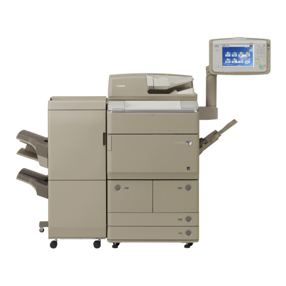
- Page 1 August 10, 2010 Revision 2 imageRUNNER ADVANCE 8105 / 8095 / 8085 Series Service Manual Product Overview Technology Periodic Service Parts Replacement and Clearning Adjustment Troubleshooting Error Code Service Mode Installation Appendix...
- Page 2 This manual is copyrighted with all rights reserved. Under the copyright laws, this manual may changes in the contents of this manual over a long or short period, Canon will issue a new not be copied, reproduced or translated into another language, in whole or in part, without the written consent of Canon Inc.
- Page 3 The following rules apply throughout this Service Manual: Explanation of Symbols The following symbols are used throughout this Service Manual. Each chapter contains sections explaining the purpose of specific functions and the relationship between electrical and mechanical systems with reference to the timing of Symbols Explanation Symbols...
- Page 4 Blank Page...
- Page 5 Specifications ---------------------------------------------------------------- 1-10 Contents Product Specifications -----------------------------------------------------------1-10 Power Supply Specifications: -------------------------------------------------- 1-11 Weight and Size ------------------------------------------------------------------- 1-11 Productivity (Print Speed) -------------------------------------------------------1-12 Safety Precautions Paper Type -------------------------------------------------------------------------1-13 External View/Internal View ---------------------------------------------- 1-24 CDRH Act -----------------------------------------------------------------------0-2 External View ----------------------------------------------------------------------1-24 Laser Safety --------------------------------------------------------------------0-2 Handling of Laser System --------------------------------------------------0-2 External Cover ------------------------------------------------------------------------------1-24 Switches, I/F, Others ----------------------------------------------------------------------1-25...
- Page 6 Controls -----------------------------------------------------------------------------2-12 Controls -----------------------------------------------------------------------------2-53 Flow of Image Data -----------------------------------------------------------------------2-12 Exposure -------------------------------------------------------------------------------------2-54 Security features (encryption key and certificate, password protection) -----2-13 Primary Charging --------------------------------------------------------------------------2-55 High capacity HDD (Option) ------------------------------------------------------------2-22 Developing ----------------------------------------------------------------------------------2-57 HDD mirroring feature (option) ---------------------------------------------------------2-22 Transfer --------------------------------------------------------------------------------------2-59 Removable HDD (option) ----------------------------------------------------------------2-27 Separation -----------------------------------------------------------------------------------2-63 HDD Encryption/ Mirroring Kit (optional) ---------------------------------------------2-28 Drum Cleaning -----------------------------------------------------------------------------2-65...
- Page 7 Servicing -------------------------------------------------------------------------- 2-119 Jam Dection ---------------------------------------------------------------------- 2-153 Jam Code List ---------------------------------------------------------------------------- 2-153 Periodically Replaced Parts ----------------------------------------------------------- 2-119 Consumable Parts ----------------------------------------------------------------------- 2-119 Forced Paper Feed Control ----------------------------------------------------------- 2-155 Periodical Servicing List---------------------------------------------------------------- 2-119 Servicing -------------------------------------------------------------------------- 2-156 When Replacing Parts------------------------------------------------------------------ 2-120 Periodically Replaced Parts ----------------------------------------------------------- 2-156 Troubleshooting -------------------------------------------------------------------------- 2-121 Consumable Parts ----------------------------------------------------------------------- 2-156 Periodical Servicing List---------------------------------------------------------------- 2-156...
- Page 8 Login Service -------------------------------------------------------------------- 2-194 Setting the method to login to SMS ---------------------------------------- 2-176 About Login Service--------------------------------------------------------------------- 2-194 Outline -------------------------------------------------------------------------------------- 2-176 Setting for login by Password Authentication ------------------------------------- 2-176 Default Authentication overview------------------------------------------------------ 2-195 Setting for login by RLS Authentication -------------------------------------------- 2-177 SSO-H (Single Sign-On-H) overview ----------------------------------------------- 2-195 Authentication methods of SSO-H -------------------------------------------------- 2-195 Checking MEAP Application Management Page ----------------------- 2-178...
- Page 9 List of Motor ------------------------------------------------------------------------4-40 Option for exclusive individual measure ---------------------------------- 2-217 List of Sensor ----------------------------------------------------------------------4-46 Display Setting of Copy Icon (level2) ----------------------------------------------- 2-217 List of Switch -----------------------------------------------------------------------4-52 Error at starting up the MEAP application/Setting List of PCB --------------------------------------------------------------------------4-54 to hide JAM screen (level 2) ---------------------------------------------------------- 2-217 Setting of Screen Transition from MEAP Screen Heater,others -----------------------------------------------------------------------4-58 to the Standard Screen (level2) ------------------------------------------------------ 2-218...
- Page 10 Removing the Developing Assembly --------------------------------------- 4-128 Removing the Main Thermistor ---------------------------------------------- 4-186 Cleaning the Developing Assembly ---------------------------------------- 4-131 Removing the Sub Thermistor 1 -------------------------------------------- 4-188 Removing the ETB Unit ------------------------------------------------------- 4-133 Removing the Sub Thermistor 2 -------------------------------------------- 4-189 Removing the Upper Separation Claw ------------------------------------ 4-190 Removing the ETB ------------------------------------------------------------- 4-135 Cleaning the Upper Separation Claw -------------------------------------- 4-190 Cleaning the ETB --------------------------------------------------------------- 4-136...
- Page 11 Removing the Main Drive Unit ----------------------------------------------- 4-225 Troubleshooting External Auxiliary System ----------------------------------------------- 4-230 Test Print ------------------------------------------------------------------------6-2 Removing the Filter (for primary charging) ------------------------------- 4-230 Overview ----------------------------------------------------------------------------- 6-2 Removing the Ozone Filter --------------------------------------------------- 4-230 How to View the Test Print ------------------------------------------------------- 6-3 Removing the DC Controller PCB ------------------------------------------ 4-231 Grid (TYPE=1) ------------------------------------------------------------------------------- 6-3 Removing the Power Supply Assembly ----------------------------------- 4-234...
- Page 12 Version upgrade ------------------------------------------------------------- 6-33 Error Code Overview ----------------------------------------------------------------------------6-33 Overview ------------------------------------------------------------------------7-2 Overview of Version Upgrade ----------------------------------------------------------6-33 Outline -------------------------------------------------------------------------------- 7-2 Writing System Software -----------------------------------------------------------------6-34 Location code -------------------------------------------------------------------------------- 7-2 System Software Components ---------------------------------------------------------6-35 Location code -------------------------------------------------------------------------------- 7-2 Note on Download Process -------------------------------------------------------------6-36 Points to Note When Clearing MN-CON ---------------------------------------------- 7-2 Version Upgrade via SST -------------------------------------------------------6-36 Points to Note When Clearing HDD---------------------------------------------------- 7-2 Overview -------------------------------------------------------------------------------------6-36...
- Page 13 (SORTER>P058 to P059) ---------------------------------------------------------------8-60 Service Mode Staple Finisher - D1 / Booklet Finisher -D1 (SORTER>P001 to P059) ------8-60 Overview ------------------------------------------------------------------------8-2 Inner Trimmer - A1 (SORTER>P024 to P028) -------------------------------------8-75 Service Mode Menu --------------------------------------------------------------- 8-2 ADJUST -----------------------------------------------------------------------------8-77 Service mode item explanations ----------------------------------------------- 8-2 AE ---------------------------------------------------------------------------------------------8-77 I/O information enhancement --------------------------------------------------- 8-3 ADJ-XY ---------------------------------------------------------------------------------------8-77...
- Page 14 OPTION --------------------------------------------------------------------------- 8-130 FEEDER --------------------------------------------------------------------- 8-229 DISPLAY -------------------------------------------------------------------------- 8-229 FNC-SW ----------------------------------------------------------------------------------- 8-130 DSPLY-SW -------------------------------------------------------------------------------- 8-137 ADJUST --------------------------------------------------------------------------- 8-230 IMG-FIX ------------------------------------------------------------------------------------ 8-140 FUNCTION ----------------------------------------------------------------------- 8-231 IMG-DEV ----------------------------------------------------------------------------------- 8-143 OPTION --------------------------------------------------------------------------- 8-233 IMG-LSR ----------------------------------------------------------------------------------- 8-146 SOATER --------------------------------------------------------------------- 8-234 IMG-RDR ---------------------------------------------------------------------------------- 8-146 ADJUST --------------------------------------------------------------------------- 8-234 IMG-MCON -------------------------------------------------------------------------------- 8-148 FUNCTION ----------------------------------------------------------------------- 8-242 CLEANING -------------------------------------------------------------------------------- 8-151...
- Page 15 Other Installation Work ----------------------------------------------------------9-29 Cassette Heater Unit ------------------------------------------------------- 9-54 Setting the Deck -------------------------------------------------------------------9-30 Checking the Contents (Asia only) -------------------------------------------9-54 Setting the Paper Cassette -----------------------------------------------------9-32 Cassette Heater Unit-38 -----------------------------------------------------------------9-54 Auto Adjust Gradation -----------------------------------------------------------9-33 Checking the Parts to be Installed (Europe only) -------------------------9-54 Check Items when Turning OFF the Main Power ------------------------9-54 Image Position Adjustment -----------------------------------------------------9-33 Left Edge Margin Adjustment (1st side) ----------------------------------------------9-33...
- Page 16 Check Items when Turning OFF the Main Power-------------------------9-87 Points to Note Regarding Data Backup/Export-------------------------- 9-122 Installation Procedure ------------------------------------------------------------9-88 Making a Backup of the Data (Reference only) ------------------------- 9-123 Check Items when Turning OFF the Main Power----------------------- 9-127 Removing the Main Controller PCB 1 ------------------------------------------------9-88 Installing the Expansion Bus-F1 and the IPSec Board-B2 Simultaneously -9-89 Installation Procedure ---------------------------------------------------------- 9-127 Installing the Expansion Bus-F1, the Wireless LAN Board-B1 and...
- Page 17 Checking the Contents -------------------------------------------------------- 9-159 [TYPE-7] Option HDD (250GB) + HDD Data Encryption & Option HDD (250GB) ------------------------------------------------------------------- 9-159 Mirroring Kit ----------------------------------------------------------------- 9-197 Points to Note when Unpacking HDD Data Encryption & HDD Mirroring Kit or HDD Data Encryption & Mirroring Kit ------------------- 9-160 Points to Note when HDD Data Encryption &...
- Page 18 Installation Procedure ---------------------------------------------------------- 9-225 Setting for Mirroring ------------------------------------------------------------ 9-266 Removing the HDD and HDD Case Unit ------------------------------------------ 9-225 Reporting to the System Administrator at the End of the Work (Only Disassembling and Assembling of the HDD Removed from When HDD Data Encryption & Mirroring Kit has been Installed) --- 9-266 Execution of Auto Gradation Adjustment---------------------------------- 9-266 the Host Machine (the First HDD) --------------------------------------------------- 9-228 Assembling the Option HDD (the Second HDD) -------------------------------- 9-230...
- Page 19 Installation Procedure ---------------------------------------------------------- 9-298 General Timing Chart ----------------------------------------------------- 10-VI Basic sequence at power ON -------------------------------------------------10-VI Assembling the Option HDD ---------------------------------------------------------- 9-298 Removing the HDD and HDD Case Unit ------------------------------------------ 9-300 Basic sequence at printing Changing Configuration inside of HDD Case Unit ------------------------------ 9-303 <Condition: A4 1-sided (2 sheets), Right deck, Reverse delivery>...
- Page 20 400 to 499 ---------------------------------------------------------------------------- 10-LXXIV General Circuit Diagram (30/30) -----------------------------------------------------10-XL List of User Mode -------------------------------------------------------- 10-XLI 500 to 599 -----------------------------------------------------------------------------10-LXXV Device Information Delivery Settings ------------------------------------- 10-XLI 600 to 699 -----------------------------------------------------------------------------10-LXXV Environment Settings -------------------------------------------------------- 10-XLII 700 to 799 -----------------------------------------------------------------------------10-LXXV 800 to 899 ---------------------------------------------------------------------------- 10-LXXVI Paper Settings -------------------------------------------------------------------------- 10-XLII 900 to 999 --------------------------------------------------------------------------- 10-LXXVII Display Settings ------------------------------------------------------------------------ 10-XLII...
-
Page 21: Safety Precautions
Safety Precautions ■ CDRH Act Laser Safety ■ ■ Handling of Laser System ■ Turn power switch ON ■ Safety of Toner ■ Notes Before it Works Serving ■ Points to Note at Cleaning imageRUNNER ADVANCE 8105 PRO/8095 PRO/8085 PRO Series... - Page 22 Safety Precautions > Handling of Laser System Handling of Laser System CDRH Act When servicing the area around the laser assembly, be sure to turn off the main power. The Center for Devices and Radiological Health of the US Food and Drum Administration put into force regulations concerning laser products on August 2, 1976.
-
Page 23: About Toner
Safety Precautions > Notes Before it Works Serving Turn power switch ON Safety of Toner The machine is equipped with 2 power switches: main power switch and control panel power About Toner switch. The machine goes on when the main power switch is turned on (i.e., other than in low power The machine's toner is a non-toxic material made of plastic, iron, and small amounts of dye. - Page 24 Safety Precautions > Points to Note at Cleaning Points to Note at Cleaning When performing cleaning using organic solvent such as alcohol, be sure to check that the component of solvent is vaporized completely before assembling. Safety Precautions > Points to Note at Cleaning...
-
Page 25: Product Overview
Product Overview ■ Product Lineup ■ Features Specifications ■ ■ External View/Internal View ■ Operation Product Overview... -
Page 26: Main Body
Product Overview > Product Lineup > Pickup/Delivery System Option > Applicable Option for Each Model Product Lineup Pickup/Delivery System Option ■ Applicable Option for Each Model Main Body ● Combination imageRUNNER ADVANCE 8105 / 8095 / 8085 *The underlined numerical value indicates the print speed (ppm: print per minute). F-1-2 F-1-2 *1: Other than CMJ, CCN, TAIWAN... - Page 27 Product Overview > Product Lineup > Pickup/Delivery System Option > Required Options/Conditions Required options, conditions, etc. ■ Product name (Japan) Required Options/Conditions Paper weight: 52 to 256 g/m Booklet Finisher-D1 Maximum stacking capacity: 4250 sheets (A4, B5, LTR) ● Pickup System Options Staple: 100 sheets (A4, B5, LTR) Saddle: 20-sheet saddle stitching Required options, conditions, etc.
- Page 28 Product Overview > Product Lineup > Scanning System Options > Required Options and Conditions Required options, conditions, etc. Scanning System Options Product name Multi Color Image Reverse 2-sided scanning B/W (1-sided/2-sided): 600 dpi=85/40 ipm, 300 dpi: 85/40 ipm ■ Reader Unit-C1 Required Options and Conditions Color (1-sided/2-sided): 600 dpi=51/20 ipm, 300 dpi:85/40 ipm Paper weight:...
-
Page 29: Function Expansion System Options
Product Overview > Product Lineup > Function Expansion System Options > Required Options and Conditions Required options, conditions, etc. Function Expansion System Options Product name (Japan) Product configuration consists of Voice Guidance PCB and Voice Guidance Kit-F1 ■ Voice Guidance Unit. Required Options and Conditions No particular options and conditions are required. - Page 30 Product Overview > Product Lineup > Function Expansion System Options > Required Options and Conditions ● License Products Required options, conditions, etc. Product name (Japan) At the time of installation, obtain the license number according to the license certificate Watermark Expansion Kit-B1 No particular options and conditions are required.
-
Page 31: Service Features
Product Overview > Features > Service Features > Improved Service Operability Features Service Features ■ Improved Service Operability Product Features ● Removing of the Process Unit becomes easy. The Process Unit can be removed by accessing only from the front side. High productivity High image quality Energy saving... - Page 32 Product Overview > Features > Service Features > Improved Upgrading Operability ■ New Service Mode ● Easy access to the parts at rear side. Since the Rear Cover Unit becomes a retractable unit, access to the parts at rear side The description of each service mode item is displayed as well.
- Page 33 Product Overview > Features > Service Features > Applying New Connectors ■ Jam/Error Code Display Specifications ■ Applying New Connectors Newly-configured connectors are used as some connectors on each controller PCB. Jam Code “Jam Code” and “Location Code” are displayed on the screen (*) when a paper jam occurs. aabbbb aa : location bbbb : jam code...
-
Page 34: Product Specifications
Product Overview > Specifications > Product Specifications 1-10 Specifications A4, B5, LTR Paper size Deck A3, B4, A4, A4R, B5, B5R, K8, K16, K16R, LDR, LGL, LTR, Cassette LTRR, STMTR, EXEC, 11” × 17”(279.4 × 431.8 mm), 12” × Product Specifications 18”... -
Page 35: Power Supply Specifications
Product Overview > Specifications > Weight and Size 1-11 Power Supply Specifications: Weight and Size Power Product name Width (mm) Depth (mm) Height (mm) Weight (kg) North imageRUNNER ADVANCE 8105 / 1220 supply Japan Europe Asia Australia America 8095 / 8085 Product name source POD Deck Lite-A1... - Page 36 Product Overview > Specifications > Productivity (Print Speed) 1-12 Productivity (Print Speed) Unit: sheets / minute Feeding Width imageRUNNER ADVANCE 8105 imageRUNNER ADVANCE 8095 imageRUNNER ADVANCE 8085 Paper type Size direction direction Deck / Cassette Multi-purpose Tray Deck / Cassette Multi-purpose Tray Deck / Cassette Multi-purpose Tray...
-
Page 37: Paper Type
Product Overview > Specifications > Paper Type 1-13 Paper Type Following shows the types of usable papers. See the table below for the custom paper size. Type Feeding direction (mm) Width direction (mm) Custom paper size 0-1 148.0 to 487.7 100 to 139.6 Custom paper size 0-2 148.0 to 181.9... - Page 38 Product Overview > Specifications > Paper Type 1-14 Feeding Width Pickup position Multi-purpose POD Deck Type Size direction direction Left Deck Right Deck Cassette3 Cassette4 Paper Deck Insertion Unit Lite (mm) (mm) Tray Thin paper (52 to 63 g/m 11x17 431.8 279.4 355.6...
- Page 39 Product Overview > Specifications > Paper Type 1-15 Feeding Width Pickup position Multi-purpose POD Deck Type Size direction direction Left Deck Right Deck Cassette3 Cassette4 Paper Deck Insertion Unit Lite (mm) (mm) Tray Plain paper 1 (64 to 90 g/m Recycled paper 1 (64 to 90 g/m Color paper...
- Page 40 Product Overview > Specifications > Paper Type 1-16 Feeding Width Pickup position Multi-purpose POD Deck Type Size direction direction Left Deck Right Deck Cassette3 Cassette4 Paper Deck Insertion Unit Lite (mm) (mm) Tray Heavy paper 1 (91 to 180 g/m Letterhead 11x17 431.8...
- Page 41 Product Overview > Specifications > Paper Type 1-17 Feeding Width Pickup position Multi-purpose POD Deck Type Size direction direction Left Deck Right Deck Cassette3 Cassette4 Paper Deck Insertion Unit Lite (mm) (mm) Tray Heavy paper 2 (181 to 220 g/m 11x17 431.8 279.4...
- Page 42 Product Overview > Specifications > Paper Type 1-18 Feeding Width Pickup position Multi-purpose POD Deck Type Size direction direction Left Deck Right Deck Cassette3 Cassette4 Paper Deck Insertion Unit Lite (mm) (mm) Tray Heavy paper 3 (221 to 256 g/m 11x17 431.8 279.4...
- Page 43 Product Overview > Specifications > Paper Type 1-19 Feeding Width Pickup position Multi-purpose POD Deck Type Size direction direction Left Deck Right Deck Cassette3 Cassette4 Paper Deck Insertion Unit Lite (mm) (mm) Tray Transparency 11x17 431.8 279.4 355.6 215.9 215.9 279.4 LTRR 279.4...
- Page 44 Product Overview > Specifications > Paper Type 1-20 Feeding Width Pickup position Multi-purpose POD Deck Type Size direction direction Left Deck Right Deck Cassette3 Cassette4 Paper Deck Insertion Unit Lite (mm) (mm) Tray Labels 11x17 431.8 279.4 355.6 215.9 215.9 279.4 LTRR 279.4...
- Page 45 Product Overview > Specifications > Paper Type 1-21 Feeding Width Pickup position Multi-purpose POD Deck Type Size direction direction Left Deck Right Deck Cassette3 Cassette4 Paper Deck Insertion Unit Lite (mm) (mm) Tray Vellum (Tracing) 11x17 431.8 279.4 355.6 215.9 215.9 279.4 LTRR...
- Page 46 Product Overview > Specifications > Paper Type 1-22 Feeding Width Pickup position Multi-purpose POD Deck Type Size direction direction Left Deck Right Deck Cassette3 Cassette4 Paper Deck Insertion Unit Lite (mm) (mm) Tray Cotton (Bond) 11x17 431.8 279.4 355.6 215.9 215.9 279.4 LTRR...
- Page 47 Product Overview > Specifications > Paper Type 1-23 Feeding Width Pickup position Multi-purpose POD Deck Type Size direction direction Left Deck Right Deck Cassette3 Cassette4 Paper Deck Insertion Unit Lite (mm) (mm) Tray Tab paper 215.9 279.4 Pre-Punched paper 215.9 279.4 Postcard Postcard...
-
Page 48: External View
Product Overview > External View/Internal View > External View > External Cover 1-24 External View/Internal View External View [17] [33] ■ External Cover [32] [31] [30] [18] [29] [16] [28] [19] [27] [15] [26] [20] [25] [24] [21] [23] [14] [22] F-1-14 F-1-14... - Page 49 Product Overview > External View/Internal View > Cross-Section View 1-25 Cross-Section View ■ Switches, I/F, Others Drum Cleaning Unit Pre-exposure Primary Charging Assembly ETB Unit Laser Scanner (Transfer Belt Unit) Unit Multi-purpose Tray Pickup Unit Fixing Assembly Developing Assembly Pre-transfer Reverse Delivery Unit Charging Assembly Main Power Switch...
-
Page 50: Power Switch
Product Overview > Operation > Power Switch > Points to Note on Turning ON/OFF the Power Switch 1-26 Operation Power Switch ■ Types of Power Switches This machine has the Main Power Switch, the Control Panel Power Switch and the Environment Heater Switch. -
Page 51: Main Menu
Product Overview > Operation > Control Panel > Main Menu 1-27 ■ Control Panel Main Menu ■ Control Panel Processing/Date Error Settings/Registration Energy Saver Main Menu Quick Menu Scan and Send Fax / I-Fax Log In/Out Clear Inbox Reset Stop Status Monitor/Cancel Start F-1-17... - Page 52 Product Overview > Operation > Control Panel > Settings/Registration Menu 1-28 ■ ■ Differences in Main Menu Settings/Registration Menu iR 7105/iR 5075 Series iR ADVANCE 8105 / iR ADVANCE 6075 Series Settings/Registration Copy Copy Send/Fax Scan and Send Select an item to set Scan and Save (New) Mail Box Access Stored Files (New)
- Page 53 Product Overview > Operation > Control Panel > Differences in Settings/Registration Menu 1-29 ■ Differences in Settings/Registration Menu iR 7105/7095/7085 Series iR ADVANCE 8105/8095/8085 Series Common Settings Preferences Timer Setting Adjustment/Cleaning Adjustment/Maintenance System Settings Management Settings Output Report Function Settings Copy Settings Send/Receive Settings Mail Box Settings...
- Page 54 Technology ■ Basic Configuration ■ Main Controller Laser Exposure System ■ ■ Image Formation System ■ Fixing ■ Pickup / Feed System ■ External Auxiliary System ■ MEAP ■ Embedded RDS Technology...
-
Page 55: Functional Configuration
Technology > Basic Configuration > Functional Configuration Basic Configuration Functional Configuration The machine may broadly be divided into the following functional system blocks; document exposure system block, controller system block, laser exposure system block, image formation system block, fixing system block and pickup/feed system block. Document exposure system Reader Exposure lamp... - Page 56 Technology > Basic Configuration > Basic Sequence > Basic sequence at power ON Basic Sequence Basic sequence at power ON ■ Start key ON STBY INTR PRINT LSTR STBY Print Unit Print Status PTOP Video Signal Polygon Motor(M44) ETB Motor(M43) Developing Motor(M2) Drum Motor(M1) Developing Clutch(CL1)
- Page 57 Technology > Basic Configuration > Basic Sequence > Basic sequence at printing <Condition: A4 1-sided (2 sheets), Right deck, Reverse delivery> ■ Basic sequence at printing <Condition: A4 1-sided (2 sheets), Right deck, Reverse delivery> Start key ON Print Unit STBY INTR PRINT...
- Page 58 Technology > Basic Configuration > Basic Sequence > Basic sequence at printing <Condition: A4 2-sided (2 sheets), Right deck, Reverse delivery> ■ Basic sequence at printing <Condition: A4 2-sided (2 sheets), Right deck, Reverse delivery> Main power ON INITIAL INITIAL ROTATION STBY Print Unit Polygon Motor(M44)
- Page 59 Technology > Main Controller > Overview > Features Main Controller PCBs 1 and 2 are connected through the Riser (connector for interface). Main Controller Removability/installability of Main Controller PCB 1 has been improved by introducing this configuration (Slot-in/out) Overview ■ Features Using a new controller enables high speed PDL processing, high image quality and high functionality.
- Page 60 Technology > Main Controller > Overview > Specifications/configuration ■ Specifications/configuration ● Memory Main controller PCB 1 ● PCBs J2032 J2031 BAT1 DDR2-SDRAM 512MB+512MB Main Controller PCB 1 Main Controller PCB 2 HDD(Option) HDD(Standard) F-2-8 F-2-8 TPM PCB Function, specifications, features Parts name Flash PCB DDR2-SDRAM 2 slot / 1GB (standard)
- Page 61 Technology > Main Controller > Overview > Specifications/configuration ● I/F, connector Main controller PCB 2 Main controller PCB 1 BAT1 J1003 DDR2-SDRAM J1003 512MB Standard Mini-USB J1007 J1015 DDR2-SDRAM 512MB Option J1017 USB(D) Riser J1018 J1019 USB(H) J1021 Flash J1020 F-2-9 F-2-9 F-2-10...
- Page 62 Technology > Main Controller > Overview > Specifications/configuration ● Main controller PCB 2 Function expansion options Main controller PCB1 Voice Reader Operation/ Data Analyzer Board Voice J1017 Guidance Expansion Bus Memory PCB Riser DC Controller Image Wireless LAN PCB IPSec PCB Power Supply HDD Mirroring Power Supply Control...
- Page 63 Technology > Main Controller > Overview > HDD 2-10 ■ Main controller PCB 2 The partitions for Advanced Box and the distribution server are added. User Box (same as the existing machine) area is 23GB and Advanced Box area is 9GB. Advanced Box area can be increased by installing the high-capacity HDD option.
-
Page 64: Shutdown Sequence
Technology > Main Controller > Overview > Boot/Shutdown sequence 2-11 ■ Boot/Shutdown sequence Related error codes (major error codes): Error code Error description ● Boot sequence E602 HDD error 0001 HDD failed to be recognizedStartup partition (BOOTDEV) is not found at startup No system software for the main CPU 0002 [ ]: program storage location... -
Page 65: Flow Of Image Data
Technology > Main Controller > Controls > Flow of Image Data 2-12 ● Print Controls Flow of Image Data ■ Network Following shows major image data flow. The arrow mark indicates the flow of image data. • ① Numbers (1, 2, etc.) indicate processing order. •... - Page 66 Technology > Main Controller > Controls > Security features (encryption key and certificate, password protection) 2-13 ● ■ Security features (encryption key and certificate, password SEND protection) Reader ● Overview ⑤ ① The main controller PCB 1 of the host machine holds a new PCB named “TPM PCB”. “TPM” Scan type image Format conversion processing...
- Page 67 Technology > Main Controller > Controls > Security features (encryption key and certificate, password protection) 2-14 ● Configuration of Security Information security information is not decodable correctly in case the HDD is failed or formatted because the public key information stored in the HDD is cleared. If this occurs, execute “Initialize All The security functionality behaves differently depending on the TPM setting on the UI.
- Page 68 Technology > Main Controller > Controls > Security features (encryption key and certificate, password protection) 2-15 ● ● Preparation before Installing TPM Works before / after introduction Before installing TPM, ask the user to back up data. Execute the following in Setting / Registration mode (“TPM setting” is OFF by default). Follow the steps below to back up data.
- Page 69 Technology > Main Controller > Controls > Security features (encryption key and certificate, password protection) 2-16 1. Enable Functionality 2.TPM Key Backup The TPM key backup file can be stored only in USB flash drive (supported file system: MEMO: Setup of “System Management PIN” FAT32).
- Page 70 Technology > Main Controller > Controls > Security features (encryption key and certificate, password protection) 2-17 3) Click [Password] to enter the password (4-12 digits). Then, enter the password for CAUTION: The following may cause failures in backup. confirmation. If any of the following is detected, the backup process is aborted and the message and the cause for the failure are shown on the screen.
- Page 71 Technology > Main Controller > Controls > Security features (encryption key and certificate, password protection) 2-18 3. Restore of TPM key CAUTION: The following may cause failures in restoration. Procedure is about the same as the backup work. If any of the following is detected, the restoration process is aborted and the message Difference between restore work and backup work: and the cause for the failure are shown on the screen.
- Page 72 Technology > Main Controller > Controls > Security features (encryption key and certificate, password protection) 2-19 Key pair and server certificate registered in Management Setting (Setting/ Registration) > 4. Disable the feature To set “OFF” for the TPM setting, execute [Initialize All Data / Settings]. [Device Management] >...
- Page 73 Technology > Main Controller > Controls > Security features (encryption key and certificate, password protection) 2-20 ● Overview of Actions taken against Troubles ● Related Error Code Location Error Error description, Assumed cause, remedy TPM Setting = ON TPM Setting = OFF Relevant Error Code with failure Code...
- Page 74 Technology > Main Controller > Controls > Security features (encryption key and certificate, password protection) 2-21 ● Security Information Storage Location Storage Backup Data Type Function Name of Data Location Availability Storage Backup Password/ Network Data Type Function Name of Data SRAM Policy common key for IPSec Location...
- Page 75 Technology > Main Controller > Controls > HDD mirroring feature (option) 2-22 ■ ■ High capacity HDD (Option) HDD mirroring feature (option) The HDD capacity mounted on this machine is 80GB as standard. Mounting a 2.5 inch/ This option enables mirroring of HDD data (RAID1). In the case of failure in one HDD, the operation is performed with the other HDD.
- Page 76 Technology > Main Controller > Controls > HDD mirroring feature (option) 2-23 Mirroring PCB controls reading/writing timing of HDD data. ● To start using this feature (installation) LED PCB makes the LED show operation status of the HDDs. HDD1 is connected to Ch A on the Install HDD2 mirroring PCB HDD2 is connected to Ch B on the...
- Page 77 Technology > Main Controller > Controls > HDD mirroring feature (option) 2-24 “Rebuild” progress is shown in a massage at the status line on the control panel. ● HDD reading/writing operation “Copying hard disk data... xx%“ At reading: At writing: Data is read by HDD1 (master HDD) The same data is written to each HDD at MEMO:...
- Page 78 Technology > Main Controller > Controls > HDD mirroring feature (option) 2-25 ● Mode Flow at Start-up Description of Modes The mirroring system of this machine consists of 4 modes. Turn ON Main Power Switch The modes in parentheses show the mirroring system statuses. The status flows among the modes below during operation.
- Page 79 Technology > Main Controller > Controls > HDD mirroring feature (option) 2-26 Mode Flow during Operation ● Overview of Trouble Recovery When any trouble occurs in the mirroring system, take the action for recovery appropriate to each mode. Mirror Mode The HDD in trouble can be located by the red LED on the LED PCB.
- Page 80 Technology > Main Controller > Controls > Removable HDD (option) 2-27 ● ■ Points to Note in Servicing concerning Mirroring Functionality Removable HDD (option) 1. The modes other than Mirror Mode indicate troubles, which require swift recovery. With this option, users can easily install or remove the HDD (slot-in/out). The power can be turned OFF even during Rebuild process.
- Page 81 HDD encryption and mirroring functionality It is not possible two-way authentication with the dedicated chipset on a board (Canon MFP Security Chip Version 2.00). Since the two functions are operated in a HDD, the encryption functionality can be independently enabled.
- Page 82 Technology > Main Controller > Controls > HDD Encryption/ Mirroring Kit (optional) 2-29 *1: How to Initialize Encryption Board The figure below shows the final screen in initializing the encryption board. The message as shown in the figure below is shown on the screen. 1.
- Page 83 Technology > Main Controller > Controls > HDD Encryption/ Mirroring Kit (optional) 2-30 E610 and detailed codes Detailed E code Cause (Detected Error) Actions Code E610 Failure in the HDD encryption key Ask the user to check the hardware 0001 Failure in the HDD encryption key (Error in hardware configuration).
- Page 84 Technology > Main Controller > Service Operations > HDD 2-31 2. After Replacing Service Operations 1) HDD format ■ 1-1) Start with the safe mode. (While pressing 2 and 8 keys simultaneously, turn ON the main powerswitch.) <Procedure of parts replacement> 1-2) Use SST to format all partitions.
- Page 85 Technology > Main Controller > Service Operations > Main Controller PCB 1 2-32 ■ Main Controller PCB 1 When using the Card Reader and imageWARE Accounting Manager <Procedure of parts replacement> Card ID used for imageWARE Accounting Manager is stored in the HDD, so NSA see “Removing Main Controller PCB 1,”...
- Page 86 Technology > Main Controller > Service Operations > Main Controller PCB 2 2-33 1. Before Replacing MEMO: Perform the following operations. Be sure to get an approval from the user beforehand. Resetting/registering the data is not necessary after Main Controller PCB 1 is replaced. 1) Backup of the set/registered data Use the Remote UI.
- Page 87 Technology > Main Controller > Service Operations > TPM PCB 2-34 3. After Replacing 1) After installing the parts, turn ON the main power switch. 2) Restoring the backup data Use the Remote UI. Management Settings > Data Management > Import/Export 3) Resetting/registering the data While referring to the list of set/registered data which was printed out before replacement, reset/register the data.
- Page 88 Technology > Main Controller > Service Operations > Flash PCB 2-35 ■ Flash PCB <Procedure of parts replacement> see “Removing Main Controller PCB 1,” on p. 4-80. <Procedure of adjustment> Any operation is not necessary at replacement. 2-35 Technology > Main Controller > Service Operations > Flash PCB...
- Page 89 Technology > Laser Exposure System > Overview > Overview 2-36 Laser Exposure System Laser is applied to the Nom-image image on the positively-charged drum with this machine. Overview Image area Non-image area Non-image area ■ Overview This machine uses an 8-beam method that enables exposure of 8 beams per scanning direction for high productivity.
- Page 90 Technology > Laser Exposure System > Overview > Parts Configuration 2-37 ■ Specifications ■ Parts Configuration Item Description Image Formation Lens Wave length 670nm (large) Laser type Image Formation Lens Red color laser Laser team (small) Laser output 7mW(Max) Number of laser beams 8 beams Reflection mirror Laser Driver PCB...
- Page 91 Technology > Laser Exposure System > Controls > Laser ON Timing Control 2-38 ■ Laser ON Timing Control Controls ● Laser ON/OFF Control Overview ■ This control is performed to turn ON/OFF a laser beam according to the combination of laser control signals.
- Page 92 Technology > Laser Exposure System > Controls > Laser ON Timing Control 2-39 ● Main Scanning Synchronization Control MEMO: This control is performed to adjust the writing position in the main scanning direction. EEPROM on the Laser Driver PCB stores the 8-beam phase displacement coefficient (laser phase coefficient), which is unique to the Laser Scanner Unit, and corrects 8-beam phase difference based on the stored coefficient.
- Page 93 Technology > Laser Exposure System > Controls > Laser Beam Intensity Control 2-40 ● ■ Laser Beam Intensity Control Sub Scanning Synchronization Control This control is performed to adjust the writing position in the sub scanning direction. ● APC (Auto Power Control) Control To keep constant laser light intensity per 8 beams (1BD basis) <Execution timing>...
- Page 94 Technology > Laser Exposure System > Controls > Duplex print magnification correction 2-41 ■ Duplex print magnification correction <Laser Lighting> When the paper passes through the fixing area after the image was created on the 1st side of the 2-sided print, the paper temporarily gets shrunk due to the heat. Then, creating the image Horizontal scanning on the 2nd side causes the 2nd side image extended, which makes the 2nd side image larger than the 1st side image when the paper size returns to the original size after the paper is...
- Page 95 Technology > Laser Exposure System > Controls > Polygon Motor Control 2-42 When magnification is corrected, changing the Polygon Motor speed between sheets might ■ Polygon Motor Control be slower depending on the speed, so productivity might be reduced. This control is performed to rotate the polygon mirror at a specified speed. Variable Reproduction = Polygon Speed Reshuffling <Execution timing>...
-
Page 96: Laser Shutter Control
Technology > Laser Exposure System > Controls > Laser Shutter Control 2-43 ■ Laser Shutter Control To prevent laser exposure in the machine when the Cover is open <Execution timing> When the Front Door or Multi tray Cover opens/closes <Control description> When the Front Door or Multi tray Cover opens, the DC Controller PCB stops power supply (DC5V) of the Laser Driver to prevent laser exposure. - Page 97 Technology > Laser Exposure System > Servicing > Major Adjustments 2-44 Servicing ■ Periodically Replaced Parts None ■ Consumable Parts None Periodical Servicing List ■ Cleaning Parts name Remarks interval Clean when black lines or the like occurs due to soil on Dust-proof glass the Dustproof Glass.
- Page 98 Technology > Image Formation System > Overview > Overview 2-45 Primary Charging Assembly Image Formation System Drum Cleaning Unit Laser Developing Assembly Overview ■ Overview Toner image is formed by the magnetic, 1-component toner projection developing method in image formation system. Photosensitive Drum To ensure high quality print, this machine introduces the following new technologies: •...
- Page 99 Technology > Image Formation System > Overview > Specifications 2-46 ■ Specifications ● Charging Specifications ● Basic Specifications Developing High Primary Charging Pre-transfer Voltage PCB High Voltage PCB Charging PCB Item Function/Method (PCB12) (PCB26) (PCB11) Photosensitive Drum Material A-Si Drum diameter 84 mm diameter Cleaning Cleaning Blade...
- Page 100 Technology > Image Formation System > Overview > Parts Configuration 2-47 ■ Parts Configuration ● Process Area ● Entire Configuration Primary Charging Pre-exposure LED Assembly Grid Wire Toner Container Toner Supply Assembly Drum Cleaning Blade Primary Potential Sensor Charging Wire Developing Blade Drum Cleaning Unit...
- Page 101 Technology > Image Formation System > Overview > Parts Configuration 2-48 ● ● Transfer Area Toner Supply Area Idler Roller Front View Toner Container Hopper Drive Roller Transfer Roller Static Eliminator Cleaning Blade Separation Guide Brush Roller Transfer Belt Cleaning Shaft Engagement Arm Engagement Cam Sub Hopper...
- Page 102 Technology > Image Formation System > Overview > Drive Configuration 2-49 ● ■ Drive Configuration Waste Toner Feeding Area ● Process Area Waste Toner Feed Screw Waste Toner Feed Screw Drum Cleaning Unit ETB cleaning Unit Waste Toner Feed Assembly PS61 PS90 Waste Toner...
- Page 103 Technology > Image Formation System > Overview > Drive Configuration 2-50 ● ● Transfer Area Toner Supply Area PS54 PS55 PS56 F-2-69 F-2-69 Code Parts name Function To make the ETB Unit (ETB) engaged/disengaged Duplex Feed Left Motor ETB Motor To drive the ETB Drive Roller, the Brush Roller and the Waste Toner Feed Screw.
- Page 104 Technology > Image Formation System > Overview > Drive Configuration 2-51 ● Waste Toner Feeding Area Code Parts name Function Buffer Toner Sensor 1 To detect toner level in the Buffer(To avoid oversupply to the Buffer) Buffer Toner Sensor 2 To detect toner level in the Buffer (to detect absence of toner in the Buffer) PS54 Toner Replacement Cover Sensor To detect whether the Toner Replacement Cover is...
-
Page 105: Print Process
Technology > Image Formation System > Overview > Print Process 2-52 ■ Print Process 1.Electrostatic latent image formation Block 2.Primary Charging Block Step Overview Static formation Exposure Light emission from the Pre-exposure LED removes residual block potential on the surface of the Photosensitive Drum to prevent 1.Pre-exposure 3.Laser exposure density unevenness. - Page 106 Technology > Image Formation System > Controls 2-53 Controls Control name Description Exposure Pre-exposure control To apply the light of the Pre-exposure LED on the surface of the Primary Charging Photosensitive Drum. Exposure -Primary charging bias control -Pre-exposure control -Primary charging wire cleaning control Primary charging -Primary charging shutter control Primary charging wire bias...
- Page 107 Technology > Image Formation System > Controls > Exposure 2-54 ■ Exposure Control name Description Toner supply ● To detect toner level in the Developing Unit and the Buffer Unit. Pre-exposure Control Toner level detection Toner supply control To supply toner from the Toner Container to the Developing To prevent uneven density with the print image, residual potential on the Photosensitive Drum Assembly.
- Page 108 Technology > Image Formation System > Controls > Primary Charging 2-55 ■ ● Primary Charging Wire Cleaning Control Primary Charging To prevent charging failure caused by soil of the Primary Charging Wire. ● Primary Charging Bias Control <Execution timing> To make the surface of the Photosensitive Drum evenly and positively charged. •...
- Page 109 Technology > Image Formation System > Controls > Primary Charging 2-56 ● Primary Charging Shutter Control Shutter Open/Close Operation Sequence To prevent uneven potential on the Photosensitive Drum caused by discharge products Elapsing time Operation (nitrogen oxide) accumulated on the Primary Charging Assembly. 1.
- Page 110 Technology > Image Formation System > Controls > Developing 2-57 ■ <Control description> Developing The shutter is open or closed by the cleaning mechanism of the Primary Charging Wire. ● Developing Bias Control The Primary Charging Shutter is made of fiber and usually taken up by the bobbin. To form a toner image on the Photosensitive Drum by charging toner on the Developing The drive of the Primary Charging Wire Cleaning Motor (M6) moves the Cleaning Pad to the Cylinder.
- Page 111 Technology > Image Formation System > Controls > Developing 2-58 ● ● Dust-collection Bias Bontrol Developing Supply Shutter Opening/Closing Mechanism To collect toner which floats over the Photosensitive Drum during developing process. There are shutters at the Supply Mouths of the Developing Assembly and the Buffer Unit to prevent toner scattering.
- Page 112 Technology > Image Formation System > Controls > Transfer 2-59 ■ <Opening and Closing Operations of the Buffer Shutter> Transfer By pushing the Developing Assembly in the main body, edge of the Supply Mouth on the ● Pre-transfer Charging Bias Control assembly hits to leading edge of the Buffer Shutter.
- Page 113 Technology > Image Formation System > Controls > Transfer 2-60 ● ● Pre-transfer Charging Wire Cleaning Control Pre-transfer Charging Shutter Control To prevent charging failure caused by soil of the Pre-transfer Charging Wire. To prevent uneven potential on the Photosensitive Drum caused by discharge products (nitrogen oxide) accumulated on the Pre-transfer Charging Assembly.
- Page 114 Technology > Image Formation System > Controls > Transfer 2-61 ● Transfer Bias Control To transfer toner on the Photosensitive Drum to a paper. Screw The transfer bias (DC positive), which has been generated on the Transfer High Voltage PCB (PCB13), is applied to the Transfer Roller.
- Page 115 Technology > Image Formation System > Controls > Transfer 2-62 ● ● ETB Cleaning Control ETB Engagement/Disengagement Control To prevent image failure caused by toner soil on the ETB, the residual toner on the Transfer To prevent image failure caused by toner soil on the ETB, the ETB is engaged or disengaged Belt is removed.
- Page 116 Technology > Image Formation System > Controls > Separation 2-63 ■ Separation ● Transfer Belt Separation Control Disengagement <Separation from the Drum> Separation is performed using the curvature separation method. Engagement Engagement Arm Flag Transfer Belt Engage Sensor(PS55) Engagement Arm Engagement Cam Paper F-2-88...
- Page 117 Technology > Image Formation System > Controls > Separation 2-64 <Separation from the ETB> Separation is performed using the curvature separation method and the Static Eliminator. There is no bias for separation. Photosensitive Drum Static Eliminator Transfer Belt Separation Guide Separation Claw Paper Paper...
-
Page 118: Drum Cleaning
Technology > Image Formation System > Controls > Drum Cleaning 2-65 ● ■ Separation Claw Reciprocation Control Drum Cleaning By moving the Separation Claw back and forth (reciprocation), scar on the drum caused by ● Drum Cleaning Control the Separation Claw can be prevented. The blade, which is in contact with the Drum, removes residual toner and paper dust on the Photosensitive Drum. - Page 119 Technology > Image Formation System > Controls > Drum-related Issues 2-66 ● ■ Separation Bias Control Drum-related Issues To prevent image soil caused by toner accumulated on the Drum Separation Claw, this ● Drum HP Detection control prevents attachment of toner on the Photosensitive Drum with the Drum Separation To detect home position of the Photosensitive Drum.
- Page 120 Technology > Image Formation System > Controls > Drum Heater Control 2-67 ■ Drum Heater Control To make potential characteristic for charging or exposure stable by keeping the specified temperature of the Photosensitive Drum. The Drum Heater is the flat heater located inside the Photosensitive Drum to keep moisture content on the surface of the Photosensitive Drum constant by turning ON the heater.
- Page 121 Technology > Image Formation System > Controls > Drum Heater Control 2-68 <Operating condition> Operating condition of the heater differs according to the status of the Environment Switch and the host machine. A.2-dimensional shading OFF(defolt*1) <Environment Switch: OFF> Main Power sleep mode (low energy sleep mode (high energy WarmUp(Recovery)
- Page 122 Technology > Image Formation System > Controls > Drum Heater Control 2-69 B.2-dimensional shading ON *1] <Environment Switch: OFF> Main Power sleep mode (low energy sleep mode (high energy WarmUp(Recovery) Mode Standby/Energy Saver Copy/Print consumption)*3 consumption)*3 Main SW Switch Cassette SW Drum Heater Cassette...
- Page 123 Technology > Image Formation System > Controls > Toner Supply Area 2-70 ■ <Environment Control> Toner Supply Area Environment control 1: The condition of the heater at the time of turning OFF the main ● Toner Container Detection power continues. Toner Container detection is not performed with this machine.
- Page 124 Technology > Image Formation System > Controls > Toner Supply Area 2-71 ● Toner Level Detection: MEMO The Toner Excess Supply Sensor (TS2) detects amount of toner around the Buffer Inlet. If toner is supplied excessively from the Sub Hopper to the Buffer Unit (if Toner Container there are toner clusters), toner in the Buffer may overflow.
- Page 125 Technology > Image Formation System > Controls > Waste Toner Feeding Area 2-72 ■ Waste Toner Feeding Area Toner level Status Message Operation 5% or less Replace the toner After "Replace the toner cartridge." ● Waste Toner Full Level Detection cartridge.
- Page 126 Technology > Image Formation System > Controls > Waste Toner Feeding Area 2-73 ● This machine performs the following controls. Waste Toner Feed Screw Lock Detection 1. “Black band control” in order to maintain the drum cleaning performance To detect lock state of the Waste Toner Feed Screw. 2.
-
Page 127: Image Stabilization Control
Technology > Image Formation System > Controls > Image Stabilization Control 2-74 ■ Image Stabilization Control ● Overview This control prevents image failure due to change of the environment or deterioration of the Photosensitive Drum to ensure stabilized print. Primary Laser Power(Lp) Charging Primary current (Ip) - Page 128 Technology > Image Formation System > Controls > Image Stabilization Control 2-75 ● Execution Timing Execution items for image stabilization control differ according to the environment and condition of image formation parts. Following shows the control items at each sequence. Illustration.*70 deg C or lower in the fixing temperature,**60 sec.70 deg C or lower in the fixing temperature,***Fixing temperature remaining high at power OFF/ON Timing Initial...
- Page 129 Technology > Image Formation System > Controls > Image Stabilization Control 2-76 Timing Initial Paper Last Standard Warm-up rotation Interruption Arbitrary rotation interval rotation duration Forcible Control Remarks power PASCAL PASCAL (second) Normal Door interruption Low duty OFF/ Normal (Full (Quick Approx.
- Page 130 Technology > Image Formation System > Controls > Image Stabilization Control 2-77 ● Potential Control <Control description> 1. VD control Perform the following controls according to the deterioration level of the Photosensitive Drum 1) The primary current (Ip_Target_Pre), which has been determined in the last potential and the environmental change.
- Page 131 Technology > Image Formation System > Controls > Image Stabilization Control 2-78 2. VL control [When the drum surface potential is not as follows: -10V <= target potential <= +10V ] • 1) The laser power (LP_Target_Pre), which has been determined in the last bright area When the drum surface potential is as follows: -10V >...
- Page 132 Technology > Image Formation System > Controls > Image Stabilization Control 2-79 Lp is actually calculated by the laser power (LP) and the bright area potential characteristics 3. Determination of developing bias (Vdc) that were obtained in the last VL control because executing VL control each time takes time. Developing bias is determined by adding the Vback value (based on the environment table) When the bright area potential measured value fails to be within the range of the target to VL (bright area potential) determined in the foregoing control.
- Page 133 Technology > Image Formation System > Controls > Image Stabilization Control 2-80 ● Patch Detection <Patch image at D-max control> Toner density is detected by detection of the patch created on the Drum with the Patch Drum rotation direction Sensor. Parts configuration The Patch Sensor consists of the light-emitting part (LED) and the light-receiving part.
- Page 134 Technology > Image Formation System > Controls > Image Stabilization Control 2-81 ● D-max Control 3) Determination of contrast potential (Vcont) Patch image density is read by the Patch Sensor to determine the contrast potential (Vcont) This control determines developing contrast to keep a constant solid image density. (that becomes the target density) using the obtained density characteristics.
- Page 135 Technology > Image Formation System > Controls > Image Stabilization Control 2-82 ● ● D-half Control PASCAL Control This control determines gradation correction value based on the image density detected by This control stabilizes gradation density characteristics on the image. the Patch Sensor This control is executed when the following is selected in user mode: Auto Adjust Gradation >...
- Page 136 Technology > Image Formation System > Controls > Auxiliary Control 2-83 ■ Auxiliary Control Potential changes depending on laser emission ● Startup Contrast Potential (Vcont) Correction Contrast potential (Vcont) is corrected to keep a constant density and prevent light image Vd : Dark area potential caused by reduced toner charging amount in an energy-saving environment.
- Page 137 Technology > Image Formation System > Controls > Auxiliary Control 2-84 ● Laser APC Control Bright area potential This control corrects laser output control value to prevent change of surface potential by laser characteristics( ) output. VL (V) Correction type VL0re Procedure 3) A.
- Page 138 Technology > Image Formation System > Controls > Auxiliary Control 2-85 ● Two Dimension Shading Control DC Controller PCB Uneven potential on the Photosensitive Drum is corrected by laser exposure. Execution timing At the time of laser exposure (only when the two dimension shading control is ON. Default: Calculation OFF) Drum potential...
- Page 139 Technology > Image Formation System > Controls > Auxiliary Control 2-86 ● ● White Band Control Black Band Control This control maintains the cleaning performance by providing sufficient amount of toner to the Oppositely-charged toner on the Developing Sleeve is forcibly applied on the Drum and collected by the Cleaning Unit.
- Page 140 Technology > Image Formation System > Controls > Auxiliary Control 2-87 ● Control description Low Duty Discharge Control 1) Black band described below is created on the Drum. In the case of continuous output of low duty image, this control consumes toner at non-image 2) Black band is scraped by the Drum Cleaning Blade and toner is properly applied on the area to maintain the density stability.
- Page 141 Technology > Image Formation System > Servicing > Periodical Servicing List 2-88 ■ Servicing Periodical Servicing List Expected ■ Periodically Replaced Parts Parts/Area Name Remarks life* COUNTER Toner Receptacle Tray As needed Remove toner on the tray. Expected Parts Name Parts Nunber Piece Remarks Primary Charging Assembly Grid...
- Page 142 Technology > Image Formation System > Servicing > When Replacing Parts 2-89 ■ When Replacing Parts Note: When replacing the Periodically Replaced Parts and Consumable Parts, be sure to clear the Be sure to adjust the dark side (density of the test print image) to be the light side. Parts Counter (COPIER >...
- Page 143 Technology > Image Formation System > Servicing > When Replacing Parts 2-90 Make the resin screws [A] and [C] a full turn clockwise. While referring to the When the rear side test print image is dark replacement procedure of the Primary Charging Assembly, install it to the main body, output MEMO: a test print and check the image.
- Page 144 Technology > Image Formation System > Servicing > When Replacing Parts 2-91 ● Pre-transfer Charging Assembly Note: <Procedure of parts replacement> Since uneven density might occur, be sure to adjust by turning the 2 adjustment see “Removing the Pre-transfer Charging Assembly,” on p. 4-106. screws with the same amount.
- Page 145 Technology > Image Formation System > Servicing > When Replacing Parts 2-92 ● 3) Affix the ID Label included in the drum to the inside of the Front Cover. Drum <Procedure of parts replacement> see “Removing the Photosensitive Drum,” on p. 4-122. <Procedure of adjustment>...
- Page 146 Technology > Image Formation System > Servicing > Major Adjustments 2-93 ● ● Drum Side Seals(Front and Rear) <Procedure of parts replacement> <Procedure of parts replacement> see “Removing the ETB Unit,” on p. 4-133. • see “Removing the Side Seal,” on p. 4-127. <Procedure of adjustment>...
- Page 147 Technology > Image Formation System > Servicing > Troubleshooting 2-94 ■ [Image Sample] Troubleshooting ● Feed direction Trailing Edge Shock Imaget <Shock image located approx. 63mm [Location] 55mm from the trailing edge> .ETB [Cause] Lines occur on the image due to shock when distortion on the belt is released while rotation speed between the ETB and drum differs [Condition] When replacing the ETB...
- Page 148 Technology > Image Formation System > Servicing > Troubleshooting 2-95 ● Uneven density correction by 2D shading 3) Output a halftone image with the following conditions and check if uneven density occurs. COPIER>TEST>PG>TYPE 6 To correct uneven image density caused by uneven potential on the surface of the Drum. Select the cassette which the following paper is set: COPIER>TEST>PG>PG-PICK A3 (LDR) or larger.
- Page 149 Technology > Image Formation System > Servicing > Troubleshooting 2-96 MEMO: MEMO: It is difficult to judge whether uneven potential of the Photosensitive Drum causes For the test print, the following 3 types can be output, but basically set SHD-P1 to uneven density of the output image, so output 3 sheets of the test print and adjust the output.
- Page 150 Technology > Image Formation System > Servicing > Troubleshooting 2-97 As the value is larger, the density becomes lighter. As the value is smaller, the density 5-4) Adjust the target vertical scanning direction (1 to 27) which uneven density is seen. becomes darker.
- Page 151 Technology > Image Formation System > Servicing > Troubleshooting 2-98 ● Separation Failure Jam due to Deformation of Separation Claw [Location] Drum Separation Claw [Cause] When the paper enters to the drum at separation failure, the Separation Claw may be deformed.
- Page 152 Technology > Image Formation System > Servicing > Troubleshooting 2-99 ● Uneven density [Cause] Uneven density occurs on the image because of uneven developing performance or change Feed Direction in drum characteristics due to wear. F-2-127 F-2-127 In the case of dark/light image at either the left or right side on the image in horizontal [Field Remedy] direction, adjust height of the Primary Charging Wire and check the output result.
- Page 153 Technology > Image Formation System > Servicing > Troubleshooting 2-100 ● White line (foreign matter between Developing Sleeves) [Field Remedy] 1) Remove the Developing Assembly. Sample image MEMO: Feed Direction Be sure to place paper on a clean place and take out the foot of the Developing <...
- Page 154 Technology > Image Formation System > Servicing > Troubleshooting 2-101 2) Remove foreign matter caught between the sleeves. 3) Clean excess toner on the upper and lower sleeves. Insert a corner of the paper between the sleeves and scrape out and remove foreign matter Toner can be excessively attached because the toner is pushed to the sleeve when from the side.
- Page 155 Technology > Image Formation System > Servicing > Troubleshooting 2-102 ● 3-3) Check if the toner blown by the blower is attached to the Developing Roller; if the Smeared image toner is attached, wipe it with lint-free paper. [Cause] (Otherwise, the toner is fused to the Roller that causes banding) Excess toner is transferred on the paper that causes toner collapse at the time of fixing, which can generate smeared image on the image.
- Page 156 Technology > Image Formation System > Servicing > Troubleshooting 2-103 [Image] Feed Direction < Smeared Image > Side Line F-2-134 F-2-134 Select the following to execute Full Adjust: “Settings/Registration > Adjustment Maintenance > Adjust Image > Auto Adjust Gradation < Full Adjust”; and check the output result. COPIER >...
- Page 157 Technology > Fixing > Overview > Characteristics 2-104 Flux Fixing High-frequency Magnetic material current (Ferrite Core) Overview Coil ■ Characteristics Metal 1) Whole-circumference IH heating method This machine uses the IH heating method to heat the whole circumference of the Fixing Exothermic Roller.
- Page 158 Technology > Fixing > Overview > Specifications 2-105 ■ Specifications 3) Making the Fixing Assembly as a unit Maintenance performance has been improved by separating the Fixing Unit from the Host Item Function/method Machine to be assigned as a unit. Whole-circumference IH fixing method Fixing method Fixing Heater...
- Page 159 Technology > Fixing > Overview > Parts configuration 2-106 ■ Parts configuration Parts name Function/method Fixing Roller Static Eliminator To prevent leak, static offset and noise ● Cross-section view Pressure Roller Static Eliminator T-2-50 T-2-50 Fixing Cleaning Web takeup roller Fixing Cleaning Web Fixing Cleaning Web feed roller...
- Page 160 Technology > Fixing > Overview > Drive configuration 2-107 ● ■ Drive configuration Thermistor, Thermal Switch Fixing Sub Thermistor 2 Fixing Cleaning Web (THM4) Level Sensor(PS45) Fixing Roller Fixing Cleaning Thermal Switch2 Web Drive Solenoid (TP2) (SL9) Fixing Sub Thermistor 1 Fixing Motor (THM2) (M3)
-
Page 161: Fixing Temperature Control
Technology > Fixing > Controls > Fixing temperature control 2-108 ■ Controls Fixing temperature control ● ■ Overview Overview To prevent fixing failure, temperature control of the Fixing Roller is executed with the following timing. Cleaning Web length detection Temperature control Overview Cleaning Web Temperature control during... - Page 162 Technology > Fixing > Controls > Fixing temperature control 2-109 ● Temperature control during startup <Low temperature environment startup mode> After it reaches the target temperature, the target temperature is maintained until Temperature is controlled to reach the standby temperature. completion of the potential control, and then the machine enters ready state.
- Page 163 Technology > Fixing > Controls > Fixing temperature control 2-110 ● ● Temperature Control for Standby Temperature control during printing The target temperature is reduced step by step on a specified time basis until it reaches a To provide measures against temperature rise of the coil/Main Body and save energy consumption, the target temperature is reduced step by step on a specified time basis until it certain temperature.
- Page 164 Technology > Fixing > Controls > Fixing temperature control 2-111 ● • Low temperature environment Lower than 20 deg C Other temperature adjustments Time (minute) <Energy Saver mode> Destination Paper Type 20 and By pressing the energy saver key on the Control Panel, energy consumption is reduced by 0 to 5 5 to 10 10 to 20...
- Page 165 Technology > Fixing > Controls > Down sequence control 2-112 ● ■ Related Error Code Down sequence control E000: Fixing Assembly low temperature error ● Overview E001: Fixing Assembly high temperature error In the case of great difference between the target temperature and the detected temperature E002: Fixing Assembly temperature rise error at the start of printing or during printing, productivity is dropped to prevent fixing failure or E003: Fixing Assembly temperature decrease error...
- Page 166 Technology > Fixing > Controls > Down sequence control 2-113 ● Control description 2) When printing is started and the paper type is switched Because fixing temperature differs according to the paper type, switching the paper type This control has the 3 types of down sequences according to the execution timing. causes downtime.
- Page 167 Technology > Fixing > Controls > Paper Anti-wrapping Control 2-114 ● ■ Related Service Mode Paper Anti-wrapping Control • To change temperature threshold of down sequence with special paper ● Overview COPIER> OPTION> IMG-FX> FIX-TEMP With this control, failure of the Fixing Assembly caused by paper wrapping around the Fixing 0 : Fixing priority, 1: Normal, 2: Productivity priority Roller and the Pressure Roller is prevented.
- Page 168 Technology > Fixing > Controls > Thermistor reciprocating control 2-115 ● ■ Control description Thermistor reciprocating control In the case of delay jam at the fixing outlet, the DC Controller determines paper wrapping if To prevent scar on the Fixing Roller by the Fixing Main Thermistor (THM01), the Fixing Main the paper remains in the Fixing Assembly and executes the following.
- Page 169 Technology > Fixing > Controls > Cleaning web drive control 2-116 ■ Upper separation claw reciprocating control ■ Cleaning web drive control To prevent scar on the Fixing Roller by the Upper Separation Claw, the Upper Separation To prevent fixing offset, the residual toner on the surface of the Fixing Roller is removed with Claw is moved back and forth by 3mm in the direction of the Fixing Roller.
- Page 170 Technology > Fixing > Controls > Cleaning web length detection 2-117 ● ■ Related Error Code Cleaning web length detection Error in connection of the Fixing Web Solenoid When the length of the Cleaning Web is reduced, the Web Level Detection Arm is moved in 005-0001 the direction of the arrow to block the light path of the Fixing Cleaning Web Level Detection Sensor (PS45).
-
Page 171: Protective Function
Technology > Fixing > Controls > Protective function 2-118 ■ Protective function ● Detecting an Error Using the Thermistor In the event of the following, the machine will set the DC power (12 V) used to drive the AC relay (found on the fixing heater power supply PCB), thereby stopping the AC power to the fixing heater. - Page 172 Technology > Fixing > Servicing > Periodical Servicing List 2-119 ■ Servicing Periodical Servicing List Operation ■ Periodically Replaced Parts Parts/Area Name Piece Remarks Interval Fixing inlet guide Clean with lint-free paper moistened with alcohol. Parts name Parts Number Piece Expected life Remarks Main Thermistor Unit Fixing Right Stay...
- Page 173 Technology > Fixing > Servicing > When Replacing Parts 2-120 ■ When Replacing Parts ● Fixing Roller <Procedure of parts replacement> see “Removing the Fixing Roller, Insulating Bush and Thrust Stopper,” on p. 4-182. <Procedure of adjustment> 1) Grease Application Apply approx.
- Page 174 Technology > Fixing > Servicing > Troubleshooting 2-121 ■ ● Checking nip width Troubleshooting In the case of paper wrinkle or fixing failure, check that the fixing nip width is within the ● Paper wrinkle specified range. Note that the fixing nip width of this equipment cannot be adjusted in the <Location>...
- Page 175 Technology > Fixing > Servicing > Troubleshooting 2-122 ● Image failure due to the temperature rising at the edge of the Fixing <Location of Trouble> Roller (crepe mark) Fixing Roller, Pressure Roller <Cause> This is the symptom which image error like crepe mark occurs when temperature at the edge of the Fixing Roller rises.
- Page 176 Technology > Pickup / Feed System > Overview > Overview 2-123 Pickup / Feed System :Scanner Sensor PS67 PS67 PS29 PS64 :Forced Paper Feed Control Overview :Paper path :One Unit ■ Overview • Improved productivity (75ppm -> 105ppm) PS65 PS28 This feature is enabled by using highly-sensitive Scanner Sensor.
- Page 177 Technology > Pickup / Feed System > Overview > Specifications 2-124 ■ Specifications Item Function/Method Paper Storage Front Loading Method Method Pickup Method Separation Retard Method Paper Feed Center Standard Paper Loading Left/Right Deck 1500 sheets (80 g/m2) Capacity Cassette 3/4 550 sheets (80 g/m2) Multi-purpose 100 sheets (80 g/m2)
- Page 178 Technology > Pickup / Feed System > Overview > Parts configuration 2-125 ■ Parts configuration PS No. Sensor No. Vertical Path Cover Open/Close Sensor ● Switch/Sensor 1 Multi-purpose Cover Open/Close Sensor Fixing Toenail Jam Sensor PS52 PS51 PS10 PS20 PS67 PS47 PS29 PS64...
- Page 179 Technology > Pickup / Feed System > Overview > Parts configuration 2-126 ● Roller Fixing Roller Duplex Merging Roller Multi-purpose Tray Feed Roller Registration Roller Outer Delivery Roller Reverse Inlet Roller Multi-purpose Tray Pickup Roller Inner Delivery Roller Multi-purpose Tray Separation Roller Pressure roller Reverse Upper Roller Registration Front Roller...
- Page 180 Technology > Pickup / Feed System > Overview > Drive Configuration 2-127 ■ Drive Configuration Name Fixing Motor Right Deck Lifter Motor Left Deck Lifter Motor Right Deck Pickup Motor Cassette3/4 Pickup Motor Delivery Motor Reverse Motor Duplex Feed Right Motor Duplex Feed Left Motor Cassette3 Lifter Motor SL12...
-
Page 181: Paper Path
Technology > Pickup / Feed System > Overview > Paper path 2-128 ■ Paper path Feeding path Delivery Flapper Multi Tray Reverse Flapper Duplex Flapper [3],[4] Option Pickup Left Deck Pigkup Right Deck Pigkup Cassette 3 Pickup Cassette 4 Pickup F-2-158 F-2-158 1-side face-up delivery, duplex face-down delivery... - Page 182 Technology > Pickup / Feed System > Overview > Interval speed 2-129 ■ Interval speed ImageRUNNER ADVANCE Model 8105/8095/8085 [mm/s] :Pickup Speed [ppm] :Vertical path/duplex speed Pickup speed :Pre-registration speed Vertical path/duplex speed Pre-registration speed :Post-registration speed Post-registration speed :Process speed Process speed :Delivery speed Delivery speed...
- Page 183 Technology > Pickup / Feed System > Overview > Various types of control 2-130 ■ Various types of control Unit Contorol Basic Movement Fixing Assembly Secondary Transfer Unit Registration Unit Deck/Cassette detection Paper Size Detection Deck/cassette pickup unit Paper Level Detection Paper Detection Pickup Retry Control Pickup Retry Control...
- Page 184 Technology > Pickup / Feed System > Deck/Cassette Pickup Unit > Basic Movement 2-131 ● Cassette Deck/Cassette Pickup Unit Cassette Feed ■ Basic Movement Roller Cassette Pickup PS21 When Deck/Cassette is installed, Motor drives to maintain the height which paper surface Roller /PS22 attaches to Pickup Roller (This is the height of Pickup Roller when Pickup Solenoid is OFF).
- Page 185 Technology > Pickup / Feed System > Deck/Cassette Pickup Unit > Deck/Cassette detection 2-132 ■ ● Cassette Deck/Cassette detection Cassette is detected by Paper Size Detection Switch. When all actuators of the Paper Size Whether Deck/Cassette is installed is detected Detection Switch (SW14/SW16) are not pressed, it is detected as no cassette installed ●...
- Page 186 Technology > Pickup / Feed System > Deck/Cassette Pickup Unit > Paper Size Detection 2-133 ■ ● Cassette aper Size Detection Paper size in cassette 3/4 is each detected by 2 paper size detection switches. ● Deck ON/OFF of 4-actuator in the Host Machine changes according to the Paper Size Detection Circular Plate/ Set in Service Mode.
- Page 187 Technology > Pickup / Feed System > Deck/Cassette Pickup Unit > Paper Size Detection 2-134 ● Paper size detection Switch SW7/SW8 Paper Width Length Width SW7/SW8 Length SW9/SW10 Size (mm) (mm) 257.0 182.0 EXEC 267.0 184.0 270.0 195.0 A5-R 148.5 210.0 297.0 210.0...
- Page 188 Technology > Pickup / Feed System > Deck/Cassette Pickup Unit > Paper Level Detection 2-135 ■ Paper Level Detection Right Deck Paper Level Sensor 1 (PS47) Left Deck Paper Level Sensor 1 (PS49) Paper level is detected by two Paper Level sensors in each cassette ●...
- Page 189 Technology > Pickup / Feed System > Deck/Cassette Pickup Unit > Paper Level Detection 2-136 ● • Cassette Full (100%~50%) Cassette 3 Paper Level Sensor 1 (PS69) Paper Level Cassette 3 Paper Level Sensor 2 (PS70) Cassette 3 Paper Level Sensor 1 (PS69) Cassette 4 Paper Level Sensor 1 (PS72) Detection Lever Cassette 4 Paper Level Sensor 2 (PS73)
- Page 190 Technology > Pickup / Feed System > Deck/Cassette Pickup Unit > Paper Detection 2-137 ■ ● Cassette Paper Detection Cassette 3 Paper Sensor (PS13) If paper is present, the Detection Lever is pushed upward when lifter ascends, and Paper Cassette 4 Paper Sensor (PS14) Sensor is turned OFF.
- Page 191 Technology > Pickup / Feed System > Deck/Cassette Pickup Unit > Lifter Control 2-138 ■ ● Cassette Lifter Control Cassette 3 Upper Limit Sensor(PS68) Paper is lifted to the pickup position by the Lifter. Cassette 4 Upper Limit Sensor(PS71) In the machine configuration with the Deck / Cassette set, the Pickup Motor is driven to raise the Lifter to fit the paper level to the height of the pickup position.
- Page 192 Technology > Pickup / Feed System > Deck/Cassette Pickup Unit > Pickup Retry Control 2-139 ● Lifter Error Detection In case due to some reason the lifter keep ascending even the Paper Surface Height Sensor is turned ON, the Upper Limit Sensor is provided to prevent damage in this equipment due to the error in ascending.
- Page 193 Technology > Pickup / Feed System > Multi-purpose Tray Pickup Unit > Basic Movement 2-140 Multi-purpose Tray Pickup Unit 3) When the Pre-registration Multi-purpose Tray Drive Motor drives, the Multi-purpose Feed Roller and the Multi-purpose Pickup Roller/Multi-purpose Separation Roller will rotate, ■...
-
Page 194: Paper Size Detection
Technology > Pickup / Feed System > Multi-purpose Tray Pickup Unit > Paper Detection 2-141 ■ ■ Paper Size Detection Paper Detection The setting is performed the Side Guide Plate and size code setting (or irregular size setting When paper is set, Paper Presence Detection Lever will be pushed, and the Multi-purpose assignment) by and the Control Panel Unit. -
Page 195: Registration Unit
Technology > Pickup / Feed System > Registration Unit > Pre-registration Control 2-142 Registration Unit Pickup Stop position name Paper size Reference sensor Stop position Assembly ■ Pre-registration Control Pre-registration stop Right Deck Size LTR (215.9mm) Vertical Path Vertical Path Roller 1 position 1 Sensor1(PS24) Downstream 10mm... - Page 196 Technology > Pickup / Feed System > Registration Unit > Registration Deceleration Control 2-143 ■ ■ Registration Control Registration Deceleration Control The Registration Motor (M34) is rotated to make the image on the drum and the paper to be This control reduces speed of Multi-purpose Tray Registration Front Motor (M33) (Registration aligned at the specified position and feeds the paper to the Transfer Assembly.
- Page 197 Technology > Pickup / Feed System > Registration Unit > Post-transfer Guide Attraction Control 2-144 ■ ■ Registration Acceleration Control Post-transfer Guide Attraction Control The Registration Motor (M34) is rotated to make the image on the drum and the paper to be With this machine, paper is attracted to the Post-transfer Guide by exhaust from the Image aligned at the specified position and feeds the paper to the Transfer Assembly.
-
Page 198: Basic Operation
Technology > Pickup / Feed System > Delivery/Reverse Unit > Basic Operation 2-145 Delivery/Reverse Unit Speed after Fixing Roller Process ■ Basic Operation Delivery speed Process speed speed Delivery Motor(M13) ● Face-up Delivery 1) The Reverse Upper Flapper Solenoid (SL5) is turned ON to switch the feeding path to the Reverse Upper Flapper Delivery Assembly side. - Page 199 Technology > Pickup / Feed System > Delivery/Reverse Unit > Basic Operation 2-146 ● Face-down Delivery Reverse delivery Reverse delivery speed speed 1) The Reverse Upper Flapper Solenoid (SL5) is turned OFF to switch the feeding path to the Delivery Assembly side. Delivery Delivery Motor 2) Rotating speed of the Reverse Motor (M14) is increased (reverse feed speed) once the...
-
Page 200: Duplex Unit
Technology > Pickup / Feed System > Delivery/Reverse Unit > Duplex Unit 2-147 ■ Duplex Unit Duplex reverse speed Duplex reverse speed ● Basic Operation Process speed Stop 1) The Reverse Upper Flapper Solenoid (SL5) is turned OFF to switch the feeding path to the Reverse Motor Stop Reverse Assembly side. - Page 201 Technology > Pickup / Feed System > Delivery/Reverse Unit > Side Registration Control 2-148 ■ Side Registration Control Duplex Outlet Roller Side Registration Motor(M16) In the case of printing the 2nd side of the 2-sided print, side registration displacement level is measured to adjust the write start timing and correct side registration.
- Page 202 Technology > Pickup / Feed System > Delivery/Reverse Unit > Circulation quantity and limit 2-149 ■ Circulation quantity and limit The numbers in white background and the numbers in black background show each the first page and second page. ● Less than 314 mm in size/5 sheets in circulation (B5 to A4R) Registration stop position Pre-registration...
- Page 203 Technology > Pickup / Feed System > Delivery/Reverse Unit > Circulation quantity and limit 2-150 Pre-registration Duplex reverse stop position7 stop position F-2-197 F-2-197 2-150 Technology > Pickup / Feed System > Delivery/Reverse Unit > Circulation quantity and limit...
- Page 204 Technology > Pickup / Feed System > Delivery/Reverse Unit > Circulation quantity and limit 2-151 ● Exceeds 314 mm in size/3 sheets in circulation (B4 to 19.2 inch(483.0)) Registration stop position Registration stop position Duplex stop position Pre-registration stop position 4 Pre-registration Pre-registration stop position 4...
- Page 205 Technology > Pickup / Feed System > Delivery/Reverse Unit > Circulation quantity and limit 2-152 Registration stop position F-2-199 F-2-199 2-152 Technology > Pickup / Feed System > Delivery/Reverse Unit > Circulation quantity and limit...
- Page 206 Technology > Pickup / Feed System > Jam Dection > Jam Code List 2-153 Jam Dection ■ Jam Code List PS52 PS20 PS67 PS29 PS28 PS64 PS36 PS35 PS65 PS24 PS66 PS19 PS32 PS25 PS21 PS26 PS33 PS22 PS27 F-2-200 F-2-200 2-153 Technology >...
- Page 207 Technology > Pickup / Feed System > Jam Dection > Jam Code List 2-154 ● ● Jam in Feed System Other Jams xx = 01: Delay, 02: Stationary, 0A: Residue Sensor Sensor name Jam type Yes: Detects, -: Does not detect Jam type 0B01 SW2 Front Door Open Detection Switch...
- Page 208 Technology > Pickup / Feed System > Jam Dection > Forced Paper Feed Control 2-155 ■ Forced Paper Feed Control If there is paper in the following place after jam is detected, the paper will be forcedly fed to downstream direction.This control suppresses paper damage during jam handling. :Forced Paper Feed Control F-2-201...
- Page 209 Technology > Pickup / Feed System > Servicing > Troubleshooting 2-156 ■ Servicing Periodical Servicing List ■ Expected Periodically Replaced Parts Parts/Area Name Remarks life* None Feed Guide Remove paper lint with lint-free paper and cleaning tool. ■ Consumable Parts Pre-registration Guide Clean with lint-free paper moistened with alcohol.
- Page 210 Technology > External Auxiliary System > Overview > Power Supply Configuration 2-157 External Auxiliary System Overview ■ Power Supply Configuration ● Power Supply Configuration inside the Host Machine 3.3V Main Controller PCB 1 3.3V 3.3V Main Power Switch Front Door Open Multi Door Main Controller PCB 2 Detection Switch...
- Page 211 Technology > External Auxiliary System > Controls > Power supply control 2-158 ● Power Configuration of the Reader Unit Controls ■ Power supply control Motor ● Electric Power Management <Over View> Sensor By equating the electric power in the machine, the maximum power consumption is reduced in comparison with the conventional models (iR7105/7095/7086 series).
- Page 212 Technology > External Auxiliary System > Controls > Power supply control 2-159 ● <Control description> Energy saver function This machine executes electric power management to prevent temporary power shortage. The electric power management detects current value of the entire product with the Current Deep Sleep PDL job occurs Sensor.
- Page 213 Technology > External Auxiliary System > Controls > Power supply control 2-160 ● Distribution of Power and the Switches The power of this machine is supplied to each load side by linking with the following switches, etc. A. 2-dimensional shading OFF(defolt*1) <Environment Switch: OFF>...
- Page 214 Technology > External Auxiliary System > Controls > Power supply control 2-161 B. 2-dimensional shading ON *1] <Environment Switch: OFF> Main Power sleep mode (low energy sleep mode (high energy WarmUp(Recovery) Mode Standby/Energy Saver Copy/Print consumption)*3 consumption)*3 Main SW Switch Cassette SW Drum Heater...
- Page 215 Technology > External Auxiliary System > Controls > Power supply control 2-162 <Environment Control> Environment control 1: The condition of the heater at the time of turning OFF the main power continues. Environment control 2: Whether to turn ON or OFF the heater is determined by the environment (moisture content) right before moving to sleep state, and the condition continues while the power is OFF or the machine is at sleep state.
-
Page 216: Fan Control
Technology > External Auxiliary System > Controls > Fan Control 2-163 ■ Fan Control ● Location of Fans ● Airflow FM17 FM17 FM16 Developing Assembly FM33 FM33 FM31 FM31 FM30 FM30 FM32 FM42 FM32 IH power supply unit FM41 Power Supply FM41 FM42 FM40... -
Page 217: Counter Control
Technology > External Auxiliary System > Controls > Counter control 2-164 ● ■ Fan Sequence Counter control Count-up timing differs according to the following. WAIT Power DEEP NAME INTR STBY PRINT LSTR saving Sleep • Print mode (1-sided page, 2nd side of 2-sided page, 1st side of 2-sided page) Primary Charging Air-supply Fan •... - Page 218 Technology > External Auxiliary System > Controls > Counter control 2-165 Display number of each counter (in service mode) / item Country Display number of each counter (in service mode) / item Country Target Target Counter 1 Counter 2 Counter 3 Counter 4 Counter 5 Counter 6 Counter 1 Counter 2 Counter 3 Counter 4 Counter 5 Counter 6 code code...
- Page 219 Technology > External Auxiliary System > Servicing > Troubleshooting 2-166 ■ Servicing DC Controller PCB ■ Get in service mode to enter all the latest service mode values written on the label at the back Periodically Replaced Parts of the Front Cover. Parts name Parts Number Piece...
- Page 220 Technology > External Auxiliary System > Servicing > Troubleshooting 2-167 1) Open the DADF and loosen the 2 Fixation Screws securing the Arm Rotation Adjustment Ring. F-2-211 F-2-211 MEMO: F-2-212 F-2-212 If rotation of the arm is still loose after retightening the Fixation Screws according to “●Adjusting rotation of the Upright Control Panel Arm”, change the phase difference 2) Remove the 3 Stepped Screws securing the Arm Shaft.
- Page 221 Technology > External Auxiliary System > Servicing > Troubleshooting 2-168 3) Pull out the Upright Control Panel and the Arm Shaft, and rotate the Arm Rotation Adjustment Ring to change the phase so that the Fixation Screws do not contact with the dents formed by tightening the screws.
- Page 222 Technology > MEAP > Checking the Operating Environment > SMS 2-169 MEAP Checking the Operating Environment ■ Outline Changes This section lists the requirements on the operating environment for the maintenance. ■ Abolition of Supplying MEAP Administrator's CD with Machine MEMO: Previously, MEAP Administrator's CD containing login applications, manuals, etc.
- Page 223 Technology > MEAP > Checking the Operating Environment > SSO-H Management 2-170 ■ System environments for administrator and ordinary user SSO-H Management Java Runtime When using SSO-H for the login service, required system environments are different in Operating System Supported browser Environment domain authentication or local device authentication.
- Page 224 Windows Server 2008 SP2 Microsoft Internet Explorer 8 - When not using imageWARE/iW Accounting Manager, a user belonging to “Canon Windows Server 2008 R2 Microsoft Internet Explorer 8 Peripheral Admins” group on Active Directory will be authorized as the domain Mac OS X v10.3...
- Page 225 Technology > MEAP > Setting Up the Network > Network configuration process 2-172 Setting Up the Network MEMO: When using SSL, press [Settings/ Registration] button, select [Management Network configuration process ■ Settings]>[License / Other] > [MEAP Settings] > [SSL Settings] and press [On] button. (This setting is applied to SSL setting on RUI.
- Page 226 Technology > MEAP > Login to SMS > Login by Password Authentication 2-173 ■ Login to SMS Login by Password Authentication ■ In the SMS login window, enter the password for authentication. Only one password can be Outline registered with SMS. The login procedures are as follows. SMS login may be done by entering a password for authentication, or by authentication via the Remote Login Service (RLS) login window (RLS authentication).
- Page 227 - Password: password • Only the following users may us SMS via RLS. - In the case of domain authentication, users belonging to the Canon Peripheral Admins Group. - For local device authentication, users with Administrator or Device Admin authority.
-
Page 228: Initial Display Languages Of Sms
Technology > MEAP > Login to SMS > Initial Display Languages of SMS 2-175 ■ Initial Display Languages of SMS MEMO: SMS Access can be gained also from Remote UI. SMS supports English and Japanese. Display language can be changed with selecting by the Access Remote UI and click on SMS shortcut shown on the lower left of the screen to drop down list on a login page. - Page 229 Technology > MEAP > Setting the method to login to SMS > Setting for login by Password Authentication 2-176 ■ Setting the method to login to SMS Setting for login by Password Authentication ■ The procedures for changing the password authentication Start/ stop settings are as follows. Outline The SMS login method settings are done by setting the login Start/ Stop via the other login 1) Access SMS by RLS Authentication from the PC browser on the same network as the...
- Page 230 Technology > MEAP > Setting the method to login to SMS > Setting for login by RLS Authentication 2-177 3) Click [Start] or [Stop] button shown in Status field of SMS Installer Service (Password ■ Setting for login by RLS Authentication Authentication) to check if the status is changed.
- Page 231 Technology > MEAP > Checking MEAP Application Management Page > About MEAP Application Management Page 2-178 3) Click on [Start] or [Stop] button shown on Status field of SMS Installer Service (Remote Checking MEAP Application Management Page Login Service Authentication) to check if the status is changed. ■...
- Page 232 Technology > MEAP > Starting and Stopping a MEAP Application > Procedure to start and stop a MEAP application 2-179 Starting and Stopping a MEAP Application ■ Procedure to start and stop a MEAP application 1) Log in to the SMS. (Refer to 'Login to SMS' in this manual.) 2) Click [Application List].
- Page 233 Technology > MEAP > MEAP Specifications > Mechanism 2-180 MEAP Specifications Checking the Platform Information What is MEAP Specifications (MEAP Spec Version)? ■ ■ The check procedure of the platform information This screen allows users to check MEAP-Contents versions, MEAP Specifications for the MEAP Specifications is one of the information required to judge whether MEAP applications can be operated or not.
- Page 234 Technology > MEAP > MEAP Specifications > Mechanism 2-181 Enterprise Service Manager, matching of MEAP Specifications is executed on the side of MEAP Spec Version MEAP platform machine. The machine which doesn't support the version declared by the Description application rejects installation of such an application. MEAP basic function MEAP Spec Version 1 function and SSL/TSL + Proxy MEAP Spec Version 1 function and CPCA V2 + ERS (Error Recovery Service) + New SSL/TSL...
- Page 235 Technology > MEAP > MEAP Application System Information > Printing the System Information of a MEAP Application 2-182 text information. This function is useful to check status information of each application. MEAP Application System Information ■ ■ Outline Printing the System Information of a MEAP Application Information about an application installed in the device is called MEAP application system MEAP system information can be printed out with iR device for confirmation.
- Page 236 Installed on: Tue Oct 21 14:00:11 GMT+09:00 2003 ● License Expires After Vendor : Canon Inc. License Status : Installed It indicates the date after which the license expires. If the status of the license is 'none', this Maximum Memory Usage : 1024 item will not be printed.
- Page 237 To install an application, the user needs to use the following URL when accessing the license control system to obtain a license file. In doing so, he/she needs to register the license access number of the application and the serial number of the device. http://www.canon.com/meap/ F-2-240 F-2-240 2-184 Technology >...
- Page 238 Technology > MEAP > Installing an Application > Procedure to install applications 2-185 8) Upon installation completed, click [To MEAP Application Management] button shown on CAUTION: the screen to view MEAP Application Management page. • You cannot install only the license. •...
- Page 239 Technology > MEAP > Adding a License File > Procedure adding a license file 2-186 3) In [Application / License Information] page shown on the screen, click [License Adding a License File Management ] button. Procedure adding a license file ■...
- Page 240 Technology > MEAP > Disabling a License File > Procedure disabling a license file (suspending a license) 2-187 4) Click [ Browse ] button, and select the license file you want to install. Disabling a License File Procedure disabling a license file (suspending a license) ■...
- Page 241 Technology > MEAP > Disabling a License File > Procedure disabling a license file (suspending a license) 2-188 2) Click the name of the application that you want to disable. 4) License Management page appears. Click [Disable] button. F-2-250 F-2-250 3) On Application/ License Information page, click [License Management] button.
- Page 242 Technology > MEAP > Downloading / Removing an Invalidated License File > Procedure downloading / removing an invalidated license file 2-189 3) Check Application/ License Information page appears. Downloading / Removing an Invalidated License File 4) On Application / License Information page, click [License Management] button. ■...
- Page 243 Technology > MEAP > Reusable license > Outline 2-190 7) To delete, click [Delete] button. Reusable license ■ Outline When reinstalling, Disable License file should be downloaded (see Chapter 0, “Disabling a License File .” and see Chapter 0, “Downloading / Removing an Invalidated License File.” in this manual) or a license for reinstallation should be obtained from LMS, before reinstallation.
- Page 244 Technology > MEAP > License for forwarding > Procedure to create license for forwarding 2-191 3) Specify the application to be forwarded. License for forwarding ■ Outline When the device is replaced due to lease up or trouble, it is possible to continue using the current license information of MEAP application by forwarding it to a new device.
- Page 245 Technology > MEAP > License for forwarding > Procedure to create license for forwarding 2-192 5) The window to confirm whether to create a transfer licence will be displayed. Click [OK]. 7) The dialogue [File Download] is displayed. Click [Save]. F-2-263 F-2-263 6) Icon of license file for forwarding is displayed in the box of license file downloading.
- Page 246 Technology > MEAP > Uninstalling an Application > Procedure to uninstall an application 2-193 11) Since this downloaded transfer license is the file only to prove the license invalidation, Uninstalling an Application it cannot be used for installation to the other device as it is. Send the transfer license to ■...
-
Page 247: About Login Service
Technology > MEAP > Login Service > About Login Service 2-194 3) Click [Uninstall] button for the application to be uninstalled. Login Service ■ About Login Service The login service is started up to authenticate the user when MEAP-enabled iR device is booted up. - Page 248 Technology > MEAP > Login Service > Authentication methods of SSO-H 2-195 ■ ■ Default Authentication overview Authentication methods of SSO-H This login service is selected when the department ID management is enabled or no SSO-H can use multiple authentication methods, and the user can toggle between them authentication function is set.
- Page 249 Technology > MEAP > Login Service > Authentication methods of SSO-H 2-196 Differences from conventional SSO CAUTION: Domain B Domain C Domain B Domain C • To run domain authentication and Department ID management at the same time, the options Net Spot Accountant, iW Accounting Manager or iW EMC Accounting Management Plug-in are required.
- Page 250 System Manager by allocating IDs set on SA to domain authentication managers • If there is no Active Directory with the same subnet as the device, Active Directories (users belonging to Canon Peripheral Admins group). However, SSO-H does not support this belonging to different subnets than the device are listed. •...
- Page 251 Technology > MEAP > Login Service > Environment confirmation 2-198 ● Settings for access mode in sites 1) SSO-Tokyo acquires site lists from Active Directories. Note, however, that the Active Directories accessed in order to acquire site lists are in the Switching between site internal access mode/ non site internal access mode, as well as order in which they were returned by DNS, so there is no guarantee that the same Active detailed mode settings, are done via DMS or iWEMC.
- Page 252 Technology > MEAP > Changing Login Services > Steps to Change Login Services 2-199 ■ Specification of SSO-H Changing Login Services Specification Item ■ Steps to Change Login Services No. of local device users Up to 5000 1) Click [ Enhanced System Application Management] on [System Management ]. Maximum number of domains 200 domains (“this device”...
- Page 253 Procedure to initialize the SMS login password 1) Get the switch license for initializing the password. Request the support of the regional headquarters of the Canon for switch license for initializing the password presenting the device serial number. 2) Click [Login] button leaving Password field blank or entering incorrect password. The Return to install Password Settings area appears.
- Page 254 Technology > MEAP > Creating a Backup, Formatting the Hard Disk, Restoring with the Backup data, Using the SST > Backup Items 2-201 ■ Creating a Backup, Formatting the Hard Disk, Restoring Backup Items with the Backup data, Using the SST The following items are backed up using SST: jar files of MEAP applications •...
- Page 255 Technology > MEAP > Creating a Backup, Formatting the Hard Disk, Restoring with the Backup data, Using the SST > Making a Backup and Formatting Hard Disk Drive with Service Support Tool 2-202 ■ ■ Requirements for Backup Using the SST Making a Backup and Formatting Hard Disk Drive with Service The following conditions must be met for use of the function: Support Tool...
- Page 256 Technology > MEAP > Creating a Backup, Formatting the Hard Disk, Restoring with the Backup data, Using the SST > Making a Backup and Formatting Hard Disk Drive with Service Support Tool 2-203 4) Connecting the device using SST 6) Saving backup data Upon the backup data transferred to the PC, enter an appropriate file name and click [OK] When starting SST, select the target device type as Single and click [Start] button.
- Page 257 If you cannot make a backup of the license files as hard disk suffers a fault, contact the support staff of the regional headquarters of Canon telling the device serial number and the names of MEAP applications installed to the device to obtain the necessary special license files.
- Page 258 Technology > MEAP > MEAP Safe Mode (level 2) > Starting in Safe Mode 2-205 ■ HDD replacement procedure MEAP Safe Mode (level 2) 1) Copy a set of obtained special license files to a laptop for service operation. ■ Outline Register a set of System files, Language files, Remote UI files, HDD format files, Meap Contents files of a target product to SST (System Support Tool).
- Page 259 Technology > MEAP > MEAP Safe Mode (level 2) > How to cancel MEAP SAFE mode 2-206 ■ 3) Press button for several times until [MEAPSAFE] button is shown. Click How to cancel MEAP SAFE mode [MEAPSAFE] button. If you want to end safe mode, repeat the steps but change '1' to '0' in step -4 and restart the device.
- Page 260 Technology > MEAP > Setting HTTP port for MEAP application (level 2) > Port setup procedure of HTTP Server 2-207 ■ Setting HTTP port for MEAP application (level 2) Port setup procedure of HTTP Server ■ 1) Startup level 2 of [SERVICE MODE] . The start procedure of [SERVICE MODE] level 2 is Outline as follows.
- Page 261 Technology > MEAP > Setting HTTP port for MEAP application (level 2) > Port setup procedure of HTTPS Server 2-208 4) Press the port number to specify on the control panel (the numerical value input in the field ■ Port setup procedure of HTTPS Server is displayed), and press [OK] button.
- Page 262 Technology > MEAP > Setting HTTP port for MEAP application (level 2) > Port setup procedure of HTTPS Server 2-209 4) Press the port number to specify on the control panel (the numerical value input in the field is displayed), and press [OK] button. F-2-295 5) Check to see that it is reflected in setting field, and turn off the main power, and then, restart the device.
-
Page 263: Usb Driver
Technology > MEAP > Using USB Devices > USB Driver 2-210 Using USB Devices Operating mode Software keyboard Conventional USB System driver settings [Use MEAP application keyboard enabled MEAP supported MEAP ■ USB Driver driver as USB input (System Driver/ application application device]... - Page 264 Technology > MEAP > Using USB Devices > USB Driver 2-211 ● Specifications for the use of USB keyboards MEMO: Characters that could be entered on the software keyboard displayed on the conventional You can display/check the used driver setting at “USB device report print” described below regardless of whether it is registered from a manifest file or is registered from control panel can be entered using a USB connected keyboard.
- Page 265 Technology > MEAP > Using USB Devices > USB Device report print 2-212 ■ 4) Press [OK] button to restart this device. Initialization of MEAP driver priority registration When any trouble occurs regarding USB driver settings and it is necessary to reset the setting information, you can reset the MEAP driver preference registration by using service mode.
- Page 266 Technology > MEAP > Using USB Devices > USB Device report print 2-213 3) Press button for several times until [USBH-PRT] is shown. Press [USBH-PRT] Example of output result button. ******************************** *** USB Device report print *** ******************************** USB device information T: Bus=05 Lev=01 Prnt=01 Port=01 Cnt=01 Dev#= 4 Spd=480 MxCh= 0 D: Ver=2.00 Cls=00(>ifc) Sub=00 Prot=00 MxPS=64 #Cfgs= 1 P: Vendor=04bb ProdID=0c2a Rev=bb.03...
- Page 267 Technology > MEAP > Using USB Devices > USB Device report print 2-214 P : Product Right or wrong of report output Product information of USB devices is shown. Vendor ID and Product ID can be recognized Connecting device User installation Report printing here.
-
Page 268: Reference Material
Local UI or Web. Esplet is a coined (License Management iR device. LMS is the server issuing [License Files] as well as license Application) word created by Canon, consisting of [Espresso] or Italian coffee and [let] System) access numbers. derived from Applet/Service. - Page 269 Technology > MEAP > Reference material > Glossary 2-216 Definitions and Explanations Definitions and Explanations Terms & Acronyms Terms & Acronyms MEAP Specifications MEAP Spec Version, the term used for the SDK. The version number that The kit containing information and tools required for software development. (MEAP Spec Version) shows the APIs of the MEAP platform other than CPCA, such as network (Software...
- Page 270 Technology > MEAP > Option for exclusive individual measure > Error at starting up the MEAP application/Setting to hide JAM screen (level 2) 2-217 ■ Option for exclusive individual measure Error at starting up the MEAP application/Setting to hide JAM ■...
- Page 271 Technology > MEAP > Option for exclusive individual measure > Setting of Screen Transition from MEAP Screen to the Standard Screen (level2) 2-218 ■ Setting of Screen Transition from MEAP Screen to the Standard Screen (level2) In the case that the operation is restricted by MEAP application, make a setting to hide Native applications such as Copy/Send/Box.
-
Page 272: Features And Benefits
Technology > Embedded RDS > Product Overview > Major Functions 2-219 ■ Features and benefits Embedded RDS E-RDS embedded with a network module in advance can realize a front-end processing Product Overview of e-Maintenance/ imageWARE Remote system without attaching any extra hardware equipment. - Page 273 Technology > Embedded RDS > Service cautions 2-220 Limitations Service cautions ■ Service Mode Menu Transmission Function 1) After performing the following service actions, it is necessary to perform initalizing E-RDS settings : [SERVICE MODE] > [COPIER] > [Function] > [CLEAR] > [ERDS-DAT] and 1) At the time of transmission when an alarm / service call error is detected, even if the alarm communication test : [SERVICE MODE] >...
- Page 274 Technology > Embedded RDS > E-RDS Setup > Confirmation and preparation in advance 2-221 (3) Network settings E-RDS Setup Based on the results of the information obtained in (2) Advance preparations, make the iR Confirmation and preparation in advance ■ device network related settings in accordance with the following procedures.
- Page 275 Technology > Embedded RDS > E-RDS Setup > Confirmation and preparation in advance 2-222 3. When DNS settings and proxy settings are not made, touch the [Close] button to 3. Set the DNS server address based on the result obtained in Information item 2 under reboot the device.
- Page 276 Technology > Embedded RDS > E-RDS Setup > Confirmation and preparation in advance 2-223 4) Proxy Settings e) Set the following items based on the result obtained in Information item 4 under 1. Select [TCP/IP Settings] from breadcrumbs of the left columns, and then Touch it. "(2) Advance preparations".
- Page 277 Technology > Embedded RDS > E-RDS Setup > E-RDS-related setting items 2-224 ■ 4. Touch the [Close] button. E-RDS-related setting items ● E-RDS setting items Item Description E-RDS Set use/no use of E-RDS function ([Lv.1] COPIER > Function > INSTALL) 0: Function not used / 1: Function used e-Maintenance/ imageWARE Remote system to send device information, counter data, error statuses to the...
- Page 278 Technology > Embedded RDS > E-RDS Setup > Steps to E-RDS settings 2-225 ● ■ SERVICE CALL BUTTON setting items Steps to E-RDS settings Item Description 1. Start [Service Mode] at Level 1. SCALL-SW Display/hide of repair request button 1) Press [Settings/Registration (User Mode)] button on the control panel. ([Lv.1] COPIER >...
- Page 279 Technology > Embedded RDS > E-RDS Setup > Steps to E-RDS settings 2-226 2. Select [COPIER] > [Function] > [CLEAR] > [ERDS-DAT] and touch the [OK] button. (2) Select [COPIER] > [Function] > [CLEAR] > [CA-KEY] and touch the [OK] button. This operation initializes the E-RDS settings to factory setting values.
- Page 280 Technology > Embedded RDS > E-RDS Setup > Steps to E-RDS settings 2-227 6. Touch the numeric button [1] on the control panel (the setting value is changed to 1) and 7. Select [COM-TEST] and then touch [OK]. touch the [OK] button. (The data is reflected to the setting value field.) This initiates the communication test between the device and the UGW.
- Page 281 Technology > Embedded RDS > E-RDS Setup > Steps to Service Call button settings 2-228 ■ Steps to Service Call button settings MEMO: ● When the function is enabled, the [Service Call] button is displayed on the bottom of the Settings to display the service call button counter check screen (displayed by touching the counter check button).
- Page 282 Technology > Embedded RDS > E-RDS Setup > Steps to Service Call button settings 2-229 3. Touch the numeric button [1] or [0] on the control panel (the setting value is changed to 1 2. Touch the [Select/ Request] button. or 0) and touch the [OK] button.
- Page 283 Technology > Embedded RDS > E-RDS Setup > Steps to Service Browser settings 2-230 ● ■ Steps for settings of service call cancellation Steps to Service Browser settings 1. Touch the [Counter Check] button on the control panel to display the counter check screen, 1.
- Page 284 Technology > Embedded RDS > E-RDS Setup > Initializing E-RDS settings 2-231 ■ 3. Reboot the device. Initializing E-RDS settings It is possible to return E-RDS Settings to factory-shipments value. 4. Make sure that "1 (: ACTIVE)" is set under [COPIER] > [Display] > [USER] > [BRWS-STS]. ●...
- Page 285 Technology > Embedded RDS > FAQ 2-232 • When a SOAP transmission error occurs to postServiceModeMenu (only when settings are changed), service mode menu data is obtained and transmitted for every retry. No.1 • When a SOAP transmission error occurs to postBrowserInfo (only when the license status Q: In what case does a communication test with UGW fail? is changed in the Web browser option), browser information is saved in retry information A: The following cases can be considered in the becoming case.
- Page 286 Technology > Embedded RDS > FAQ 2-233 No.9 Transmission timing Transmitting data Error retry Q: How does E-RDS operate while the device is placed in the sleep mode? When a value is set to [COPIER - ADJUST] COPIER ADJUST subordinate’s Service mode menu. A: While being in Real Deep Sleep, and if data to be sent is in E-RDS, the system wakes up (Transmission will be done at 60 min, later of asleep, then starts to send the data to the UGW.
- Page 287 Technology > Embedded RDS > Troubleshooting 2-234 Troubleshooting Transmission Transmission timing Detailed procedure Error occurs information No.1 When the Web browser 1) When the power is Service browser mode: Retransmission Symptom: A communication test (COM-TEST) results NG! option license is entered / turned ON, check the Enabling [Active] or is repeated...
- Page 288 Technology > Embedded RDS > Troubleshooting 2-235 (b) Select [TCP/IP Settings] from breadcrumbs of the left columns, and then Touch it. F-2-343 F-2-343 F-2-345 F-2-345 3) Confirmation from another PC connected to same network. (a) Request the user to ping the main unit from a PC connected to same network. (c) Select [TCP/IP Settings] >...
- Page 289 Technology > Embedded RDS > Troubleshooting 2-236 Remedy2: Troubleshooting using communication log 3) When each line is selected, the communication log detailed screen is displayed as shown in the figure below. (Example: No.05) 1) Start [Service Mode] at Level 1. 1) Press [Settings/Registration (User Mode)] button on the control panel.
-
Page 290: Error Code And Strings
Technology > Embedded RDS > Error code and strings 2-237 No.3 Error code and strings Symptom: Registration information of an E-RDS is once deleted from the UGW server, and is The following error information is output in the communication error log details display screen. re-registered after that. - Page 291 Technology > Embedded RDS > Error code and strings 2-238 No. Code Error strings Cause Remedy No. Code Error strings Cause Remedy Server certificate The server certificate 10 8xxx Check that the value of URL of 18 8xxx Server response Due to network congestion, If this error occurs when the verification error occurred.
- Page 292 Technology > Embedded RDS > Error code and strings 2-239 No. Code Error strings Cause Remedy 32 8xxx Internal Schedule is The schedule data in the Perform a communication test 0207 - broken inside of E-RDS is not right. (COM-TEST). 0208 33 8xxx Operation is not...
- Page 293 Periodic Service ■ Periodical Service Operation Item Periodic Service...
- Page 294 Periodic Service > Periodical Service Operation Item Periodical Service Operation Item ♦: Replacement (Periodical replacement) ●: Replacement (Consumable parts) Δ: Cleaning ×: Lubrication □: Adjustment ■: Inspection Interval No. Category Counter Remark Part Name Part No Process Primary Charging Assembly ●...
- Page 295 Periodic Service > Periodical Service Operation Item ♦: Replacement (Periodical replacement) ●: Replacement (Consumable parts) Δ: Cleaning ×: Lubrication □: Adjustment ■: Inspection Interval No. Category Counter Remark Part Name Part No Process Drum Face Δ Using lint-free paper, clean the drum with the drum cleaning powder (CK-0429).
- Page 296 Periodic Service > Periodical Service Operation Item ♦: Replacement (Periodical replacement) ●: Replacement (Consumable parts) Δ: Cleaning ×: Lubrication □: Adjustment ■: Inspection Interval No. Category Counter Remark Part Name Part No Pickup/ Upper Separation Claw FB5-3625 ● DRBL-1 DLV-UCLW Clean this part when it is not replaced.
- Page 297 Parts Replacement and Clearning ■ List of Parts ■ Main Controller ■ Laser Exposure System ■ Image Formation System ■ Fixing ■ Pickup/Feed System ■ External Auxiliary System Parts Replacement and Clearning...
- Page 298 Parts Replacement and Clearning > List of Parts > List of External / Internal Cover List of Parts Name Service Parts No. Reference [1] Upper Cover FM3-9953 [2] Upper Left Cover FC9-0376 List of External / Internal Cover [3] Upper Middle Cover FM3-9909 [4] Upper Right Cover FC8-2366...
- Page 299 Parts Replacement and Clearning > List of Parts > List of External / Internal Cover Name Service Parts No. Reference [17] Upper Rear Cover FC9-5464 [18] Left Rear Cover FC9-0080 [19] Rear Upper Cover FC8-7016 [20] Rear Lower Cover FC8-9566 [21] Filter Cover FL3-2142 [22] Waste Toner Container Cover...
- Page 300 Parts Replacement and Clearning > List of Parts > List of Main Unit List of Main Unit Developing Assembly Laser Scanner Unit Process Unit Waste Toner Feed Unit Fixing Assembly Hopper Unit F-4-3 F-4-3 Parts Replacement and Clearning > List of Parts > List of Main Unit...
- Page 301 Parts Replacement and Clearning > List of Parts > List of Main Unit Name Service Parts No. Reference [1] Waste Toner Feed Unit FM4-0899 “Removing the Waste Toner Feed Unit”(page 4-165). [2] Laser Scanner Unit FM3-7531 “Removing the Laser Scanner Unit”(page 4-92). [3] Hopper Unit FM4-0883 “Removing the Hopper Unit”(page 4-156).
- Page 302 Parts Replacement and Clearning > List of Parts > List of Main Unit Fixing Feed Unit Right Deck Pickup Unit Left Deck Pickup Unit Outer Delivery Unit Multi-purpose Tray Pickup Unit Vertical Path Unit Registration Unit Cassette 3 Pickup Unit Cassette 4 Pickup Unit ETB Unit Reverse Delivery Unit...
- Page 303 Parts Replacement and Clearning > List of Parts > List of Main Unit Name Service Parts No. Reference [7] Outer Delivery Unit FM3-7379 [8] Fixing Feed Unit [9] Multi-purpose Tray Pickup Unit FM3-7367 [10] Left Deck Pickup Unit FM4-0964 “Removing the Left Deck Pickup Unit”(page 4-215). [11] Right Deck Pickup Unit FM4-0963 “Removing the Right Deck Pickup Unit”(page 4-216).
- Page 304 Parts Replacement and Clearning > List of Parts > List of Main Unit Upright Control Panel Unit Controller Box Drum Drive Unit Developing Drive Unit Main Drive Unit Vertical Path Cassette ETB Drive Unit Pickup Drive Unit Left Deck Drive Unit F-4-5 F-4-5 Parts Replacement and Clearning >...
- Page 305 Parts Replacement and Clearning > List of Parts > List of Main Unit Name Service Parts No. Reference [19] Upright Control Panel Unit FM3-4810 [20] Controller Box [21] Drum Drive Unit FM4-0975 “Removing the Drum Drive Unit”(page 4-168). [22] Developing Drive Unit FM3-7386 “Removing the Developing Drive Unit”(page 4-170).
- Page 306 Parts Replacement and Clearning > List of Parts > Periodic Replacing Parts,Durable Parts,Cleaning Parts > Periodic Replacing Parts,Durable Parts 4-10 Periodic Replacing Parts,Durable Parts,Cleaning Parts ■ Periodic Replacing Parts,Durable Parts Developing Assembly Pre-exposure Scraper Pre-exposure Scraper Drum Side Seal (R) Drum Cleaning Blade Drum Separation Claw Drum Side Seal (F)
- Page 307 Parts Replacement and Clearning > List of Parts > Periodic Replacing Parts,Durable Parts,Cleaning Parts > Periodic Replacing Parts,Durable Parts 4-11 Adjustment during parts Name Main Unit Service Parts No. Reference replacement [1] Developing Assembly Developing Assembly FM3-7297 “Removing the Developing Assembly”(page 4-128). “Developing Assembly”(page 5-10).
- Page 308 Parts Replacement and Clearning > List of Parts > Periodic Replacing Parts,Durable Parts,Cleaning Parts > Periodic Replacing Parts,Durable Parts 4-12 Primary Charging Assembly Grid Wire Primary Charging Wire Cleaner Primary Charging Wire Primary Charging Wire Cleaner Holder Primary Charging Wire Cleaner Pre-transfer Charging Assembly Pre-transfer Charging Wire Cleaner...
- Page 309 Parts Replacement and Clearning > List of Parts > Periodic Replacing Parts,Durable Parts,Cleaning Parts > Periodic Replacing Parts,Durable Parts 4-13 Adjustment during Name Main Unit Service Parts No. Reference parts replacement [1] Primary Charging Assembly Process Unit FM3-7288 “Removing the Primary Charging Assembly”(page 4-96). “Primary Charging Assembly”(page 5-7).
- Page 310 Parts Replacement and Clearning > List of Parts > Periodic Replacing Parts,Durable Parts,Cleaning Parts > Periodic Replacing Parts,Durable Parts 4-14 Transfer Roller ETB Cleaning Blade Brush Roller F-4-8 F-4-8 4-14 Parts Replacement and Clearning > List of Parts > Periodic Replacing Parts,Durable Parts,Cleaning Parts > Periodic Replacing Parts,Durable Parts...
- Page 311 Parts Replacement and Clearning > List of Parts > Periodic Replacing Parts,Durable Parts,Cleaning Parts > Periodic Replacing Parts,Durable Parts 4-15 Name Main Unit Service Parts No. Reference Adjustment during parts replacement [1] ETB ETB Unit FC8-7160 “Removing the ETB Unit”(page 4-133). [2] Transfer Roller ETB Unit FC8-7159...
- Page 312 Parts Replacement and Clearning > List of Parts > Periodic Replacing Parts,Durable Parts,Cleaning Parts > Periodic Replacing Parts,Durable Parts 4-16 Fixing Sub Thermistor 1 (THM2) Fixing Main Thermistor 1 (THM1) Fixing Roller Fixing Roller Insulating Bush Fixing Roller Thrust Retainer Fixing Roller Thrust Retainer Fixing Roller Insulating Bush...
- Page 313 Parts Replacement and Clearning > List of Parts > Periodic Replacing Parts,Durable Parts,Cleaning Parts > Periodic Replacing Parts,Durable Parts 4-17 Name Main Unit Service Parts No. Reference Adjustment during parts replacement [1] Fixing Sub Thermister 1(THM2) Fixing Assembly FK2-7693 “Removing the Sub Thermistor 1”(page 4-188). [2] Fixing Main Thermister(THM1) Fixing Assembly FK2-7692...
- Page 314 Parts Replacement and Clearning > List of Parts > Periodic Replacing Parts,Durable Parts,Cleaning Parts > Periodic Replacing Parts,Durable Parts 4-18 Multi-purpose Tray Feed Roller Multi-purpose Tray Separation Roller Right Deck Pickup Roller Right Deck Separation Roller Right Deck Feed Roller Left Deck Separation Roller Dustproof Filter Cassette 3 Separation Roller...
- Page 315 Parts Replacement and Clearning > List of Parts > Periodic Replacing Parts,Durable Parts,Cleaning Parts > Periodic Replacing Parts,Durable Parts 4-19 Adjustment during parts Name Main Unit Service Parts No. Reference replacement [1] Multi-purpose Tray Feed Roller Multi-purpose Pickup Unit FB1-8581 “Removing the Multi-purpose Tray Feed Roller”(page 4-203).
- Page 316 Parts Replacement and Clearning > List of Parts > Periodic Replacing Parts,Durable Parts,Cleaning Parts > List of Cleaning Parts 4-20 ■ List of Cleaning Parts Lower side of Developing Assembly Developing Roller Lower side of Cylinder Developing Roller Pre-exposure Scraper Drum Edge Cleaning Unit Plate Drum...
- Page 317 Parts Replacement and Clearning > List of Parts > Periodic Replacing Parts,Durable Parts,Cleaning Parts > List of Cleaning Parts 4-21 Name Main Unit Reference [1] Cleaning Unit Plate Drum Cleaning Unit “Cleaning the Drum Cleaning Unit”(page 4-119). [2] Pre-exposure Scraper Drum Cleaning Unit “Cleaning the Drum Cleaning Unit”(page 4-119).
- Page 318 Parts Replacement and Clearning > List of Parts > Periodic Replacing Parts,Durable Parts,Cleaning Parts > List of Cleaning Parts 4-22 Primary Charging Assembly Shield Plate (R) Primary Charging Assembly Shield Plate (L) Primary Charging Assembly Grid Wire Pre-transfer Charging Assembly Roller electrode area Pre-transfer Charging Assembly Dust Toner collection area...
- Page 319 Parts Replacement and Clearning > List of Parts > Periodic Replacing Parts,Durable Parts,Cleaning Parts > List of Cleaning Parts 4-23 Name Main Unit Reference [1] Primary Charging Assembly Grid Wire Primary Charging Assembly “Cleaning the Primary Charging Assembly Grid Wire”(page 4-105). [2] Primary Charging Assembly Shield Plate Primary Charging Assembly “Cleaning the Primary Charging Assembly Grid Wire”(page 4-105).
- Page 320 Parts Replacement and Clearning > List of Parts > Periodic Replacing Parts,Durable Parts,Cleaning Parts > List of Cleaning Parts 4-24 Fixing inlet guide Fixing Inlet Sensor Flag Fixing Assembly Inner Delivery Roller Fixing Roller Static Eliminator Fixing oil pan Upper separation claw Fixing Right Stay Dowel Holder Dowel...
- Page 321 Parts Replacement and Clearning > List of Parts > Periodic Replacing Parts,Durable Parts,Cleaning Parts > List of Cleaning Parts 4-25 Name Main Unit Reference [1] Fixing Inlet Guide Fixing Assembly “Cleaning the Fixing Inlet Guide,Fixing Inlet Sensor Flag, Fixing Right Stay, Dowel, Dowel Holder”(page 4-175). [2] Fixing Right Stay Fixing Assembly “Cleaning the Fixing Inlet Guide,Fixing Inlet Sensor Flag, Fixing Right Stay, Dowel, Dowel Holder”(page 4-175).
- Page 322 Parts Replacement and Clearning > List of Parts > Periodic Replacing Parts,Durable Parts,Cleaning Parts > List of Cleaning Parts 4-26 Registration Unit Feed Guide Right Door Unit Feed Guide Right Lower Door Unit Feed Guide Inner Feed Guide Reverse Delivery Unit Feed Guide Fixing Feed Unit (Duplex/Rear) Feed Guide F-4-14...
- Page 323 Parts Replacement and Clearning > List of Parts > Periodic Replacing Parts,Durable Parts,Cleaning Parts > List of Cleaning Parts 4-27 Name Main Unit Reference [1] Registration Unit Feed Guide Registration Unit “Cleaning the Pickup and Fixing Feed Assembly”(page 4-206). [2] Reverse Delivery Unit Feed Guide Reverse Delivery Unit “Cleaning the Pickup and Fixing Feed Assembly”(page 4-206).
- Page 324 Parts Replacement and Clearning > List of Parts > Periodic Replacing Parts,Durable Parts,Cleaning Parts > List of Cleaning Parts 4-28 Separation Static Eliminator Roller of Multi-purpose Tray Pickup Unit Roller of Right Door Unit Registration Unit Magnet Roller of Right Lower Door Unit Duplex area Cleaning Brush Roller of Reverse Delivery Unit...
- Page 325 Parts Replacement and Clearning > List of Parts > Periodic Replacing Parts,Durable Parts,Cleaning Parts > List of Cleaning Parts 4-29 Name Main Unit Reference [1] Roller of Fixing Feed Unit Fixing Feed Unit “Cleaning the Pickup and Fixing Feed Assembly”(page 4-206). [2] Registration Unit Magnet Registration Unit “Cleaning the Pickup and Fixing Feed Assembly”(page 4-206).
- Page 326 Parts Replacement and Clearning > List of Parts > Periodic Replacing Parts,Durable Parts,Cleaning Parts > List of Cleaning Parts 4-30 Multi-purpose Tray Pickup Unit Pickup Feed Drive Unit Right Door Unit Cassette1 Pickup Unit PS28 PS29 PS24 PS64 PS19 PS67 PS66 PS65 PS20...
- Page 327 Parts Replacement and Clearning > List of Parts > Periodic Replacing Parts,Durable Parts,Cleaning Parts > List of Cleaning Parts 4-31 Name Main Unit Reference PS19 Right Deck Pickup Sensor 1 Right Deck Unit “Removing the Right Deck Separation Roller /Cleaning the Right Deck Pickup Sensor 2 (PS19)”(page 4-197).
- Page 328 Parts Replacement and Clearning > List of Parts > Periodic Replacing Parts,Durable Parts,Cleaning Parts > List of Cleaning Parts 4-32 Dust-Proof Glass Laser Scanner Unit F-4-17 F-4-17 4-32 Parts Replacement and Clearning > List of Parts > Periodic Replacing Parts,Durable Parts,Cleaning Parts > List of Cleaning Parts...
- Page 329 Parts Replacement and Clearning > List of Parts > Periodic Replacing Parts,Durable Parts,Cleaning Parts > List of Cleaning Parts 4-33 Name Main Unit Reference Product Configuration [1] Dustproof Glass ”Cleaning the Dust Collecting Glass”(page 4-95). T-4-17 T-4-17 4-33 Parts Replacement and Clearning > List of Parts > Periodic Replacing Parts,Durable Parts,Cleaning Parts > List of Cleaning Parts...
- Page 330 Parts Replacement and Clearning > List of Parts > List of Fan 4-34 List of Fan FM17 FM16 FM33 FM31 FM30 FM32 IH power supply unit FM41 Power Supply FM42 FM40 FM14 FM15 F-4-18 F-4-18 4-34 Parts Replacement and Clearning > List of Parts > List of Fan...
- Page 331 Parts Replacement and Clearning > List of Parts > List of Fan 4-35 Name Main Unit Service Parts No. Adjustment during parts replacement Reference Product configuration Primary Charging Assembly Air Supply Fan FK2-7678 Product configuration Making Image Exhaust Fan FL3-3866 Product configuration Main Controller Cooling Fan FK2-8276...
- Page 332 Parts Replacement and Clearning > List of Parts > List of Clutch / Solenoid 4-36 List of Clutch / Solenoid Multi-purpose Tray Pickup Unit Process Unit Fixing Feed Unit SL11 SL10 SL12 Fixing Assembly F-4-19 F-4-19 4-36 Parts Replacement and Clearning > List of Parts > List of Clutch / Solenoid...
- Page 333 Parts Replacement and Clearning > List of Parts > List of Clutch / Solenoid 4-37 Name Main Unit Service Parts No. Adjustment during parts replacement Reference SL2 Multi-purpose Tray Pickup Solenoid Multi-purpose Pickup Unit FK2-0115 SL5 Reverse Upper Flapper Solenoid Fixing Feed Unit FM4-5141 SL9 Fixing Cleaning Web Drive Solenoid...
- Page 334 Parts Replacement and Clearning > List of Parts > List of Clutch / Solenoid 4-38 F-4-20 F-4-20 4-38 Parts Replacement and Clearning > List of Parts > List of Clutch / Solenoid...
- Page 335 Parts Replacement and Clearning > List of Parts > List of Clutch / Solenoid 4-39 Name Main Unit Service Parts No. Adjustment during parts replacement Reference CL1 Developing Clutch Developing Assembly FK2-7684 SL3 Cassette 3 Pickup Solenoid Cassette 3 Pickup Unit FL3-4906 SL4 Cassette 4 Pickup Solenoid Cassette 4 Pickup Unit...
- Page 336 Parts Replacement and Clearning > List of Parts > List of Motor 4-40 List of Motor Buffer Assembly Hopper Unit Process Unit ETB Unit Fixing Assembly F-4-21 F-4-21 4-40 Parts Replacement and Clearning > List of Parts > List of Motor...
- Page 337 Parts Replacement and Clearning > List of Parts > List of Motor 4-41 Name Main Unit Service Parts No. Adjustment during parts replacement Reference M3 Fixing Motor Fixing Assembly FK2-7670 M6 Primary Charging Wire Cleaning Motor Process Unit FL2-0991 M7 Pre-transfer Charging Wire Cleaning Motor Process Unit FL2-0991 M10 Toner Supply Motor...
- Page 338 Parts Replacement and Clearning > List of Parts > List of Motor 4-42 Laser Scanner Unit Fixing Feed Unit Outer Delivery Unit F-4-22 4-42 Parts Replacement and Clearning > List of Parts > List of Motor...
- Page 339 Parts Replacement and Clearning > List of Parts > List of Motor 4-43 Name Main Unit Service Parts No. Adjustment during parts replacement Reference M13 Delivery Motor Outer Delivery Unit FK2-7675 M14 Reverse Motor Fixing Feed Unit FK2-7675 M16 Side Registration Motor Fixing Feed Unit FK2-2069 M18 Duplex Feed Right Motor...
- Page 340 Parts Replacement and Clearning > List of Parts > List of Motor 4-44 Developing Drive Unit Pickup Feed Unit Drum Drive Unit Cassette Pickup Drive Unit F-4-23 4-44 Parts Replacement and Clearning > List of Parts > List of Motor...
- Page 341 Parts Replacement and Clearning > List of Parts > List of Motor 4-45 Name Main Unit Service Parts No. Adjustment during parts replacement Reference M1 Drum Motor Drum Drive Unit FK2-7671 M2 Developing Motor Developing Assembly Drive Unit FK2-7667 M4 Right Deck Lifter Motor Cassette Pickup Drive Unit FM2-4663 M5 Left Deck Lifter Motor...
- Page 342 Parts Replacement and Clearning > List of Parts > List of Sensor 4-46 List of Sensor Developing Assembly Process Unit Pickup Feed Drive Unit PS29 PS90 PS24 Drum Drive Unit PS51 PS61 PS45 PS52 Right Door Unit PS96 Fixing Assembly F-4-24 4-46 Parts Replacement and Clearning >...
- Page 343 Parts Replacement and Clearning > List of Parts > List of Sensor 4-47 Name Main Unit Service Parts No. Adjustment during parts replacement Reference PS4 Fixing Toenail Jam Sensor Fixing Assembly WG8-5848 PS24 Vertical Path Sensor 1 Vertical Path Unit FK2-6470 PS29 Registration Sensor Pickup Feed Drive Unit...
- Page 344 Parts Replacement and Clearning > List of Parts > List of Sensor 4-48 Upper High Voltage Unit Hopper Unit Multi-purpose Tray Pickup Unit Buffer Assembly PS54 UN13 PS23 PS28 PS56 PS64 PS55 PS67 PS35 PS66 PS25 PS36 PS65 PS31 Outer Delivery Unit Fixing Feed Unit Vertical Path Unit F-4-25...
- Page 345 Parts Replacement and Clearning > List of Parts > List of Sensor 4-49 Name Main Unit Service Parts No. Adjustment during parts replacement Reference Vertical Path Cover Open/Close Sensor Vertical Path Unit WG8-5848 PS23 Multi-purpose Tray Paper Sensor Multi-purpose Pickup Unit WG8-5848 PS25 Vertical Path Sensor 2 Vertical Path Unit...
- Page 346 Parts Replacement and Clearning > List of Parts > List of Sensor 4-50 Cassette1 Pickup Unit PS19 PS32 Cassette1 Pickup Unit Cassette2 Pickup Unit Cassette3 Pickup Unit PS94 PS10 Cassette2 Pickup Unit PS12 PS33 PS95 PS68 PS17 PS20 PS47 PS21 PS26 PS11 PS48...
- Page 347 Parts Replacement and Clearning > List of Parts > List of Sensor 4-51 Name Main Unit Service Parts No. Adjustment during parts replacement Reference PS3 Multi-purpose Tray Cover Open/Close Sensor Multi-purpose Tray Pickup Unit WG8-5848 PS6 Right Deck Paper Height Sensor Right Deck Unit WG8-5848 PS7 Right Deck Paper Sensor...
- Page 348 Parts Replacement and Clearning > List of Parts > List of Switch 4-52 List of Switch Waste Toner Unit Power Supply Unit SW10 F-4-27 4-52 Parts Replacement and Clearning > List of Parts > List of Switch...
- Page 349 Parts Replacement and Clearning > List of Parts > List of Switch 4-53 Name Main Unit Service Parts No. Adjustment during parts replacement Reference Product configuration SW1 Power Switch WC2-5688 Product configuration SW2 Front Door Open Detection Switch WC4-5125 Product configuration SW3 Environment Switch WC1-5179 Product configuration...
- Page 350 Parts Replacement and Clearning > List of Parts > List of PCB 4-54 List of PCB PCB50 Fixing Feed Unit PCB51 PCB13 PCB52 Controller Unit PCB9 PCB4 PCB2 PCB34 PCB1 PCB29 PCB6(100V) PCB3 PCB5 PCB7(200V) PCB8 PCB33 PCB17(100V) PCB18(200V) Power Supply Unit PCB30 PCB31 F-4-28...
- Page 351 Parts Replacement and Clearning > List of Parts > List of PCB 4-55 Name Main Unit Service Parts No. Adjustment during parts replacement Reference Product configuration PCB1 DC Controller PCB FM4-1105 “DC Controller PCB”(page 5-12). Product configuration PCB2 Main Driver PCB FM4-1083 Product configuration PCB3 Feed Driver PCB...
- Page 352 Parts Replacement and Clearning > List of Parts > List of PCB 4-56 Upper High Voltage Unit Laser Scanner Unit PCB32 PCB12 PCB35 PCB26 PCB11 PCB10 PCB36 PCB15 PCB54 PCB24 PCB23 PCB19 PCB20 Process Unit PCB27(200V) Process Unit PCB28(100V) F-4-29 4-56 Parts Replacement and Clearning >...
- Page 353 Parts Replacement and Clearning > List of Parts > List of PCB 4-57 Name Main Unit Service Parts No. Adjustment during parts replacement Refernce Product configuration PCB10 Fixing power Supply PCB FM4-1099 Product configuration PCB11 Primary Charging High Voltage PCB FM4-1093 Product configuration PCB12 Developing High Voltage PCB...
- Page 354 Parts Replacement and Clearning > List of Parts > Heater,others 4-58 Heater,others UN75 EPC1 Process Unit THM2 THM4 THM1 Power Supply Unit Fixing Assembly CB1001 CB1002 CB1004 F-4-30 4-58 Parts Replacement and Clearning > List of Parts > Heater,others...
- Page 355 Parts Replacement and Clearning > List of Parts > Heater,others 4-59 Name Main Unit Service Parts No. Adjustment during parts replacement Reference Drum Heater Process Unit FK2-7723(JP) FK2-7724(US) FK2-7725(EUR) Pre-exposure LED Process Unit FM3-7292 Product configuration Multi Cassette Heater FM3-8915 Fixing Heater Fixing Assembly FM4-5160...
- Page 356 Parts Replacement and Clearning > List of Parts > Connector List 4-60 Connector List F-4-31 4-60 Parts Replacement and Clearning > List of Parts > Connector List...
- Page 357 Parts Replacement and Clearning > List of Parts > Connector List 4-61 KeyNo. J No. Symbol Parts Name Intermediate Connector KeyNo. J No. Symbol Parts Name REMARKS J401 PCB1 DC Controller PCB J518 PCB5 Relay PCB J411 PCB1 DC Controller PCB J126 PCB2 Main Driver PCB...
- Page 358 Parts Replacement and Clearning > List of Parts > Connector List 4-62 F-4-32 4-62 Parts Replacement and Clearning > List of Parts > Connector List...
- Page 359 Parts Replacement and Clearning > List of Parts > Connector List 4-63 KeyNo. J No. Symbol Parts Name Intermediate Connector KeyNo. J No. Symbol Parts Name REMARKS J101 PCB2 Main Driver PCB J515 PCB5 Relay PCB J102 PCB2 Main Driver PCB J2009 Delivery Motor J103...
- Page 360 Parts Replacement and Clearning > List of Parts > Connector List 4-64 F-4-33 4-64 Parts Replacement and Clearning > List of Parts > Connector List...
- Page 361 Parts Replacement and Clearning > List of Parts > Connector List 4-65 KeyNo. J No. Symbol Parts Name Intermediate Connector KeyNo. J No. Symbol Parts Name REMARKS J111 PCB2 Main Driver PCB J3097 J3501 PCB11 Primary Charging High Voltage PCB J112 PCB2 Main Driver PCB...
- Page 362 Parts Replacement and Clearning > List of Parts > Connector List 4-66 F-4-34 4-66 Parts Replacement and Clearning > List of Parts > Connector List...
- Page 363 Parts Replacement and Clearning > List of Parts > Connector List 4-67 KeyNo. J No. Symbol Parts Name Intermediate Connector KeyNo. J No. Symbol Parts Name REMARKS J201 PCB3 Feed Driver PCB J516 PCB5 Relay PCB J211 PCB3 Feed Driver PCB J2050 Left Deck Pickup Motor J211...
- Page 364 Parts Replacement and Clearning > List of Parts > Connector List 4-68 F-4-35 4-68 Parts Replacement and Clearning > List of Parts > Connector List...
- Page 365 Parts Replacement and Clearning > List of Parts > Connector List 4-69 KeyNo. J No. Symbol Parts Name Intermediate Connector KeyNo. J No. Symbol Parts Name REMARKS J223 PCB3 Feed Driver PCB J3128 J2054 PS25 Vertical Path Sensor2 J223 PCB3 Feed Driver PCB J3635 J2055...
- Page 366 Parts Replacement and Clearning > List of Parts > Connector List 4-70 F-4-36 4-70 Parts Replacement and Clearning > List of Parts > Connector List...
- Page 367 Parts Replacement and Clearning > List of Parts > Connector List 4-71 KeyNo. J No. Symbol Parts Name Intermediate Connector KeyNo. J No. Symbol Parts Name REMARKS J310 PCB4 Duplex Driver PCB J3233 J3002 J517 PCB5 Relay PCB J311 PCB4 Duplex Driver PCB J100 PCB9...
- Page 368 Parts Replacement and Clearning > List of Parts > Connector List 4-72 F-4-37 4-72 Parts Replacement and Clearning > List of Parts > Connector List...
- Page 369 Parts Replacement and Clearning > List of Parts > Connector List 4-73 KeyNo. J No. Symbol Parts Name Intermediate Connector KeyNo. J No. Symbol Parts Name REMARKS J501 PCB5 Relay PCB PCB51 Main Controller PCB 2 J502 PCB5 Relay PCB 3237 J9040 DECK LATTICE...
- Page 370 Parts Replacement and Clearning > List of Parts > Connector List 4-74 F-4-38 4-74 Parts Replacement and Clearning > List of Parts > Connector List...
- Page 371 Parts Replacement and Clearning > List of Parts > Connector List 4-75 KeyNo. J No. Symbol Parts Name Intermediate Connector KeyNo. J No. Symbol Parts Name REMARKS J601 PCB6,7 AC Driver PCB J3639 J500 PCB10 Fixing Power Supply PCB J602 PCB6,7 AC Driver PCB J802...
- Page 372 Parts Replacement and Clearning > List of Parts > Connector List 4-76 F-4-39 4-76 Parts Replacement and Clearning > List of Parts > Connector List...
- Page 373 Parts Replacement and Clearning > List of Parts > Connector List 4-77 KeyNo. J No. Symbol Parts Name Intermediate Connector KeyNo. J No. Symbol Parts Name REMARKS J801 PCB17,18 Noise Filter CB1001 Leakage Breaker J801 PCB17,18 Noise Filter CB1002 Leakage Breaker J801 PCB17,18 Noise Filter...
- Page 374 Parts Replacement and Clearning > List of Parts > Connector List 4-78 F-4-40 4-78 Parts Replacement and Clearning > List of Parts > Connector List...
- Page 375 Parts Replacement and Clearning > List of Parts > Connector List 4-79 KeyNo. J No. Symbol Parts Name Intermediate Connector KeyNo. J No. Symbol Parts Name REMARKS J1000 PCB50 Main Controller PCB 1 DDR2-SDRAM J1002 PCB50 Main Controller PCB 1 Voice Guidance Kit-F1/F2 J1003 PCB50...
- Page 376 Parts Replacement and Clearning > Main Controller > Removing Main Controller PCB 1 4-80 <Procedure> Main Controller 1) Disconnect the Connector (USB Cable and the Control Panel Cable) to remove the Main Controller PCB 1 Unit in the direction of the arrow. Removing Main Controller PCB 1 <Preparation>...
- Page 377 Parts Replacement and Clearning > Main Controller > Removing Main Controller PCB 1 4-81 <Actions after Parts Replacement> 2) Install the Main Controller PCB 1 Unit. • 1. Install the following parts removed from the old PCB to the new PCB. 3 Connectors •...
- Page 378 Parts Replacement and Clearning > Main Controller > Removing Main Controller PCB 1 4-82 3) Place a metallic ruler vertically on the gap between the connectors of the PCBs, and check 4) Observe the gap between the connectors of the PCBs from the front, and visually check that the gap is not large enough for the edge of the metallic ruler to be fitted in.
- Page 379 Parts Replacement and Clearning > Main Controller > Removing Main Controller PCB 1 4-83 3. Adjusting the positions of the PCBs 4) Remove the Controller Box Inner Cover. • 1) Remove the Main Controller PCB 1 Unit. 4 Screws 2) Open the Controller Box in the direction of the arrow. F-4-51 5) Loosen the 8 screws securing the DC Controller PCB.
- Page 380 Parts Replacement and Clearning > Main Controller > Removing Main Controller PCB 1 4-84 6) Install the Main Controller PCB 1 Unit. 8) Fully tighten the loosened screws to secure the Main Controller PCB 2, Channel Link PCB, • 3 Connectors and DC Controller PCB in that order.
- Page 381 Parts Replacement and Clearning > Main Controller > Removing Main Controller PCB 2 4-85 <Processing when replacing the parts> Removing Main Controller PCB 2 1) Replace the part from the old PCB to the new PCB. <Processing before replacing the parts> •...
- Page 382 Parts Replacement and Clearning > Main Controller > Removing Main Controller PCB 2 4-86 <Preparation> 4. Remove the Box Left Inner Cover. 1. Remove the Box Cover (Right). (Refer to “Removing Main Controller PCB 1”) 4-1) Disconnect the Connectors. 2. Remove the Main Controller PCB 1. (Refer to page 4-80) •...
- Page 383 Parts Replacement and Clearning > Main Controller > Removing Main Controller PCB 2 4-87 4-3) Remove the Box Left Inner Cover. 2) Remove the Channel Link PCB in the direction of the arrow. • • 2 Screws 4 Screws • 1 Connector F-4-62 3) Remove the Main Controller PCB 2.
- Page 384 Parts Replacement and Clearning > Main Controller > Removing Main Controller PCB 2 4-88 <Actions after Parts Replacement> 2) Install the Main Controller PCB 1 Unit. • 1. Checking connection of the Main Controller PCB 2 3 Connectors CAUTION: If the Main Controller PCB 1 cannot be inserted in the slot (or cannot be inserted properly) or Error occurs after starting the machine, follow the following steps to check the connection between the Main Controller PCB 1 and the Main Controller PCB 2.
- Page 385 Parts Replacement and Clearning > Main Controller > Removing Main Controller PCB 2 4-89 3) Place a metallic ruler vertically on the gap between the connectors of the PCBs, and check 4) Observe the gap between the connectors of the PCBs from the front, and visually check that the gap is not large enough for the edge of the metallic ruler to be fitted in.
- Page 386 Parts Replacement and Clearning > Main Controller > Removing Main Controller PCB 2 4-90 2. Adjusting the positions of the PCBs 4) Remove the Controller Box Inner Cover. • 1) Remove the Main Controller PCB 1 Unit. 4 Screws 2) Open the Controller Box in the direction of the arrow. F-4-70 5) Loosen the 8 screws securing the DC Controller PCB.
- Page 387 Parts Replacement and Clearning > Main Controller > Removing Main Controller PCB 2 4-91 6) Install the Main Controller PCB 1 Unit. 8) Fully tighten the loosened screws to secure the Main Controller PCB 2, Channel Link PCB, • 3 Connectors and DC Controller PCB in that order.
-
Page 388: Removing The Laser Scanner Unit
Parts Replacement and Clearning > Laser Exposure System > Removing the Laser Scanner Unit 4-92 2. Removing the Right Cover. Laser Exposure System MEMO: Removing the Laser Scanner Unit Laser Scanner Unit can be removed without removing the Right Cover. Howerver, removing the Right Cover is recommended here for better operability. - Page 389 Parts Replacement and Clearning > Laser Exposure System > Removing the Laser Scanner Unit 4-93 2-4) Remove the E-ring to remove the Door Link. Note: To prevent falling of Right Cover, hold the Right Cover to remove the Hinge Pins. <Procedure>...
- Page 390 Parts Replacement and Clearning > Laser Exposure System > Removing the Laser Scanner Unit 4-94 3) Free the Harness from the Harness Guide and Disconnect the Connector. 5) Hook the wire of the Laser Scanner Unit to the hook of the main body. F-4-83 F-4-81 4) Pull out the Laser Scanner Unit halfway.
- Page 391 Parts Replacement and Clearning > Laser Exposure System > Cleaning the Dust Collecting Glass 4-95 7) Remove the Laser Scanner Unit. Cleaning the Dust Collecting Glass Note: <Preparation> 1) Open the Front Cover. Before removing the Laser Scanner Unit, check that the hooking wire of the unit is not 2) Remove the Primary Charging Assembly.
- Page 392 Parts Replacement and Clearning > Image Formation System > Removing the Primary Charging Assembly 4-96 1) While pushing the Release Lever in the direction of the arrow, pull out the Primary Charging Image Formation System Assembly. Removing the Primary Charging Assembly CAUTION: When removing the Primary Charging Assembly, be careful not to hold the PCB of the <Preparation>...
- Page 393 Parts Replacement and Clearning > Image Formation System > Removing the Primary Charging Wire Cleaner, Cleaner Holder (Right/Left) 4-97 4) In the case of density difference: Execute adjustment with the Wire Height Adjustment Removing the Primary Charging Wire Cleaner, Cleaner Spring.
- Page 394 Parts Replacement and Clearning > Image Formation System > Removing the Primary Charging Wire Cleaner, Cleaner Holder (Right/Left) 4-98 <Procedure> 1) Remove the Shield Plate (Right). When removing the Primary Charging Wire Cleaner Holder (Left), remove the Shield Plate (Left). Note: •...
- Page 395 Parts Replacement and Clearning > Image Formation System > Removing the Primary Charging Wire Cleaner, Cleaner Holder (Right/Left) 4-99 4) Remove the Primary Charging Wire Cleaner (Right) in the direction of the arrow. Note: Points to Note when Installing the Primary Charging Wire Cleaner Holder Be sure to push in the Primary Charging Wire Cleaner Holder until it is secured with the Note: Claw.
- Page 396 Parts Replacement and Clearning > Image Formation System > Replacing the Primary Charging Assembly Grid Wire 4-100 3) Loosen the 4 screws fixing the Motor Unit in the front. Replacing the Primary Charging Assembly Grid Wire Screws <Preparation> 1. Open the Front Cover. 2.
- Page 397 Parts Replacement and Clearning > Image Formation System > Replacing the Primary Charging Assembly Grid Wire 4-101 10) Cut the extra length of the Charging Wire with nippers. MEMO: 11) Loosen the 4 screws and tighten the screw until the tension of the Grid Wire is uniformed. The ring can be easily made by the following procedure: Wrap the Charging Wire Be careful not to deform (bend) the Charging Assembly.
- Page 398 Parts Replacement and Clearning > Image Formation System > Replacing the Primary Charging Assembly Grid Wire 4-102 13) Remove the Shield Plate (Left) and pinch the Grid Wire from the left side to clean it on the CAUTION: left side with lint-free paper moistened with water. Be sure to move the Primary Charging Wire Cleaners (Left and Right) until they stop and tighten the screws.
- Page 399 Parts Replacement and Clearning > Image Formation System > Replacing the Primary Charging Wire 4-103 <Procedure> Replacing the Primary Charging Wire <Removing the Charging Wire> 1) Remove the Sheet. MEMO: Replacement procedure is the same between the Primary Charging Wire (Left) and the Primary Charging Wire (Right).
- Page 400 Parts Replacement and Clearning > Image Formation System > Replacing the Primary Charging Wire 4-104 3) Remove the Charging Wire from the protrusion and the groove of the Positioning Block at 5) Cut the edge of the twisted Charging Wire with nippers. the front side.
- Page 401 Parts Replacement and Clearning > Image Formation System > Cleaning the Primary Charging Assembly Grid Wire 4-105 9) Hook the Charging Wire to the rear groove of the Charging Wire Positioning Block and Cleaning the Primary Charging Assembly Grid Wire hold the edge of the Charging Wire Tension Spring with tweezers to hook it to the charging <Preparation>...
- Page 402 Parts Replacement and Clearning > Image Formation System > Removing the Pre-transfer Charging Assembly 4-106 3) Remove the Shield Plate (Left) and pinch the Grid Wire from the left side to clean it on the Removing the Pre-transfer Charging Assembly left side with lint-free paper moistened with water.
- Page 403 Parts Replacement and Clearning > Image Formation System > Removing the Pre-transfer Charging Assembly 4-107 CAUTION: Note: Points to Note at Installation Be sure to fit the Transfer Charging Assembly to the groove on the host machine and When removing the Pre-transfer Charging Assembly, be careful not to hold the PCB of the Pre-transfer Charging Assembly.
- Page 404 Parts Replacement and Clearning > Image Formation System > Removing the Pre-transfer Charging Wire Cleaner, Cleaner Holder 4-108 Removing the Pre-transfer Charging Wire Cleaner, Note: Points to Note when Securing the Shield Plate Cleaner Holder Move the Shield Plate Retainer Block fully to the inside to secure with the screw. Check that the rear Pin is fitted into the Frame hole, and then move the Shield Plate <Preparation>...
- Page 405 Parts Replacement and Clearning > Image Formation System > Removing the Pre-transfer Charging Wire Cleaner, Cleaner Holder 4-109 2) Turn the Gear by hand to move the Cleaning Pad Arm to the front. 3) Pinch the Hook and turn it in the direction of the arrow to remove the Pre-transfer Charging Assembly Cleaner Holder.
- Page 406 Parts Replacement and Clearning > Image Formation System > Replacing the Pre-transfer Charging Wire 4-110 Replacing the Pre-transfer Charging Wire Note: Points to Note at Installation Be sure to push the Charging Wire against the 2 pads of the Pre-transfer Charging Wire Cleaner to install.
- Page 407 Parts Replacement and Clearning > Image Formation System > Replacing the Pre-transfer Charging Wire 4-111 1) Remove the Pre-transfer Charging Assembly Covers (Front and Rear). 5) Hook the ring to the rear charging electrode of the Pre-charging Assembly and put the ring through the rear groove and the sponge groove.
- Page 408 Parts Replacement and Clearning > Image Formation System > Cleaning the Pre-transfer Charging Wire 4-112 8) Hold the tip of the Spring with tweezers and hook the Charging Wire to the groove to hook Cleaning the Pre-transfer Charging Wire the Spring to the Hook. <Preparation>...
- Page 409 Parts Replacement and Clearning > Image Formation System > Cleaning the Pre-transfer Charging Wire 4-113 2) Remove the Plate. 4) Remove toner in the toner collection area. • 2 Screws F-4-137 5) While rotating the Dust Collecting Roller, clean the electrode area with lint-free paper. F-4-135 3) While rotating the Dust Collecting Roller, clean it with lint-free paper.
- Page 410 Parts Replacement and Clearning > Image Formation System > Removing the Process Unit 4-114 Removing the Process Unit Note: Points to Note at Installation When installing the Process Unit, fit the 3 grooves at the edge of the Drum Shaft with <Preparation>...
- Page 411 Parts Replacement and Clearning > Image Formation System > Cleaning the Process Unit 4-115 Cleaning the Process Unit Note: Points to Note at Installation Be sure to fit the Drum Cleaning Unit to the rail on the host machine and install it <Preparation>...
- Page 412 Parts Replacement and Clearning > Image Formation System > Removing the Drum Cleaning Unit 4-116 2) Clean the Patch Sensor with a wet and tightly-wrung cotton swab. Removing the Drum Cleaning Unit Note: <Preparation> 1. Open the Inner Cover. (Refer to “Removing the Primary Charging Assembly”) Clean the Patch Sensor in the single direction, so that it is cleaned evenly.
- Page 413 Parts Replacement and Clearning > Image Formation System > Removing the Drum Cleaning Blade 4-117 Removing the Drum Cleaning Blade Note: When installing the Drum Cleaning Unit, clean the area shown with lint-free paper <Preparation> moistened with alcohol. 1. Open the Inner Cover. (Refer to “Removing the Primary Charging Assembly”) 2.
- Page 414 Parts Replacement and Clearning > Image Formation System > Removing the Drum Cleaning Blade 4-118 2) Remove the Drum Cleaning Blade. Note: Points to Note when Installing the Drum Cleaning Blade Unit • 5 Screws (to loosen) 1. Wipe out the toner on both edges of the Drum Cleaning Unit before installation. 2.
- Page 415 Parts Replacement and Clearning > Image Formation System > Cleaning the Drum Cleaning Unit 4-119 2) Clean the 2 Pre-exposure Plastic Films of the Drum Cleaning Blade Unit with lint-free Cleaning the Drum Cleaning Unit paper. <Preparation> 1. Open the Inner Cover. (Refer to “Removing the Primary Charging Assembly”) 2.
- Page 416 Parts Replacement and Clearning > Image Formation System > Replacing the Pre-exposure Plastic Film 4-120 F-4-153 F-4-152 Replacing the Pre-exposure Plastic Film <Preparation> 1. Open the Inner Cover. (Refer to “Removing the Primary Charging Assembly”) 2. Remove the Primary Charging Assembly. (Refer to page 4-96) 3.
-
Page 417: Removing The Drum Unit
Parts Replacement and Clearning > Image Formation System > Removing the Drum Unit 4-121 1) Remove the Drum Retainer Plate (tentative name). Removing the Drum Unit • 3 Screws <Preparation> 1. Open the Inner Cover. (Refer to “Removing the Primary Charging Assembly”) 2. - Page 418 Parts Replacement and Clearning > Image Formation System > Removing the Photosensitive Drum 4-122 1) Wrap paper around the Drum Unit to block light. Removing the Photosensitive Drum <Preparation> 1. Open the Inner Cover. (Refer to “Removing the Primary Charging Assembly”) 2.
- Page 419 Parts Replacement and Clearning > Image Formation System > Removing the Photosensitive Drum 4-123 3) Disconnect the connector and remove the Drum Heater. 4) Remove the Heater Control PCB Unit. Drum Heater F-4-159 F-4-158 MEMO: Serial ID of the drum is written on the seal inside the drum. F-4-160 4-123 Parts Replacement and Clearning >...
- Page 420 Parts Replacement and Clearning > Image Formation System > Removing the Photosensitive Drum 4-124 Note: MEMO: If the yellow marker is not aligned with the protrusion, the following control cannot be • Align the yellow marker of the drum with the hole position of the unit when installing executed properly.
- Page 421 Parts Replacement and Clearning > Image Formation System > Cleaning Photosensitive Drum 4-125 3) Affix the ID Label included in the drum to the inside of the Front Cover. Cleaning Photosensitive Drum 1) Moisten lint-free paper with 5 to 10 cc of alcohol solutions ; then, pour 0.2 to 0.3 g of the drum cleaning powder (CK-0429) on the lint-free paper.
- Page 422 Parts Replacement and Clearning > Image Formation System > Cleaning the Drum edges 4-126 4) Rotate the drum for the width (5 to 10 cm), and repeat the step 3 through 5 until the entire Cleaning the Drum edges area of the surface has been cleaned. <Preparation>...
- Page 423 Parts Replacement and Clearning > Image Formation System > Removing the Side Seal 4-127 Removing the Cleaner Separation Claw Removing the Side Seal <Preparation> <Preparation> 1. Open the Inner Cover. (Refer to “Removing the Primary Charging Assembly”) 1. Open the Inner Cover. (Refer to “Removing the Primary Charging Assembly”) 2.
-
Page 424: Removing The Developing Assembly
Parts Replacement and Clearning > Image Formation System > Removing the Developing Assembly 4-128 2) Apply Tospearl on the surfaces of the new Drum Side Seals (Front and Rear) and adhere it Removing the Developing Assembly uniformly with lint-free paper. 1) Place paper underneath the Developing Assembly. - Page 425 Parts Replacement and Clearning > Image Formation System > Removing the Developing Assembly 4-129 Note: How to Hold the Developing Assembly Note: Points to Note when Installing the Developing Assembly When holding the Developing Assembly, be sure to hold the handle of the Developing Before installing the Developing Assembly, check that the Buffer Shutter is not open.
- Page 426 Parts Replacement and Clearning > Image Formation System > Removing the Developing Assembly 4-130 As shown in the figure, hold the Developing Assembly and fit the protrusions at right • • Install the Developing Assembly horizontally by following the rail. and left sides of the Developing Assembly to the rail of the host machine.
- Page 427 Parts Replacement and Clearning > Image Formation System > Cleaning the Developing Assembly 4-131 6) Place the Developing Assembly. Cleaning the Developing Assembly <Preparation> 1. Remove the Developing Assembly. (Refer to page 4-128) <Procedure> 1) Remove the Developing Sleeve Cover. •...
- Page 428 Parts Replacement and Clearning > Image Formation System > Cleaning the Developing Assembly 4-132 4) Install the removed Developing Sleeve Cover. 5) Clean the lower side of Cylinder in the Developing Assembly with lint-free paper moistened • 4 Screws with alcohol. CAUTION: How to Check Scratches or Foreign Particles on the Developing Sleeve While engaging the Developing Lower Sleeve with the inside of the Developing Assembly by pushing the Developing Roller at lower side, rotate the gear a full turn or...
- Page 429 Parts Replacement and Clearning > Image Formation System > Removing the ETB Unit 4-133 1-3) Push to release the Release Springs at both sides of the Rail, and then further pull Removing the ETB Unit out the Fixing Feed Unit until it stops. <Preparation>...
- Page 430 Parts Replacement and Clearning > Image Formation System > Removing the ETB Unit 4-134 2) Hold the 2 Handles to remove the ETB Unit in the direction of the arrow. Note: Do not touch the surface of the ETB when handling the ETB Unit. <Procedure>...
- Page 431 Parts Replacement and Clearning > Image Formation System > Removing the ETB 4-135 2) Set up the ETB Unit to remove the Roller Unit from the ETB. Removing the ETB <Preparation> 1. Pull out the Fixing Feed Unit. (Refer to “Removing the ETB Unit”) 2.
- Page 432 Parts Replacement and Clearning > Image Formation System > Cleaning the ETB 4-136 Cleaning the ETB Note: Points to Note when Installing the ETB Set the ETB to make the ETB located inside the Guides at both edges. <Preparation> 1. Pull out the Fixing Feed Unit. (Refer to “Removing the ETB”) 2.
- Page 433 Parts Replacement and Clearning > Image Formation System > Removing the Transfer Roller 4-137 2) Remove the Transfer Roller Shaft Support from the Transfer Roller. Removing the Transfer Roller <Preparation> 1. Pull out the Fixing Feed Unit. (Refer to “Removing the ETB Unit”) 2.
- Page 434 Parts Replacement and Clearning > Image Formation System > Removing the ETB Brush Roller 4-138 Removing the ETB Cleaning Blade Removing the ETB Brush Roller <Preparation> <Preparation> 1. Pull out the Fixing Feed Unit. (Refer to “Removing the ETB Unit”) 1.
- Page 435 Parts Replacement and Clearning > Image Formation System > Removing the ETB Brush Roller 4-139 2) Remove the Connection Gear and the N-ring from the ETB Brush Roller. Note: • Be sure to keep in contact with the Grounding Plate when installing the Post-transfer Guide.
- Page 436 Parts Replacement and Clearning > Image Formation System > Removing the ETB Brush Roller 4-140 4) Remove the Shaft Support from the ETB Brush Roller. • 1 N-ring Shaft Support ETB Brush Roller Shaft Support F-4-202 4-140 Parts Replacement and Clearning > Image Formation System > Removing the ETB Brush Roller...
- Page 437 Parts Replacement and Clearning > Image Formation System > Removing the Waste Toner Container 4-141 <Processing when replacing the parts> Removing the Waste Toner Container 1) Set a new Waste Toner Container. 1) Remove the Right Rear Lower Cover. 2) Clear the waste toner counter.(COPIER>FUNCTION>CLEAR>W-TN-CLR) •...
- Page 438 Parts Replacement and Clearning > Image Formation System > Removing the Drum Heater 4-142 1) Wrap paper around the Drum Unit to block light. Removing the Drum Heater <Preparation> 1. Open the Inner Cover. (Refer to “Removing the Primary Charging Assembly”) 2.
- Page 439 Parts Replacement and Clearning > Image Formation System > Removing the Primary Charging Shutter Unit 4-143 3) Disconnect the connector and remove the Drum Heater. Removing the Primary Charging Shutter Unit <Preparation> Drum Heater 1. Open the Front Cover. 2. Open the Inner Cover. (Refer to “Removing the Primary Charging Assembly”) 3.
- Page 440 Parts Replacement and Clearning > Image Formation System > Removing the Primary Charging Shutter Unit 4-144 2) Move down the Primary Charging Assembly to remove the Shield Plate (Right). 4) Install the Shield Plate (Right). • • 2 Screws 2 Screws 5) Remove the Shield Plate (Left).
- Page 441 Parts Replacement and Clearning > Image Formation System > Removing the Primary Charging Shutter Unit 4-145 7) Install the Shield Plate (Left). <Installation Method> • 2 Screws Note: Points to Note at Installation Be careful not to get the Leaf Spring caught by the Charging Wire to install it to the CAUTION: Cleaner Claw.
- Page 442 Parts Replacement and Clearning > Image Formation System > Removing the Pre-transfer Charging Assembly Shutter Unit 4-146 3) Remove the spring. Removing the Pre-transfer Charging Assembly Shutter Unit <Preparation> 1. Open the Front Cover. 2.Open the Inner Cover. (Refer to “Removing the Primary Charging Assembly”) 3.
- Page 443 Parts Replacement and Clearning > Image Formation System > Removing the Pre-transfer Charging Assembly Shutter Unit 4-147 2) Pull the Shutter with your fingers to hook it to the Cleaner Unit. 5) Remove the Motor Unit from the Pre-transfer Charging Assembly Shutter Unit. •...
- Page 444 Parts Replacement and Clearning > Image Formation System > Removing the Pre-transfer Charging Assembly Shutter Unit 4-148 3) Install the Motor Unit. Note: Points to Note when Securing the Shield Plate • 3 Claws Be sure to check that the rear pin is fit into the frame hole. 5) Move the Shield Plate Retainer Block fully to the inside to secure with the screw.
- Page 445 Parts Replacement and Clearning > Image Formation System > Removing the Patch Sensor 4-149 Removing the Patch Sensor Note: Points to Note when installing the Patch Sensor Be sure to push in the Patch Sensor straight along with the groove of the guide; <Preparation>...
- Page 446 Parts Replacement and Clearning > Image Formation System > Removing the Drum Brush Roller 4-150 2) Remove the 2 Gears and the 2 Bearings. Removing the Drum Brush Roller • 3 E-rings CAUTION: • Do not touch the Photosensitive Drum. •...
- Page 447 Parts Replacement and Clearning > Image Formation System > Removing the ETB Drive Unit 4-151 2) Remove the Fixing Feed Right Front Cover. Removing the ETB Drive Unit • 2 Screws <Preparation> • 1 Claw 1. Pull out the Fixing Feed Unit. (Refer to “Removing the ETB Unit”) 2.
- Page 448 Parts Replacement and Clearning > Image Formation System > Removing the ETB Drive Unit 4-152 3) Remove the Fixing Feed Left Cover. 4) Remove the Duct. • • 3 Screws 2 Screws • 1 Connector • Harness F-4-234 CAUTION: F-4-236 When installing the Fixing Feed Left Cover, be sure to follow the order as shown in the figure to tighten screws.
- Page 449 Parts Replacement and Clearning > Image Formation System > Removing the Transfer Cleaning Unit 4-153 5) Remove the ETB Drive Unit. Removing the Transfer Cleaning Unit • 3 Screws <Preparation> • 1 Connector 1. Pull out the Fixing Feed Unit. (Refer to “Removing the ETB Unit”) 2.
- Page 450 Parts Replacement and Clearning > Image Formation System > Removing the Post-transfer Static Eliminator 4-154 2) Remove the Post-transfer Guide. Removing the Post-transfer Static Eliminator • 2 Protrusions <Preparation> • 2 Springs 1. Pull out the Fixing Feed Unit. (Refer to “Removing the ETB Unit”) <Procedure>...
- Page 451 Parts Replacement and Clearning > Image Formation System > Removing the Toner Receptacle Tray 4-155 3) Remove the Separation Guide Reinforcing Plate. Removing the Toner Receptacle Tray • 3 Screws <Preparation> 1. Open the Front Upper Cover. 2. Remove the Toner Bottle. <Procedure>...
- Page 452 Parts Replacement and Clearning > Image Formation System > Removing the Hopper Unit 4-156 Removing the Hopper Unit CAUTION: 1. Be sure to fit the protrusion into the groove of the plate to install. 1) Open the Front Cover. 2) Open the Inner Cover (Primary Charging Air Supply Fan Unit). 2.
- Page 453 Parts Replacement and Clearning > Image Formation System > Removing the Hopper Unit 4-157 7) Remove the Toner Receptacle Tray. CAUTION: • 1 Screw When starting the host machine, be sure to set the Shutter from CLOSE to OPEN. • 1 Protrusion 5) Remove the Front Upper Cover.
- Page 454 Parts Replacement and Clearning > Image Formation System > Removing the Hopper Unit 4-158 8) Remove the Connecting Drive Unit. 10) Remove the Left Upper Cover 2. • • 1 Screw 1 Screw • 1 Protrusion F-4-254 9) Pull out the Fixing Feed Unit. F-4-256 11) Set the Fixing Feed Unit back.
- Page 455 Parts Replacement and Clearning > Image Formation System > Removing the Hopper Unit 4-159 13) Set the Lock Lever back. CAUTION: When installing the Hopper Unit, be sure to follow the order as shown in the figure to tighten screws. F-4-258 14) Remove the Hopper Unit.
- Page 456 Parts Replacement and Clearning > Image Formation System > Removing the Buffer Unit 4-160 4) Move the lever in the direction of the arrow to close the Shutter. Removing the Buffer Unit <Preparation> 1. Open the Right Cover. 2. Remove the Developing Assembly. (Refer to page 4-128) <Procedure>...
- Page 457 Parts Replacement and Clearning > Image Formation System > Removing the Buffer Unit 4-161 6) Release the Lock Lever to remove the Toner Bottle. MEMO: Clean the Toner Receptacle Tray with lint-free paper. F-4-264 7) Remove the Toner Receptacle Tray. F-4-266 •...
- Page 458 Parts Replacement and Clearning > Image Formation System > Removing the Buffer Unit 4-162 9) Disconnect the connector of the Pre-transfer Charging Assembly. Note: Points to Note When Installing the Buffer Unit • Be sure to securely set the Buffer Unit on the Rail. •...
- Page 459 Parts Replacement and Clearning > Image Formation System > Removing the Potential Control PCB Unit 4-163 <Procedure> Removing the Potential Control PCB Unit 1) Remove the Right Door Link Unit from the pin. <Preparation> • 1 E-ring 1. Remove the Primary Charging Assembly Unit. 2.
- Page 460 Parts Replacement and Clearning > Image Formation System > Removing the Potential Control PCB Unit 4-164 3) Remove the Potential Control Tray. 5) Remove the harness. • • 3 Screws 1 Connector • 2 Connectors • Edge Saddle • • Wire Saddle Wire Saddle F-4-274...
- Page 461 Parts Replacement and Clearning > Image Formation System > Removing the Waste Toner Feed Unit 4-165 2. Open the Controller Box. Removing the Waste Toner Feed Unit 2-1) Disconnect the Reader Communication Cable. <Preparation> 1. Remove the Box Cover (Left). 1-1) Remove the Harness.
- Page 462 Parts Replacement and Clearning > Image Formation System > Removing the Waste Toner Feed Unit 4-166 3. Remove the Rear Lower Cover. <Procedure> 3-1) Remove the Rear Lower Cover in the direction of the arrow. 1) Open the Motor Driver Support Plate. •...
- Page 463 Parts Replacement and Clearning > Image Formation System > Removing the Waste Toner Feed Unit 4-167 3) Loosen the screw and move the Belt Tensioner in the direction of the arrow, and then again 5) Remove the Duct. • tighten the screw. 2 Screws F-4-285 F-4-287...
- Page 464 Parts Replacement and Clearning > Image Formation System > Removing the Drum Drive Unit 4-168 7) Remove the Waste Toner Feed Unit. Removing the Drum Drive Unit • 2 Connectors <Preparation> • 4 Screws 1. Open the Inner Cover. (Refer to “Removing the Primary Charging Assembly”) 2.
- Page 465 Parts Replacement and Clearning > Image Formation System > Removing the Drum Drive Unit 4-169 2) Loosen the screw and move the Belt Tensioner in the direction of the arrow, and then again 4) Remove the transformer. • tighten the screw. 2 Screws •...
- Page 466 Parts Replacement and Clearning > Image Formation System > Removing the Developing Drive Unit 4-170 6) Remove the Duct Unit. Removing the Developing Drive Unit • 3 Screws <Preparation> • 1 Connector 1. Remove the Developing Assembly. (Refer to page 4-128) •...
- Page 467 Parts Replacement and Clearning > Image Formation System > Removing the Developing Drive Unit 4-171 2) Loosen the screw and move the Belt Tensioner in the direction of the arrow, and then again 4) Remove the transformer. • tighten the screw. 2 Screws •...
- Page 468 Parts Replacement and Clearning > Image Formation System > Removing the Developing Drive Unit 4-172 6) Remove the Duct Unit. 8) Remove the Developing Drive Unit. • • 3 Screws 3 Connectors • 1 Connector • 1 Reuse Band • •...
- Page 469 Parts Replacement and Clearning > Fixing > Removing the Fixing Assembly 4-173 Fixing CAUTION: Points to Note at Installation • Be careful not to damage the Inner Delivery Sensor Flag. Removing the Fixing Assembly <Preparation> 1. Pull out the Fixing Feed Unit. 1-1) Open the Front Cover.
- Page 470 Parts Replacement and Clearning > Fixing > Removing the Fixing Assembly 4-174 1-3) Push to release the Release Springs at both sides of the Rail, and then further pull <Procedure> out the Fixing Feed Unit until it stops. 1) Hold the Lever of the Feed Unit to open the Feed Unit. 2) Remove the Fixing Assembly.
- Page 471 Parts Replacement and Clearning > Fixing > Cleaning the Fixing Inlet Guide,Fixing Inlet Sensor Flag, Fixing Right Stay, Dowel, Dowel Holder 4-175 3) Remove the Fixing Inlet Guide Unit. Cleaning the Fixing Inlet Guide,Fixing Inlet Sensor • 1 Connector Flag, Fixing Right Stay, Dowel, Dowel Holder •...
- Page 472 Parts Replacement and Clearning > Fixing > Cleaning the Inner Delivery Roller 4-176 4) Turn over the Fixing Inlet Guide Unit, and insert lint-free paper into the clearance (front Cleaning the Inner Delivery Roller side) between the Fixing Inlet Sensor Flag Shaft and the Shaft Support Plate to remove the <Preparation>...
- Page 473 Parts Replacement and Clearning > Fixing > Removing the Fixing Cleaning Web 4-177 Cleaning the Fixing Oil Pan Removing the Fixing Cleaning Web <Preparation> <Preparation> 1. Pull out the Fixing Feed Unit. (Refer to “Removing the Fixing Assembly”) 1. Pull out the Fixing Feed Unit. (Refer to “Removing the Fixing Assembly”) 2.
- Page 474 Parts Replacement and Clearning > Fixing > Removing the Fixing Cleaning Web 4-178 4-2) Remove the Fixing Upper Cover. 2) Remove the Fixing Cleaning Web. • 1 Screw F-4-321 F-4-319 <Procedure> 1) Open the Fixing Cleaning Web Cover. • 2 Screws MEMO: Because it is engaged, hold the Fixing Cleaning Web Cover to remove the screws.
- Page 475 Parts Replacement and Clearning > Fixing > Cleaning the Fixing Roller Static Eliminator 4-179 Cleaning the Fixing Roller Static Eliminator CAUIOTN: Points to Note at Installation • Be sure to install the Fixing Cleaning Web in the correct direction. <Preparation> 1.
- Page 476 Parts Replacement and Clearning > Fixing > Separating the Fixing Upper Unit from the Fixing Lower Unit 4-180 2) Dry wipe oil on the Fixing Roller and paper lint adhered on the Fixing Roller Static Separating the Fixing Upper Unit from the Fixing Lower Eliminator with lint-free paper, and loosen up the strands of Static Eliminator clotted with oil.
- Page 477 Parts Replacement and Clearning > Fixing > Separating the Fixing Upper Unit from the Fixing Lower Unit 4-181 2) Remove the Fixing Pin. 3) Disconnect the Connectors of Heater Unit. • • 2 Screws Wire Saddle • 6 Connectors MEMO: Because it is engaged, hold the Fixing Upper Unit to remove the Fixing Pin.
- Page 478 Parts Replacement and Clearning > Fixing > Removing the Fixing Roller, Insulating Bush and Thrust Stopper 4-182 Removing the Fixing Roller, Insulating Bush and Thrust Stopper <Preparation> 1. Pull out the Fixing Feed Unit. (Refer to “Removing the Fixing Assembly”) 2.
- Page 479 Parts Replacement and Clearning > Fixing > Removing the Fixing Roller, Insulating Bush and Thrust Stopper 4-183 <Procedure> CAUTION: Points to Note at Installation 1) Place the Fixing Upper Unit as shown in the figure and remove the Fixing Roller Bearing Be sure to locate the groove of the Fixing Roller Bearing outside the Fixing Upper Unit Retainer.
-
Page 480: Removing The Pressure Roller
Parts Replacement and Clearning > Fixing > Removing the Pressure Roller 4-184 <Processing after replacing the parts> Removing the Pressure Roller • Grease Application <Preparation> Apply approx. 20mg of grease (MOLYKOTE HP-300; CK-8012) to inner circumference and outer circumference of the Bushing so that all circumferences are covered with white film; 1. Pull out the Fixing Feed Unit. (Refer to “Removing the Fixing Assembly”) 2. - Page 481 Parts Replacement and Clearning > Fixing > Removing the Pressure Roller Static Eliminator 4-185 2) Remove the Pressure Roller Unit. Removing the Pressure Roller Static Eliminator <Preparation> 1. Pull out the Fixing Feed Unit. (Refer to “Removing the Fixing Assembly”) 2.
- Page 482 Parts Replacement and Clearning > Fixing > Removing the Main Thermistor 4-186 2) Remove the Pressure Roller Static Eliminator. Removing the Main Thermistor • 1 Screw <Preparation> 1. Pull out the Fixing Feed Unit. (Refer to “Removing the Fixing Assembly”) 2.
- Page 483 Parts Replacement and Clearning > Fixing > Removing the Main Thermistor 4-187 2) Remove the DC Thermoswitch Unit. 4) Remove the Copper Plate and the Harness Band to remove the Main Thermistor from the • 1 Screw Main Thermistor Support Member. •...
- Page 484 Parts Replacement and Clearning > Fixing > Removing the Sub Thermistor 1 4-188 3) Remove the Fixing Sub Thermistor 1 Holder. Removing the Sub Thermistor 1 • 1 Screw <Preparation> 1. Pull out the Fixing Feed Unit. (Refer to “Removing the Fixing Assembly”) 2.
- Page 485 Parts Replacement and Clearning > Fixing > Removing the Sub Thermistor 2 4-189 2) Remove the Fixing Sub Thermistor 2. Removing the Sub Thermistor 2 • 1 Screw <Preparation> 1. Pull out the Fixing Feed Unit. (Refer to “Removing the Fixing Assembly”) 2.
- Page 486 Parts Replacement and Clearning > Fixing > Cleaning the Upper Separation Claw 4-190 Removing the Upper Separation Claw Cleaning the Upper Separation Claw <Preparation> <Preparation> 1. Pull out the Fixing Feed Unit. (Refer to “Removing the Fixing Assembly”) 1. Pull out the Fixing Feed Unit. (Refer to “Removing the Fixing Assembly”) <Procedure>...
- Page 487 Parts Replacement and Clearning > Fixing > Cleaning the Upper Separation Claw 4-191 3) Wipe toner off the 4 Inner Delivery Rollers with lint-free paper moistened with alcohol. F-4-354 4-191 Parts Replacement and Clearning > Fixing > Cleaning the Upper Separation Claw...
- Page 488 Parts Replacement and Clearning > Fixing > Removing the Thermoswitch 2 4-192 2) Free the harness of Thermoswitch 2. Removing the Thermoswitch 2 • 1 Connector <Preparation> • Wire Saddle 1. Pull out the Fixing Feed Unit. (Refer to “Removing the Fixing Assembly”) 2.
- Page 489 Parts Replacement and Clearning > Fixing > Removing the Thermoswitch 2 4-193 3) Remove the Thermoswitch Cover. 5) Remove the Thermoswitch 2. • • 1 Screw 2 Screws F-4-359 F-4-357 4) Free the harness from the Edge Saddle and remove the Thermoswitch 2 Unit. •...
- Page 490 Parts Replacement and Clearning > Pickup/Feed System > Removing the Left Deck Pickup Roller 4-194 Pickup/Feed System Removing the Left Deck Pickup Roller <Preparation> Removing the Left Pickup Deck 1. Open the Front Cover. 2. Remove the Left Pickup Deck. (Refer to page 4-194) 1) Open the Front Cover.
- Page 491 Parts Replacement and Clearning > Pickup/Feed System > Removing the Right Pickup Deck 4-195 Removing the Left Deck Feed Roller Removing the Right Pickup Deck <Preparation> 1) Open the Front Cover. 1. Open the Front Cover. 2) Pull out the Right Pickup Deck to remove. •...
- Page 492 Parts Replacement and Clearning > Pickup/Feed System > Removing the Right Deck Pickup Roller 4-196 Removing the Left Deck Separation Roller Removing the Right Deck Pickup Roller /Cleaning the Left Deck Pickup Sensor 2 (PS20) <Preparation> 1. Open the Front Cover. <Preparation>...
- Page 493 Parts Replacement and Clearning > Pickup/Feed System > Removing the Right Deck Separation Roller /Cleaning the Right Deck Pickup Sensor 2 (PS19) 4-197 Removing the Right Deck Feed Roller Removing the Right Deck Separation Roller /Cleaning the Right Deck Pickup Sensor 2 (PS19) <Preparation>...
- Page 494 Parts Replacement and Clearning > Pickup/Feed System > Removing the Upper Cassette 4-198 5) Clean paper dust on the Right Deck Pickup Sensor 2 (PS19) with a blower when replacing Removing the Upper Cassette the Separation Roller. 1) Pull out the Upper Cassette to remove. •...
- Page 495 Parts Replacement and Clearning > Pickup/Feed System > Removing the Upper Cassette Feed Roller 4-199 Removing the Upper Cassette Pickup Roller Removing the Upper Cassette Feed Roller <Preparation> <Preparation> 1. Remove the Upper Cassette. (Refer to page 4-198) 1. Remove the Upper Cassette. (Refer to page 4-198) <Procedure>...
- Page 496 Parts Replacement and Clearning > Pickup/Feed System > Removing the Upper Cassette Separation Roller /Cleaning the Cassette 3 Pickup Sensor 2 (PS21) 4-200 Removing the Upper Cassette Separation Roller 5) Clean paper dust on the Cassette 3 Pickup Sensor 2 (PS21) with a blower when replacing /Cleaning the Cassette 3 Pickup Sensor 2 (PS21) the Separation Roller.
- Page 497 Parts Replacement and Clearning > Pickup/Feed System > Removing the Lower Cassette Pickup Roller 4-201 Removing the Lower Cassette Removing the Lower Cassette Pickup Roller 1) Pull out the Lower Cassette to remove. <Preparation> • 4 Screws 1. Remove the Lower Cassette. (Refer to page 4-201) <Procedure>...
- Page 498 Parts Replacement and Clearning > Pickup/Feed System > Removing the Lower Cassette Separation Roller /Cleaning the Cassette 4 Pickup Sensor 1 (PS22) 4-202 Removing the Lower Cassette Feed Roller Removing the Lower Cassette Separation Roller /Cleaning the Cassette 4 Pickup Sensor 1 (PS22) <Preparation>...
- Page 499 Parts Replacement and Clearning > Pickup/Feed System > Removing the Multi-purpose Tray Feed Roller 4-203 Removing the Multi-purpose Tray Feed Roller 5) Clean paper dust on the Cassette 4 Pickup Sensor 1 (PS22) with a blower when replacing <Preparation> the Separation Roller. 1.
- Page 500 Parts Replacement and Clearning > Pickup/Feed System > Removing the Multi-purpose Tray Feed Roller 4-204 2) Remove the bushing. 4) Remove the Multi-purpose Tray Feed Roller. • • 1 E-ring 1 E-ring F-4-387 F-4-389 3) Remove the Multi-purpose Tray Pickup Guide. F-4-388 4-204 Parts Replacement and Clearning >...
- Page 501 Parts Replacement and Clearning > Pickup/Feed System > Removing the Multi-purpose Tray Separation Roller 4-205 Removing the Multi-purpose Tray Separation Roller CAUTION: Installation work gets difficult if the plate and the spring (as shown in the figure) are <Preparation> removed when removing the cover; therefore, be careful not to remove them. 1. Open the Inner Cover. (Refer to “Removing the Multi-purpose Tray Feed Roller”) 2.
- Page 502 Parts Replacement and Clearning > Pickup/Feed System > Cleaning the Pickup and Fixing Feed Assembly 4-206 5) Clean paper dust on the Vertical Path Sensor 1 (PS24) and the Multi-purpose Tray Last Cleaning the Pickup and Fixing Feed Assembly Paper Sensor (PS28) with a blower. <Cleaning the Vertical Path Assembly>...
- Page 503 Parts Replacement and Clearning > Pickup/Feed System > Cleaning the Pickup and Fixing Feed Assembly 4-207 7) Clean a whole circumference of 10 Rollers by manually rotating them with lint-free paper 9) Open the Duplex Merging Guide and clean paper dust on the Feed Guide [A] with lint-free moistened with alcohol.
- Page 504 Parts Replacement and Clearning > Pickup/Feed System > Cleaning the Pickup and Fixing Feed Assembly 4-208 11) Clean paper dust on the Right Deck Pickup Sensor 2 (PS19), Cassette 3 Pickup Sensor 2 17) Clean paper dust on the Left Deck Pickup Sensor 2 (PS20) with a blower. (PS21), and Cassette 4 Pickup Sensor 1 (PS22) with a blower.
- Page 505 Parts Replacement and Clearning > Pickup/Feed System > Cleaning the Pickup and Fixing Feed Assembly 4-209 <Cleaning the Fixing Feed Assembly> 3) Insert lint-free paper into the clearance between the Registration Upper Guide and the 1) Open the Fixing Feed Unit fully. Registration Lower Guide, and clean the feed area [B] and the sheet on the edge of the 2) Open the Registration Upper Guide, insert the paper lint cleaning tool into the clearance Registration Upper Guide.
- Page 506 Parts Replacement and Clearning > Pickup/Feed System > Cleaning the Pickup and Fixing Feed Assembly 4-210 5) Point the leading edge of Blower to the Static Eliminator and clean adhered soiling. 7) Hold the 2 handles to lift the ETB Unit in the direction of the arrow. F-4-409 8) Clean the soiling adhered on the Magnet and the Sheet with lint-free paper moistened with alcohol.
- Page 507 Parts Replacement and Clearning > Pickup/Feed System > Cleaning the Pickup and Fixing Feed Assembly 4-211 9) I return an ETB unit to the original position. 13) Clean a whole circumference of 4 Rollers by manually rotating them with lint-free paper 10) Clean the Fixing Inlet Guide [A] with lint-free paper moistened with alcohol.
- Page 508 Parts Replacement and Clearning > Pickup/Feed System > Cleaning the Pickup and Fixing Feed Assembly 4-212 15) Clean a whole circumference of 4 Rollers by manually rotating them with lint-free paper 18) Clean paper dust on the feed area [A] inside the equipment with lint-free paper. moistened with alcohol.
- Page 509 Parts Replacement and Clearning > Pickup/Feed System > Cleaning the Pickup and Fixing Feed Assembly 4-213 19) Open the Duplex Path. 22) Clean paper dust on the Duplex Outlet Sensor (PS64), Duplex Merge Sensor (PS67), and 20) Clean paper dust on the feed area [A] of the Duplex Path (Upper/Lower) with lint-free Duplex Left Sensor (PS66) with a blower.
- Page 510 Parts Replacement and Clearning > Pickup/Feed System > Cleaning the Pickup and Fixing Feed Assembly 4-214 24) Place a paper on the Duplex Path. Then, point the leading edge of Blower to the Roller frame to remove paper lint. MEMO: The Cleaning Brush is engaged with 4 Rollers, causing accumulation of paper lint.
- Page 511 Parts Replacement and Clearning > Pickup/Feed System > Removing the Left Deck Pickup Unit 4-215 3) Remove the Left Deck Pickup Unit. Removing the Left Deck Pickup Unit <Preparation> 1. Remove the Right Deck. (Refer to page 4-195) 2. Remove the Left Deck. (Refer to page 4-194) <Procedure>...
- Page 512 Parts Replacement and Clearning > Pickup/Feed System > Removing the Right Deck Pickup Unit 4-216 4) Remove the Right Deck Pickup Unit. Removing the Right Deck Pickup Unit • 1 Screw <Preparation> 1. Remove the Right Cover.(Refer to page 4-92) 2.
- Page 513 Parts Replacement and Clearning > Pickup/Feed System > Removing the Cassettes 3 and 4 Pickup Unit 4-217 <Procedure> Removing the Cassettes 3 and 4 Pickup Unit <Preparation> MEMO: This procedure explains the case for Cassette 3 Pickup Unit. 1. Remove the Right Lower Cover. Be sure to perform the same procedure when the Cassette 4 Pickup Unit is used.
- Page 514 Parts Replacement and Clearning > Pickup/Feed System > Removing the Vertical Path Cassette Pickup Drive Unit 4-218 3) Remove the Pickup Unit. Removing the Vertical Path Cassette Pickup Drive Unit • 1 Screw <Preparation> 1. Remove the Box Cover (Left). 1-1) Remove the Harness.
- Page 515 Parts Replacement and Clearning > Pickup/Feed System > Removing the Vertical Path Cassette Pickup Drive Unit 4-219 2. Open the Controller Box. 3. Remove the Rear Lower Cover. 2-1) Disconnect the Reader Communication Cable. 3-1) Remove the Rear Lower Cover in the direction of the arrow. •...
- Page 516 Parts Replacement and Clearning > Pickup/Feed System > Removing the Vertical Path Cassette Pickup Drive Unit 4-220 2) Remove the Shield Plate. 4) Remove the Feed Driver PCB Unit. • • 1 Screw 4 Screws • 2 Protrusions • 13 Connectors •...
- Page 517 Parts Replacement and Clearning > Pickup/Feed System > Removing the Registration Unit 4-221 Removing the Registration Unit CAUTION: When installing the handle, be sure to follow the order as shown in the figure to tighten <Preparation> screws. 1. Pull out the Fixing Feed Unit. 1-1) Open the Front Cover. 1-2) Turn the Fixing Feed Unit Pressure Release Lever in the direction of the arrow to pull out the Fixing Feed Unit.
- Page 518 Parts Replacement and Clearning > Pickup/Feed System > Removing the Registration Unit 4-222 1-3) Push to release the Release Springs at both sides of the Rail, and then further pull <Procedure> out the Fixing Feed Unit until it stops. 1) Remove the Fixing Feed Right Front Upper Cover •...
- Page 519 Parts Replacement and Clearning > Pickup/Feed System > Removing the Registration Unit 4-223 3) Disconnect the 2 connectors. 5) Remove the Registration Unit. • 4 Screws F-4-455 4) Set the ETB Unit back. F-4-457 CAUTION: When installing, be sure to check that the 2 Positioning Pins are secured. F-4-456 F-4-458 4-223...
- Page 520 Parts Replacement and Clearning > Pickup/Feed System > Removing the Left Deck Pickup Drive Unit 4-224 Removing the Left Deck Pickup Drive Unit MEMO: When installing the Registration Unit, be sure to follow the order as shown in the figure <Preparation> to tighten screws. 1. Remove the Box Cover (Left). (Refer to “Removing the Vertical Path Cassette Pickup Drive Unit”) 2.
- Page 521 Parts Replacement and Clearning > Pickup/Feed System > Removing the Main Drive Unit 4-225 2) Remove the Middle Vertical Path Guide. Removing the Main Drive Unit • 1 Screw <Preparation> 1. Remove the Box Cover (Left). (Refer to “Removing the Vertical Path Cassette Pickup Drive Unit”) 2.
- Page 522 Parts Replacement and Clearning > Pickup/Feed System > Removing the Main Drive Unit 4-226 4) Remove the Shield Plate. MEMO: • 2 Screws When installing the Waste Toner Container Shutter Unit, be sure to follow the order as • 2 Protrusions shown in the figure to tighten screws.
- Page 523 Parts Replacement and Clearning > Pickup/Feed System > Removing the Main Drive Unit 4-227 8) Loosen the screw and move the Belt Tensioner in the direction of the arrow, and then again CAUTION: tighten the screw. When installing the Feed Driver PCB Unit, be sure to follow the order as shown in the figure to tighten screws.
- Page 524 Parts Replacement and Clearning > Pickup/Feed System > Removing the Main Drive Unit 4-228 10) Remove the transformer. 12) Remove the Duct Unit. • • 2 Screws 3 Screws • 3 Connectors • 1 Connector • Harness F-4-472 11) Free the harness and remove the Transformer Support Base. F-4-474 •...
- Page 525 Parts Replacement and Clearning > Pickup/Feed System > Removing the Main Drive Unit 4-229 14) Remove the Right Rear Handle. 15) Remove the Main Drive Unit. • • 4 Screws 6 Screws • 1 Connector F-4-476 F-4-478 CAUTION: When installing the Right Rear Handle, be sure to follow the order as shown in the figure to tighten screws.
- Page 526 Parts Replacement and Clearning > External Auxiliary System > Removing the Ozone Filter 4-230 External Auxiliary System Removing the Ozone Filter 1) Remove the Filter Cover. Removing the Filter (for primary charging) • 1 Screw 1) Open the Front Cover. 2) Remove the Filter (for primary charging).
- Page 527 Parts Replacement and Clearning > External Auxiliary System > Removing the DC Controller PCB 4-231 2. Open the Controller Box. Removing the DC Controller PCB 2-1) Disconnect the Reader Communication Cable. <Preparation> 1. Remove the Box Cover (Left). 1-1) Remove the Harness. •...
- Page 528 Parts Replacement and Clearning > External Auxiliary System > Removing the DC Controller PCB 4-232 <Procedure> 3) Remove the DC Controller PCB in the direction of the arrow. • 1) Remove the Controller Box Inner Cover. 8 Screws • 4 Screws (TP) F-4-488 F-4-486 Note: Points to Note at Installation...
- Page 529 Parts Replacement and Clearning > External Auxiliary System > Removing the DC Controller PCB 4-233 <Processing after replacing the parts> • Get in service mode to enter all the latest service mode values written on the label at the back of the Front Cover. F-4-490 4-233 Parts Replacement and Clearning >...
- Page 530 Parts Replacement and Clearning > External Auxiliary System > Removing the Power Supply Assembly 4-234 2) Disconnect the 23 Connectors and free the Harness to the top of the Power Supply Removing the Power Supply Assembly Assembly. <Preparation> 1. Remove the Box Cover (Left). (Refer to “Removing the DC Controller PCB”) 2.
- Page 531 Parts Replacement and Clearning > External Auxiliary System > Removing the Fixing Power Unit 4-235 2) Remove the Left Upper Cover. Removing the Fixing Power Unit • 3 Screws Note: Points to Note before Operation When executing this procedure, be sure to turn OFF the breaker beforehand. F-4-497 Leakage Breaker 3) Remove the Left Upper Frame.
- Page 532 Parts Replacement and Clearning > External Auxiliary System > Removing the Feed Driver PCB 4-236 4) Free the harness and remove the Fixing Power Unit. Removing the Feed Driver PCB • 4 Connectors <Preparation> • 2 Screws 1. Remove the Waste Toner Container. (Refer to page 4-141) 2.
- Page 533 Parts Replacement and Clearning > External Auxiliary System > Removing the Upper High Voltage Unit 4-237 2) Remove the Feed Driver PCB. Removing the Upper High Voltage Unit • 6 Screws <Preparation> • 15 Connectors 1. Remove the Box Cover (Left). (Refer to “Removing the DC Controller PCB”) 2.
- Page 534 Parts Replacement and Clearning > External Auxiliary System > Removing the Upright Control Panel 4-238 2) Disconnect the connector and Grounding Wire. Removing the Upright Control Panel • 1 Screw 1) Remove the Joint Cover L and Joint Cover R. •...
- Page 535 Parts Replacement and Clearning > External Auxiliary System > Removing the Upright Control Panel 4-239 3) Disconnect the Control Panel Cable. 5) Remove the Upright Control Panel. • • Reuse Band 4 Screws • 2 Bosses • 2 Protrusions Reuse Band MEMO: Control Panel Cable When installing the Upright Control Panel, be sure to tighten the screws from the upper...
- Page 536 Adjustment ■ Overview ■ When replacing parts Adjustment...
- Page 537 Adjustment > When replacing parts > Controller System > HDD Overview When replacing parts In this chapter, measures of adjustment when replacing parts in servicing operation are Controller System mentioned. Parts to be replaced are categorized into 4 blocks based on their related technology as shown below.
- Page 538 Adjustment > When replacing parts > Controller System > HDD 2. After Replacing When using the Card Reader and imageWARE Accounting Manager 1) HDD format Card ID used for imageWARE Accounting Manager is stored in the HDD, so NSA 1-1) Start with the safe mode. (While pressing 2 and 8 keys simultaneously, turn collection control is not enabledafter the HDD replacement.
- Page 539 Adjustment > When replacing parts > Controller System > Main Controller PCB 2 ■ Main Controller PCB 1 MEMO: Resetting/registering the data is not necessary after Main Controller PCB 1 is replaced. <Procedure of parts replacement> see “Removing Main Controller PCB 1,” on p. 4-80. <Procedure of adjustment>...
- Page 540 Adjustment > When replacing parts > Controller System > Main Controller PCB 2 1. Before Replacing Perform the following operations. Be sure to get an approval from the user beforehand. 1) Backup of the set/registered data Use the Remote UI. Management Settings >...
- Page 541 Adjustment > When replacing parts > Controller System > Flash PCB ■ 3. After Replacing TPM PCB 1) After installing the parts, turn ON the main power switch. <Procedure of parts replacement> 2) Restoring the backup data see “Removing Main Controller PCB 1,” on p. 4-80. Use the Remote UI.
-
Page 542: Image Formation System
Adjustment > When replacing parts > Image Formation System > Primary Charging Assembly Make the resin screws [A] and [C] a full turn clockwise. While referring to the Image Formation System replacement procedure of the Primary Charging Assembly, install it to the main body, output ■... - Page 543 Adjustment > When replacing parts > Image Formation System > Primary Charging Assembly When the rear side test print image is dark Note: Since uneven density might occur, be sure to adjust by turning the 2 adjustment MEMO: • When the rear side test print image is dark [2], execute step 4 until the density screws with the same amount.
-
Page 544: Photosensitive Drum
Adjustment > When replacing parts > Image Formation System > Photosensitive Drum ■ ■ Pre-transfer Charging Assembly Photosensitive Drum <Procedure of parts replacement> <Procedure of parts replacement> see “Removing the Pre-transfer Charging Assembly,” on p. 4-106. see “Removing the Photosensitive Drum,” on p. 4-122. <Procedure of adjustment>... -
Page 545: Developing Assembly
Adjustment > When replacing parts > Image Formation System > Potential Sensor / Potential Control PCB 5-10 3) Affix the ID Label included in the drum to the inside of the Front Cover. ■ Drum Side Seals (Front and Rear) <Procedure of parts replacement>... -
Page 546: Fixing System
Adjustment > When replacing parts > Fixing System > Fixing Roller 5-11 ■ ETB Unit / ETB Fixing System <Procedure of parts replacement> ■ Fixing Roller • see “Removing the ETB Unit,” on p. 4-133. <Procedure of parts replacement> • see “Removing the ETB,”... - Page 547 Adjustment > When replacing parts > External Auxiliary System > DC Controller PCB 5-12 External Auxiliary System ■ DC Controller PCB <Procedure of parts replacement> see “Removing the DC Controller PCB,” on p. 4-231. <Procedure of adjustment> 1. Before Replacing 1)Backup of the Service Mode data COPIER>FUNCTION>SYSTEM>DSRAMBUP 2.
- Page 548 Troubleshooting ■ Test Print ■ Image Faults ■ Feed Faults ■ Version upgrade ■ Making Initial Checks Troubleshooting...
- Page 549 Troubleshooting > Test Print > Overview Test Print Overview Image check item Uneven Right angle Magnification Pattern PCB to generate PG Transfer Black White Uneven density accuracy Side TYPE Gradation Fogging Shock failure line line pitch (rear/ Straight line registration ratio front) accuracy...
- Page 550 Troubleshooting > Test Print > How to View the Test Print > 17 gradations (TYPE=2/3) ■ How to View the Test Print 17 gradations (TYPE=2/3) ■ Grid (TYPE=1) F-6-2 F-6-2 Check item Check method Assumed cause F-6-1 F-6-1 Check whether gradation in density is Drum failure, laser exposure system failure Gradation made appropriately.
- Page 551 Troubleshooting > Test Print > How to View the Test Print > Halftone (TYPE=5/6/11/12/13/14) ■ Solid white (TYPE=4) MEMO: • When outputting a halftone test print, be sure to use PG TYPE:6 except in the following cases. 1. When checking the image of side registration adjustment, use PG TYPE:11. 2.
- Page 552 Troubleshooting > Test Print > How to View the Test Print > Horizontal line (TYPE=8/9/10) ■ ■ Solid black (TYPE=7) Horizontal line (TYPE=8/9/10) F-6-5 F-6-5 F-6-6 F-6-6 Check item Check method Assumed cause Check item Check method Assumed cause Check the evenness of halftone Laser light path failure, grid failure, Transfer system failure or Pre-transfer Transfer failure...
- Page 553 Troubleshooting > Image Faults > Trailing Edge Shock Imaget [Image Sample] Image Faults Feed direction <Shock image located approx. 63mm Trailing Edge Shock Imaget 55mm from the trailing edge> [Location] .ETB [Cause] Lines occur on the image due to shock when distortion on the belt is released while rotation speed between the ETB and drum differs [Condition] When replacing the ETB...
- Page 554 Troubleshooting > Image Faults > Uneven density correction by 2D shading 3) Output a halftone image with the following conditions and check if uneven density occurs. Uneven density correction by 2D shading COPIER>TEST>PG>TYPE 6 To correct uneven image density caused by uneven potential on the surface of the Drum. Select the cassette which the following paper is set: COPIER>TEST>PG>PG-PICK A3 (LDR) or larger.
- Page 555 Troubleshooting > Image Faults > Uneven density correction by 2D shading CAUTION: MEMO: For the test print, the following 3 types can be output, but basically set SHD-P1 to It is difficult to judge whether uneven potential of the Photosensitive Drum causes output.
- Page 556 Troubleshooting > Image Faults > Uneven density correction by 2D shading As the value is larger, the density becomes lighter. As the value is smaller, the density 5-4) Adjust the target vertical scanning direction (1 to 27) which uneven density is seen. becomes darker.
- Page 557 Troubleshooting > Image Faults > Uneven density correction by 2D shading 6-10 Not Use F-6-12 F-6-12 MEMO: If the image cannot be adjusted correctly even with this adjustment procedure, reenter the values written in step 5-1. 6-10 Troubleshooting > Image Faults > Uneven density correction by 2D shading...
- Page 558 Troubleshooting > Image Faults > ADF black line 6-11 [Remedy] ADF black line Changing the setting value in the following service mode improves the problem of a black Image processing has been improved with this equipment, which applies optimal image line.
- Page 559 Troubleshooting > Image Faults > Bleed-thru/Soil appeared on the back of the paper (Staple Finisher D1/Booklet Finisher D1) 6-12 Bleed-thru/Soil appeared on the back of the paper (Staple Finisher D1/Booklet Finisher D1) Soil [A] can appear on the back of the sheet in the shift mode/staple mode with Staple Finisher D1/Booklet Finisher D1.
- Page 560 Troubleshooting > Image Faults > White line (foreign matter between Developing Sleeves) 6-13 [Field Remedy] White line (foreign matter between Developing Sleeves) 1) Remove the Developing Assembly. Sample image MEMO: Feed Direction Be sure to place paper on a clean place and take out the foot of the Developing Assembly before placing the Developing Assembly.
- Page 561 Troubleshooting > Image Faults > White line (foreign matter between Developing Sleeves) 6-14 2) Remove foreign matter caught between the sleeves. 3) Clean excess toner on the upper and lower sleeves. Insert a corner of the paper between the sleeves and scrape out and remove foreign matter Toner can be excessively attached because the toner is pushed to the sleeve when from the side.
- Page 562 Troubleshooting > Image Faults > Separation Failure Jam due to Deformation of Separation Claw 6-15 3-3) Check if the toner blown by the blower is attached to the Developing Roller; if the Separation Failure Jam due to Deformation of toner is attached, wipe it with lint-free paper. Separation Claw (Otherwise, the toner is fused to the Roller that causes banding) [Location]...
- Page 563 Troubleshooting > Image Faults > Image error due to soil attached to the Cleaning Brushes for the Duplex Right Roller and the Duplex Outlet Roller 6-16 [Image Sample] Image error due to soil attached to the Cleaning Brushes for the Duplex Right Roller and the Duplex Feed Direction Outlet Roller <Soil attached.143mm from the paper edge>...
- Page 564 Troubleshooting > Image Faults > Image error due to soil attached to the Cleaning Brushes for the Duplex Right Roller and the Duplex Outlet Roller 6-17 <Procedure> 4) Remove the left side Duct. • 1) Open the Duplex Path. 1 Connector 2) Remove the Fixed Feed Cover 1.
- Page 565 Troubleshooting > Image Faults > Image error due to soil attached to the Cleaning Brushes for the Duplex Right Roller and the Duplex Outlet Roller 6-18 5) Remove the Duplex Driver PCB and the Mounting Base. 6) Remove the following parts. •...
- Page 566 Troubleshooting > Image Faults > Image error due to soil attached to the Cleaning Brushes for the Duplex Right Roller and the Duplex Outlet Roller 6-19 9) Remove the following parts. 11) Place a sheet of paper on the Duplex Path, and remove a N-ring each from the Duplex •...
- Page 567 Troubleshooting > Image Faults > Image error due to soil attached to the Cleaning Brushes for the Duplex Right Roller and the Duplex Outlet Roller 6-20 13) Pull out the Duplex Right Roller and remove the shaft at the rear. 14) Move the Duplex Right Roller toward the rear and remove the shaft from the Fixing Feed Unit Side Plate.
- Page 568 Troubleshooting > Image Faults > Image error due to soil attached to the Cleaning Brushes for the Duplex Right Roller and the Duplex Outlet Roller 6-21 16) Remove the 4 Cleaning Brushes contacting the Duplex Right Roller and the Duplex Outlet 18) Remove the paper on the Duplex Path, and clean the entire perimeter of each of the 4 Roller.
-
Page 569: Uneven Density
Troubleshooting > Image Faults > Uneven density 6-22 20) Clean the four areas on the removed Duplex Right Roller and the Duplex Outlet Roller Uneven density with lint-free paper moistened with alcohol. [Cause] Uneven density occurs on the image because of uneven developing performance or change in drum characteristics due to wear. - Page 570 Troubleshooting > Image Faults > Smeared image 6-23 Smeared image [Cause] Feed Direction Excess toner is transferred on the paper that causes toner collapse at the time of fixing, which can generate smeared image on the image. The following are assumed causes of smeared F-6-43 F-6-43 image:...
- Page 571 Troubleshooting > Image Faults > Smeared image 6-24 [Image] Feed Direction < Smeared Image > Side Line F-6-45 F-6-45 Select the following to execute Full Adjust: “Settings/Registration > Adjustment Maintenance > Adjust Image > Auto Adjust Gradation < Full Adjust”; and check the output result. COPIER >...
- Page 572 Troubleshooting > Image Faults > Image failure due to the temperature rising at the edge of the Fixing Roller (crepe mark) 6-25 Image failure due to the temperature rising at the edge <Location of Trouble> Fixing Roller, Pressure Roller of the Fixing Roller (crepe mark) <Cause>...
-
Page 573: Adjustment Procedure
Troubleshooting > Image Faults > MTF Adjustment > Adjustment Procedure 6-26 ■ MTF Adjustment Adjustment Procedure 1) Obtain the MTF adjustment chart. The MTF value of the Reader Unit may differ from the factory setting value depending on the condition of transportation/storage. If the machine is installed without correcting the value, it may cause an image failure such as moire. - Page 574 Troubleshooting > Image Faults > MTF Adjustment > When Disabling the MTF Adjustment 6-27 ■ 3) Execute sampling of the MTF value. When Making Fine Adjustment After Sampling the MTF Value Description of adjustment Color/B&W (Lv.1) COPIER > FUNCTION > MISC-R > 1) Set the MTF value for fine adjustment to “1”.
- Page 575 Troubleshooting > Other > Adjusting rotation of the Upright Control Panel Arm 6-28 Feed Faults Other Paper wrinkle Adjusting rotation of the Upright Control Panel Arm <Location> If rotation of the Upright Control Panel Arm has become loose, retighten the Fixation Screws Fixing Roller, Pressure Roller securing the Arm Rotation Adjustment Ring according to the following procedure.
- Page 576 Troubleshooting > Other > Adjusting rotation of the Upright Control Panel Arm 6-29 1) Open the DADF and loosen the 2 Fixation Screws securing the Arm Rotation Adjustment 3) Pull out the Upright Control Panel and the Arm Shaft, and rotate the Arm Rotation Ring.
- Page 577 Troubleshooting > Other > Remedy to be implemented when the ETB Disengage Member (Transfer Frame Stopper) is left unremoved 6-30 3) Remove the Fixing Feed Right Front Cover. Remedy to be implemented when the ETB Disengage • 2 Screws Member (Transfer Frame Stopper) is left unremoved When the power is turned ON after installation, E017-0003 may occur due to the ETB Disengage Member (Transfer Frame Stopper) left unremoved.
- Page 578 Troubleshooting > Other > Remedy to be implemented when the ETB Disengage Member (Transfer Frame Stopper) is left unremoved 6-31 5) Remove the Fan Duct. 7) Remove the Transfer Frame Stopper. • 2 Screws Duct Transfer Frame Stopper F-6-57 F-6-57 F-6-55 F-6-55 6) Rotate the Disengage Gear about 90 degrees counterclockwise by hand and lower the ITB...
- Page 579 Troubleshooting > Other > Checking nip width 6-32 Checking nip width In the case of paper wrinkle or fixing failure, check that the fixing nip width is within the specified range. Note that the fixing nip width of this equipment cannot be adjusted in the field.
- Page 580 Troubleshooting > Version upgrade > Overview > Overview of Version Upgrade 6-33 Version upgrade Overview ■ Overview of Version Upgrade The system software version is upgraded in 2 steps, downloading and writing the new version of the system software. ● Downloading System Software This machine supports the following 3 downloading methods.
- Page 581 Troubleshooting > Version upgrade > Overview > Writing System Software 6-34 ■ Download Mode Writing System Software When the version is upgraded via SST or with the USB memory storage device storage The system software downloaded in either of the above-mentioned methods is stored in the device, start the machine in Download mode.
- Page 582 Troubleshooting > Version upgrade > Overview > System Software Components 6-35 ■ System Software Components The table below shows the system software components for this machine. Display on SST How to upgrade versions Registered Name of system Software to be upgraded Remarks Others name of...
- Page 583 Troubleshooting > Version upgrade > Version Upgrade via SST > Overview 6-36 ■ Note on Download Process Version Upgrade via SST ■ Overview Warning: Never turn OFF the power during the download / writing process. The system software can be downloaded either of the two modes below via SST. Turning off the power during the download / writing process may cause a failure of •...
- Page 584 Troubleshooting > Version upgrade > Version Upgrade via SST > Copying System Software 6-37 ● ■ Downloading the System Software Copying System Software System software is saved in the temporary storage area on HDD after downloaded with SST. ● System CD -> SST Restart the machine after download so that it will be written to the system area, and the flash Copy the system software stored in the system CD to SST.
- Page 585 Troubleshooting > Version upgrade > Version Upgrade via SST > Copying System Software 6-38 5) Select the drive where the system CD is set and click “Search” button. 7) The message is shown when the system software is successfully copied. Click “OK” button. F-6-64 F-6-64 F-6-66...
- Page 586 Troubleshooting > Version upgrade > Version Upgrade via SST > Connection 6-39 ■ Connection The following IP address is automatically set for this machine at start-up in Download mode. • IP address:172.16.1.100 • Subnet mask:255.255.255.0 When the PC with SST installed is connected to this machine, change the PC network address to the following.
- Page 587 Troubleshooting > Version upgrade > Version Upgrade via SST > Downloading System Software (Assist mode) 6-40 ■ 4) Check the IP address of the PC. Downloading System Software (Assist mode) Go to Start menu to select Program > Accessory > Command Prompt. 1) Start this machine and enter Download mode (COPIER >...
- Page 588 Troubleshooting > Version upgrade > Version Upgrade via SST > Downloading System Software (Assist mode) 6-41 Upon the system software written, the machine is restarted again and the main menu is MEMO: displayed. If the PC in Assist mode is connected to the machine in Safe mode,when click "Start" botton, the following message is shown.
- Page 589 Troubleshooting > Version upgrade > Version Upgrade via SST > Downloading System Software (Single mode) 6-42 ■ Downloading System Software (Single mode) MEMO: The following device information is shown at the right top of SST screen. The following is the sample steps to download DCON (the other components of the system •...
- Page 590 Troubleshooting > Version upgrade > Version Upgrade via SST > Downloading System Software (Single mode) 6-43 MEMO: Download Confirmation Message Modes MEMO: Download is confirmed in any of the three message modes. If it is before restarting the machine, the downloaded system software can be deleted Skip the existing versions and confirm whether to download downgraded versions •...
- Page 591 Troubleshooting > Version upgrade > Version Upgrade via SST > Formatting HDD 6-44 ■ 6) Click “Shutdown / Restart” button. Formatting HDD ● Overview This machine probides the following two types of HDD Formatting. • ALL:to format the whole HDD •...
- Page 592 Troubleshooting > Version upgrade > Version Upgrade via SST > Formatting HDD 6-45 When executing format ALL When executing format ALL startup in normal mode When executing format BOOTDEV startup in normal mode When executing format BOOTDEV When executing format ALL Execute format BOOTDEV Execute format ALL Execute format ALL...
- Page 593 Troubleshooting > Version upgrade > Version Upgrade via SST > Formatting HDD 6-46 ● Steps of Formatting MEMO: 1) Enter Download mode. (Enter Safe mode when you mount the new HDD or when the With SSTv4.22, due to sharing the simple mode processing with the existing models, the following screen is displayed.
- Page 594 Troubleshooting > Version upgrade > Version Upgrade via SST > Formatting HDD 6-47 5) Select "BOOTDEV" or "ALL" to click "Start". 7) Download the system software in any Download mode (Assist mode recommended). See the steps to download the system software for details. F-6-87 F-6-87 6) Click "Execute Format"...
- Page 595 Troubleshooting > Version upgrade > Version Upgrade via SST > Formatting HDD 6-48 ● Mounting New HDD When the new HDD is mounted, the machine cannot be started in the normal procedure. Start the machine in Safe mode as Download mode. When gaining connection to SST, the After HDD set as the service parts is mounted, the new HDD should be formatted initially.
- Page 596 Troubleshooting > Version upgrade > Version Upgrade via SST > Backup 6-49 ■ ● Steps to Upload Data Backup ● Overview Note: At the time of replacing controller PCBs, the backup function enables to save data held in the • Do not select Sublog.bin.
- Page 597 Troubleshooting > Version upgrade > Version Upgrade via SST > Backup 6-50 3) Select the model to be connected and the information file for individual download (“Single”). 5) Select “MeapBack.bin” to click “Start” button. Check the network settings and click “Start”. F-6-96 F-6-96 6) Enter the file name to be saved and comments when necessary.
- Page 598 Troubleshooting > Version upgrade > Version Upgrade via SST > Backup 6-51 ● Steps to Download Data 4) Click “Download Data” button. Note: The backup data can be downloaded to the machine from which the data were uploaded Listed below were the sample steps to download MeapBack. 1) Enter Download mode 2) Connect the PC to the machine and start SST.
-
Page 599: Version Upgrade Using Usb Memory Storage Device
Troubleshooting > Version upgrade > Version Upgrade using USB memory Storage Device > Relation between SST and USB memory storage device Storage Device 6-52 ● Downloading System Software Version Upgrade using USB memory Storage Device Copy the system software from SST to the USB memory storage device storage device. ■... - Page 600 Troubleshooting > Version upgrade > Version Upgrade using USB memory Storage Device > Copying System Software 6-53 ■ 5) Select the drive where the system CD is set and click “Search” button. Copying System Software ● System CD to SST Copy the system software stored in the system CD to SST.
- Page 601 Troubleshooting > Version upgrade > Version Upgrade using USB memory Storage Device > Copying System Software 6-54 ● 7) The message is shown when the system software is copied. Click “OK” button. SST to USB memory Storage Device Copy the system software stored in SST to the USB memory storage device storage device. Preparation Requirements: •...
- Page 602 Troubleshooting > Version upgrade > Version Upgrade using USB memory Storage Device > Copying System Software 6-55 4) Click the USB icon shown in "Select the target" Screen. 6) Select “Series” and “Version” (the System Version). F-6-107 F-6-107 F-6-109 F-6-109 5) Select the drive (removable disk) where the USB memory storage device storage device is MEMO: inserted.
- Page 603 Troubleshooting > Version upgrade > Version Upgrade using USB memory Storage Device > Connection 6-56 ■ Connection MEMO: When the accessory configuration is known for the machine where the system software is to be downloaded, uncheck the boxes of unnecessary accessories. E753-0001 is Note: triggered if the software for an unnecessary accessory is downloaded.
- Page 604 Troubleshooting > Version upgrade > Version Upgrade using USB memory Storage Device > Upgrading System Software 6-57 ■ 3) Switch to the download mode to use. Upgrading System Software • In the case of normal mode (Recommended) ● Menu/Function Overview Select the following in Service Mode: COPIER >...
- Page 605 Troubleshooting > Version upgrade > Version Upgrade using USB memory Storage Device > Upgrading System Software 6-58 ● Points to Note When Operating/Using System Software Note: Note when the power is turned OFF Be sure to execute shutdown sequence to quit download mode. MEMO: The following download method is recommended to execute normal download of the Pressing the [Reset] key and then the [0] key on the menu screen executes the...
- Page 606 Troubleshooting > Version upgrade > Version Upgrade using USB memory Storage Device > Downloading/Writing System Software (Automatic) 6-59 ■ 3) Press the key on the Control Panel. Downloading/Writing System Software (Automatic) [1] -> [0]: To execute downloading/Any key other than [0] key: To return to the menu screen. ●...
- Page 607 Troubleshooting > Version upgrade > Version Upgrade using USB memory Storage Device > Downloading System Software (Confirmation) 6-60 ■ Downloading System Software (Confirmation) ● [2]: Upgrade (w Confirmation) The version is compared between the host machine/option and the system software in the USB memory storage device to download the system software with newer version in the USB memory storage device to the temporary storage area of the HDD.
- Page 608 Troubleshooting > Version upgrade > Version Upgrade using USB memory Storage Device > Downloading System Software (Confirmation) 6-61 Operation procedure 1) Enter download mode. 2) Connect the USB memory storage device to the USB port. 3) Press the key on the Control Panel. [2] ->...
- Page 609 Troubleshooting > Version upgrade > Version Upgrade using USB memory Storage Device > Downloading System Software (Overwriting) 6-62 ■ Downloading System Software (Overwriting) Note: ● [3]: Upgrade (Overwrite all) In overwriting download mode of the USB memory storage device, all the system software stored in the USB memory storage device is downloaded as well.
- Page 610 Troubleshooting > Version upgrade > Version Upgrade using USB memory Storage Device > Formatting HDD 6-63 ■ Formatting HDD When executing format ALL When executing format BOOTDEV ● HDD Format Overview Execute format ALL Execute format BOOTDEV The following 2 types of formatting methods are available with this machine: •...
- Page 611 Troubleshooting > Version upgrade > Version Upgrade using USB memory Storage Device > Formatting HDD 6-64 ● [4]: Format HDD 4) Press the key on the Control Panel. [1] -> [0]: To execute formatting BOOTDEV/Any key other than [0]: To return to the menu This mode executes formatting of BOOTDEV partition or the entire HDD.
- Page 612 Troubleshooting > Version upgrade > Version Upgrade using USB memory Storage Device > Other Menu 6-65 ■ ■ Backup Other Menu ● ● [5]: Backup [9]: Other Menu This mode displays other menu. Note: Do not use this function because this mode is for R&D review. Operation procedure 1) Enter download mode.
- Page 613 Troubleshooting > Version upgrade > Troubleshooting > Error Code: E753-0001 6-66 ● Upgrading by SST Troubleshooting Be sure to use Assist mode as a general rule because the system software of the non- ■ Error Code: E753-0001 connecting option is not to be downloaded in Assist mode. ●...
- Page 614 Troubleshooting > Making Initial Checks > List of Initial Check Items 6-67 Making Initial Checks List of Initial Check Items Item Detail Check Site Environment The voltage of the power supply is as rated (±10%). The site is not a high temperature / humidity environment (near a water faucet, water boiler, humidifi er), and it is not in a cold place.
-
Page 615: Error Code
Error Code ■ Overview ■ Error Code ■ Jam Code ■ Alarm Code Error Code... - Page 616 Error Code > Overview > Outline > Points to Note When Clearing HDD ■ Overview Location code When jam occurs, pickup location is indicated with the following pickup position code. Outline Pickup position Pickup position code This chapter describes various codes which are displayed when a failure occurs on the At Finisher jam/At error avoidance jam/At ADF jam without pickup product.
-
Page 617: Error Code Details
Error Code > Error Code > Error Code Details > E000 to E069 Error Code Detail Location Item Description Code Code E001 -0002 Title Fixing Assembly high temperature error (software detection) Error Code Details Remedy 1. Check if the cable of the Thermistor is caught. -> Replace the Thermistors. - Page 618 Error Code > Error Code > Error Code Details > E000 to E069 Detail Detail Location Item Description Location Item Description Code Code Code Code E002 -0001 Title Fixing Assembly temperature rise error E004 -0205 Title Fixing Power Supply error Remedy 1.
- Page 619 Error Code > Error Code > Error Code Details > E000 to E069 Detail Detail Location Item Description Location Item Description Code Code Code Code E013 -0002 Title Error in Waste Toner Feed Screw Lock detection E017 -0001 Title ETB disengagement error Remedy 1.
- Page 620 Error Code > Error Code > Error Code Details > E000 to E069 Detail Detail Location Item Description Location Item Description Code Code Code Code E017 -0003 Title ETB HP error E020 -0000 Title Developing Assembly toner absent error Remedy If this error occurs at installation, the ETB Disengage Member Remedy 1.
- Page 621 Error Code > Error Code > Error Code Details > E000 to E069 Detail Detail Location Item Description Location Item Description Code Code Code Code E020 -0003 Title Error in the Toner Excess Supply Sensor connection detection E023 -0002 Title Error in Magnet Roller Clutch connection detection Remedy 1.
- Page 622 Error Code > Error Code > Error Code Details > E000 to E069 Detail Detail Location Item Description Location Item Description Code Code Code Code E041 -0002 Title Left Deck Lifter Motor error E060 -0001 Title Primary Charging Shutter HP open error Remedy 1.
- Page 623 Error Code > Error Code > Error Code Details > E000 to E069 Detail Detail Location Item Description Location Item Description Code Code Code Code E060 -0002 Title Primary Charging Shutter HP close error E061 -0001 Title Potential control error (VL) Remedy 1.
- Page 624 Error Code > Error Code > Error Code Details > E000 to E069 7-10 Detail Detail Location Item Description Location Item Description Code Code Code Code E061 -0101 Title Potential control error (VD) E065 -0001 Title Primary charging/grid high voltage output leak error Remedy 1.
- Page 625 Error Code > Error Code > Error Code Details > E000 to E069 7-11 Detail Detail Location Item Description Location Item Description Code Code Code Code E066 -0001 Title Pre-transfer Charging Shutter HP open error E066 -0002 Title Pre-transfer Charging Shutter HP close error Remedy 1.
- Page 626 Error Code > Error Code > Error Code Details > E000 to E069 7-12 Detail Detail Location Item Description Location Item Description Code Code Code Code E067 -0001 Title Developing high voltage output leak error E069 -0001 Title Transfer high voltage output leak error Remedy 1.
- Page 627 Error Code > Error Code > Error Code Details > E100 to E197 7-13 ■ E100 to E197 Detail Location Item Description Code Code Detail E100 -13xx Title Polygon Motor BD unlock error (Laser diode is not lit up/ Location Item Description Code...
- Page 628 Error Code > Error Code > Error Code Details > E100 to E197 7-14 Detail Detail Location Item Description Location Item Description Code Code Code Code E102 -0001 Title EEPROM writing error E110 -12xx Title Polygon Motor FG unlock error Remedy 1.
- Page 629 Error Code > Error Code > Error Code Details > E100 to E197 7-15 Detail Detail Location Item Description Location Item Description Code Code Code Code E121 -0001 Title Laser Scanner Cooling Fan error E197 -0003 Title Error in Duplex Driver PCB connection detection Remedy 1.
- Page 630 Error Code > Error Code > Error Code Details > E100 to E197 7-16 Detail Detail Location Item Description Location Item Description Code Code Code Code E197 -0006 Title Error in Feed Driver PCB Drawer Connector connection E197 -0011 Title Error in Developing High Voltage PCB connection detection detection Remedy...
- Page 631 Error Code > Error Code > Error Code Details > E202 to E280 7-17 ■ E202 to E280 Detail Location Item Description Code Code Detail E227 -0003 Title Power supply (24V) error Location Item Description Code Code Remedy 1. Connector disconnection/open circuit of the Reader Power E202 -0001 Title Scanner HP error...
- Page 632 Error Code > Error Code > Error Code Details > E202 to E280 7-18 Detail Detail Location Item Description Location Item Description Code Code Code Code E240 -0001 Title 3 minutes passed with pickup request waiting status E247 -0002 Title System error Remedy 1.
- Page 633 Error Code > Error Code > Error Code Details > E202 to E280 7-19 Detail Detail Location Item Description Location Item Description Code Code Code Code E263 -0002 Title Current Sensor error E270 -0101 Title Error in paper back vertical scanning synchronous signal Remedy 1.
- Page 634 Error Code > Error Code > Error Code Details > E301 to E355 7-20 ■ E301 to E355 Detail Location Item Description Code Code Detail E315 -0025 Title Codec error Location Item Description Code Code Remedy Replacement of the Main Controller PCB. E301 -0001 Title Paper front light intensity NG...
- Page 635 Error Code > Error Code > Error Code Details > E301 to E355 7-21 Detail Detail Location Item Description Location Item Description Code Code Code Code E315 -0530 Title Codec error E350 -0003 Title System error Remedy jcdImage device. Remedy Contact to the sales companies.
- Page 636 Error Code > Error Code > Error Code Details > E400 to E490 7-22 ■ E400 to E490 Detail Location Item Description Code Code Detail E407 -0001 Title Tray Lifter Motor (M8) error Location Item Description Code Code Remedy 1. Connector disconnection/open circuit of the Tray HP E400 -0001 Title Communication error between Reader Controller PCB (PCB1)
- Page 637 Error Code > Error Code > Error Code Details > E400 to E490 7-23 Detail Location Item Description Code Code E413 -0011 Title DADF Disengagement Motor 2 (M7) error Remedy 1. Connector disconnection/open circuit of the Disengagement HP Sensor 2 (SR16). 2.
- Page 638 Error Code > Error Code > Error Code Details > E500 to E5F9 7-24 ■ E500 to E5F9 Detail Location Item Description Code Code Detail E503 -0022 Title Error in communication between the Finisher - Insertion Unit Location Item Description Code Code (Finisher-D1/Document Insertion Unit-K1)
- Page 639 Error Code > Error Code > Error Code Details > E500 to E5F9 7-25 Detail Detail Location Item Description Location Item Description Code Code Code Code E503 -0053 Title Error in communication between the Integration Unit - E503 -0082 Title Error in communication between the Saddle Stitcher - Professional Puncher (Professional Puncher Integration Trimmer (Finisher-D1)
- Page 640 Error Code > Error Code > Error Code Details > E500 to E5F9 7-26 Detail Detail Location Item Description Location Item Description Code Code Code Code E514 -8003 Title Error in the Gripper Motor (Finisher-D1) E518 -8001 Title Error in Folding Feed Motor lock (Paper Folding Unit-H1) Remedy 1.
- Page 641 Error Code > Error Code > Error Code Details > E500 to E5F9 7-27 Detail Detail Location Item Description Location Item Description Code Code Code Code E531 -8001 Title Error in the Staple Motor (Finisher-D1) E535 -0001 Title Error in the Swing Guide Motor (Finisher-D1) Remedy 1.
- Page 642 Error Code > Error Code > Error Code Details > E500 to E5F9 7-28 Detail Detail Location Item Description Location Item Description Code Code Code Code E537 -8001 Title Error in the Rear Alignment Motor (Finisher-D1) E540 -8003 Title Error in the Tray 1 Lower Safety Switch (Finisher-D1) Remedy 1.
- Page 643 Error Code > Error Code > Error Code Details > E500 to E5F9 7-29 Detail Detail Location Item Description Location Item Description Code Code Code Code E542 -8002 Title Tray 2 area error (Finisher-D1) E551 -0001 Title A. Error in Power Supply Cooling Fan (Document Insertion Unit-K1) Remedy 1.
- Page 644 Error Code > Error Code > Error Code Details > E500 to E5F9 7-30 Detail Detail Location Item Description Location Item Description Code Code Code Code E551 -0021 Title Error in the Power Supply Fan of the Paper Folding Unit E568 -8001 Title Error in the Feed Roller Disengage/Buffer Flapper Motor...
- Page 645 Error Code > Error Code > Error Code Details > E500 to E5F9 7-31 Detail Detail Location Item Description Location Item Description Code Code Code Code E568 -8004 Title Error in the Feed Roller Disengage/Buffer Flapper Motor E56A -8001 Title C-fold Stopper Motor of Paper Folding Unit failed to go (Finisher-D1) through HP (Paper Folding Unit-H1)
- Page 646 Error Code > Error Code > Error Code Details > E500 to E5F9 7-32 Detail Detail Location Item Description Location Item Description Code Code Code Code E56D -8001 Title Error in the Stacking Tray Paper Retainer Motor (Finisher-D1) E56E -8002 Title Lead-edge Retaining Guide Motor of Paper Folding Unit failed to return to HP (Paper Folding Unit-H1)
- Page 647 Error Code > Error Code > Error Code Details > E500 to E5F9 7-33 Detail Detail Location Item Description Location Item Description Code Code Code Code E57B -8001 Title Error in the Paper Trailing Edge Pushing Guide Motor E57C -8002 Title Error in the Processing Tray Paper Retainer Motor (Finisher-D1)
- Page 648 Error Code > Error Code > Error Code Details > E500 to E5F9 7-34 Detail Detail Location Item Description Location Item Description Code Code Code Code E583 -8002 Title Error in the Tray Auxiliary Guide Motor (Finisher-D1) E584 -8003 Title Error in the Stack Delivery Lower/Shutter Motor (Finisher-D1) Remedy 1.
- Page 649 Error Code > Error Code > Error Code Details > E500 to E5F9 7-35 Detail Detail Location Item Description Location Item Description Code Code Code Code E590 -8002 Title Error in the Punch Motor (Finisher-D1) E593 -8002 Title Error in the Punch Slide Motor (Finisher-D1) Remedy 1.
- Page 650 Error Code > Error Code > Error Code Details > E500 to E5F9 7-36 Detail Detail Location Item Description Location Item Description Code Code Code Code E5A4 -8002 Title Error in the Press Motor (Finisher-D1) E5AE -8000 Title Trimmer stationary paper error Remedy 1.
- Page 651 Error Code > Error Code > Error Code Details > E500 to E5F9 7-37 Detail Detail Location Item Description Location Item Description Code Code Code Code E5BA -8012 Title Error in the Rear Estrangement Motor (Finisher-D1) E5F0 -8001 Title Error in the Saddle Lead Edge Stopper Motor (Finisher-D1) Remedy 1.
- Page 652 Error Code > Error Code > Error Code Details > E500 to E5F9 7-38 Detail Detail Location Item Description Location Item Description Code Code Code Code E5F1 -8002 Title Error in the Saddle Folder/Feeder Motor (Finisher-D1) E5F3 -8001 Title Error in the Saddle Alignment Guide Motor (Finisher-D1) Remedy 1.
- Page 653 Error Code > Error Code > Error Code Details > E500 to E5F9 7-39 Detail Detail Location Item Description Location Item Description Code Code Code Code E5F4 -8002 Title Error in the Saddle Stitcher Motor (Finisher-D1) E5F6 -8001 Title Error in the Saddle Paper Push-on Plate Motor (Finisher-D1) Remedy 1.
- Page 654 Error Code > Error Code > Error Code Details > E500 to E5F9 7-40 Detail Detail Location Item Description Location Item Description Code Code Code Code E5F7 -8001 Title Error in the Saddle Trailing Edge Retainer Motor (Finisher-D1) E5F8 -8002 Title Error in the Saddle Tapping Motor (Finisher-D1) Remedy...
- Page 655 Error Code > Error Code > Error Code Details > E602 7-41 ■ E602 Detail Location Item Description Code Code Detail E602 -0100 Title Hard disk error Location Item Description Code Code Remedy 1. Check the Cable and Power Connector. E602 -0001 Title Hard disk error...
- Page 656 Error Code > Error Code > Error Code Details > E602 7-42 Detail Detail Location Item Description Location Item Description Code Code Code Code E602 -0104 Title Hard disk error E602 -0113 Title Hard disk error Remedy 1. Check the Cable and Power Connector. Remedy The document data (such as Box on the HDD) can be 2.
- Page 657 Error Code > Error Code > Error Code Details > E602 7-43 Detail Detail Location Item Description Location Item Description Code Code Code Code E602 -0123 Title Hard disk error E602 -0201 Title Hard disk error Remedy Error due to data corruption or software bug. Remedy 1.
- Page 658 Error Code > Error Code > Error Code Details > E602 7-44 Detail Detail Location Item Description Location Item Description Code Code Code Code E602 -0210 Title Hard disk error E602 -0214 Title Hard disk error Remedy Error due to data corruption or software bug. Remedy Error due to data corruption or software bug.
- Page 659 Error Code > Error Code > Error Code Details > E602 7-45 Detail Detail Location Item Description Location Item Description Code Code Code Code E602 -0225 Title Hard disk error E602 -0303 Title Hard disk error Remedy The document data (such as Box on the HDD) can be Remedy 1.
- Page 660 Error Code > Error Code > Error Code Details > E602 7-46 Detail Detail Location Item Description Location Item Description Code Code Code Code E602 -0312 Title Hard disk error E602 -0322 Title Hard disk error Remedy Error due to data corruption or software bug. Remedy Error due to data corruption or software bug.
- Page 661 Error Code > Error Code > Error Code Details > E602 7-47 Detail Detail Location Item Description Location Item Description Code Code Code Code E602 -0400 Title Hard disk error E602 -0404 Title Hard disk error Remedy 1. Check the Cable and Power Connector. Remedy 1.
- Page 662 Error Code > Error Code > Error Code Details > E602 7-48 Detail Detail Location Item Description Location Item Description Code Code Code Code E602 -0413 Title Hard disk error E602 -0423 Title Hard disk error Remedy The document data (such as Box on the HDD) can be Remedy Error due to data corruption or software bug.
- Page 663 Error Code > Error Code > Error Code Details > E602 7-49 Detail Detail Location Item Description Location Item Description Code Code Code Code E602 -0501 Title Hard disk error E602 -0510 Title Hard disk error Remedy 1. Check the Cable and Power Connector. Remedy Error due to data corruption or software bug.
- Page 664 Error Code > Error Code > Error Code Details > E602 7-50 Detail Detail Location Item Description Location Item Description Code Code Code Code E602 -0514 Title Hard disk error E602 -0525 Title Hard disk error Remedy Error due to data corruption or software bug. Remedy The document data (such as Box on the HDD) can be 1.
- Page 665 Error Code > Error Code > Error Code Details > E602 7-51 Detail Detail Location Item Description Location Item Description Code Code Code Code E602 -0603 Title Hard disk error E602 -0612 Title Hard disk error Remedy 1. Enter the corresponding CHK-TYPE in the partition to Remedy Error due to data corruption or software bug.
- Page 666 Error Code > Error Code > Error Code Details > E602 7-52 Detail Detail Location Item Description Location Item Description Code Code Code Code E602 -0622 Title Hard disk error E602 -0700 Title Hard disk error Remedy Error due to data corruption or software bug. Remedy 1.
- Page 667 Error Code > Error Code > Error Code Details > E602 7-53 Detail Detail Location Item Description Location Item Description Code Code Code Code E602 -0704 Title Hard disk error E602 -0713 Title Hard disk error Remedy 1. Check the Cable and Power Connector. Remedy The document data (such as Box on the HDD) can be 2.
- Page 668 Error Code > Error Code > Error Code Details > E602 7-54 Detail Detail Location Item Description Location Item Description Code Code Code Code E602 -0723 Title Hard disk error E602 -0801 Title Hard disk error Remedy Error due to data corruption or software bug. Remedy 1.
- Page 669 Error Code > Error Code > Error Code Details > E602 7-55 Detail Detail Location Item Description Location Item Description Code Code Code Code E602 -0810 Title Hard disk error E602 -0814 Title Hard disk error Remedy Error due to data corruption or software bug. Remedy Error due to data corruption or software bug.
- Page 670 Error Code > Error Code > Error Code Details > E602 7-56 Detail Detail Location Item Description Location Item Description Code Code Code Code E602 -0825 Title Hard disk error E602 -0903 Title Hard disk error Remedy The document data (such as Box on the HDD) can be Remedy Recovery of Boot partition must be executed in Safe Mode damaged.
- Page 671 Error Code > Error Code > Error Code Details > E602 7-57 Detail Detail Location Item Description Location Item Description Code Code Code Code E602 -0911 Title Hard disk error E602 -0921 Title Hard disk error Remedy This is the error which usually does not occur in Read/Write Remedy This is the error which usually does not occur in Read/Write level.
- Page 672 Error Code > Error Code > Error Code Details > E602 7-58 Detail Detail Location Item Description Location Item Description Code Code Code Code E602 -0925 Title Hard disk error E602 -1003 Title Hard disk error Remedy The document data (such as Box on the HDD) can be Remedy 1.
- Page 673 Error Code > Error Code > Error Code Details > E602 7-59 Detail Detail Location Item Description Location Item Description Code Code Code Code E602 -1012 Title Hard disk error E602 -1022 Title Hard disk error Remedy Error due to data corruption or software bug. Remedy Error due to data corruption or software bug.
- Page 674 Error Code > Error Code > Error Code Details > E602 7-60 Detail Detail Location Item Description Location Item Description Code Code Code Code E602 -1100 Title Hard disk error E602 -1104 Title Hard disk error Remedy 1. Check the Cable and Power Connector. Remedy 1.
- Page 675 Error Code > Error Code > Error Code Details > E602 7-61 Detail Detail Location Item Description Location Item Description Code Code Code Code E602 -1113 Title Hard disk error E602 -1123 Title Hard disk error Remedy The document data (such as Box on the HDD) can be Remedy Error due to data corruption or software bug.
- Page 676 Error Code > Error Code > Error Code Details > E602 7-62 Detail Detail Location Item Description Location Item Description Code Code Code Code E602 -1201 Title Hard disk error E602 -1205 Title Hard disk error Remedy 1. Check the Cable and Power Connector. Remedy Recovery of Boot partition must be executed in Safe Mode 2.
- Page 677 Error Code > Error Code > Error Code Details > E602 7-63 Detail Detail Location Item Description Location Item Description Code Code Code Code E602 -1213 Title Hard disk error E602 -1223 Title Hard disk error Remedy The document data (such as Box on the HDD) can be Remedy Error due to data corruption or software bug.
- Page 678 Error Code > Error Code > Error Code Details > E602 7-64 Detail Detail Location Item Description Location Item Description Code Code Code Code E602 -1301 Title Hard disk error E602 -1310 Title Hard disk error Remedy 1. Check the Cable and Power Connector. Remedy Error due to data corruption or software bug.
- Page 679 Error Code > Error Code > Error Code Details > E602 7-65 Detail Detail Location Item Description Location Item Description Code Code Code Code E602 -1314 Title Hard disk error E602 -1325 Title Hard disk error Remedy Error due to data corruption or software bug. Remedy The document data (such as Box on the HDD) can be 1.
- Page 680 Error Code > Error Code > Error Code Details > E602 7-66 Detail Detail Location Item Description Location Item Description Code Code Code Code E602 -1403 Title Hard disk error E602 -1412 Title Hard disk error Remedy 1. Enter the corresponding CHK-TYPE in the partition to Remedy Error due to data corruption or software bug.
- Page 681 Error Code > Error Code > Error Code Details > E602 7-67 Detail Detail Location Item Description Location Item Description Code Code Code Code E602 -1422 Title Hard disk error E602 -1500 Title Hard disk error Remedy Error due to data corruption or software bug. Remedy 1.
- Page 682 Error Code > Error Code > Error Code Details > E602 7-68 Detail Detail Location Item Description Location Item Description Code Code Code Code E602 -1504 Title Hard disk error E602 -1513 Title Hard disk error Remedy 1. Check the Cable and Power Connector. Remedy The document data (such as Box on the HDD) can be 2.
- Page 683 Error Code > Error Code > Error Code Details > E602 7-69 Detail Detail Location Item Description Location Item Description Code Code Code Code E602 -1523 Title Hard disk error E602 -1601 Title Hard disk error Remedy Error due to data corruption or software bug. Remedy 1.
- Page 684 Error Code > Error Code > Error Code Details > E602 7-70 Detail Detail Location Item Description Location Item Description Code Code Code Code E602 -1610 Title Hard disk error E602 -1614 Title Hard disk error Remedy Error due to data corruption or software bug. Remedy Error due to data corruption or software bug.
- Page 685 Error Code > Error Code > Error Code Details > E602 7-71 Detail Detail Location Item Description Location Item Description Code Code Code Code E602 -1625 Title Hard disk error E602 -4000 Title OS startup error Remedy The document data (such as Box on the HDD) can be Remedy 1.
- Page 686 Error Code > Error Code > Error Code Details > E602 7-72 Detail Detail Location Item Description Location Item Description Code Code Code Code E602 -FF03 Title Hard disk error E602 -FF12 Title Hard disk error Remedy 1. Execute HDD-CHECK (duration: several dozen minutes) Remedy Error due to data corruption or software bug.
- Page 687 Error Code > Error Code > Error Code Details > E602 7-73 Detail Location Item Description Code Code E602 -FF22 Title Hard disk error Remedy Error due to data corruption or software bug. 1. Start up in Safe Mode to perform All Format using SST and reinstall the system (SYSTEM, LANGUAGE, RUI), and then turn OFF and then ON the main power.
- Page 688 Error Code > Error Code > Error Code Details > E604 to E677 7-74 ■ E604 to E677 Detail Location Item Description Code Code Detail Failure of the HDD encryption key (hardware configuration E610 -0202 Title Location Item Description Code Code error/initialization error/encryption key error/encryption Insufficient memory...
- Page 689 Error Code > Error Code > Error Code Details > E710 to E753 7-75 ■ E710 to E753 Detail Location Item Description Code Code Detail E611 -0000 Title Rebooting due to SRAM corruption when executing a Location Item Description Code Code transmission job that secures disconnection of the power E710 -0001...
- Page 690 Error Code > Error Code > Error Code Details > E710 to E753 7-76 Detail Detail Location Item Description Location Item Description Code Code Code Code E711 -0040 Title IPC communication error (serial error) E717 -0001 Title Communication error with the NE Controller Remedy 1.
- Page 691 Error Code > Error Code > Error Code Details > E710 to E753 7-77 Detail Detail Location Item Description Location Item Description Code Code Code Code E719 -0012 Title IPC error at Card Reader operation E730 -9004 Title Third party PDL communication error Remedy Check the cable, and then go through the following to clear Remedy...
- Page 692 Error Code > Error Code > Error Code Details > E710 to E753 7-78 Detail Detail Location Item Description Location Item Description Code Code Code Code E732 -0001 Title Reader communication error E733 -0010 Title Printer communication error Remedy 1. Check the connection of the Connector with the Reader. Remedy 1.
- Page 693 Error Code > Error Code > Error Code Details > E710 to E753 7-79 Detail Detail Location Item Description Location Item Description Code Code Code Code Error in language file/BootROM E744 -0003 Title E746 -0031 Title Hardware error (TPM) Download the correct version of the language file. Remedy Remedy The TPM PCB is not installed, the TPM PCB for other model...
- Page 694 Error Code > Error Code > Error Code Details > E804 to E996 7-80 ■ E804 to E996 Detail Location Item Description Code Code Detail E753 -0001 Title Download Error Location Item Description Code Code Check the log to find where the download error has been Remedy E804 -0000 Title...
- Page 695 Error Code > Error Code > Error Code Details > E804 to E996 7-81 Detail Detail Location Item Description Location Item Description Code Code Code Code E808 -0003 Title Fixing Power Supply error E808 -0009 Title Fixing Power Supply error Remedy 1.
- Page 696 Error Code > Error Code > Error Code Details > E804 to E996 7-82 Detail Detail Location Item Description Location Item Description Code Code Code Code E880 -0005 Title Controller Fan error E906 -0002 Title POD Deck Air Heater error Remedy Connector disconnection, failure of Fan.
-
Page 697: Jam Type
Error Code > Jam Code > Jam Type 7-83 Jam Code Jam Type Jam types are shown below. Type Meaning DELAY Delay jam STNRY Stationary jam OVERLAP Double feed detection TIMING NG Timing error OHP NG Incorrect paper ADF OP ADF open COVER OP Cover open... - Page 698 Error Code > Jam Code > Main Unit 7-84 Main Unit Type Sensor Name/Description Sensor ID Code 0101 DELAY Right Deck Pickup Sensor 1 PS19 0102 DELAY Right Deck Pull Out Sensor PS32 PS52 PS20 PS67 PS29 PS28 PS64 0103 DELAY Vertical Path Sensor 1 PS24...
- Page 699 Error Code > Jam Code > Main Unit 7-85 Type Sensor Name/Description Sensor ID Code 0A0B POWER ON Vertical Path Sensor 3 PS26 0A0C POWER ON Vertical Path Sensor 2 PS25 0A0E POWER ON Vertical Path Sensor 4 PS27 0A0F POWER ON Fixing Entrance Sensor PS51...
- Page 700 Error Code > Jam Code > Duplex Color Image Reader-C1 7-86 Duplex Color Image Reader-C1 Type Sensor Name/Description Sensor ID Code 0052 STNRY Delivery sensor PCB5 SR20 SR22 SR17 PCB2 SR12 0071 TIMING NG TIMING NG PCB3 SR18 SR19 SR10 0073 HP NG Disengaging HP sensor 1...
- Page 701 Error Code > Jam Code > POD Deck Light-A1 7-87 Paper Deck Unit-C1 POD Deck Light-A1 F-7-4 F-7-4 F-7-3 F-7-3 Type Sensor Name / Description Sensor ID Type Sensor Name / Description Sensor ID Code Code 011A DELAY Deck pickup sensor 011A DELAY deck pickup sensor...
- Page 702 Error Code > Jam Code > Inserter-K1 7-88 Inserter-K1 Jam Code Type Sensor Name/Description Sensor ID 10E0 DELAY Inlet Sensor Delay jam1 10E2 DELAY Outlet2 Sensor Delay jam1 10E4 DELAY Registration Sensor Delay jam S3, S7 10E5 DELAY Middle Feed Sensor Delay jam 10E6 DELAY Reverse Entrance Sensor Delay jam...
- Page 703 Error Code > Jam Code > Professional Puncher-C1/Integration Unit-B1 7-89 Professional Puncher-C1/Integration Unit-B1 F-7-6 F-7-6 F-7-7 F-7-7 7-89 Error Code > Jam Code > Professional Puncher-C1/Integration Unit-B1...
- Page 704 Error Code > Jam Code > Professional Puncher-C1/Integration Unit-B1 7-90 Jam Code Type Sensor Name/Description Sensor ID 1152 STNRY Inlet Sensor 1154 STNRY Pull in Sensor 1156 STNRY Reverse Sensor 1158 STNRY Reverse Delivery Sensor 115A STNRY Delivery Sensor 1161 STNRY Punch Sensor 1 1162...
- Page 705 Error Code > Jam Code > PaperFolding Unit-H1 7-91 PaperFolding Unit-H1 Jam Code Typpe Sensor Name/Description Sensor ID 10E1 DELAY Inlet Sensor Delay jam 10E3 DELAY Outlet2 Sensor Delay jam 10E9 DELAY Slowdown Timing Sensor Delay jam 10EA DELAY Release Timing Sensor Delay jam 10EB DELAY Fold Position Adjustment Sensor Delay jam S32...
- Page 706 Error Code > Jam Code > Staple Finisher-D1/Booklet Finisher-D1 7-92 Staple Finisher-D1/Booklet Finisher-D1 Jam Code Type Sensor Name/Description Sensor ID 1011 DELAY Finisher Inlet Sensor Delay jam S101 1012 DELAY Finisher Feed Sensor Delay jam S102 1091 DELAY Saddle Feed Path Sensor 1 Delay jam S226 1092 DELAY...
- Page 707 Error Code > Alarm Code > List of Alarm Code 7-93 Alarm Code Alarm Title A. movement /B. cause /C. measures Code 04-0001 Right Deck Lifter error Movement: The Right Deck Lifter Motor (M4) is stopped. Not List of Alarm Code using the Right Deck.
- Page 708 Error Code > Alarm Code > List of Alarm Code 7-94 Alarm Alarm Title A. movement /B. cause /C. measures Title A. movement /B. cause /C. measures Code Code 04-0003 Cassette 3 Lifter error Movement: The Cassette 3 Lifter Motor (M20) is stopped. Not 04-0008 Option Deck Lifter Movement: The Option Deck Pickup Motor (M) is stopped.
- Page 709 Error Code > Alarm Code > List of Alarm Code 7-95 Alarm Alarm Title A. movement /B. cause /C. measures Title A. movement /B. cause /C. measures Code Code 04-0033 Cassette 3 Lifter Movement: The Cassette 3 Lifter Motor (M20) is stopped. Not 04-0071 Error in Cassette Movement: Jam occurred when picking up from the Cassette 3.
- Page 710 Error Code > Alarm Code > List of Alarm Code 7-96 Alarm Alarm Title A. movement /B. cause /C. measures Title A. movement /B. cause /C. measures Code Code 04-0075 Error in Reverse Movement: Jam occurred at the time of large size paper 09-0009 Drum HP signal Movement: Only when the 2D shading is ON, the accuracy of...
- Page 711 Error Code > Alarm Code > List of Alarm Code 7-97 Alarm Alarm Title A. movement /B. cause /C. measures Title A. movement /B. cause /C. measures Code Code 10-0007 Patch Sensor error 2 Movement: Not update the D-max control value. 10-0010 D-max control contrast Movement: Vcont of D-max control is between 150V and 270V,...
- Page 712 Error Code > Alarm Code > List of Alarm Code 7-98 Alarm Alarm Title A. movement /B. cause /C. measures Title A. movement /B. cause /C. measures Code Code Movement: Not reflecting the result of VL control. To the laser 30-0004 Pre-transfer Charging Movement: Pre-transfer charging high voltage is not output.
- Page 713 Error Code > Alarm Code > List of Alarm Code 7-99 Alarm Alarm Title A. movement /B. cause /C. measures Title A. movement /B. cause /C. measures Code Code 33-0010 Stream Reading Fan Movement: Nothing in particular (Fan stops). 33-0027 Charging Assembly Movement: No change.
- Page 714 Movement: A user message is displayed on the Control Panel, 78-0005 System memory full and printing is stopped. If staple job is being 79-0001 Canon-made PCL PCL initialization error processed during a print job, printing is stopped. Measures: Load staples. 79-0002...
- Page 715 Error Code > Alarm Code > List of Alarm Code 7-101 Alarm Title A. movement /B. cause /C. measures Code 80-0019 In case of invalid data format in BDL custom mode 81-0001 Imaging Fails to allocate the memory. 81-0002 Imaging Rendering error Overflow of work memory for translator 81-0003...
-
Page 716: Service Mode
Service Mode ■ Overview ■ COPIER ■ FEEDER ■ SOATER ■ BOARD Service Mode... -
Page 717: Service Mode Menu
Service Mode > Overview > Service mode item explanations Overview Service mode item explanations Explanatory texts for the initial window, main items, sub items and minor items can be Instructions on how to use service mode items can be found within the service mode itself. displayed. - Page 718 Service Mode > Overview > Display of Error Code/Alarm Code description I/O information enhancement Display of Error Code/Alarm Code description On the COPIER > I/O, the mode to confirm input output signal of electrical parts used (sensor, The detail description of each code can be viewed on the error code and alarm code motor, fan, etc), makes it easier to look for the intended electrical part.
-
Page 719: Security Features
Service Mode > Overview > Security features > Related service modes COPIER > OPTION > BODY, Item Segmentation Security features On the current machine, there are extremely many items in the COPIER > OPTION > BODY (in To prevent unauthorized access to Service Mode, Password set is enabled. related to host machine specification), that it is difficult to reach the intended item. - Page 720 Service Mode > Overview > Switching Screen (Level 1 < - > 2) 1) Additional Functions > System Settings > System Manager Settings > enter System Switching Screen (Level 1 < - > 2) Manager ID > enter System Password Settings > press OK button. Switching screens between level 1 and 2 has been made easier.
-
Page 721: Language Switch
Service Mode > Overview > Back-up of service mode Language switch Back-up of service mode The language of the explanatory text displayed in the Service Mode can be switched by In factory setting, adjustments are made for each machine, and adjustment values are written performing the below languange switch operation in User Mode in the service label. - Page 722 Service Mode > COPIER > DISPLAY > VERSION COPIER COPIER > DISPLAY > VERSION SDL-STCH Dis of Saddle Sttch Ctrollr PCB ROM ver Lv.1 Details To display the ROM version of the Saddle Stitcher Controller PCB. When upgrading the firmware DISPLAY Use case Adj/set/operate method N/A (Display only)
- Page 723 Service Mode > COPIER > DISPLAY > VERSION COPIER > DISPLAY > VERSION COPIER > DISPLAY > VERSION Display of French language file version Display of Finnish language file version LANG-FR LANG-FI To display the version of French language file. To display the version of Finnish language file.
- Page 724 Service Mode > COPIER > DISPLAY > VERSION COPIER > DISPLAY > VERSION COPIER > DISPLAY > VERSION Display of Swedish language file version Display of Chinese OCR: simplified LANG-SV OCR-CN To display the version of Swedish language file. To display the version of Chinese OCR (simplified). Lv.2 Details Lv.1 Details “--.--”...
- Page 725 Service Mode > COPIER > DISPLAY > VERSION 8-10 COPIER > DISPLAY > VERSION COPIER > DISPLAY > VERSION TTS-IT Dis of Italian voice dictionary version WEBDAV Display of WebDAV version To display the version of “WebDAV” file. Lv.1 Details To display the version of Italian voice dictionary.
- Page 726 Service Mode > COPIER > DISPLAY > VERSION 8-11 COPIER > DISPLAY > VERSION COPIER > DISPLAY > VERSION MEDIA-IT Dis of Italian media information version MEDIA-FI Dis of Finnish media information version Lv.2 Details To display the version of Italian media information. Lv.2 Details To display the version of Finnish media information.
- Page 727 Service Mode > COPIER > DISPLAY > VERSION 8-12 COPIER > DISPLAY > VERSION COPIER > DISPLAY > VERSION Dis of Encryption Board firmware version MEDIA-SV Dis of Swedish media information version FLASH To display the firmware version of Encryption Board. Lv.2 Details To display the version of Swedish media information.
- Page 728 Service Mode > COPIER > DISPLAY > VERSION 8-13 COPIER > DISPLAY > VERSION COPIER > DISPLAY > VERSION Dis of service mode German file version Dis of COPY appli French file version S-LNG-GR COPY-FR To display the version of German language file in service mode. To display the French language file version of COPY application Lv.1 Details Lv.1 Details...
- Page 729 Service Mode > COPIER > DISPLAY > VERSION 8-14 COPIER > DISPLAY > VERSION COPIER > DISPLAY > VERSION Dis of COPY appli Czech file version Dis of COPY appli Norwegian file version COPY-CS COPY-NO To display the Czech language file version of COPY application (JAVA To display the Norwegian language file version of COPY application Lv.2 Details Lv.2 Details...
- Page 730 Service Mode > COPIER > DISPLAY > VERSION 8-15 COPIER > DISPLAY > VERSION COPIER > DISPLAY > VERSION Dis of COPY appli Bulgarian file version Dis of SEND appli Italian file version COPY-BU SEND-IT To display the Bulgarian language file version of COPY application To display the Italian language file version of SEND application (JAVA Lv.2 Details Lv.1 Details...
- Page 731 Service Mode > COPIER > DISPLAY > VERSION 8-16 COPIER > DISPLAY > VERSION COPIER > DISPLAY > VERSION Dis of SEND appli Danish file version Dis of SEND appli Polish file version SEND-DA SEND-PL To display the Danish language file version of SEND application (JAVA To display the Polish language file version of SEND application (JAVA Lv.2 Details Lv.2 Details...
- Page 732 Service Mode > COPIER > DISPLAY > VERSION 8-17 COPIER > DISPLAY > VERSION COPIER > DISPLAY > VERSION Dis of SEND appli Croatian file version Dis of useful func intro German file ver SEND-CR INTRO-DE To display the Croatian language file version of SEND application To display the version of German language file of Introduction to Lv.2 Details Lv.1 Details...
- Page 733 Service Mode > COPIER > DISPLAY > VERSION 8-18 COPIER > DISPLAY > VERSION COPIER > DISPLAY > VERSION Dis of useful func intro Greek file ver Dis useful func intro Portuguese filever INTRO-EL INTRO-PT To display the version of Greek language file of Introduction to Useful To display the version of Portuguese language file of Introduction to Lv.2 Details Lv.2 Details...
- Page 734 Service Mode > COPIER > DISPLAY > VERSION 8-19 COPIER > DISPLAY > VERSION COPIER > DISPLAY > VERSION Dis useful func intro Romanian file ver Dis of custom menu Spanish file version INTRO-RM CSTMN-ES To display the version of Romanian language file of Introduction to To display the version of Spanish language file for custom menu Lv.2 Details Lv.1 Details...
- Page 735 Service Mode > COPIER > DISPLAY > VERSION 8-20 COPIER > DISPLAY > VERSION COPIER > DISPLAY > VERSION Dis of custom menu Estonian file version Dis of custom menu Russian file version CSTMN-ET CSTMN-RU To display the version of Estonian language file for custom menu To display the version of Russian language file for custom menu Lv.2 Details Lv.2 Details...
- Page 736 Service Mode > COPIER > DISPLAY > VERSION 8-21 COPIER > DISPLAY > VERSION COPIER > DISPLAY > VERSION Dis of custom menu Slovak file version Dis Accessibility Chinese file ver: smpl CSTMN-SK ACSBT-ZH To display the version of Slovak language file for custom menu To display the version of simplified Chinese language file for Lv.2 Details Lv.2 Details...
- Page 737 Service Mode > COPIER > DISPLAY > VERSION 8-22 COPIER > DISPLAY > VERSION COPIER > DISPLAY > VERSION Dis of accessibility Finnish file ver Dis of accessibility Slovenian file ver ACSBT-FI ACSBT-SL To display the version of Finnish language file for Accessibility To display the version of Slovenian language file for Accessibility Lv.2 Details Lv.2 Details...
- Page 738 Service Mode > COPIER > DISPLAY > VERSION 8-23 COPIER > DISPLAY > VERSION COPIER > DISPLAY > VERSION Dis of accessibility Turkish file ver Display of ERS Korean file version ACSBT-TK ERS-KO To display the version of Turkish language file for Accessibility To display the version of Korean language file for ERS application.
- Page 739 Service Mode > COPIER > DISPLAY > VERSION 8-24 COPIER > DISPLAY > VERSION COPIER > DISPLAY > VERSION Display of ERS Norwegian file version Display of ERS Croatian file version ERS-NO ERS-CR To display the version of Norwegian language file for ERS To display the version of Croatian language file for ERS application.
- Page 740 Service Mode > COPIER > DISPLAY > VERSION 8-25 COPIER > DISPLAY > VERSION COPIER > DISPLAY > VERSION Display of UAC Spanish file version Display of UAC Estonian file version UAC-ES UAC-ET To display the version of Spanish language file for UAC application. To display the version of Estonian language file for UAC application.
- Page 741 Service Mode > COPIER > DISPLAY > VERSION 8-26 COPIER > DISPLAY > VERSION COPIER > DISPLAY > VERSION Display of UAC Russian file version Display of UAC Slovak file version UAC-RU UAC-SK To display the version of Russian language file for UAC application. To display the version of Slovak language file for UAC application.
- Page 742 Service Mode > COPIER > DISPLAY > VERSION 8-27 COPIER > DISPLAY > VERSION COPIER > DISPLAY > VERSION Dis of BOX appli Italian file version Display of BOX appli Danish file version BOX-IT BOX-DA To display the version of Italian language file for BOX application To display the version of Danish language file for BOX application Lv.1 Details Lv.2 Details...
- Page 743 Service Mode > COPIER > DISPLAY > VERSION 8-28 COPIER > DISPLAY > VERSION COPIER > DISPLAY > VERSION Display of BOX appli Polish file version Dis of BOX appli Croatian file version BOX-PL BOX-CR To display the version of Polish language file for BOX application To display the version of Croatian language file for BOX application Lv.2 Details Lv.2 Details...
- Page 744 Service Mode > COPIER > DISPLAY > ACC-STS 8-29 ■ ■ USER ACC-STS COPIER > DISPLAY > USER COPIER > DISPLAY > ACC-STS SPDTYPE Dis of Ctrollr Board engine speed type FEEDER Display of DADF connection state Lv.1 Details To display the engine speed type (ppm) of Controller Board. Lv.1 Details To display the connecting state of DADF.
- Page 745 Service Mode > COPIER > DISPLAY > ACC-STS 8-30 COPIER > DISPLAY > ACC-STS COPIER > DISPLAY > ACC-STS DATA-CON Dis of NE Controller connection state SEND Display of SEND support PCB existence Lv.1 Details To display the connecting state of NE Controller. Lv.1 Details To display whether there is PCB to support SEND function.
- Page 746 Service Mode > COPIER > DISPLAY > ANALOG 8-31 ■ ANALOG COPIER > DISPLAY > ACC-STS PCI1 Display of PCI1-connected PCB name COPIER > DISPLAY > ANALOG Lv.1 Details To display the name of the PCB that is connected to PCI1. TEMP Display of inside temperature Use case...
- Page 747 Service Mode > COPIER > DISPLAY > CST-STS 8-32 ■ CST-STS COPIER > DISPLAY > ANALOG FIX-UE2 Dis of Fixing Roller edge temperature 2 COPIER > DISPLAY > CST-STS Lv.1 Details To display the edge temperature of the Fixing Roller detected by the WIDTH-C3 Display of Cassette 3 paper size Fixing Sub Thermistor 2.
- Page 748 Service Mode > COPIER > DISPLAY > HV-STS 8-33 ■ HV-STS COPIER > DISPLAY > HV-STS TR-LV-I Dis ppr lead edge trns bias output crrnt COPIER > DISPLAY > HV-STS Lv.1 Details To display the current value in the paper leading edge position at PRIMARY Display of primary charging current transfer bias output.
- Page 749 Service Mode > COPIER > DISPLAY > CCD 8-34 ■ COPIER > DISPLAY > CCD GAIN-OR Gain level of Img Sensor odd bit(R): frt COPIER > DISPLAY > CCD Lv.2 Details To display the Red gain level adjustment value in odd-numbered bit TARGET-B Shading target value (B) on CMOS Sensor of Scanner Unit (paper front).
- Page 750 Service Mode > COPIER > DISPLAY > CCD 8-35 COPIER > DISPLAY > CCD COPIER > DISPLAY > CCD LAMP-CL Scan Lamp intensity adj VL(color): frt GAIN-BW1 Img Sensor gain level adj VL1(B&W): frt Lv.2 Details To display the LED light intensity adjustment value of Scanner Unit Lv.2 Details To display the CMOS Sensor B&W gain level adjustment value 1 of (paper front) in color scanning mode.
- Page 751 Service Mode > COPIER > DISPLAY > CCD 8-36 COPIER > DISPLAY > CCD COPIER > DISPLAY > CCD GAIN2BW3 Img Sensor gain level adj VL3(B&W): Back GAIN2-ER Gain level of Img Sensor even bit(R):bck Lv.2 Details To display the CMOS Sensor B&W gain level adjustment value 3 of Lv.2 Details To display the Red gain level adjustment value in even-numbered bit Scanner Unit (paper back).
- Page 752 Service Mode > COPIER > DISPLAY > DPOT 8-37 ■ DPOT COPIER > DISPLAY > DPOT PRIM-C Dis pry chg current potntl ctrl result COPIER > DISPLAY > DPOT Lv.2 Details To display the potential control result of primary charging current. DPOT-K Display of Bk Drum surface potential Adj/set/operate method N/A (Display only)
- Page 753 Service Mode > COPIER > DISPLAY > DENS 8-38 ■ DENS COPIER > DISPLAY > DENS DMAX-N-L Uncoat ppr D-max ctrl Vcont, dens/tgt VL COPIER > DISPLAY > DENS Lv.2 Details To display the list of uncoated paper group’s D-max control Vcont, DMAX-STS Display of D-max control execution state patch detection density and target density value at the latest.
- Page 754 Service Mode > COPIER > DISPLAY > SENSOR 8-39 ■ SENSOR COPIER > DISPLAY > DENS P-B-MAX ETB background dtct result maximum VL COPIER > DISPLAY > SENSOR Lv.2 Details To display the maximum value of ETB background detection result DOC-SZ Dis size detected by Original Size Sensr by Patch Sensor.
- Page 755 Service Mode > COPIER > DISPLAY > ENVRNT 8-40 ■ ■ MISC ENVRNT COPIER > DISPLAY > MISC Environment Indication LPOWER Display of laser light intensity The readings of the environment sensor and the fixing thermistor (main) are indicated as a Lv.2 Details To display the laser power setting value during image formation in history of changes in the following: machine inside temperature (deg C), humidity (%), fixing...
- Page 756 Service Mode > COPIER > DISPLAY > 2D-SHADE 8-41 ■ 2D-SHADE COPIER > DISPLAY > 2D-SHADE 2D-STS Display of 2D shading ON/OFF Lv.1 Details To display ON/OFF of 2D shading. When 0 is displayed although 1 is set with COPIER > OPTION > IMG-LSR >...
- Page 757 Service Mode > COPIER > I/O (I/O display mode) > Host Machine_DC Controller (DC-CON>P001 to P030) 8-42 I/O (I/O display mode) Address Name Symbol Remarks P003 Primary Charging Shutter Sensor PS94 1: HP front ■ Host Machine_DC Controller (DC-CON>P001 to P030) Not used For R&D use Address...
- Page 758 Service Mode > COPIER > I/O (I/O display mode) > Host Machine_DC Controller (DC-CON>P001 to P030) 8-43 Address Name Symbol Remarks Address Name Symbol Remarks P004 Not used P005 Roller Bias OFF 0: OFF, 1: ON Thermistor temperature difference THM1/ 1: Error Pre-transfer Charging PCB Remote PCB26 0: ON...
- Page 759 Service Mode > COPIER > I/O (I/O display mode) > Host Machine_DC Controller (DC-CON>P001 to P030) 8-44 Address Name Symbol Remarks Address Name Symbol Remarks P007 Shift Tray Rear Tray Full Sensor / PS104 0: Full P008 Fixing Power Supply Detection PCB10 0: iRA8105 Series Shift Tray Front Tray Full Sensor...
- Page 760 Service Mode > COPIER > I/O (I/O display mode) > Host Machine_DC Controller (DC-CON>P001 to P030) 8-45 Address Name Symbol Remarks Address Name Symbol Remarks P010 Not used P012 Primary Charging Exhaust Fan Error FM17 1: Stop Patch Sensor_ON PS90 1: ON Laser Scanner Cooling Fan Error FM16...
- Page 761 Service Mode > COPIER > I/O (I/O display mode) > Host Machine_DC Controller (DC-CON>P001 to P030) 8-46 Address Name Symbol Remarks Address Name Symbol Remarks P014 Not used P016 Cassette3 Lifter Motor Error 1: Error Pre-transfer Charging Assembly Air FM32/FM33 1: Full Speed Cassette 3 Paper Level Sensor 2 PS70 Detect paper level by...
- Page 762 Service Mode > COPIER > I/O (I/O display mode) > Host Machine_DC Controller (DC-CON>P001 to P030) 8-47 Address Name Symbol Remarks Address Name Symbol Remarks P017 Not used P019 Not used Not used Not used Not used Vertical Path Sensor 4 PS27 1: Paper presence Not used...
- Page 763 Service Mode > COPIER > I/O (I/O display mode) > Host Machine_DC Controller (DC-CON>P001 to P030) 8-48 Address Name Symbol Remarks Address Name Symbol Remarks P020 Left Deck Paper Level Sensor 1 PS49 Detect paper level by P021 Not used combination of the Paper Level Not used Sensor 1/2...
- Page 764 Service Mode > COPIER > I/O (I/O display mode) > Host Machine_DC Controller (DC-CON>P001 to P030) 8-49 Address Name Symbol Remarks Address Name Symbol Remarks P023 For R&D use P025 Not used For R&D use Not used For R&D use Not used For R&D use Not used...
- Page 765 Service Mode > COPIER > I/O (I/O display mode) > Host Machine_DC Controller (DC-CON>P001 to P030) 8-50 Address Name Symbol Remarks Address Name Symbol Remarks P027 Transfer High Voltage PCB PCB13 0: Connect P029 Transfer High Voltage Positive Bias PCB13 0: ON Connection Constant Current mode...
- Page 766 Service Mode > COPIER > I/O (I/O display mode) > Reader (R-CON>P001 to P005) 8-51 ■ ■ Host Machine_Main Controller (DC-CON>P001 to P005)) Reader (R-CON>P001 to P005) Address Name Symbol Remarks Address Name Symbol Remarks P001 0 - 7 For R&D use P001 Scanner Unit HP Sensor 1: HP...
- Page 767 Service Mode > COPIER > I/O (I/O display mode) > ADF (FEEDER>P001 to P007) 8-52 ■ ADF (FEEDER>P001 to P007) Address Name Symbol Remarks P004 B_DDI_SPI1 Fix to 1 Address Name Symbol Remarks B_DDI_SCTS 0: Transmission is available P001 24V Power Supply Monitor 0: Power supply B_DDI_SPRDY 0: Engine ready...
- Page 768 Service Mode > COPIER > I/O (I/O display mode) > Paper Deck Unit - C1 (DC-CON>P048 to P050) 8-53 ■ Paper Deck Unit - C1 (DC-CON>P048 to P050) Address Name Symbol Remarks P006 Glass Shift Motor Current 1: Operation is available Addres Description Symbol...
- Page 769 Service Mode > COPIER > I/O (I/O display mode) > POD Deck Lite - A1 (DC-CON>P047 to P050) 8-54 POD Deck Lite - A1 (DC-CON>P047 to P050) ■ Addres Description Symbol Remarks P050 15 for R&D Address Name Symbol Remarks 14 not used P047 Not used...
- Page 770 Service Mode > COPIER > I/O (I/O display mode) > Inserter - K1 (DC-CON>P045 to P054) 8-55 Inserter - K1 (DC-CON>P045 to P054) ■ Address Name Symbol Remarks P049 Not used Address Name Symbol Remarks Heater Error 1 1: Normal, 0: Error P045 Heater Ready 1: Ready, 0: Not ready...
- Page 771 Service Mode > COPIER > I/O (I/O display mode) > Inserter - K1 (DC-CON>P045 to P054) 8-56 Address Name Symbol Remarks Address Name Symbol Remarks EEPROM/IO DO signal 0:data bit 0/1:data bit 1 P050 pickup motor rotation direction 0:CCW/1:CW upper tray lift motor current 0:PWM/1:PWM lower tray lift motor current 0:PWM/1:PWM...
- Page 772 Service Mode > COPIER > I/O (I/O display mode) > Paper Folding Unit - H1 (DC-CON>P045 to P071) 8-57 Paper Folding Unit - H1 (DC-CON>P045 to P071) ■ Address Name Symbol Remarks Address Name Symbol Remarks power supply lock detect signal 3 0:normal /1:lock P045 Upper stopper paper sensor...
- Page 773 Service Mode > COPIER > I/O (I/O display mode) > Paper Folding Unit - H1 (DC-CON>P045 to P071) 8-58 Address Name Symbol Remarks Address Name Symbol Remarks EEPROM/IO DO signal 0:data bit0/1:data bit1 P050 C-Hold tray motor CLK lead edge holding guide motor CLK Rotation direction of lead edge holding 0:CW/1:CCW guide motor...
- Page 774 Service Mode > COPIER > I/O (I/O display mode) > Paper Folding Unit - H1 (DC-CON>P045 to P071) 8-59 Address Name Symbol Remarks Address Name Symbol Remarks P059 power supply fan lock detection signal3 0:normal/1:Lock P060 P061 P062 Delivery 2 sensor 1:paper P063 Inlet sensor...
- Page 775 Service Mode > COPIER > I/O (I/O display mode) > Staple Finisher - D1 / Booklet Finisher -D1 (SORTER>P001 to P059) 8-60 Professional Puncher - C1 + Integration Unit-B1 Staple Finisher - D1 / Booklet Finisher -D1 (SORTER>P001 to ■ ■...
- Page 776 Service Mode > COPIER > I/O (I/O display mode) > Staple Finisher - D1 / Booklet Finisher -D1 (SORTER>P001 to P059) 8-61 Address Name Symbol Remarks Address Name Symbol Remarks P003 P005 15 Tray Paper Surface Sensor 3 PBA700 0:no paper/1:paper 14 Tray Paper Surface Sensor 4 PBA700 0:no paper/1:paper...
- Page 777 Service Mode > COPIER > I/O (I/O display mode) > Staple Finisher - D1 / Booklet Finisher -D1 (SORTER>P001 to P059) 8-62 Address Name Symbol Remarks Address Name Symbol Remarks P007 15 Rear Alignment Motor CLK M109 P009 15 Tray 2 Area Sensor 3 S127 0:no paper /1:paper 14 Rear Alignment Motor rotation...
- Page 778 Service Mode > COPIER > I/O (I/O display mode) > Staple Finisher - D1 / Booklet Finisher -D1 (SORTER>P001 to P059) 8-63 Address Name Symbol Remarks Address Name Symbol Remarks P011 15 - P013 15 Punch slide motor CW M101 0:CW/1:CCW 14 - 14 Punch slide motor CLK...
- Page 779 Service Mode > COPIER > I/O (I/O display mode) > Staple Finisher - D1 / Booklet Finisher -D1 (SORTER>P001 to P059) 8-64 Address Name Symbol Remarks Address Name Symbol Remarks P015 15 Saddle connection 0:connected P017 15 - 14 - 14 - 13 Staple Position Switch SW103...
- Page 780 Service Mode > COPIER > I/O (I/O display mode) > Staple Finisher - D1 / Booklet Finisher -D1 (SORTER>P001 to P059) 8-65 Address Name Symbol Remarks Address Name Symbol Remarks P019 15 Saddle Trailing Edge Moving Motor M211 1:CW/0:CCW P021 15 - rotation 14 -...
- Page 781 Service Mode > COPIER > I/O (I/O display mode) > Staple Finisher - D1 / Booklet Finisher -D1 (SORTER>P001 to P059) 8-66 Address Name Symbol Remarks Address Name Symbol Remarks P023 15 - P025 15 Rear estrangement motor HP sensor S104 0:release position 1:feed position...
- Page 782 Service Mode > COPIER > I/O (I/O display mode) > Staple Finisher - D1 / Booklet Finisher -D1 (SORTER>P001 to P059) 8-67 Address Name Symbol Remarks Address Name Symbol Remarks P027 15 - P029 15 Rotation direction of fold position 0:CW/1:CCW adjustment motor 14 -...
- Page 783 Service Mode > COPIER > I/O (I/O display mode) > Staple Finisher - D1 / Booklet Finisher -D1 (SORTER>P001 to P059) 8-68 Address Name Symbol Remarks Address Name Symbol Remarks P031 15 EEPROM/IO DO signal 0:data bit0/1:data bit1 P033 paper delivery start response 0:ON/1:OFF 14 C-fold tray motor CLK paper delivery start...
- Page 784 Service Mode > COPIER > I/O (I/O display mode) > Staple Finisher - D1 / Booklet Finisher -D1 (SORTER>P001 to P059) 8-69 Address Name Symbol Remarks Address Name Symbol Remarks P035 15 - P037 15 - 14 - 14 - 13 - 13 - 12 Wire-speed sorting Identification signal...
- Page 785 Service Mode > COPIER > I/O (I/O display mode) > Staple Finisher - D1 / Booklet Finisher -D1 (SORTER>P001 to P059) 8-70 Address Name Symbol Remarks Address Name Symbol Remarks P039 15 - P041 15 - 14 Inlet motor CLK 14 - 13 lower tray document set LED 0:ON/1:OFF...
- Page 786 Service Mode > COPIER > I/O (I/O display mode) > Staple Finisher - D1 / Booklet Finisher -D1 (SORTER>P001 to P059) 8-71 Address Name Symbol Remarks Address Name Symbol Remarks P043 pickup motor rotation direction 0:CCW/1:CW P045 15 - 14 upper tray lift motor current 0:PWM/1:PWM 14 - 13 lower tray lift motor current...
- Page 787 Service Mode > COPIER > I/O (I/O display mode) > Staple Finisher - D1 / Booklet Finisher -D1 (SORTER>P001 to P059) 8-72 Address Name Symbol Remarks Address Name Symbol Remarks P047 15 - P049 15 - 14 - 14 - 13 - 13 - 12 -...
- Page 788 Service Mode > COPIER > I/O (I/O display mode) > Staple Finisher - D1 / Booklet Finisher -D1 (SORTER>P001 to P059) 8-73 Address Name Symbol Remarks Address Name Symbol Remarks P051 15 - P053 15 - 14 - 14 - 13 - 13 - 12 -...
- Page 789 Service Mode > COPIER > I/O (I/O display mode) > Staple Finisher - D1 / Booklet Finisher -D1 (SORTER>P001 to P059) 8-74 Address Name Symbol Remarks Address Name Symbol Remarks P055 15 - P057 15 DIPSW_BIT0 1:OFF 14 FAN Motor ON 1:Rotation 14 DIPSW_BIT1 1:OFF...
- Page 790 Service Mode > COPIER > I/O (I/O display mode) > Inner Trimmer - A1 (SORTER>P024 to P028) 8-75 Inner Trimmer - A1 (SORTER>P024 to P028) ■ Address Name Symbol Remarks P059 15 Puncher die Detect HP Sensor 1:ON Address Name Symbol Remarks 14 Puncher die sensor 7...
- Page 791 Service Mode > COPIER > I/O (I/O display mode) > Inner Trimmer - A1 (SORTER>P024 to P028) 8-76 Address Name Symbol Remarks Address Name Symbol Remarks P026 Registration motor permission M102 0:permission/1:prohibition P028 signal LED on PCB 0:ON/1:OFF Cutter motor encoder lock M106 0:permission/1:prohibition Cutter motor CCW signal...
- Page 792 Service Mode > COPIER > ADJUST > ADJ-XY 8-77 ■ ADJUST ADJ-XY COPIER > ADJUST > ADJ-XY ■ ADJ-X Adj of img pstn in book mode: vert scan Lv.1 Details To adjust the image reading start position (image leading edge COPIER >...
- Page 793 Service Mode > COPIER > ADJUST > ADJ-XY 8-78 COPIER > ADJUST > ADJ-XY COPIER > ADJUST > ADJ-XY ADJ-Y-DF Adj img pstn in DADF mode:horz scan[Frt] ADJY-DF2 Adj img pstn in DADF mode:horz scan[bck] Lv.1 Details To adjust the image reading start position in horizontal scanning Lv.1 Details To adjust the image position of back side in horizontal scanning direction at DADF reading.
- Page 794 Service Mode > COPIER > ADJUST > CCD 8-79 ■ COPIER > ADJUST > CCD SH-TRGT Shading target value (B&W) [Copyboard] COPIER > ADJUST > CCD Lv.1 Details To set the B&W shading target value in copyboard reading mode. W-PLT-X White level data(X) entry of white plate Use case - When replacing the Reader Controller PCB/clearing RAM data...
- Page 795 Service Mode > COPIER > ADJUST > CCD 8-80 COPIER > ADJUST > CCD COPIER > ADJUST > CCD DFTAR-R Shading target value (R) [Front side] MTF2-M1 MTF value 1 setting: horz scan [Front] Setting value for MTF filter coefficient calculation. Lv.1 Details When replacing the Reader Controller PCB, enter the value of Lv.1 Details...
- Page 796 Service Mode > COPIER > ADJUST > CCD 8-81 COPIER > ADJUST > CCD COPIER > ADJUST > CCD MTF2-M6 MTF value 6 setting: horz scan [Front] MTF2-S2 MTF value 2 setting: vert scan [Front] Setting value for MTF filter coefficient calculation. Setting value for MTF filter coefficient calculation.
- Page 797 Service Mode > COPIER > ADJUST > CCD 8-82 COPIER > ADJUST > CCD COPIER > ADJUST > CCD MTF2-S7 MTF value 7 setting: vert scan [Front] 100DF2RG Img Sensr RG color displace crrct VL:bck Setting value for MTF filter coefficient calculation. Lv.1 Details Lv.1 Details To correct the color displacement (R and G lines) in vertical scanning...
- Page 798 Service Mode > COPIER > ADJUST > CCD 8-83 COPIER > ADJUST > CCD COPIER > ADJUST > CCD DFCH2B10 Complex chart No.10 data(B) [Front side] MTF-M1 MTF value 1 setting: horz scan [Back] Setting value for MTF filter coefficient calculation. Lv.1 Details To derive the front/back side linearity, set the Blue data (for paper Lv.1 Details...
- Page 799 Service Mode > COPIER > ADJUST > CCD 8-84 COPIER > ADJUST > CCD COPIER > ADJUST > CCD MTF-M6 MTF value 6 setting: horz scan [Back] MTF-S2 MTF value 2 setting: vert scan [Back] Setting value for MTF filter coefficient calculation. Setting value for MTF filter coefficient calculation.
- Page 800 Service Mode > COPIER > ADJUST > CCD 8-85 COPIER > ADJUST > CCD COPIER > ADJUST > CCD MTF-S7 MTF value 7 setting: vert scan [Back] DFCH-R10 Complex chart No.10 data (R) [Back side] Setting value for MTF filter coefficient calculation. Lv.1 Details Lv.1 Details To derive the front/back side linearity, set the Red data (for paper...
- Page 801 Service Mode > COPIER > ADJUST > CCD 8-86 COPIER > ADJUST > CCD COPIER > ADJUST > CCD DFCH-G2 Complex chart No.2 data (G) [Back side] MTF2-M12 MTF value 12 setting: horz scan [Front] Setting value for MTF filter coefficient calculation. Lv.1 Details To derive the front/back side linearity, set the Green data (for paper Lv.1 Details...
- Page 802 Service Mode > COPIER > ADJUST > CCD 8-87 COPIER > ADJUST > CCD COPIER > ADJUST > CCD MTF-M11 MTF value 11 setting: horz scan [Back] DFCH2K2 Complex chart No.2 data (B&W) [Front] Setting value for MTF filter coefficient calculation. Lv.1 Details Lv.1 Details To derive the front/back side linearity, set the B&W data (for paper...
- Page 803 Service Mode > COPIER > ADJUST > CCD 8-88 COPIER > ADJUST > CCD COPIER > ADJUST > CCD DFTAR-BW Shading target value (B&W) [Front side] DFTBK-R Shading target value (R) [Back side] Lv.1 Details When replacing the Reader Controller PCB, enter the value of Lv.1 Details When replacing the Reader Controller PCB, enter the value of service label.
- Page 804 Service Mode > COPIER > ADJUST > IMG-REG 8-89 ■ ■ LASER IMG-REG COPIER > ADJUST > LASER COPIER > ADJUST > IMG-REG Fine adj of magnification: horz scan PVE-OFST Adj of write start position of laser MAG-H-K To make a fine adjustment of image magnification in horizontal Lv.1 Details To adjust the image position by changing the laser emitting position.
- Page 805 Service Mode > COPIER > ADJUST > DENS 8-90 ■ ■ DEVELOP DENS COPIER > ADJUST > DEVELOP COPIER > ADJUST > DENS BIAS Adjustment of developing bias DENS-ADJ Density correction of copy image Lv.1 Details To adjust the developing bias when the potential control is not Lv.1 Details To correct the density of copy image by changing the F-value table.
- Page 806 Service Mode > COPIER > ADJUST > DENS 8-91 COPIER > ADJUST > DENS COPIER > ADJUST > DENS P-DHALF Fine adj D-half lmnce dens convs table DMAX-N-T Fine adj dens tgt VL:D-max, uncoated ppr To make a fine adjustment of the luminance density conversion table To make a fine adjustment of density target value used for D-max Lv.1 Details Lv.2 Details...
- Page 807 Service Mode > COPIER > ADJUST > BLANK 8-92 ■ BLANK COPIER > ADJUST > BLANK BLANK-B Adjustment of trailing edge margin COPIER > ADJUST > BLANK Lv.1 Details To adjust the margin on the trailing edge of paper. BLANK-T Adjustment of leading edge margin As the value is incremented by 1, the margin is increased toward the Lv.1 Details...
- Page 808 Service Mode > COPIER > ADJUST > V-CONT 8-93 ■ V-CONT COPIER > ADJUST > V-CONT VD-OFST Dark area tgt potential ofst VL entry COPIER > ADJUST > V-CONT Lv.1 Details To set the offset auto adjustment value of dark area target potential EPOTOFST Manual entry of Potential Sensor offset VL manually.
- Page 809 Service Mode > COPIER > ADJUST > HV-PRI 8-94 ■ ■ PASCAL HV-PRI COPIER > ADJUST > PASCAL COPIER > ADJUST > HV-PRI OFST-P-K Bk density adj at test print reading PRIMARY Adjustment of primary charging current To adjust the primary charging current flows to the Primary Charging Lv.1 Details To adjust the offset of Bk color test print reading signal at Auto Adjust Lv.1 Details...
- Page 810 Service Mode > COPIER > ADJUST > HV-TR 8-95 ■ HV-TR COPIER > ADJUST > HV-TR TR-OFS2 Adj transfer tgt current offset:Heavy 1 COPIER > ADJUST > HV-TR Lv.2 Details To adjust the offset value of the target current of the Transfer Roller TR-OFS1 Adj transfer target current offset:Plain for heavy paper 1.
- Page 811 Service Mode > COPIER > ADJUST > HV-TR 8-96 COPIER > ADJUST > HV-TR COPIER > ADJUST > HV-TR TR-OFS3 Adj transfer tgt current offset:Heavy 2 TR-OFS4 Adj transfer tgt current offset: Thin Lv.2 Details To adjust the offset value of the target current of the Transfer Roller Lv.2 Details To adjust the offset value of the target current of the Transfer Roller for heavy paper 2.
- Page 812 Service Mode > COPIER > ADJUST > HV-TR 8-97 COPIER > ADJUST > HV-TR COPIER > ADJUST > HV-TR TR-OFS5 Adj transfer tgt current offset:Special1 TR-OFS6 Adj transfer tgt current offset:Special2 Lv.2 Details To adjust the offset value of the target current of the Transfer Roller Lv.2 Details To adjust the offset value of the target current of the Transfer Roller for special paper 1.
- Page 813 Service Mode > COPIER > ADJUST > HV-TR 8-98 COPIER > ADJUST > HV-TR COPIER > ADJUST > HV-TR TR-L-OF3 Adj lead edge trns tgt crrnt ofst:Heavy2 P-TR-OF1 Adj of pre-trn charge crrnt ofst: Plain Lv.2 Details To adjust the leading edge transfer target current and the offset value Lv.2 Details To adjust the offset value of the pre-transfer charging current for of leading edge transfer bias output timing for heavy paper 2.
- Page 814 Service Mode > COPIER > ADJUST > HV-TR 8-99 COPIER > ADJUST > HV-TR COPIER > ADJUST > HV-TR P-TR-OF2 Adj of pre-trn charge crrnt ofst:Heavy1 P-TR-OF3 Adj of pre-trn charge crrnt ofst:Heavy2 Lv.2 Details To adjust the offset value of the pre-transfer charging current for Lv.2 Details To adjust the offset value of the pre-transfer charging current for heavy paper 1.
- Page 815 Service Mode > COPIER > ADJUST > HV-TR 8-100 COPIER > ADJUST > HV-TR COPIER > ADJUST > HV-TR P-TR-OF4 Adj of pre-trn charge crrnt ofst: Thin P-TR-OF5 Adj pre-trn charge crrnt ofst: Special 1 Lv.2 Details To adjust the offset value of the pre-transfer charging current for thin Lv.2 Details To adjust the offset value of the pre-transfer charging current for paper.
- Page 816 Service Mode > COPIER > ADJUST > HV-TR 8-101 COPIER > ADJUST > HV-TR COPIER > ADJUST > HV-TR P-TR-OF6 Adj pre-trn charge crrnt ofst: Special 2 TR-SP2 Set trns tgt crrnt adj: special paper 2 Lv.2 Details To adjust the offset value of the pre-transfer charging current for Lv.2 Details To set the paper type of special paper 2 which the offset value of the special paper 2.
- Page 817 Service Mode > COPIER > ADJUST > FEED-ADJ 8-102 ■ FEED-ADJ COPIER > ADJUST > HV-TR P-TR-SP1 Set pre-trns charging crrnt adj: Spcl 1 COPIER > ADJUST > FEED-ADJ Lv.2 Details To set the paper type of special paper 1 which the offset value of the REGIST Adj of registration start timing: Plain pre-transfer charging current is adjusted.
- Page 818 Service Mode > COPIER > ADJUST > FEED-ADJ 8-103 COPIER > ADJUST > FEED-ADJ COPIER > ADJUST > FEED-ADJ ADJ-C2 Left Deck write start pstn in horz scan ADJ-C4 Cassette 4 write start pstn in horz scan Lv.1 Details To adjust the image write start position in the horizontal scanning Lv.1 Details To adjust the image write start position in the horizontal scanning direction when feeding paper from the Left Deck.
- Page 819 Service Mode > COPIER > ADJUST > FEED-ADJ 8-104 COPIER > ADJUST > FEED-ADJ COPIER > ADJUST > FEED-ADJ ADJ-DK Write start pstn in horz scan:Deck/POD D REG-THCK Rgst start timing adj: Heavy, 1/2 speed Lv.1 Details To adjust the image write start position in the horizontal scanning Lv.1 Details To adjust the top margin by changing the timing to turn ON the direction when feeding paper from the Paper Deck/ POD Deck Lite.
- Page 820 Service Mode > COPIER > ADJUST > FEED-ADJ 8-105 COPIER > ADJUST > FEED-ADJ COPIER > ADJUST > FEED-ADJ REG-DUP2 Rgst start timing adj: Heavy, 2nd side LP-MULT1 MP Tray pre-rgst arch amount: Plain Lv.1 Details To adjust the top margin by changing the timing to turn ON the Lv.1 Details To adjust the arch amount before registration when feeding plain Registration Motor when feeding the second side of heavy paper.
- Page 821 Service Mode > COPIER > ADJUST > CST-ADJ 8-106 ■ CST-ADJ COPIER > ADJUST > FEED-ADJ LP-DUP2 Duplex pre-rgst arch amount:Hvy/Transp COPIER > ADJUST > CST-ADJ Lv.1 Details To adjust the arch amount before registration when feeding heavy MF-A4R Adj of MP Tray A4R paper width paper/transparency in duplex mode.
- Page 822 Service Mode > COPIER > ADJUST > MISC 8-107 ■ MISC COPIER > ADJUST > CST-ADJ MF-A4 Adj of MP Tray A4 paper width COPIER > ADJUST > MISC Lv.1 Details To adjust the width of A4 paper in the Multi-purpose Tray. SEG-ADJ Set criteria for text/photo: front side When replacing the DC Controller PCB/clearing RAM data, enter the...
- Page 823 Service Mode > COPIER > ADJUST > MISC 8-108 COPIER > ADJUST > MISC COPIER > ADJUST > MISC ACS-CNT Set jdgmt pixel count area in ACS:front DCON-V Fine adj DC Controller reference voltage To make a fine adjustment of the reference voltage of CPU drive Lv.2 Details To set the area which counts the pixel to judge the color presence in Lv.2 Details...
- Page 824 Service Mode > COPIER > ADJUST > EXP-LED 8-109 ■ EXP-LED COPIER > ADJUST > EXP-LED PR-EXP Setting of Pre-exposure LED current Lv.2 Details To set the current of the Cleaning Pre-exposure LED. Increase the value when taking a measure for drum ghost. Decrease the value when potential is not applied well.
- Page 825 Service Mode > COPIER > FUNCTION > INSTALL 8-110 FUNCTION COPIER > FUNCTION > INSTALL CARD Card number setting ■ INSTALL Lv.1 Details To set the card number to be used for Card Reader. A series of numbers from the entered number to the number of cards specified by CARD-RNG can be used.
- Page 826 Service Mode > COPIER > FUNCTION > INSTALL 8-111 COPIER > FUNCTION > INSTALL COPIER > FUNCTION > INSTALL COM-TEST Disp connect result w/ Sales Co’s server CNT-DATE Set counter send start date to SC server Lv.1 Details To display the result of the connection test with the sales company’s Lv.1 Details To set the year, month, date, hour and minute to send counter server.
- Page 827 Service Mode > COPIER > FUNCTION > CCD 8-112 ■ COPIER > FUNCTION > INSTALL BRWS-ACT ON/OFF of service browser COPIER > FUNCTION > CCD Lv.1 Details To set ON/OFF of service browser. DF-WLVL1 White level adj in book mode: color ON/OFF of service browser switches whenever the main power Lv.1 Details To adjust the white level for copyboard scanning automatically by...
- Page 828 Service Mode > COPIER > FUNCTION > DENS 8-113 ■ DENS COPIER > FUNCTION > CCD Deriving of MTF filter coefficient MTF-CLC COPIER > FUNCTION > DENS To derive the MTF filter coefficient to be set for ASIC based on the Lv.1 Details DEV-AGG Exe of dev unevenness elimination mode...
- Page 829 Service Mode > COPIER > FUNCTION > CST 8-114 ■ ■ COPIER > FUNCTION > DPC COPIER > FUNCTION > CST Execution of potential control C3-STMTR Reg Cassette 3 STMTR stdrd width Lv.1 Details To execute potential control for the Photosensitive Drum manually. (It Lv.1 Details To register the standard value of STMTR paper width (139.5mm) on is usually executed automatically.)
- Page 830 Service Mode > COPIER > FUNCTION > CLEANING 8-115 ■ CLEANING COPIER > FUNCTION > CST C4-A4R Reg Cassette 4 A4R stdrd width COPIER > FUNCTION > CLEANING Lv.1 Details To register the standard value of A4R paper width (210 mm) on the TBLT-CLN ETB cleaning Cassette 4.
- Page 831 Service Mode > COPIER > FUNCTION > PANEL 8-116 ■ ■ FIXING PANEL COPIER > FUNCTION > FIXING COPIER > FUNCTION > PANEL Check of fixing nip width NIP-CHK LCD-CHK Check of LCD Panel dot missing To check whether the fixing nip width is appropriate by printing. Lv.1 Details Lv.1 Details To check whether there is a missing dot on the LCD Panel of the...
- Page 832 Service Mode > COPIER > FUNCTION > PART-CHK 8-117 ■ PART-CHK COPIER > FUNCTION > PART-CHK MTR-ON Operation check of Motor COPIER > FUNCTION > PART-CHK To start operation check of the Motor specified by MTR. Lv.1 Details Specification of operation Clutch The operation automatically stops after operation of 20 seconds.
- Page 833 Service Mode > COPIER > FUNCTION > CLEAR 8-118 ■ CLEAR COPIER > FUNCTION > CLEAR ADRS-BK Clear of address book COPIER > FUNCTION > CLEAR Lv.1 Details To clear the address book data. Clear of error code Use case When clearing the address book data Lv.1 Details To clear error codes (E000, E001, E002, E003, E717, E719).
- Page 834 Service Mode > COPIER > FUNCTION > CLEAR 8-119 COPIER > FUNCTION > CLEAR COPIER > FUNCTION > CLEAR Deletion of CA certificate and key pair MN-CON RAM clear of MNCON PCB SRAM Board CA-KEY To simultaneously delete the CA certificate and key pair which are Lv.1 Details To clear the RAM data of the Main Controller PCB SRAM Board.
- Page 835 Service Mode > COPIER > FUNCTION > MISC-R 8-120 ■ MISC-R COPIER > FUNCTION > CLEAR KEY-CLR Encrypt key clear of HDD Encrypt Board COPIER > FUNCTION > MISC-R Lv.2 Details To clear the encryption key of the HDD Encryption Board (Security SCANLAMP Light-up check of LED Kit) for replacement.
- Page 836 Service Mode > COPIER > FUNCTION > MISC-R 8-121 COPIER > FUNCTION > MISC-R COPIER > FUNCTION > MISC-R CLM-DF1 Sampling of clr front stream read MTF VL CLM-DF2 Sampling color back stream read MTF VL Lv.1 Details The MTF value for the Reader Unit is sometimes displaced from the Lv.1 Details The MTF value for the Reader Unit is sometimes displaced from the factory setting value depending on the condition at transportation/...
- Page 837 Service Mode > COPIER > FUNCTION > MISC-R 8-122 COPIER > FUNCTION > MISC-R COPIER > FUNCTION > MISC-R CLPLT-EN Color copyboard read MTF VL initial set CLDF1-EN Clr front stream read MTF VL initial set Lv.1 Details To return the MTF value for color copyboard reading to the factory Lv.1 Details To return the MTF value for color front side stream reading to the setting value.
- Page 838 Service Mode > COPIER > FUNCTION > MISC-R 8-123 COPIER > FUNCTION > MISC-R COPIER > FUNCTION > MISC-R CLDF2-EN Clr back stream read MTF VL initial set CLM-TGT Fine adjustment of color MTF value To perform the filter processing inside of the Reader Controller so Lv.1 Details To return the MTF value for color back side stream reading to the Lv.1 Details...
- Page 839 Service Mode > COPIER > FUNCTION > MISC-P 8-124 ■ MISC-P COPIER > FUNCTION > MISC-R Moving to Reader Scanner Unit fix pstn RD-SHPOS COPIER > FUNCTION > MISC-P To move the Reader Scanner Unit to the position where it is fixed Lv.2 Details P-PRINT Output of service mode setting value...
- Page 840 Service Mode > COPIER > FUNCTION > MISC-P 8-125 COPIER > FUNCTION > MISC-P COPIER > FUNCTION > MISC-P ENV-PRT Temp&hmdy/surface temp of Fix Roll log Toner forcible eject (black band) Lv.1 Details To output data of the temperature and humidity inside the machine/ Lv.1 Details Forcibly discharge low-charge toner, and send it to the drum cleaner surface temperature of the Fixing Roller as a log.
- Page 841 Service Mode > COPIER > FUNCTION > SENS-ADJ 8-126 ■ SENS-ADJ COPIER > FUNCTION > MISC-P P-LED Adj of Patch Sensor light intensity COPIER > FUNCTION > SENS-ADJ Lv.2 Details To adjust light intensity of the Patch Sensor. (It is usually executed STCK-LMT Adj of Shift Tray Full Sensor position automatically.)
- Page 842 Service Mode > COPIER > FUNCTION > SYSTEM 8-127 ■ SYSTEM COPIER > FUNCTION > SYSTEM HD-CHECK Entire HDD check and recovery COPIER > FUNCTION > SYSTEM Lv.1 Details To check the entire HDD and execute recovery processing. DOWNLOAD Shift to download mode Adj/set/operate method Select the item, and then press OK key.
- Page 843 Service Mode > COPIER > FUNCTION > 2D-SHADE 8-128 ■ 2D-SHADE COPIER > FUNCTION > SYSTEM DSRAMBUP Backup of DC Controller PCB SRAM COPIER > FUNCTION > 2D-SHADE Lv.2 Details To back up the setting data in SRAM of the DC Controller PCB. M-LINE1 2D shading horizontal scan 1 correction Use case...
- Page 844 Service Mode > COPIER > FUNCTION > 2D-SHADE 8-129 COPIER > FUNCTION > 2D-SHADE SHD-P1 2D shading pattern 1 output Lv.1 Details To output pattern 1 for 2D shading. When checking 2D shading profile visually and entering manually Use case Adj/set/operate method Select the item, and then press OK key.
- Page 845 Service Mode > COPIER > OPTION > FNC-SW 8-130 OPTION COPIER > OPTION > FNC-SW Fixed magnifictn & DADF orgnl dtct size MODEL-SZ ■ To set the fixed magnification ratio display and the original detection FNC-SW Lv.1 Details size with DADF. COPIER >...
- Page 846 Uruguay, VE: Venezuela, VN: Vietnam LETTER YY: Language (Fixed; e.g. ja: Japanese) Default value ZZ: Location (Fixed; e.g. 00: CANON) ORG-B5 Special paper size set in DADF mode: B5 AA: Paper size configuration (00: AB configuration, 01: Inch configuration, 02: A configuration, 03: Inch/AB configuration) Lv.2 Details...
- Page 847 Service Mode > COPIER > OPTION > FNC-SW 8-132 COPIER > OPTION > FNC-SW COPIER > OPTION > FNC-SW INTROT-1 Set ini/last rotation auto adj exe intvl SVMD-ENT Setting of entry method to service mode Lv.1 Details To set the paper interval to execute process auto adjustment (ACR Lv.2 Details To set the way to get in service mode to prevent information leak.
- Page 848 Service Mode > COPIER > OPTION > FNC-SW 8-133 COPIER > OPTION > FNC-SW COPIER > OPTION > FNC-SW KSIZE-SW Set of Chinese paper (K-size) support SJB-UNW Reserve upper limit of secure print job Lv.2 Details To set to detect/display the Chinese paper (K size paper: 8K, 16K). Lv.2 Details To set the upper limit for the number of reserved jobs in secure print job.
- Page 849 Service Mode > COPIER > OPTION > FNC-SW 8-134 COPIER > OPTION > FNC-SW COPIER > OPTION > FNC-SW SJOB-CL Set of scan job canceling by logout MIBCOUNT Scope range set of Charge Counter MIB Lv.1 Details To set whether to cancel the scan job in operation by logout of the Lv.2 Details To set the range of counter information that can be obtained as MIB user.
- Page 850 Service Mode > COPIER > OPTION > FNC-SW 8-135 COPIER > OPTION > FNC-SW COPIER > OPTION > FNC-SW PSWD-SW Password type set to enter service mode RPT2SIDE Set of report 1-sided/2-sided output Lv.1 Details To set the type of password that is required to enter when getting into Lv.1 Details To set whether to use 1-sided or 2-sided for report output of service service mode.
- Page 851 Service Mode > COPIER > OPTION > FNC-SW 8-136 COPIER > OPTION > FNC-SW COPIER > OPTION > FNC-SW Set to allow firmware update by file IMGCNTPR Setting of image quality mode LOCLFIRM Lv.1 Details To set the image quality mode. Lv.1 Details To set whether to permit the user (administrator) to update the firmware from the remote UI using a local file.
- Page 852 Service Mode > COPIER > OPTION > DSPLY-SW 8-137 ■ DSPLY-SW COPIER > OPTION > FNC-SW MIB-NVTA RFC-compatible character stringMIB write COPIER > OPTION > DSPLY-SW Lv.1 Details As default, MIB object which NVT-ASCII can be written exists in UI-COPY Display/hide of copy screen order to link with LUI entry value.
- Page 853 Service Mode > COPIER > OPTION > DSPLY-SW 8-138 COPIER > OPTION > DSPLY-SW COPIER > OPTION > DSPLY-SW MEAP-DSP Screen switch set from MEAP to standard IMGC-ADJ Dis/hide of img adj item in user mode Lv.2 Details To set to enable/disable switching from MEAP screen to the standard Lv.1 Details To set whether to display or hide the item relating to image screen (COPY/SEND/Mail Box screen, etc).
- Page 854 Service Mode > COPIER > OPTION > DSPLY-SW 8-139 COPIER > OPTION > DSPLY-SW COPIER > OPTION > DSPLY-SW UI-HOLD Display/hide of hold job screen RMT-CNSL ON/OFF of MEAP console screen Lv.2 Details To set whether to display the hold job screen on the Control Panel. Lv.1 Details Selecting “1: ON”...
- Page 855 Service Mode > COPIER > OPTION > IMG-FIX 8-140 ■ IMG-FIX COPIER > OPTION > IMG-FIX CBLTINVL Setting of Fixing Web Solenoid ON times COPIER > OPTION > IMG-FIX Lv.1 Details To set frequency to turn ON the Fixing Cleaning Web Drive Solenoid. Set fixing cleaning execution interval FIX-CLN If an image failure occurs due to the soiled Pressure Roller, set 1.
- Page 856 Service Mode > COPIER > OPTION > IMG-FIX 8-141 COPIER > OPTION > IMG-FIX COPIER > OPTION > IMG-FIX Set fix smeared image ctrl mode level Set of fixing wait mode at mixed paper RAG-CONT MIX-WAIT To set the fixing wait mode when plain paper and heavy paper are Lv.1 Details To set level of the mode (skipping) to control smeared image caused Lv.1 Details...
- Page 857 Service Mode > COPIER > OPTION > IMG-FIX 8-142 COPIER > OPTION > IMG-FIX COPIER > OPTION > IMG-FIX Set fixing/productivity: Spcl ppr A3+ FIX-TMP3 FX-WNKL Setting of paper wrinkle prevention mode To set priority between productivity and fixing by changing Lv.1 Details Lv.2 Details To set paper wrinkle prevention mode.
- Page 858 Service Mode > COPIER > OPTION > IMG-DEV 8-143 ■ IMG-DEV COPIER > OPTION > IMG-DEV Set first idle rotn time in NN Ev DRM-IDL2 COPIER > OPTION > IMG-DEV To set the duration of idle rotation to be performed first time for the Lv.1 Details TSPLY-SW [Not used]...
- Page 859 Service Mode > COPIER > OPTION > IMG-DEV 8-144 COPIER > OPTION > IMG-DEV COPIER > OPTION > IMG-DEV LWDTYADJ Set low duty ejection threshold value PRI-SHUT Set Pry/Pre-trn Chg Shutter close timing Lv.1 Details To set offset of image density which becomes the threshold value for Lv.1 Details To set the time from when the Photosensitive Drum stops to when the low duty ejection control.
- Page 860 Service Mode > COPIER > OPTION > IMG-DEV 8-145 COPIER > OPTION > IMG-DEV COPIER > OPTION > IMG-DEV Set first idle rotn time in HH Ev TBLTBIS+ Setting of ETB cleaning bias (+) DRM-IDL3 To set the idle rotation time to be performed first time for the day in Lv.1 Details To set the transfer current value to apply cleaning bias (+) at the time Lv.1 Details...
- Page 861 Service Mode > COPIER > OPTION > IMG-RDR 8-146 ■ ■ IMG-LSR IMG-RDR COPIER > OPTION > IMG-LSR COPIER > OPTION > IMG-RDR LAPC-SW ON/OFF of ini rotn/last rotn APC crrct DF-BLINE ON/OFF of dust dtct in DADF stream read Lv.2 Details To set ON/OFF of laser APC correction executed at initial rotation Lv.2 Details...
- Page 862 Service Mode > COPIER > OPTION > IMG-RDR 8-147 COPIER > OPTION > IMG-RDR COPIER > OPTION > IMG-RDR DFDST-L2 DADF mode dust dtct level adj: after job ABC-MD2 Adj back digital ABC bckgd dens reduct Lv.1 Details To adjust dust detection level with dust detection correction control Lv.1 Details To adjust the background density reduction setting level of back side that is executed after the job is completed in DADF mode.
- Page 863 Service Mode > COPIER > OPTION > IMG-MCON 8-148 ■ IMG-MCON COPIER > OPTION > IMG-RDR DF2DSTL2 Adj DADF dust dtct level at job end:bck COPIER > OPTION > IMG-MCON Lv.1 Details To adjust dust detection level with dust detection correction control PASCAL Use/no use of auto gradation adj data that is executed by the Scanner Unit (paper back) after the job is...
- Page 864 Service Mode > COPIER > OPTION > IMG-MCON 8-149 COPIER > OPTION > IMG-MCON COPIER > OPTION > IMG-MCON SCR-SLCT Halftone process in Photo Printout mode VP-ART Setting of line art processing Lv.2 Details To set halftone process (error diffusion, screen 2 types) in Photo Lv.2 Details To set outline processing for line art on scalable PDF.
- Page 865 Service Mode > COPIER > OPTION > IMG-MCON 8-150 COPIER > OPTION > IMG-MCON COPIER > OPTION > IMG-MCON C-S-P-D High dens end edge crrct: PDL dens prrty DH-TGT Setting of D-half control target Lv.2 Details To set ON/OFF of high density trailing edge correction function at Lv.1 Details To set the target data of D-half control.
- Page 866 Service Mode > COPIER > OPTION > CLEANING 8-151 ■ CLEANING COPIER > OPTION > IMG-MCON HDADDCNT Vert added dot amnt at white dots reduct COPIER > OPTION > CLEANING Lv.1 Details To adjust the amount of dots added to upside at white dots reduction W-CLN-P Set last rotn Prmry Charge Wir cln intvl mode.
- Page 867 Service Mode > COPIER > OPTION > ENV-SET 8-152 ■ ENV-SET COPIER > OPTION > CLEANING CLN-ADJ Set black band length for cleaning COPIER > OPTION > ENV-SET Lv.1 Details To set black band length for cleaning. ENVP-INT Temp, humid/Fix Roll temp log get cycle When setting CLN-SW to 2 and setting CLN-ADJ to 0, the setting Lv.1 Details To set the cycle to obtain log of the temperature and humidity inside...
- Page 868 Service Mode > COPIER > OPTION > FEED-SW 8-153 ■ FEED-SW COPIER > OPTION > FEED-SW DK2-TURN ON/OFF of L-Deck Pckup Rol little rotn COPIER > OPTION > FEED-SW Lv.1 Details To set whether to rotate the Left Deck Pickup Roller a little after TRY-CHG Set of Delivery Tray switch at tray full completion of job or at the time of warm-up rotation.
- Page 869 Service Mode > COPIER > OPTION > FEED-SW 8-154 COPIER > OPTION > FEED-SW COPIER > OPTION > FEED-SW DK3-TURN ON/OFF of Casstt3 Pckup Rol little rotn DK4-TURN ON/OFF of Casstt4 Pckup Rol little rotn Lv.1 Details To set whether to rotate the Cassette 3 Pickup Roller a little after Lv.1 Details To set whether to rotate the Cassette 4 Pickup Roller a little after completion of job or at the time of warm-up rotation.
- Page 870 Service Mode > COPIER > OPTION > FEED-SW 8-155 COPIER > OPTION > FEED-SW COPIER > OPTION > FEED-SW DK1-TURN ON/OFF of R-Deck Pckup Rol little rotn DK5-TURN ON/OFF of OP-Deck Pckup Rol little rotn Lv.1 Details To set whether to rotate the Right Deck Pickup Roller a little after Lv.1 Details To set whether to rotate the Option Deck Pickup Roller a little after completion of job or at the time of warm-up rotation.
- Page 871 Service Mode > COPIER > OPTION > NETWORK 8-156 ■ NETWORK COPIER > OPTION > FEED-SW TFL-RTC Set delvry dest at rcvry after tray full COPIER > OPTION > NETWORK Lv.1 Details To select the delivery destination for a job with multiple pages after RAW-DATA Setting of received data print mode recovering the Delivery Tray that reaches the full level.
- Page 872 T.O.T: TUIF over TCP. Communication protocol to be used for Display/adj/set range 0 to 65535 communication with the built-in application (UI) and the internal Default value application such as COPY/ SEND/ BOX, etc. (Canon’s own protocol). Specification of SEND port (FTP) number FTPTXPN CMD-PORT ON/OFF TOTasync command comctn port Lv.1 Details...
- Page 873 Service Mode > COPIER > OPTION > NETWORK 8-158 COPIER > OPTION > NETWORK COPIER > OPTION > NETWORK NS-GSAPI Limit GSSAPI auth method at SMTP auth NS-PLN Limit plaintext auth at SMTPauth noencry Lv.2 Details To restrict use of GSSAPI authentication method at the time of SMTP Lv.2 Details To restrict use of PLAIN/LOGIN authentication, which is plaintext, at authentication.
- Page 874 Service Mode > COPIER > OPTION > NETWORK 8-159 COPIER > OPTION > NETWORK COPIER > OPTION > NETWORK SSH-SW ON/OFF of SSH server function U-NAME Setting of SSH server login user name Lv.2 Details To set ON/OFF of SSH server function. Lv.2 Details To set the login user name which enables to connect to the SSH server.
- Page 875 Service Mode > COPIER > OPTION > NETWORK 8-160 COPIER > OPTION > NETWORK COPIER > OPTION > NETWORK DA-CNCT Connection setting of WPGW LPD-PORT Setting of LPD port number Lv.2 Details To set WPGW connection. Lv.2 Details To set the LPD port number. Use case This mode is used for the Japanese models only.
- Page 876 Service Mode > COPIER > OPTION > NETWORK 8-161 COPIER > OPTION > NETWORK COPIER > OPTION > NETWORK Setting of sleep notification range WUEV-RTR DHCP-81 ON/OFF IPaddress dynamic chng in DHCP-81 Lv.2 Details To set the number of available routers to the target for sleep Lv.2 Details To set ON/OFF for dynamic change of IP address by Option 81 of notification.
- Page 877 Service Mode > COPIER > OPTION > NETWORK 8-162 COPIER > OPTION > NETWORK COPIER > OPTION > NETWORK DNSTRANS Setting of DNS transfer priority 802XTOUT Set of IEEE802.1X authentication timeout Lv.1 Details To set priority order of the protocol (IPv4/IPv6) to be used for DNS Lv.1 Details To set timeout value for IEEE802.1X authentication.
- Page 878 Service Mode > COPIER > OPTION > NETWORK 8-163 COPIER > OPTION > NETWORK COPIER > OPTION > NETWORK IKEINTVL Setting of IKE retry interval AFS-JOB Set of FAX server job reception port Lv.1 Details To set retry interval in the case of no response from the Lv.1 Details To set the reception port of the fax server to which a fax client sends communication target at the time of IKE packet transmission.
- Page 879 Service Mode > COPIER > OPTION > CUSTOM 8-164 ■ CUSTOM COPIER > OPTION > NETWORK IPTBROAD Set to allow broad/multicast TX COPIER > OPTION > CUSTOM Lv.1 Details To set whether to permit transmission of broadcast packets and Set fixing control temp table: Plain TEMP-TBL multicast packets.
- Page 880 Service Mode > COPIER > OPTION > CUSTOM 8-165 COPIER > OPTION > CUSTOM COPIER > OPTION > CUSTOM BOX-BKUP Set to allow Inbox backup data restore AC-FREQ Setting of frequency of AC power Lv.1 Details To set whether to permit restoration of Inbox backup data. Lv.2 Details Although power frequency is judged for power control with the Machine subject to restoration can be selected from either the same...
- Page 881 Service Mode > COPIER > OPTION > USER 8-166 ■ USER COPIER > OPTION > USER COUNTER3 Setting of software counter 3 COPIER > OPTION > USER Lv.1 Details To set counter type for software counter 3 on the Counter Check COPY-LIM Setting of upper limit for copy screen.
- Page 882 Lv.1 Details To set charge count transmission of PDL job to the connecting Related user mode Copy > Options charging management device (Coin Manager or non-Canon-made control card). Supplement/memo Up to 630mm length paper is supported when DADF is used.
- Page 883 Service Mode > COPIER > OPTION > USER 8-168 COPIER > OPTION > USER COPIER > OPTION > USER COPY-JOB Setting of copy job reservation HDCR-DSP Setting of HDD complete delete method Lv.1 Details To set to enable/disable copy job reservation when the Card Reader/ Lv.2 Details To set data deletion method of HDD data complete deletion function.
- Page 884 Collate mode, as bind figure while the value of COPIES command 2) Turn OFF/ON the main power switch. for the next page or later is invalid. Same control applies as Canon- Caution Do not use this mode overseas (outside Japan).
- Page 885 0: No transmission, 1: Transmission Display/adj/set range 0 to 1 Default value 0: Retained, 1: Deleted Supplement/memo Charging management device: Coin Manager, Non-Canon-made Default value control card FREG-SW Dis/hide of MEAP counter free rgst area DOC-REM Dis/hide of original removal message Lv.2 Details...
- Page 886 Service Mode > COPIER > OPTION > USER 8-171 COPIER > OPTION > USER COPIER > OPTION > USER IFAX-SZL Setting of IFAX send size limit MEAPSAFE Setting of MEAP safe mode Lv.2 Details To set for restricting data size at the time of IFAX transmission that Lv.2 Details To set safe mode for MEAP platform.
- Page 887 Service Mode > COPIER > OPTION > USER 8-172 COPIER > OPTION > USER COPIER > OPTION > USER SLP-SLCT Usage setting of network applications CNCT-RLZ Setting of connection serialize function Lv.2 Details With the setting to use network-related application, the machine can Lv.2 Details Connection serialize is a function to assure job grouping function of be recovered through network because it does not move to sleep...
- Page 888 Service Mode > COPIER > OPTION > USER 8-173 COPIER > OPTION > USER COPIER > OPTION > USER JA-RESTR Setting of job archive limit items DOM-ADD Additional entry of mail destn domain To set restriction items for job archive specification. To set to automatically add the domain specified in user mode to the Lv.2 Details Lv.2 Details...
- Page 889 Service Mode > COPIER > OPTION > USER 8-174 COPIER > OPTION > USER COPIER > OPTION > USER MAIL-OF Mail send prohibition to entered address FREE-DSP Display/hide of charge disable screen Lv.1 Details To set to prohibit address entry at the time of e-mail transmission. Lv.2 Details To set whether to display or hide the Use Charge Management E-mail transmission is not available by entering the address because...
- Page 890 SNMP community name that is specified in SCALLCMP Set of repair request complete notice user mode. Canon-made utility software, such as NetSpot, uses this With this setting enabled, a notification of repair completion is sent Lv.1 Details community name.
- Page 891 Service Mode > COPIER > OPTION > USER 8-176 COPIER > OPTION > USER COPIER > OPTION > USER USBH-DSP Display/hide of “Use USB Host” CTCHKDSP Display/hide of counter print Lv.2 Details To set whether to display “Preferences > External Interface > USB Lv.1 Details To set whether to display or hide “Print List”...
- Page 892 Service Mode > COPIER > OPTION > USER 8-177 COPIER > OPTION > USER COPIER > OPTION > USER POL-SCAN Dis/hide of Rights Management Server set W-TN-DSP [Not used] Lv.1 Details When “1: Display” is set, the Rights Management Server function Lv.1 Details screen is displayed.
- Page 893 Service Mode > COPIER > OPTION > CST 8-178 ■ COPIER > OPTION > CST P-SZ-C1 Setting of Right Deck paper size COPIER > OPTION > CST Lv.1 Details To set the paper size used in the Right Deck. U1-NAME Dis/hide of ppr name in ppr size groupU1 Use case Upon user’s request...
- Page 894 Service Mode > COPIER > OPTION > CST 8-179 COPIER > OPTION > CST COPIER > OPTION > CST CST4-P1 Setting of Cassette 4 paper size CST4-U1 Set Cst4 overseas special ppr category 1 Lv.1 Details To set the paper size used in Cassette 4. Lv.1 Details To set the overseas special paper category 1 used in Cassette 4.
- Page 895 Service Mode > COPIER > OPTION > ACC 8-180 ■ COPIER > OPTION > ACC PD-SIZE Setting of Side Paper Deck paper size COPIER > OPTION > ACC Lv.1 Details To set the paper size used in the Side Paper Deck. COIN Setting of charge management Although the setting value 0 to 37 can be set, by setting 1 to 21, the...
- Page 896 Service Mode > COPIER > OPTION > ACC 8-181 COPIER > OPTION > ACC COPIER > OPTION > ACC MIN-PRC Set of Coin Manager minimum price MIC-TUN Manual adj of voice recognize microphone Lv.1 Details To set the minimum amount to be handled with Coin Manager. Lv.1 Details To manually adjust the voice receiving level (sensitivity) of the Enter 10 when specifying 10 Japanese yen as the minimum amount...
- Page 897 Service Mode > COPIER > OPTION > INT-FACE 8-182 ■ INT-FACE COPIER > OPTION > INT-FACE CNT-TYPE Connection setting of print server COPIER > OPTION > INT-FACE Lv.1 Details To switch print server to be connected. IMG-CONT Connection setting of print server Specify print server with EFI Controller ID.
- Page 898 Service Mode > COPIER > OPTION > LCNS-TR 8-183 ■ ■ TEMPO LCNS-TR COPIER > OPTION > TEMPO COPIER > OPTION >LCNS-TR F-POT-SW [Not used] ST-SEND Installation state dis of SEND function Lv.2 Details Lv.2 Details To display installation state of SEND function when transfer is disabled.
- Page 899 Service Mode > COPIER > OPTION > LCNS-TR 8-184 COPIER > OPTION >LCNS-TR COPIER > OPTION >LCNS-TR ST-SPDF Installation state dis of Searchable PDF ST-PDFDR Install state dis of Direct Print PDF Lv.2 Details To display installation state of Searchable PDF when transfer is Lv.2 Details To display installation state of Direct Print PDF when transfer is disabled.
- Page 900 Service Mode > COPIER > OPTION > LCNS-TR 8-185 COPIER > OPTION >LCNS-TR COPIER > OPTION >LCNS-TR ST-HDCLR Installation state display of Data Erase ST-VNC Install state dis of Remote Oprtr Soft Lv.2 Details To display installation state of Data Erase (for old model) when Lv.2 Details To display installation state of Remote Operators Software when transfer is disabled.
- Page 901 Service Mode > COPIER > OPTION > LCNS-TR 8-186 COPIER > OPTION >LCNS-TR COPIER > OPTION >LCNS-TR ST-HRPDF Install state dis of High Compress PDF ST-WTMRK Install state dis of Secure Watermark Lv.2 Details To display installation state of High Compression PDF when transfer Lv.2 Details To display installation state of Secure Watermark when transfer is is disabled.
- Page 902 Service Mode > COPIER > OPTION > LCNS-TR 8-187 COPIER > OPTION >LCNS-TR COPIER > OPTION >LCNS-TR ST-USPDF Install state dis of Dgtl User Sign PDF ST-SCPDF Install state dis of Trace & Smooth PDF Lv.2 Details To display installation state of Digital User Signature PDF when Lv.2 Details To display installation state of Trace &...
- Page 903 Service Mode > COPIER > OPTION > LCNS-TR 8-188 COPIER > OPTION >LCNS-TR COPIER > OPTION >LCNS-TR ST-ERDS Install state dis: E-RDS 3rd Pty Expnsn ST-PCL Install state display of PCL function Lv.2 Details To display installation state of E-RDS 3rd Party Expansion when Lv.2 Details To display installation state of PCL function when transfer is disabled.
- Page 904 Service Mode > COPIER > OPTION > LCNS-TR 8-189 COPIER > OPTION >LCNS-TR COPIER > OPTION >LCNS-TR ST-LIPS5 Install state dis:LIPS LX/LIPS4 func: JP ST-PSPCL Install state dis of PS/PCL function Lv.2 Details To display installation state of LIPS LX/LIPS4 function (JP only) when Lv.2 Details To display installation state of PS/PCL function when transfer is transfer is disabled.
- Page 905 Service Mode > COPIER > OPTION > LCNS-TR 8-190 COPIER > OPTION >LCNS-TR COPIER > OPTION >LCNS-TR ST-PSLIP Install state dis of PS/LIPS4 func: JP ST-LXUFR Install state dis of UFR II function Lv.2 Details To display installation state of PS/LIPS4 function (JP only) when Lv.2 Details To display installation state of UFR II function when transfer is transfer is disabled.
- Page 906 Service Mode > COPIER > OPTION > LCNS-TR 8-191 COPIER > OPTION >LCNS-TR COPIER > OPTION >LCNS-TR ST-USB-M Install state dis: Print/Save from USB ST-JBLK Install state dis of Document Scan Lock Lv.2 Details To display installation state of Print/Save from USB when transfer is Lv.2 Details To display installation state of Document Scan Lock when transfer is disabled.
- Page 907 Service Mode > COPIER > OPTION > LCNS-TR 8-192 COPIER > OPTION >LCNS-TR COPIER > OPTION >LCNS-TR Install state dis of Office Open XML ST-POPDF Install state display of PDF w/ Policy ST-OOXML To display installation state of Office Open XML when transfer is Lv.2 Details To display installation state of PDF function with Policy when transfer Lv.2 Details...
- Page 908 Service Mode > COPIER > TEST > PG 8-193 TEST COPIER > TEST > PG DENS-K Adj of Bk color density at test print ■ Lv.1 Details To adjust Bk color density when performing test print (TYPE=5). As the greater value is set, the image gets darker. COPIER >...
- Page 909 Service Mode > COPIER > TEST > NETWORK 8-194 ■ NETWORK COPIER > TEST > PG FINISH Accessory processing function test print COPIER > TEST > NETWORK Lv.1 Details To execute the test print relating to accessory processing function. PING Network connection check Use case When checking operation of accessory processing function...
- Page 910 Service Mode > COPIER > TEST > NETWORK 8-195 COPIER > TEST > NETWORK PING-IP6 PING transmission to IPv6 address To send PING to the address specified by IPV6-ADR. Lv.1 Details The network connection condition in the IPv6 environment can be checked.
- Page 911 Service Mode > COPIER > COUNTER > TOTAL 8-196 COUNTER COPIER > COUNTER > TOTAL RPT-PRT Report print counter ■ TOTAL Lv.1 Details To count up when the paper is delivered outside the machine according to the charge counter at report print. COPIER >...
- Page 912 Service Mode > COPIER > COUNTER > FEEDER 8-197 ■ ■ PICK-UP FEEDER COPIER > COUNTER > PICK-UP COPIER > COUNTER > FEEDER Cassette 1 pickup total counter FEED DADF original pickup total counter Lv.1 Details Small size: 1 Lv.1 Use case When checking the total counter of original pickup by DADF Unit Number of sheets...
- Page 913 Service Mode > COPIER > COUNTER > MISC 8-198 ■ ■ MISC COPIER > COUNTER > JAM COPIER > COUNTER > MISC TOTAL Host machine total jam counter FIX-WEB Fixing Cleaning Web counter Lv.1 Use case When checking the total jam counter of the host machine Lv.1 Details The number of Fixing Cleaning Web Drive Solenoid (SL9) operations executed after the Fixing Cleaning Web Level Sensor (PS45) is ON.
- Page 914 Service Mode > COPIER > COUNTER > PRDC-1 8-199 ■ ■ PRDC-1 COPIER > COUNTER > JOB COPIER > COUNTER > PRDC-1 DVPAPLEN Average paper length of job PRM-WIRE Primary Charging Wire parts counter Lv.1 Details Average paper length in the period from when the printer engine Lv.1 Details 1st line: Total counter value from the previous replacement starts printing operation to when it stops the operation.
- Page 915 Service Mode > COPIER > COUNTER > PRDC-1 8-200 COPIER > COUNTER > PRDC-1 COPIER > COUNTER > PRDC-1 PO-CLN Pre-trn Charge Wire Clean Pad prts cntr OZ-FIL1 Fixing Ozone Filter parts counter Lv.1 Details Pre-transfer Charging Wire Cleaning Pad 1, 2 Lv.1 Details 1st line: Total counter value from the previous replacement 1st line: Total counter value from the previous replacement...
- Page 916 Service Mode > COPIER > COUNTER > DRBL-1 8-201 ■ DRBL-1 COPIER > COUNTER > DRBL-1 TR-BLT Transfer Belt (ETB) parts counter COPIER > COUNTER > DRBL-1 Lv.1 Details 1st line: Total counter value from the previous replacement PRM-UNIT Primary Charging Assembly parts counter 2nd line: Estimated life Lv.1 Details 1st line: Total counter value from the previous replacement...
- Page 917 Service Mode > COPIER > COUNTER > DRBL-1 8-202 COPIER > COUNTER > DRBL-1 COPIER > COUNTER > DRBL-1 SP-CLAW Drum Cleaner Separation Claw prts cntr C1-PU-RL Right Deck Pickup Roller parts counter Lv.1 Details 1st line: Total counter value from the previous replacement Lv.1 Details 1st line: Total counter value from the previous replacement 2nd line: Estimated life...
- Page 918 Service Mode > COPIER > COUNTER > DRBL-1 8-203 COPIER > COUNTER > DRBL-1 COPIER > COUNTER > DRBL-1 C2-SP-RL Left Deck Separation Roller prts counter C3-FD-RL Cassette 3 Feed Roller parts counter Lv.1 Details 1st line: Total counter value from the previous replacement Lv.1 Details 1st line: Total counter value from the previous replacement 2nd line: Estimated life...
- Page 919 Service Mode > COPIER > COUNTER > DRBL-1 8-204 COPIER > COUNTER > DRBL-1 COPIER > COUNTER > DRBL-1 M-SP-RL Multi-purpose Tray Sprtn Roll prts cntr FX-IN-BS Fixing Roller Insulating Bush parts cntr Lv.1 Details 1st line: Total counter value from the previous replacement Lv.1 Details 1st line: Total counter value from the previous replacement 2nd line: Estimated life...
- Page 920 Service Mode > COPIER > COUNTER > DRBL-2 8-205 ■ DRBL-2 COPIER > COUNTER > DRBL-1 FX-RTNR Fixing Roller Thrust Stopper parts cntr COPIER > COUNTER > DRBL-2 Lv.1 Details 1st line: Total counter value from the previous replacement DF-PU-RL Pickup Roller parts counter: DADF 2nd line: Estimated life Lv.1 Details...
- Page 921 Service Mode > COPIER > COUNTER > DRBL-2 8-206 COPIER > COUNTER > DRBL-2 COPIER > COUNTER > DRBL-2 LNT-TAP1 Dust Removal Sheet 1 counter: DADF PD-PU-RL Pickup Roller parts counter: Deck Lv.1 Details Dust-colleting Lv.1 Details Pickup Roller (Front/Rear) of Paper Deck/POD Deck Lite/Multi Deck 1st line: Total counter value from the previous replacement (Upper) 2nd line: Estimated life...
- Page 922 Service Mode > COPIER > COUNTER > DRBL-2 8-207 COPIER > COUNTER > DRBL-2 COPIER > COUNTER > DRBL-2 FIN-STPR Stapler parts counter: Fin-D1/E1 STK-STC Stck Delv Rol Sttc Elim prts cntr:Fin-D1 Lv.1 Details Stapler Unit Lv.1 Details Process delivery static eliminator 1st line: Total counter value from the previous replacement 1st line: Total counter value from the previous replacement 2nd line: Estimated life...
- Page 923 Service Mode > COPIER > COUNTER > DRBL-2 8-208 COPIER > COUNTER > DRBL-2 COPIER > COUNTER > DRBL-2 IS-F-RL1 Feed Roller prts cntr: INS-K1/L1, PF/INS IS-S-RL2 Lower Tray Sprtn Roll parts cntr: INS-K1 Lv.1 Details INS-H1: Upper Tray Feed Roller Lv.1 Details 1st line: Total counter value from the previous replacement INS-J1, PF/INS: Inserter Feed Roller...
- Page 924 Service Mode > COPIER > COUNTER > DRBL-2 8-209 COPIER > COUNTER > DRBL-2 COPIER > COUNTER > DRBL-2 DIESET1 Die set 1 parts counter: P-Puncher DIESET4 Die set 4 parts counter: P-Puncher Lv.1 Details 1st line: Total counter value from the previous replacement Lv.1 Details 1st line: Total counter value from the previous replacement 2nd line: Estimated life...
- Page 925 Service Mode > COPIER > COUNTER > DRBL-2 8-210 COPIER > COUNTER > DRBL-2 COPIER > COUNTER > DRBL-2 DIESET7 Die set 7 parts counter: P-Puncher DIESET10 Die set 10 parts counter: P-Puncher Lv.1 Details 1st line: Total counter value from the previous replacement Lv.1 Details 1st line: Total counter value from the previous replacement 2nd line: Estimated life...
- Page 926 Service Mode > COPIER > COUNTER > DRBL-2 8-211 COPIER > COUNTER > DRBL-2 COPIER > COUNTER > DRBL-2 DIESET13 Die set 13 parts counter: P-Puncher DIESET16 Die set 16 parts counter: P-Puncher Lv.1 Details 1st line: Total counter value from the previous replacement Lv.1 Details 1st line: Total counter value from the previous replacement 2nd line: Estimated life...
- Page 927 Service Mode > COPIER > COUNTER > DRBL-2 8-212 COPIER > COUNTER > DRBL-2 COPIER > COUNTER > DRBL-2 DIESET19 Die set 19 parts counter: P-Puncher DIESET22 Die set 22 parts counter: P-Puncher Lv.1 Details 1st line: Total counter value from the previous replacement Lv.1 Details 1st line: Total counter value from the previous replacement 2nd line: Estimated life...
- Page 928 Service Mode > COPIER > COUNTER > DRBL-2 8-213 COPIER > COUNTER > DRBL-2 COPIER > COUNTER > DRBL-2 DIESET25 Die set 25 parts counter: P-Puncher DIESET28 Die set 28 parts counter: P-Puncher Lv.1 Details 1st line: Total counter value from the previous replacement Lv.1 Details 1st line: Total counter value from the previous replacement 2nd line: Estimated life...
- Page 929 Service Mode > COPIER > COUNTER > DRBL-2 8-214 COPIER > COUNTER > DRBL-2 COPIER > COUNTER > DRBL-2 DIESET31 Die set 31 parts counter: P-Puncher DIESET34 Die set 34 parts counter: P-Puncher Lv.1 Details 1st line: Total counter value from the previous replacement Lv.1 Details 1st line: Total counter value from the previous replacement 2nd line: Estimated life...
- Page 930 Service Mode > COPIER > COUNTER > DRBL-2 8-215 COPIER > COUNTER > DRBL-2 COPIER > COUNTER > DRBL-2 DIESET37 Die set 37 parts counter: P-Puncher DIESET40 Die set 40 parts counter: P-Puncher Lv.1 Details 1st line: Total counter value from the previous replacement Lv.1 Details 1st line: Total counter value from the previous replacement 2nd line: Estimated life...
- Page 931 Service Mode > COPIER > COUNTER > DRBL-2 8-216 COPIER > COUNTER > DRBL-2 COPIER > COUNTER > DRBL-2 DIESET43 Die set 43 parts counter: P-Puncher DIESET46 Die set 46 parts counter: P-Puncher Lv.1 Details 1st line: Total counter value from the previous replacement Lv.1 Details 1st line: Total counter value from the previous replacement 2nd line: Estimated life...
- Page 932 Service Mode > COPIER > COUNTER > DRBL-2 8-217 COPIER > COUNTER > DRBL-2 COPIER > COUNTER > DRBL-2 DIESET49 Die set 49 parts counter: P-Puncher DIESET52 Die set 52 parts counter: P-Puncher Lv.1 Details 1st line: Total counter value from the previous replacement Lv.1 Details 1st line: Total counter value from the previous replacement 2nd line: Estimated life...
- Page 933 Service Mode > COPIER > COUNTER > DRBL-2 8-218 COPIER > COUNTER > DRBL-2 COPIER > COUNTER > DRBL-2 DIESET55 Die set 55 parts counter: P-Puncher DIESET58 Die set 58 parts counter: P-Puncher Lv.1 Details 1st line: Total counter value from the previous replacement Lv.1 Details 1st line: Total counter value from the previous replacement 2nd line: Estimated life...
- Page 934 Service Mode > COPIER > COUNTER > DRBL-2 8-219 COPIER > COUNTER > DRBL-2 COPIER > COUNTER > DRBL-2 DIESET61 Die set 61 parts counter: P-Puncher DIESET64 Die set 64 parts counter: P-Puncher Lv.1 Details 1st line: Total counter value from the previous replacement Lv.1 Details 1st line: Total counter value from the previous replacement 2nd line: Estimated life...
- Page 935 Service Mode > COPIER > COUNTER > DRBL-2 8-220 COPIER > COUNTER > DRBL-2 COPIER > COUNTER > DRBL-2 SWG-DL-1 Swng Ejectn Roll (F/R) prts cntr: Fin-D1 SWG-TQLM Process Tray Torq Limt prts cntr: Fin-D1 Lv.1 Details 1st line: Total counter value from the previous replacement Lv.1 Details Process Tray Torque Limiter (Process Tray Paper Retainer) 2nd line: Estimated life...
- Page 936 Service Mode > COPIER > COUNTER > DRBL-2 8-221 COPIER > COUNTER > DRBL-2 COPIER > COUNTER > DRBL-2 SWG-RB Proc Tray Ppr Rtnr Rubr prts cntr:Fin-D1 IS-RV-SL Reverse Solenoid parts counter: INS-K1 Lv.1 Details 1st line: Total counter value from the previous replacement Lv.1 Details 1st line: Total counter value from the previous replacement 2nd line: Estimated life...
- Page 937 Service Mode > COPIER > COUNTER > DRBL-2 8-222 COPIER > COUNTER > DRBL-2 COPIER > COUNTER > DRBL-2 PF-ELM1 Thru Feed Inlet Sttc Elim prts cntr: PFU PF-ST-SL C-fold Stopper Solenoid parts cntr: PFU Lv.1 Details 1st line: Total counter value from the previous replacement Lv.1 Details 1st line: Total counter value from the previous replacement 2nd line: Estimated life...
- Page 938 Service Mode > COPIER > COUNTER > SORTER 8-223 ■ ■ T-CNTR SORTER COPIER > COUNTER > T-CNTR COPIER > COUNTER > SORTER BLACK Toner Container counter DIESET1 Total punch No. of die set 1: P-Puncher Lv.1 Details To count up in the unit of 0.1 Toner Container consumed. Lv.1 Details Total punch number of die set 1 on Professional Puncher.
- Page 939 Service Mode > COPIER > COUNTER > SORTER 8-224 COPIER > COUNTER > SORTER COPIER > COUNTER > SORTER DIESET8 Total punch No. of die set 8: P-Puncher DIESET15 Total punch No. of die set 15: P-Puncher Lv.1 Details Total punch number of die set 8 on Professional Puncher. Lv.1 Details Total punch number of die set 15 on Professional Puncher.
- Page 940 Service Mode > COPIER > COUNTER > SORTER 8-225 COPIER > COUNTER > SORTER COPIER > COUNTER > SORTER DIESET22 Total punch No. of die set 22: P-Puncher DIESET29 Total punch No. of die set 29: P-Puncher Lv.1 Details Total punch number of die set 22 on Professional Puncher. Lv.1 Details Total punch number of die set 29 on Professional Puncher.
- Page 941 Service Mode > COPIER > COUNTER > SORTER 8-226 COPIER > COUNTER > SORTER COPIER > COUNTER > SORTER DIESET36 Total punch No. of die set 36: P-Puncher DIESET43 Total punch No. of die set 43: P-Puncher Lv.1 Details Total punch number of die set 36 on Professional Puncher. Lv.1 Details Total punch number of die set 43 on Professional Puncher.
- Page 942 Service Mode > COPIER > COUNTER > SORTER 8-227 COPIER > COUNTER > SORTER COPIER > COUNTER > SORTER DIESET50 Total punch No. of die set 50: P-Puncher DIESET57 Total punch No. of die set 57: P-Puncher Lv.1 Details Total punch number of die set 50 on Professional Puncher. Lv.1 Details Total punch number of die set 57 on Professional Puncher.
- Page 943 Service Mode > COPIER > COUNTER > SORTER 8-228 COPIER > COUNTER > SORTER DIESET64 Total punch No. of die set 64: P-Puncher Lv.1 Details Total punch number of die set 64 on Professional Puncher. Use case When checking the usage status of each die set Unit Number of times Default value...
- Page 944 Service Mode > FEEDER > DISPLAY 8-229 FEEDER FEEDER > DISPLAY RDSN-RCV Display of Lead Sensor reception voltage Lv.1 Details To display the light-receiving voltage value for the Lead Sensor. DISPLAY Use case When jams frequently occur Adj/set/operate method Remove and insert the paper at the sensor position, and check the value at presence/absence of the paper.
- Page 945 Service Mode > FEEDER > ADJUST 8-230 ADJUST FEEDER > ADJUST Fine adj of DADF image magnifictn: back LA-SPD2 To adjust the image magnification in vertical scanning direction for Lv.1 Details FEEDER > ADJUST DADF scanning. DOCST Adj of DADF img lead edge margin: front As the value is incremented by 1, the image is reduced by 0.1% in Lv.1 Details To adjust the margin at the leading edge of the image for DADF...
- Page 946 Service Mode > FEEDER > FUNCTION 8-231 FUNCTION FEEDER > ADJUST ADJSSCN2 Zoom adj in 2-sided vert scan way: back To make a fine adjustment of the back side image magnification in Lv.1 Details FEEDER > FUNCTION vertical scanning direction at the time of DADF duplex scanning. SENS-INT Initialization of DADF Sensors As the value is incremented by 1, the image is reduced by 0.1% in...
- Page 947 Service Mode > FEEDER > FUNCTION 8-232 FEEDER > FUNCTION FEEDER > FUNCTION FEED-CHK Specifying DADF individual feed mode SL-ON Operation check of DADF Solenoid To start operation check for the solenoid specified by SL-CHK. Lv.1 Details To specify the feed mode for DADF. Lv.1 Details Feed operation is activated by FEED-ON.
- Page 948 Service Mode > FEEDER > OPTION 8-233 OPTION FEEDER > OPTION SIZE-SW ON/OFF of mixed paper detection:AB, Inch To set ON/OFF of mixed paper detection: AB configuration and Inch Lv.1 Details configuration When enabling to mix AB and Inch configuration sizes original Use case Adj/set/operate method Enter the setting value, and then press OK key.
- Page 949 Service Mode > SOATER > ADJUST 8-234 SOATER SORTER > ADJUST PF-B4Z2 Adj of B4 Z-fold position (2nd): PFU Lv.1 Details To adjust the 2nd fold position of B4 paper Z-fold position on Paper ADJUST Folding Unit. As the value is incremented by 1, the fold position moves by 0.5mm. Use case When the fold position adjustment in user mode is inadequate SORTER >...
- Page 950 Service Mode > SOATER > ADJUST 8-235 SORTER > ADJUST SORTER > ADJUST PF-LDRZ2 Adj of LDR Z-fold position (2nd): PFU PFLTRRZ2 Adj of LTRR Z-fold position (2nd): PFU Lv.1 Details To adjust the 2nd fold position of LDR paper Z-fold position on Paper Lv.1 Details To adjust the 2nd fold position of LTRR paper Z-fold position on Folding Unit.
- Page 951 Service Mode > SOATER > ADJUST 8-236 SORTER > ADJUST SORTER > ADJUST PFLTRRC2 Adj of LTRR C-fold position (2nd): PFU PFLTRR32 Adj of LTRR out-3-fold pstn (2nd): PFU Lv.1 Details To adjust the 2nd fold position of LTRR paper C-fold position on Lv.1 Details To adjust the 2nd fold position of LTRR paper out-3-fold position on Paper Folding Unit.
- Page 952 Service Mode > SOATER > ADJUST 8-237 SORTER > ADJUST SORTER > ADJUST PFLTRR42 Adj of LTRR 4-fold position (2nd): PFU STP-F1 Front 1-staple position (R size) Lv.1 Details To adjust the 2nd fold position of LTRR paper 4-fold position on Lv.1 Details To adjust the A4R/LGL/LTRR paper front 1-staple position on Paper Folding Unit.
- Page 953 Service Mode > SOATER > ADJUST 8-238 SORTER > ADJUST SORTER > ADJUST STP-R2 Rear 1-staple position (half size) TRM-RG1 Skew adjust (small size) Lv.1 Details To adjust the A3/B4/A4/B5/LDR/LTR/EXEC/8K/16K paper rear Lv.1 Details To adjust the skew of A4 size or smaller paper stack on Finisher 1-staple position on Finisher.
- Page 954 Service Mode > SOATER > ADJUST 8-239 SORTER > ADJUST SORTER > ADJUST TRM-CUT2 Trimming position adjust (large size) SDL-ALG Adj of Saddle Stitcher alignment width Lv.1 Details To adjust the trimming position of the paper stack larger than A4 size Lv.1 Details To adjust the alignment width of Saddle Stitcher.
- Page 955 Service Mode > SOATER > ADJUST 8-240 SORTER > ADJUST SORTER > ADJUST BFR-UPA4 Adj Swng Roll rise tmg for A4:Fin-D1/E1 RTR-DWB5 Adj Ppr Rtn Roll fall tmg (B5):Fin-D1/E1 Lv.1 Details To adjust the Swing Roller rise timing when A4 size paper is waited Lv.1 Details To adjust the Paper Return Roller fall timing when B5 size paper is in the buffer path.
- Page 956 Service Mode > SOATER > ADJUST 8-241 SORTER > ADJUST SORTER > ADJUST BF-SB-LT Adj swback position for LTR: Fin-D1/E1 PUNCH-SB Adj Punch Unit ppr swback amnt:Fin-D1/E1 Lv.1 Details To adjust the paper switchback position when LTR size paper is Lv.1 Details To adjust the paper switchback amount in the high accuracy punch waited in the buffer path.
- Page 957 Service Mode > SOATER > FUNCTION 8-242 FUNCTION SORTER > FUNCTION VR1-A4 Adj Upr Tray width volume (A4): Inserter Lv.1 Details To adjust the paper maximum width (A4) of Inserter Upper Tray SORTER > FUNCTION automatically. FN-SENS1 Adjust punched paper size sensor output Use case When the size mismatch jam is incorrectly detected at the pickup Lv.1 Details...
- Page 958 Service Mode > SOATER > FUNCTION 8-243 SORTER > FUNCTION SORTER > FUNCTION VR2-LTRR Adj Lower Tray width vol (LTRR):Inserter PF-SENS3 Adj Fold Position Sensor output: PFU Lv.1 Details To adjust the paper minimum width (LTRR) of Inserter Lower Tray Lv.1 Details To adjust the output of Fold Position Sensor on Paper Folding Unit automatically.
- Page 959 Service Mode > SOATER > OPTION 8-244 OPTION SORTER > OPTION ALG-IMPR Set Finisher alignment mode: Fin-D1 Lv.1 Details To set the special mode for improving the alignment condition. SORTER > OPTION Use case When using the special mode for improving the alignment condition BLNK-SW Set Saddle Finisher fold position margin Adj/set/operate method 1) Enter the setting value, and then press OK key.
- Page 960 Service Mode > SOATER > OPTION 8-245 SORTER > OPTION SORTER > OPTION SD-STCNB Sddl delivery stack quantity: Fin-D1 PRCS-SP2 Set stack SPD at Hvy sort/staple: Fin-D1 Lv.1 Details To increase the number of sets to be stacked to the Saddle Finisher. Lv.1 Details When stacking heavy paper (181g/m2 or more) on the Finisher When 1 is set, the number of sets to be stacked to the Saddle...
- Page 961 Service Mode > SOATER > OPTION 8-246 SORTER > OPTION SORTER > OPTION PRCS-MX1 Set stck SPD at mix ppr type sort:Fin-D1 PRD-PRTY Prdctvty prrty btch at sort/staple:Fin-D Lv.1 Details The speed is decreased when stacking papers on the Finisher Lv.1 Details To simultaneously set productivity priority for BUFF-THK, PRCS- Process Tray in the case of mixing papers which the paper types...
- Page 962 Service Mode > BOARD > OPTION 8-247 BOARD OPTION BOARD > OPTION MENU-1 Hide/dis of printer setting menu level 1 Lv.2 Details To set whether to display or hide the level 1 of printer setting menu. Use case Upon user’s request Adj/set/operate method 1) Enter the setting value, and then press OK key.
- Page 963 Installation ■ ■ Checking before Paper Deck Heater Unit-A1 Installation ■ ■ Table of Options Utility Tray-A1 ■ Combination Card Reader-C1 ■ ■ Checking the Contents Voice Guidance Kit-F1 ■ ■ Unpacking Additional Memory Type ■ Installation B (512MB) ■ ■...
-
Page 964: Checking Installation Space
Installation > Checking before Installation > Checking Installation Space Checking before Installation Checking Installation Space 1) The foot of this equipment should be in contact with the floor. This equipment should be Following shows requirements for the installation site. kept on the level. Therefore, it is desirable to see the installation site in advance before bringing in the machine 2) The machine must be away from the wall by 100mm or more to secure a sufficient space to to the user's site. - Page 965 Installation > Table of Options Combination • The optional Booklet Finisher, Paper Folding Unit, Professional Puncher Integration Unit, Table of Options Combination Professional Puncher, Document Insertion Unit, Duplex Color Image Reader Unit, and POD Deck Lite are attached. MEMO: Following table shows the combination of options to be installed at the right side of the host machine.
- Page 966 Installation > Table of Options Combination > Order to Install the Host machine and the Options Order to Install the Host machine and the Options MEMO: In the case of installing the host machine and the other options at the same time, follow the order as described below to install the options first so that the installation operability is improved.
- Page 967 Installation > Checking the Contents Checking the Contents <Parts to Be Used to Install the Host Machine> MEMO: • The Touch Pen is attached with the Control Panel. • Use the correct power code to mach the location/area of installation. Make sure not to leave unused power code at the site. •...
- Page 968 Installation > Checking the Contents [13] Finisher Connector Cover X 2 [12] Size Plate L X 1 [14] Cleaning Tool X 1 [15] Hook-and-Loop Fastener X1 [11] Size Plate R X 3 EUR only [20] Screw (P Tightening; M3x8) X 4 [16] Case Sheet (EU) X1 [17] Power Code X 1 [18] Rubber Cap X 6...
- Page 969 Installation > Checking the Contents <Parts to Be Used to Install the Reader Unit or the Printer Cover> [1] Reader Fixation Plate L X 1 [2] Reader Fixation Plate R X 1 [3] Left Rear Cover X 1 [4] Left Upper Cover X 1 [5] Right Upper Cover X 1 [6] Upper Rear Cover X 1 [7] Screw...
- Page 970 Installation > Checking the Contents <CD/GUIDES> CD/GUIDES North America ASIA / AUS e-Manual (UK, FRA/SPA, ITA/GER) Quick Reference Users Guide Maintenance Guide How to Use The Manuals (UK, FRA, SPA, ITA, GER) Registration for Purchase in USA Drum Unit Warranty Installation Check List UFR II User Software CD iW Enterprise Manag, Console...
- Page 971 Installation > Unpacking Unpacking 3) Hold the handles at the right side of the host machine and lift the host machine to remove the pad. Put the plastic bag aside in the direction of the arrow. CAUTION: CAUTION: • The host machine weighs about 242kg. For safety, be sure to work carefully to move Be sure not to lift the host machine too much.
- Page 972 Installation > Unpacking 9-10 5) Take out the 2 Slope Plates stored at the right side of the Pallet and remove the 2 pins 8) Remove tapes on the exterior surface of the host machine. which are secured at the back of the Slope Plate with tape. 6) Turn around the 2 Slope Plates to install as shown in the figure, and then fit the pin-holes of MEMO: Do not remove 2 tapes for tags and a tape for the Filter Cover at this step.
- Page 973 Installation > Installation > Installation of the Upright Control Panel 9-11 Installation 2) Bring down the Upright Control Panel together with the cushioning materials from the host machine. Installation of the Upright Control Panel Upright Control Pane 1) Put the Upright Arm straight into the round hole of the Frame Base. CAUTION: Be sure to place the cables as indicated in the figure below.
- Page 974 Installation > Installation > Installation of the Upright Control Panel 9-12 4) Fix the Control Panel Cable with the Reuse Band. 7) Install the Base Cover (Front) and the Base Cover (Rear). 5) Fix the Power Supply Cable with the Cable Clamp. •...
- Page 975 Installation > Installation > Installation of the Upright Control Panel 9-13 Install the Upright Control Panel to the Upright Arm. Install the wire. • 2 Protrusions • 1 Screw (TP; M4 x 8) • 2 Bosses • 4 Screws (TP; M4 x 8) MEMO: •...
- Page 976 Installation > Installation > Installation of the Upright Control Panel 9-14 Route the Power Supply Cable as shown in the figure and connect the Power Supply Route the Control Panel Cable as shown in the figure and connect the Control Panel Connector.
- Page 977 Installation > Installation > Installation of the Upright Control Panel 9-15 Install the Joint Cover L. Install the Joint Cover R. • 2 screws (P tightening: M3x8) CAUTION: • 2 rubber caps Place the tie-wrap along with the groove of the Joint Cover L. At this time, be sure that CAUTION: the tie-wrap comes inside the groove.
- Page 978 Installation > Installation > Installing the Developing Assembly 9-16 Installing the Developing Assembly CAUTION: Checking and Adjusting the Direction of the Toner Blocking Sheet Be sure to check the direction of the Toner Blocking Sheet before installing the Developing Assembly to the host machine. 1) Unpack the Developing Assembly.
- Page 979 Installation > Installation > Installing the Developing Assembly 9-17 2) Check if there are any scratches on the cylinder while rotating the gear manually in the CAUTION: How to Check Scratches or Foreign Particles on the Developing Sleeve direction of the arrow. While engaging the Developing Lower Sleeve with the inside of the Developing Assembly by pushing the Developing Roller at lower side, rotate the gear a full turn or CAUTION:...
- Page 980 Installation > Installation > Installing the Developing Assembly 9-18 CAUTION: 3) Open the Right Cover. Before installing the Developing Assembly, be sure to check that the Buffer Shutter is 4) Turn the Lock Lever, and open the Developing Assembly Pressure Cover. not opened.
- Page 981 Installation > Installation > Installing the Developing Assembly 9-19 CAUTION: How to Hold the Developing Assembly 5) Hold the Developing Assembly as shown in the figure, and align the protrusions at both • When holding the Developing Assembly, be sure to hold the handle of the sides of the assembly with the rails on the host machine.
- Page 982 Installation > Installation > Installing the Pickup Assembly 9-20 Installing the Pickup Assembly 6) Along the rails, insert the Developing Assembly horizontally. • 1 Connector 1) Remove tapes securing tags from the Vertical Path Cover. 2) Open the Vertical Path Cover and remove 2 Pressure Release Spacers at pickup slot for each cassette.
- Page 983 Installation > Installation > Installing the Fixing Assembly 9-21 Installing the Fixing Assembly 6) Loosen the screw and slide the Deck Pressure Plate in the direction of the arrow. Check that the screw position is at the engraved mark [1], and then tighten the screw. 1) Remove the tape securing a tag.
- Page 984 Installation > Installation > Installing the Fixing Assembly 9-22 MEMO: 3) Remove the tape securing a tag on the Fixing Upper Cover. In the case that the Fixing Nip Pressure Release Screw is hard to be removed, release 4) Open the Inner Delivery Unit, and remove the 2 Fixing Nip Pressure Release Screws. the lock by pressing the Lock Springs at both rails, and pull out the Fixing Feed Unit further until it stops.
- Page 985 Installation > Installation > Installing the Toner Container 9-23 Installing the Toner Container 5) Close the Inner Delivery Unit. 6) Remove the ETB Spacer. 1) Open the Toner Exchange Cover, and turn the Lock Lever in the direction of the arrow to release.
-
Page 986: Installing The Exhaust Filter
Installation > Installation > Installing the Exhaust Filter 9-24 2) Hold the Exhaust Filter as shown in the figure, and install it to the Main Body. 3) Remove the cap of the Toner Container. 4) Set the Toner Container to the Main Body, and turn the Lock Lever in the direction of the arrow to secure the Toner Container in place. - Page 987 Installation > Installation > Installing the USB Device Port (only with the products designed for Europe) 9-25 Installing the USB Device Port (only with the products 3) Remove the Upper Left Cover in the arrow direction. designed for Europe) • 1 Screw CAUTION: Use the Card Reader prepared by each sales company.
- Page 988 Installation > Installation > Installing the USB Device Port (only with the products designed for Europe) 9-26 7) Affix one side strip along the rib line of section [A]. 5) Replace the Device Port Sheet with the Case Sheet, and install the Clear Cover. •...
- Page 989 Installation > Installation > Installing the USB Device Port (only with the products designed for Europe) 9-27 9) Push the card reader against the "side strip" and section [A], and affix one "side strip" to Plug the USB cable into the connector. section [B] of the card reader.
-
Page 990: Turning On The Main Power
Installation > Installation > Turning OFF the Main Power 9-28 Setting the Environment Heater Switch Turning ON the Main Power 1) Check that the Leakage Breaker is ON. <In the Case of Copier Model> 2) Turn ON the Environment Heater Switch and the Cassette Heater Switch in accordance 1) Connect the power plug of the host machine to the power outlet. - Page 991 Installation > Installation > Other Installation Work 9-29 Toner Stirring Other Installation Work <Service Book Holder> 1) Check that "Check the developer" is displayed in the following service mode. Remove the double-sided tape on back side of the Service Book Holder, and affix the holder COPIER >...
- Page 992 Installation > Installation > Setting the Deck 9-30 <Cleaning Tool> Setting the Deck Store in an empty space at front side of the Cassette 3 to use for maintenance. 1) Push the Deck Release Button to pull out the Left and the Right Decks to the front. 2) Remove the 3 screws fixing the Trailing Edge Guide Plate, Left Guide Plate, and Right Guide Plate in place, and fix each of the guide plates at user’s desired size.
- Page 993 Installation > Installation > Setting the Deck 9-31 MEMO: 3) Put the specified size of papers in the Left/Right Deck. When taking out the size plate, access it from back side of the Deck Cover and push it 4) Cut the 2 points of the Size Plate R with nippers. out upward.
-
Page 994: Setting The Paper Cassette
Installation > Installation > Setting the Paper Cassette 9-32 Setting the Paper Cassette 5) Cut the 2 points of the Size Plate R with nippers. 1) Push the Cassette Release Button to pull out the Cassette to the front. 2) Hold the Lever of the Side Guide Plate to set the Side Guide Plate to the specified size. 3) Hold the Lever of the Trail Edge Guide Plate to set the Trail Edge Guide Plate to the specified size. - Page 995 Installation > Installation > Image Position Adjustment > Left Edge Margin Adjustment (1st side) 9-33 Auto Adjust Gradation Image Position Adjustment Left Edge Margin Adjustment (1st side) ■ <In the Case of Copier Model> Adjustment of Cassette/Deck 1) Clean the Copyboard Glass surface of the host machine. Print from each cassette/deck, and check that the left edge margin of the image (L1) is within 2) Set A3, A4, 11x17, or LTR size papers in a cassette.
- Page 996 Installation > Installation > Image Position Adjustment > Left Edge Margin Adjustment (1st side) 9-34 8) According to the scale in which the position was checked in step 6), adjust the position of 5) Pull out the Cassette. 6) Check the Cassette position by the scale of the Cassette Button Link Unit. the Cassette Button Link Button.
- Page 997 Installation > Installation > Image Position Adjustment > Adjusting margin of Multi-purpose Pickup Tray 9-35 ■ Adjusting margin of Multi-purpose Pickup Tray Print from the Multi-purpose Tray Pickup, and check that the left edge margin of the image is MEMO: If you concern alignment of the Cassette Front Cover, adjust the left and right sides of within 2.5 +/- 1.5mm.
- Page 998 Installation > Installation > Image Position Adjustment > Left Edge Margin Adjustment (2nd side) 9-36 ■ Left Edge Margin Adjustment (2nd side) 5) Open the MP Pickup Tray. 6) Loosen the screw and adjust the position of the Slide Guide by referring to the scale. MEMO: •...
- Page 999 Installation > Installation > Image Position Adjustment > Leading Edge Margin Adjustment (2nd side) 9-37 ■ Leading Edge Margin Adjustment (1st side) ■ Leading Edge Margin Adjustment (2nd side) MEMO: MEMO: By executing the leading edge margin adjustment for the Cassette 3, the adjustment is By executing the leading edge margin adjustment for the Cassette 3, the adjustment is applied to all source of paper.
- Page 1000 Installation > Installation > Checking the Network Connection > Checking by the Remote Host Address 9-38 ■ Checking the Network Connection Operation Procedure Using Ping ■ Overview CAUTION: If the user's network environment is TCP/IP, use the Ping function to check that the network To execute Ping command with the Windows Vista-installed PC, set OFF the firewall, or setting is properly performed.