Sony STR-DE675 Operating Instructions Manual
Hi-fi receivers: fm stereo/fm-am receiver
Hide thumbs
Also See for STR-DE675:
- Operating instructions manual (65 pages) ,
- Service manual (46 pages) ,
- Limited warranty (1 page)

Related Manuals for Sony STR-DE675


Summary of Contents for Sony STR-DE675
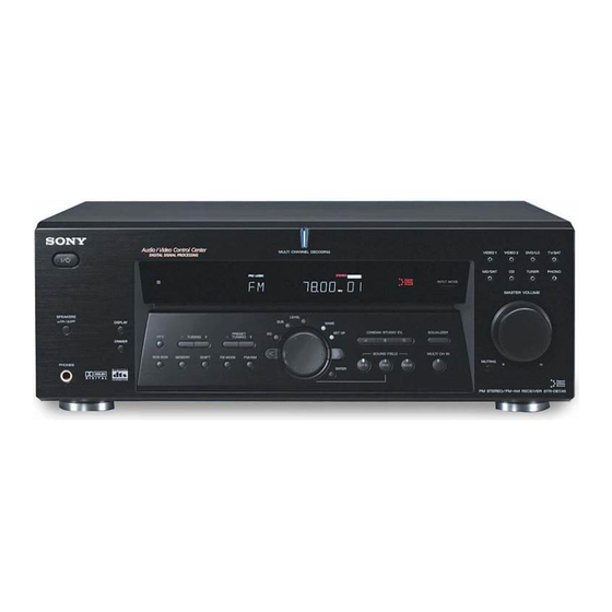
- Page 1 FM Stereo FM-AM Receiver Operating Instructions Manual de instrucciones STR-DE675 2001 Sony Corporation 4-233-599-32(4)
- Page 2 Do not use any type of abrasive pad, scouring powder or solvent such as alcohol or benzine. If you have any question or problem concerning your receiver, please consult your nearest Sony dealer.
-
Page 3: Table Of Contents
About This Manual The instructions in this manual is for model STR-DE675. Check your model number by looking at the lower right corner of the front panel. About area codes The area code of the player you purchased is shown on the lower portion of the rear panel (see the illustration below). -
Page 4: Hooking Up The Components
Hooking Up Components This chapter describes how to connect various audio and video components to the receiver. Be sure to read the sections for the components you have before you actually connect them to the receiver. Unpacking Check that you received the following items with the receiver: •... -
Page 5: Antenna Hookups
Antenna Hookups AM loop antenna (supplied) FM wire antenna (supplied) DIGITAL OPTICAL ANTENNA DVD/LD TV/SAT TAPE CTRL VIDEO IN TAPE COAXIAL DVD/LD COAXIAL S VIDEO CENTER FRONT SURROUND AUDIO IN WOOFER TV/SAT DVD/LD VIDEO 2 MD/TAPE MULTI CH IN Terminals for connecting the antennas Connect the To the AM loop antenna... -
Page 6: Audio Component Hookups
Audio Component Hookups MD/TAPE deck INPUT OUTPUT LINE DIGITAL OPTICAL ANTENNA DVD/LD TV/SAT TAPE CTRL VIDEO IN TAPE COAXIAL DVD/LD COAXIAL S VIDEO CENTER FRONT SURROUND AUDIO IN WOOFER TV/SAT DVD/LD VIDEO 2 MD/TAPE MULTI CH IN OUTPUT LINE CD player Jacks for connecting audio components Connect a To the... -
Page 7: Video Component Hookups
Video Component Hookups TV or Satellite tuner DVD or LD player S-VIDEO OUTPUT OUTPUT AUDIO OUT VIDEO AUDIO OUT VIDEO DIGITAL OPTICAL ANTENNA DVD/LD TV/SAT TAPE CTRL VIDEO IN VIDEO IN TAPE COAXIAL DVD/LD COAXIAL S VIDEO S VIDEO CENTER AUDIO IN AUDIO IN FRONT... -
Page 8: Digital Component Hookups
You can also connect an LD player with an RF OUT jack via an RF demodulator, such as the Sony MOD-RF1 (not supplied). DVD player (etc.)*... - Page 9 Connect the digital output jacks of your MD or tape deck to the receiver’s digital input jack and connect the digital input jacks of your MD or tape deck to the receiver’s digital output jack. These connections allow you to make digital recordings of a CDs played back through your DVD (or LD player) and satellite broadcasts.
-
Page 10: Multi Ch In Hookups
MULTI CH IN Hookups Although this receiver incorporates a multi channel decoder, it is also equipped with MULTI CH IN jacks. These connections allow you to enjoy multichannel software encoded in formats other than Dolby Digital and DTS. If your DVD player is equipped with MULTI CH OUTPUT jacks, you can connect them directly to the receiver to enjoy the sound of the DVD player’s multi channel decoder. -
Page 11: Other Hookups
Other Hookups CONTROL A1 DIGITAL OPTICAL ANTENNA DVD/LD TV/SAT TAPE CTRL VIDEO IN VIDEO IN TAPE COAXIAL DVD/LD COAXIAL S VIDEO S VIDEO CENTER FRONT SURROUND AUDIO IN AUDIO IN WOOFER TV/SAT DVD/LD VIDEO 2 MD/TAPE MULTI CH IN OUTPUT LINE CD player, tape deck, MD deck, etc. - Page 12 MD deck that is also connected to a computer, do not operate the receiver while using the “Sony MD Editor” software. This may cause a malfunction. • If you have a Sony CD changer with a COMMAND MODE selector If your CD changer’s COMMAND MODE selector can be set to CD 1, CD 2, or CD 3, be sure to set the command mode to “CD 1”...
-
Page 13: Speaker System
Hooking Up and Setting Up the Speaker System This chapter describes how to hook up your speaker system to the receiver, how to position each speaker, and how to set up your speakers to enjoy multi channel surround sound. SET UP Jog dial MULTI CHANNEL DECODING ? / 1... -
Page 14: Speaker System Hookup
Speaker System Hookup Required cords Speaker cords (not supplied) One for each front, surround, and center speaker (–) Monaural audio cord (not supplied) One for an active sub woofer Black DIGITAL OPTICAL ANTENNA DVD/LD TV/SAT TAPE CTRL VIDEO IN TAPE COAXIAL DVD/LD COAXIAL... - Page 15 To avoid short-circuiting the speakers Short-circuiting of the speakers may damage the receiver. To prevent this, make sure to take the following precautions when connecting the speakers. Make sure the stripped ends of each speaker cord does not touch another speaker terminal or the stripped end of another speaker cord.
-
Page 16: Performing Initial Setup Operations
Performing Initial Setup Operations Once you have made speaker connections and have turned on the power for the first time, clear the receiver’s memory. After you have done this, set the speaker sizes, speaker locations and other initial system settings that are necessary. -
Page 17: Multi Channel Surround Setup
You cannot change the configuration if you choose MICRO SP. The setting for Micro Satellite speaker (MICRO SP.) has been programmed to optimize the sound balance. If you use Sony’s Micro Satellite speakers, select MICRO SP. When you use Micro Satellite speaker and the speaker size is set to LARGE, you may not obtain the correct soundstage. - Page 18 Multi Channel Surround Setup p Front speaker size ( Initial setting : LARGE • If you connect large speakers that will effectively reproduce bass frequencies, select “LARGE”. Normally, select “LARGE”. • If the sound is distorted, or you feel a lack of surround effects when using multi channel surround sound, select “SMALL”...
- Page 19 p Surround speaker height ( Initial setting : HGT. LOW This parameter lets you specify the height of your surround speakers for proper implementation of the Digital Cinema Sound surround modes in the “VIRTUAL” sound fields. Refer to the illustration below. •...
- Page 20 Multi Channel Surround Setup About speaker distances This receiver allows you to input the speaker position in terms of distance. However, it is not possible to set the center speaker farther away than the front speakers. Also, the center speaker can not be set more that 1.5 meters (5 feet) closer than the front speakers.
-
Page 21: Before You Use Your Receiver
Notes • The front balance, surround balance, center level, and surround level are shown in the display during adjustment. • Although these adjustments can also be made via the front panel using the LEVEL menu (when the test tone is output, the receiver switches to the LEVEL menu automatically), we recommend you follow the procedure described above and adjust the speaker levels from your listening position using the... - Page 22 Before You Use Your Receiver There’s no sound from a specific component. , Check that the component is connected correctly to audio input jacks for that component. , Check that the cord(s) used for the connection is (are) fully inserted into the jacks on both the receiver and the component.
-
Page 23: Operations
Location of Parts and Basic Operations This chapter provides information about the locations and functions of the buttons and controls on the front panel. It also explains basic operations. Front Panel Parts Descriptions 1 ?/1 switch Press to turn the receiver on and off. 2 DISPLAY button Press repeatedly to change the information on the display window as follows:... - Page 24 Front Panel Parts Description ? / 1 DISPLAY SPEAKERS PRESET – TUNING DIMMER MEMORY SHIFT FM MODE PHONES 4 The following buttons operate the built-in tuner. For details, see “Receiving Broadcasts” starting from page PRESET TUNING +/– buttons Scan all preset stations. TUNING +/–...
- Page 25 8 INPUT MODE button Press to select the input mode for your digital components (DVD/LD, TV/SAT and MD/TAPE). Each press switches the input mode of the currently selected component. Select AUTO Give priority to digital signals when there are both digital and analog connections.
- Page 26 Front Panel Parts Description ? / 1 SPEAKERS DISPLAY PRESET – TUNING DIMMER MEMORY SHIFT PHONES qg EQ button Press to activate the equalizer parameters (page 36). The indicator on the button lights up and you can adjust the various equalizer parameters. qh SURR button Press to activate the surround parameters (page 34).
-
Page 27: Enjoying Surround Sound
The virtual sound modes contain compelling applications of the Sony Digital Cinema Sound digital signal processing technology. They shift the sound away from the actual speaker locations to simulate the presence of several “virtual”... -
Page 28: Selecting A Sound Field
SOUND FIELD LEVEL SURR MULTI CHANNEL DECODING ? / 1 LEVEL DISPLAY SPEAKERS SURR SET UP CINEMA STUDIO EX PRESET NAME – TUNING – TUNING DIMMER SOUND FIELD MEMORY SHIFT FM MODE A.F.D. MODE PHONES ENTER Cursor buttons EQUALIZER Jog dial Brief descriptions of buttons used to enjoy surround sound LEVEL button: Press to customize the level parameters. - Page 29 Software with two channel audio signals, is decoded with Dolby Pro Logic to create surround effects. C. ST. EX A Reproduces the sound characteristics of Sony Pictures 1)2) (CINEMA STUDIO EX. A) Entertainment’s classic editing studio by using the 3D (Press CINEMA STUDIO EX.
- Page 30 Selecting a Sound Field Sound field information Sound field Effect V. M.DIMENS. Uses 3D sound imaging to create an array of virtual (VIRTUAL MULTI DIMENSION) surround speakers positioned higher than the listener from a single pair of actual surround speakers. This mode creates four sets of virtual speakers surround the listener at approximately a 30°...
- Page 31 Use the buttons on the front panel to operate the following modes A.F.D. Automatically detects the type of audio signal being AUTO FORMAT DECODING input (Dolby Digital, Dolby Pro Logic, or standard two (Press the A.F.D. button) channel stereo) and performs the proper decoding if necessary.
-
Page 32: Understanding The Multi-Channel Surround Displays
Understanding the Multi-Channel Surround Displays DIGITAL SP. OFF COAX L F E SL S SR 1 ; DIGITAL This indicator lights up when the receiver is decoding signals recorded in the Dolby Digital format. 2 PRO LOGIC Lights up when the receiver applies Pro Logic processing to two channel signals in order to output the center and surround channel signals.* * However, this indicator does not light if the center and surround... - Page 33 Source sound displays The letters (L, C, R, etc.) indicate the source sound. The box around the letters varies to show how the receiver downmixes the source sound (based on the speakers settings). When using music sound modes such as SMALL HALL or JAZZ CLUB, the receiver adds reverberation based on the source sound.
-
Page 34: Customizing Sound Fields
Customizing Sound Fields By adjusting the surround parameters and the tone characteristics of the front speakers, you can customize the sound fields to suit your particular listening situation. Once you customize a sound field, the changes are stored in memory indefinitely (unless the receiver is unplugged for about one week). - Page 35 Adjusting the level parameters The LEVEL menu contains parameters that let you adjust the balance and speaker volumes of each speaker. The settings available in this menu are applied to all sound fields. Start playing a program source encoded with multi channel surround sound.
- Page 36 Customizing Sound Fields Dynamic range compressor ( D. RANGE Initial setting : COMP. OFF Lets you compress the dynamic range of the sound track. This may be useful when you want to watch movies at low volumes late at night. •...
- Page 37 Adjustable parameters for each sound field EFFECT LEVEL A.F.D. NORMAL SURROUND CINEMA STUDIO EX. A CINEMA STUDIO EX. B CINEMA STUDIO EX. C SEMI CINEMA STUDIO EX. A SEMI CINEMA STUDIO EX. B SEMI CINEMA STUDIO EX. C V. MULTI DIMENSION V.
-
Page 38: Receiving Broadcasts
Receiving Broadcasts This chapter describes how to receive FM or AM broadcasts and how to preset selected stations. You can tune in stations on this receiver in the following ways: Direct Tuning You can enter a frequency of the station you want directly by using the numeric buttons on the remote (see page 40). - Page 39 PRESET TUNING +/– TUNING +/– MEMORY MULTI CHANNEL DECODING ? / 1 INPUT MODE LEVEL SPEAKERS DISPLAY SURR SET UP CINEMA STUDIO EX EQUALIZER PRESET NAME – – TUNING TUNING DIMMER SOUND FIELD MULTI CH IN MEMORY SHIFT FM MODE A.F.D.
-
Page 40: Direct Tuning
Direct Tuning For details on the buttons used in this section, see “Brief descriptions of buttons used to receive broadcasts” on page 39. Press TUNER. The last received station is tuned in. Press FM or AM to select the FM or AM band. Press D.TUNING on the remote. -
Page 41: Preset Tuning
Preset Tuning For details on the buttons used in this section, see “Brief descriptions of buttons used to receive broadcasts” on page 39. Before tuning to preset stations, be sure to preset them by performing steps on “Presetting radio stations” below. Presetting radio stations Press TUNER. -
Page 42: Other Operations
Other Operations Cursor buttons NAME SET UP MULTI CHANNEL DECODING ? / 1 LEVEL DISPLAY SPEAKERS SURR SET UP CINEMA STUDIO EX PRESET NAME – TUNING – TUNING DIMMER SOUND FIELD MEMORY SHIFT FM MODE A.F.D. MODE PHONES ENTER Jog dial ENTER Brief descriptions of buttons that appear in this chapter... -
Page 43: Naming Preset Stations And Program Sources
Naming Preset Stations and Program Sources You can enter a name (index name) of up to 8 characters for preset stations and program sources. These names (for example, “VHS”) appear in the receiver’s display when a station or program source is selected. Note that no more than one name can be entered for each preset station or program source. -
Page 44: Using The Sleep Timer
Recording Recording on a video tape You can record from a TV, or an LD player using the receiver. You can also add audio from a variety of audio sources when editing a video tape. See your LD player’s instruction manual if you need help. Select the program source to be recorded. -
Page 45: Adjustment Using The Set Up Button
The CONTROL A1 control system has been updated to the CONTROL A1 which is the standard system in the SONY 300 disc CD changer and other recent Sony components. Components with CONTROL A1 jacks are compatible with components with CONTROL A1 , and can be connected to each other. - Page 46 Automatic function selection When you connect a CONTROL A1 compatible Sony amplifier (or receiver) to other Sony components using monaural mini-plug cords, the function selector on the...
-
Page 47: Additional Information
Also, see “Checking the connections” on page 21 to verify that the connections are correct. Should any problem persist, consult your nearest Sony dealer. There’s no sound or only a very low-level sound is heard. , Check that the speakers and components are connected securely. - Page 48 Troubleshooting No sound or only a very low-level sound is heard from the surround speakers. , Make sure the sound field function is on (press SOUND FIELD MODE). , Select the appropriate center mode (see pages 28 – 31). , Adjust the speaker volume (see page 20). , Make sure the surround speaker size parameter is set to either SMALL or LARGE (see page 18).
-
Page 49: Specifications
Specifications Amplifier section POWER OUTPUT Models of area code AR Rated Power Output at Stereo mode (8 ohms at 1 kHz, THD 0.7%) 100 W + 100 W Reference Power Output (8 ohms at 1 kHz, THD 10%) Front: 110 W/ch Center: 110 W Surround: 110 W/ch Models of area code MX... - Page 50 Specifications AM tuner section Tuning range 530 - 1610 kHz (10 kHz step) 531 - 1602 kHz (9 kHz step) Antenna Loop antenna Intermediate frequency 450 kHz Usable sensitivity 50 dB/m (at 999 kHz) 54 dB (at 50 mV/m) Harmonic distortion 0.5 % (50 mV/m, 400 Hz) Selectivity...
-
Page 51: Glossary
Digital Cinema Sound This is the generic name of the surround sound produced by digital signal processing technology developed by Sony. Unlike previous surround sound fields mainly directed at the reproduction of music, Digital Cinema Sound is designed specifically for the enjoyment of... - Page 52 Descripción de las indicaciones de sonido perimétrico multicanal SP. OFF L F E SL S SR 1 ; DIGITAL Este indicador se ilumina cuando el receptor está decodificando señales grabadas en formato Dolby Digital. 2 PRO LOGIC Se encenderá cuando esta unidad aplique el proceso Pro Logic a las señales de dos canales a fin de dar salida a señales para el canal central y los canales perimétricos.*...
-
Page 53: Remote Button Description
Remote Button Description You can use the remote to operate the components in your system. The tables below show the settings of each button. Remote Button Operations Function SLEEP Receiver Activates the sleep function and the duration which the receiver turns off automatically. - Page 54 TITLE DVD player Displays DVD title. ** Only for Sony TVs with the picture-in-picture function. Notes • Some functions explained in this section may not work depending on the model of the receiver. • The above explanation is intended to serve as an example only.
- Page 55 ENTER DSS (Digital Satellite Receiver) VCD player * Sony VCRs are operated with a VTR 1, 2 or 3 setting. These correspond to Beta, 8mm and VHS respectively. Now you can use the CD/SACD button to control the tape deck.
-
Page 56: Index
Index AC-3. See Dolby Digital (AC-3) Adjusting brightness of the display 23 speaker volumes 20 surround parameters 34 Automatic tuning 40 Basic receiver operations 23 - 26 Batteries 4 Changing display 23 effect level 34 Checking the connections 21 Clearing receiver’s memory 16 Connecting. - Page 57 No utilice ningún tipo de estropajos, polvos abrasivos, ni disolventes como alcohol o bencina. Si tiene cualquier pregunta o problema en relación con su receptor, consulte a su proveedor Sony más cercano.
-
Page 58: Acerca De Este Manual
Acerca de este manual Las instrucciones de este manual son para el modelo STR- DE675. Compruebe el número de su modelo en la esquina inferior derecha del panel frontal. Acerca de los códigos de área El código de área del reproductor que ha adquirido está indicado en la parte inferior del panel posterior (consulte la ilustración siguiente). - Page 59 Conexión de componentes En este capítulo se describe cómo conectar diversos equipos de audio y vídeo al receptor. Cerciórese de leer las secciones para los componentes que posea antes de conectarlos al receptor. Desembalaje Compruebe si ha recibido los accesorios siguientes con el receptor: •...
- Page 60 Conexión de antenas Antena de cuadro de AM (suministrada) Antena monofilar de FM (suministrada) DIGITAL OPTICAL ANTENNA DVD/LD TV/SAT TAPE CTRL VIDEO IN TAPE COAXIAL DVD/LD COAXIAL S VIDEO CENTER AUDIO IN FRONT SURROUND WOOFER TV/SAT DVD/LD VIDEO 2 MD/TAPE MULTI CH IN Terminales para conectar las antenas Conecte la...
- Page 61 Conexión de componentes de audio Deck de minidiscos/ cassettes INPUT OUTPUT LINE LINE DIGITAL OPTICAL ANTENNA DVD/LD TV/SAT TAPE CTRL VIDEO IN TAPE COAXIAL DVD/LD COAXIAL S VIDEO CENTER AUDIO IN FRONT SURROUND WOOFER TV/SAT DVD/LD VIDEO 2 MD/TAPE MULTI CH IN OUTPUT LINE Reproductor de discos...
- Page 62 Conexión de componentes de vídeo Sintonizador de Reproductor de TV o de satélite DVD o LD OUTPUT S-VIDEO OUTPUT AUDIO OUT VIDEO AUDIO OUT VIDEO DIGITAL OPTICAL ANTENNA DVD/LD TV/SAT TAPE CTRL VIDEO IN VIDEO IN TAPE COAXIAL DVD/LD COAXIAL S VIDEO S VIDEO CENTER...
- Page 63 (dos delanteros, otros dos sonido envolvente, y uno central) y otro de subgraves. Usted también podrá conectar un reproductor de discos láser provisto de toma RF OUT a través de un demodulador de RF, como el MOD-RF1 Sony (no suministrado). Reproductor de Sintonizador de videodiscos digitales TV o de satélite...
- Page 64 Conecte las tomas de salida digital de la platina de MD o de cassettes a la toma de entrada digital del receptor, y conecte las tomas de entrada digital de la platina de MD o de cintas a la toma de salida digital del receptor. Estas conexiones le permitirán realizar grabaciones digitales de discos compactos reproducidos a través de su reproductor de videodiscos digitales (o láser), y de programas de...
- Page 65 Conexión de MULTI CH IN Aunque este receptor incorpora un decodificador multicanal, dispone también de tomas MULTI CH IN. Estas conexiones le permitirán disfrutar de software multicanal codificado en formatos que no sean Dolby Digital y DTS. Si su reproductor de videodiscos digitales posee tomas MULTI CH OUTPUT, podrá...
- Page 66 Otras conexiones CONTROL A1 DIGITAL OPTICAL ANTENNA DVD/LD TV/SAT TAPE CTRL VIDEO IN VIDEO IN TAPE COAXIAL DVD/LD COAXIAL S VIDEO CENTER FRONT SURROUND AUDIO IN WOOFER TV/SAT DVD/LD VIDEO 2 MD/TAPE MULTI CH IN OUTPUT LINE Reproductor de discos compactos, deck de cassettes,...
- Page 67 Si ha realizado conexiones de CONTROL A1 un deck de minidiscos que también esté conectado a un PC, no utilice el receptor mientras esté usando el software “Sony MD Editor”. Esto podría causar un mal funcionamiento. • Si posee un cambiador de discos compactos...
- Page 68 Conexión y configuración del sistema de altavoces En este capítulo se describe cómo conectar su sistema de altavoces al receptor, cómo ubicar cada altavoz, y cómo configurar los altavoces para disfrutar de sonido perimétrico multicanal. SET UP Mando de lanzadera MULTI CHANNEL DECODING ? / 1 LEVEL...
- Page 69 Conexión del sistema de altavoces Cables requeridos Cables para altavoces (no suministrados) Un cable por cada altavoz, delanteros, sonido envolvente, y central. (–) Cable de audio monoaural (no suministrado) Uno para un altavoz de graves activo Negra DIGITAL OPTICAL ANTENNA DVD/LD TV/SAT TAPE...
- Page 70 Para evitar cortocircuitar los altavoces El cortocircuito de os altavoces puede dañar el receptor. Par evitar esto, cerciórese de tomar las precauciones siguientes cuando conecte los altavoces. Cerciórese de que los extremos de los conductores de cada cable de altavoces no toquen los terminales de otro altavoz ni el extremo pelado de otro conductor de cable de altavoz.
- Page 71 Realización de las operaciones de configuración inicial Después de haber realizado las conexiones de los altavoces y de haber conectado por primera vez la alimentación, borre la memoria. Después de esto, tendrá que ajustar los tamaños de los altavoces, su ubicación, y realizar otros ajustes iniciales del sistema.
- Page 72 El ajuste del altavoz Micro Satellite (MICRO SP.) está programado para optimizar el balance de sonido. Si utiliza los altavoces Micro Satellite de Sony, seleccione MICRO SP. Cuando utilice el altavoz Micro Satellite y el tamaño de altavoz esté ajustado en LARGE, es posible que no obtenga el sonido de baja frecuencia correcto.
- Page 73 Configuración del sonido perimétrico multicanal x Tamaño de los altavoces delanteros ( Ajuste inicial: LARGE • Si ha conectado altavoces grandes que reproduzcan efectivamente las frecuencias bajas, seleccione “LARGE”. Normalmente seleccione “LARGE”. • Si el sonido se oye distorsionado, o si nota la carencia de efecto perimétrico cuando utilice sonido perimétrico multicanal, seleccione “SMALL”...
- Page 74 x Altura de los sonido envolvente ( Ajuste inicial: HGT. LOW Este parámetro le permitirá especificar la altura de sus altavoces sonido envolvente para poder utilizar adecuadamente los modos perimétricos de Digital Cinema Sound en el género VIRTUAL. Consulte la ilustración siguiente.
- Page 75 Configuración del sonido perimétrico multicanal Acerca de las distancias de los altavoces Esta unidad le permitirá introducir la ubicación de los altavoces en términos de distancia. Sin embargo, no será posible ajustar el altavoz central más lejos que los altavoces delanteros. Además, el altavoz central no podrá...
- Page 76 Notas • El equilibrio entre los altavoces delanteros, sonido envolvente, y el nivel de los mismos se mostrará en el visualizador durante el ajuste. • Aunque estos ajustes también podrán realizarse a través del panel delantero utilizando el menú LEVEL (cuando esté saliendo el tono de prueba, el receptor cambiará...
- Page 77 Antes de utilizar su receptor No ha sonido a través de un componente específico. , Compruebe que el componente está correctamente conectado a las tomas de entrada de audio para ese componente. , Compruebe si las clavijas de los cables utilizados para los componentes están firmemente insertadas en las tomas, tanto del receptor como de dichos componentes.
- Page 78 Ubicación de partes y operaciones básicas En este capítulo se ofrece información sobre la ubicación y las funciones de las teclas y controles del panel frontal. También se explican las operaciones básicas. Descripción de las partes del panel frontal 1 Interruptor de alimentación (?/1) Presiónelo para conectar y desconectar la alimentación del receptor.
- Page 79 Descripción de las partes del panel frontal ? / 1 DISPLAY SPEAKERS PRESET – TUNING DIMMER MEMORY SHIFT FM MODE PHONES 4 Las teclas siguientes se utilizan para controlar el sintonizador incorporado. Con respecto a los detalles, consulte “Recepción de programas de radiodifusión” que se explica a partir de la página 38.
- Page 80 8 Tecla de modo de entrada (INPUT MODE) Presiónela para seleccionar el modo de entrada para sus componentes digitales (DVD/LD, TV/SAT y MD/ TAPE). Cada vez que presione la tecla, el modo de entrada del componente actualmente seleccionado cambiará. Seleccione para AUTO dar prioridad a las señales de...
- Page 81 Descripción de las partes del panel frontal ? / 1 DISPLAY SPEAKERS PRESET – TUNING DIMMER MEMORY SHIFT PHONES qg Tecla de ecualización (EQ) Presiónela para activar los parámetros del ecualizador (página 36). El indicador de la tecla se encenderá y usted podrá...
- Page 82 Los modos de sonido virtual contienen aplicaciones convincentes de la tecnología de proceso de señales digitales Digital Cinema Sound Sony. Estos modos desplazan el sonido fuera de las ubicaciones reales de los altavoces para simular la presencia de varios altavoces “virtuales”.
- Page 83 SOUND FIELD LEVEL SURR MULTI CHANNEL DECODING ? / 1 LEVEL DISPLAY SPEAKERS SURR SET UP CINEMA STUDIO EX PRESET NAME – TUNING – TUNING DIMMER SOUND FIELD MEMORY SHIFT FM MODE A.F.D. MODE PHONES ENTER Teclas del cursor ( Mando de lanzadera Descripción breve de las teclas utilizadas para disfrutar de sonido perimétrico...
- Page 84 Reproduce las características del estudio mezclador de C. ST. EX B 1)2) (CINEMA STUDIO EX. B) Sony Pictures Entertainment, que es una de las (Presione la tecla CINEMA instalaciones más innovadoras de Hollywood. La STUDIO EX. B.) imagen de sonido 3D de V.M.DIMENS. (página 30) se...
- Page 85 Selección de un campo acústico Información de campo de sonido Campo acústico Efecto V.M.DIMENS. Utiliza la formación de imagen de sonido (VIRTUAL MULTI tridimensional para crear un conjunto de altavoces DIMENSION) sonido envolvente virtuales ubicados a mayor (Dimensión múltiple virtual) altura que la del oyente desde un solo par de altavoces sonido envolvente reales.
- Page 86 Para utilizar los modos siguientes, use las teclas del panel frontal A.F.D. Detecta automáticamente el tipo de señal de audio que AUTO FORMAT DECODING eté introduciéndose (Dolby Digital, Dolby Pro Logic, o (Presione la tecla A.F.D.) estéreo de dos canales estándar) y realiza la decodificación adecuada si es necesario.
- Page 87 Descripción de las indicaciones de sonido perimétrico multicanal SP. OFF L F E SL S SR 1 ; DIGITAL Este indicador se ilumina cuando el receptor está decodificando señales grabadas en formato Dolby Digital. 2 PRO LOGIC Se encenderá cuando esta unidad aplique el proceso Pro Logic a las señales de dos canales a fin de dar salida a señales para el canal central y los canales perimétricos.*...
- Page 88 Indicaciones del sonido fuente Las letras (L, C, R, etc.) indican el sonido fuente. Los cuadros alrededor de las letras varían para mostrar la forma en la que el receptor mezcla el sonido fuente (basándose en la configuración de los altavoces). Cuando utilice modos de sonido de música como SMALL HALL o JAZZ CLUB, el receptor añadirá...
- Page 89 Personalización de los campos acústicos Si ajusta los parámetros de sonido perimétrico y las características de tono de los altavoces delanteros, podrá personalizar los campos de sonido según su situación particular de audición. Después de haber personalizado un campo acústico, los cambios se almacenarán permanentemente en la memoria (a menos que el receptor permanezca desenchufado durante una semana aproximadamente).
- Page 90 Ajuste de los parámetros de nivel El menú LEVEL contiene parámetros que le permitirán ajustar el equilibrio y el volumen de cada altavoz. Los ajustes disponibles en este menú se aplican a todos los campos acústicos. Ponga en reproducción unas fuente de programa codificado con sonido perimétrico multicanal.
- Page 91 Personalización de los campos acústicos Compresor de gama dinámica ( D. RANGE Ajuste inicial: COMP. OFF (desactivado) Le permitirá comprimir la gama dinámica de la pista de sonido. Esto puede resultar muy útil cuando desee contemplar películas a bajo volumen una vez entrada la noche. •...
- Page 92 Parámetros ajustables para cada campo acústico EFFECT LEVEL A.F.D. NORMAL SURROUND CINEMA STUDIO EX. A CINEMA STUDIO EX. B CINEMA STUDIO EX. C SEMI CINEMA STUDIO EX. A SEMI CINEMA STUDIO EX. B SEMI CINEMA STUDIO EX. C V. MULTI DIMENSION V.
- Page 93 Recepción de programas de radiodifusión En este capítulo se describe cómo recibir emisiones de FM o AM, y cómo memorizar emisoras. Usted podrá sintonizar emisoras con este receptor de las formas siguientes: Sintonía directa Usted podrá introducir directamente la frecuencia de la emisora que desee sintonizar utilizando las teclas numéricas el en mando a distancia (consulte la página 40).
- Page 94 PRESET TUNING +/– TUNING +/– MEMORY MULTI CHANNEL DECODING ? / 1 INPUT MODE LEVEL DISPLAY SPEAKERS SURR SET UP CINEMA STUDIO EX EQUALIZER PRESET NAME – TUNING – TUNING DIMMER SOUND FIELD MULTI CH IN MEMORY SHIFT FM MODE A.F.D.
- Page 95 Sintonía directa Con respecto a los detalles sobre las teclas utilizadas en esta sección, consulte “Descripción breve de las teclas utilizadas para recibir emisiones de radiodifusión” de la página 39. Presione TUNER. Se sintonizará la última emisora recibida. Presione FM o AM para seleccionar la banda de FM o AM.
- Page 96 Sintonía de emisoras memorizadas Con respecto a los detalles sobre las teclas utilizadas en esta sección, consulte “Descripción breve de las teclas utilizadas para recibir emisiones de radiodifusión” de la página 39. Antes de sintonizar emisoras memorizadas, cerciórese de memorizarlas realizando los pasos de “Memorización de emisoras de radiodifusión”, que se indica a continuación.
- Page 97 Otras operaciones Teclas del cursor ( NAME SET UP MULTI CHANNEL DECODING ? / 1 LEVEL SPEAKERS DISPLAY SURR SET UP CINEMA STUDIO EX PRESET NAME – – TUNING TUNING DIMMER SOUND FIELD MEMORY SHIFT FM MODE A.F.D. MODE PHONES ENTER Mando de lanzadera ENTER...
- Page 98 Asignación de nombres a emisoras memorizadas y de fuentes de programas Es posible asignar un nombre (nombre de índice) de hasta 8 caracteres para las emisoras memorizadas y fuentes de programa. Estos nombres de índices (por ejemplo, “VHS”) aparecerán en el visualizador del receptor cuando seleccione una emisora o una fuente de programas.
- Page 99 Grabación Grabación en una videocinta Usted podrá grabar de un televisor, o un reproductor de discos láser utilizando le receptor. También podrá añadir sonido de gran variedad de fuentes de audio cuando edite una videocinta. Si necesita ayuda, consulte el manual de instrucciones de su reproductor de discos láser.
- Page 100 Por consiguiente, las conexiones de CONTROL A1 entre un reproductor de discos compactos, un amplificador (receptor), deck de minidiscos y un deck de casetes Sony proporcionan la selección automática de funciones y la grabación sincronizada. En el futuro, las conexiones de CONTROL A1 trabajarán como un bus multifuncional que le permitirá...
- Page 101 Selección automática de función Cuando conecte un amplificador (o receptor) Sony compatible con CONTROL A1 utilizando cables con miniclavijas monoaurales, el selector de función del amplificador (o receptor) cambiará automáticamente a la entrada correcta cuando presione la tecla de reproducción...
- Page 102 21 para verificar si las conexiones son correctas. Si el problema persiste, póngase en contacto con su proveedor Sony. No hay sonido o solamente se oye a nivel muy bajo. , Compruebe si los altavoces y los componentes están conectados con seguridad.
- Page 103 Solución de problemas No hay sonido o solamente se oye a nivel muy bajo a través de los altavoces sonido envolvente. , Compruebe si la función de campo acústico está activada (presione SOUND FIELD MODE). , Seleccione el modo central apropiado (consulte las páginas 28 - 31).
- Page 104 Especificaciones Sección del amplificador SALIDA DE POTENCIA Modelos del código de área AR Salida de potencia nominal en el modo estéreo (8 ohmios, 1 kHz, THD 0,7%) 100 W + 100 W Salida de potencia de referencia (8 ohmios, 1 kHz, THD 10%) Altavoces delanteros: 110 W/canal...
- Page 105 Especificaciones Sección del sintonizador de AM Gama de sintonía 530 - 1 610 kHz (intervalo de 10 kHz) 531 - 1 602 kHz (intervalo de 9 kHz) Antena Antena de cuadro Frecuencia intermedia 450 kHz Sensibilidad útil 50 dB/m (a 999 kHz) Relación señal-ruido 54 dB (a 50 mV/m) Distorsión armónica...
- Page 106 Éste es el nombre genérico del sonido perimétrico producido por la tecnología de proceso de señales digitales desarrollada por Sony. A diferencia de los campos acústicos perimétricos anteriores, dedicados a la reproducción de música, Digital Cinema Sound fue diseñado exclusivamente para disfrutar de películas.
- Page 107 Ajustes con los botones SURR, LEVEL, EQ y SET UP Usted podrá realizar varios ajustes utilizando las teclas LEVEL, SURR, EQ, SET UP, el mando de lanzadera, y las del cursor. En las tablas siguientes se indican los ajustes que podrá realizar con estas teclas. Presione repetidamente para Presione que se encienda la...
- Page 108 Descripción de las teclas del telemando Es posible utilizar el mando a distancia para controlar los componentes del sistema. En las siguientes tablas se muestran los ajustes de cada botón. Tecla del Controla Función telemando SLEEP Receptor Activa la función de apagado automático y el intervalo tras el cual el receptor debe apagarse automáticamente.
- Page 109 Vuelve al menú anterior o edita el menú. TITLE Reproductor DVD Muestra el título del DVD. ** Solamente para televisores Sony con función de imagen en imagen. Nota • Determinadas funciones descritas en esta sección pueden no activarse en función del modelo de receptor.
- Page 110 DSS (Sistema de satélite digital) ENTER Reproductor de discos compactos de vídeo * Las videograbadoras Sony se controlan con el ajuste VTR 1, 2, o 3. Estos ajustes corresponden a Beta, 8 mm, y VHS, respectivamente. Ya puede utilizar el botón CD/SACD para controlar la platina de cintas.
- Page 111 8 CONTROL A1 entrada MULTI CH IN 10 cable de alimentación de CA sistemas de altavoces 14 CONTROL A1 11, 45 Sony Corporation Printed in Malaysia Denominación emisoras memorizadas 43 fuentes de programas 43 Desembalaje 4 Dolby Digital (AC-3) 51 Dolby Pro Logic Surround 51 Duplicación.