Table of Contents
Advertisement
Advertisement
Table of Contents

Related Manuals for Bosch Rexroth Marex SB


Summary of Contents for Bosch Rexroth Marex SB
- Page 1 Marex SB Manual / Marine Version 2.10 15.07.2003...
- Page 2 In case of malfunction, an error analysis as explained in chapter 6 has to be carried out. Imprint: The copyright of this user manual remains the property of Bosch Rexroth AG. Included are instructions and technical drawings which may not be reproduced or copied either in part or whole, nor may they be used for evaluation or distributed for competition purposes.
-
Page 3: Table Of Contents
Table of Contents Page 1 General 1.1 System components 1.2 General preconditions for the operation 1.3 Mounting advice 1.4 Operating advice 2 Overview 2.1 Single engine 2.2 Twin engine 3 Wiring 3.1 Voltage supply 3.2 Control head 3.3 Mechanical throttle control / gear shifting 3.4 Electrical throttle control / gear shifting 3.5 Alarm relays 3.6 Engine start interlock... -
Page 4: General
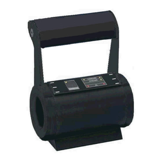
1 General 1.1 System components Designation Code No. Photo Symbol Control head 362 241 100 0 (single engine) Control head 362 241 000 0 (twin engine) Control unit 346 068 000 0 DC actuator 323 698 020 0 I/O-extension board 346 068 721 2 Synchro-board 346 068 730 2... -
Page 5: General Preconditions For The Operation
1.2 General preconditions for the operation (According to classification rules) Indication of the current cruising command* The current cruising command (speed, gearing position) must be indicated on every control station. Indication of active control station* It must be indicated on every control station which control station is in command. If, from any control station, any other station is visible, the indication of current cruising command and active control station is not necessary (e. -
Page 6: Single Engine
2 Overview 2.1 Single engine Single engine – mechanical throttle control and gear shifting Throttle and gear shifting are operated by mechanical rods. SYSCON shielded cable type LIYCY 4 x 1 mm 70 mm 100 N 70 mm 100 N Single engine - electrical throttle control, mechanical gear shifting The throttle is adjusted electrically (4 ... - Page 7 Single engine - mechanical throttle control, electrical gear shifting Throttle is actuated by mechanical rods, gear shifting is controlled by 24 V-signals. SYSCON shielded cable type LIYCY 4 x 1 mm shielded cable 70 mm type LIYCY 100 N 7 x 1 mm 24 V Single engine –...
-
Page 8: Twin Engine
2.2 Twin engine Twin engine – mechanical throttle control, mechanical gear shifting Throttle and gear shifting are controlled by mechanical rods. SYSCON SYSCON port starboard shielded cable type LIYCY 4 x 1 mm shielded cable type LIYCY 70 mm 70 mm 2 (4) x 1 mm 100 N 100 N... - Page 9 Twin engine – mechanical throttle control, electrical gear shifting Throttle is adjusted by means of mechanical rods, gear shifting is controlled by 24 V-signals. I/O-extension board SYSCON actuation gearing port I/O-extension board actuation gearing starboard shielded port starboard cable type LIYCY 4 x 1 mm 70 mm 70 mm...
-
Page 10: Voltage Supply
3 Wiring 3.1 Voltage supply voltage voltage voltage 12...24 V DC 12 V DC 24 V DC switch for configuration of engine type (see chapter 2 overview) supply line 2,5mm length. 10m max screened LED - readyness 12V / 24V DC fuse main 10 A nominal current... - Page 11 Entering the identification (ID) To enable the control to identify the control heads, an individual ID must be entered once at every control head (e. g. control head bridge ID 1, control head port ID 2, control head starboard ID 3) ID 0 is not admissible.
- Page 12 Wiring control head optional switch: station tranfer interlock The IDs of the control heads (required for ECR stations according to classification rules) must be different. control head control head control head ID 1 ID 2 ID 3 bridge at last head screened line (LIYCY)
-
Page 13: Mechanical Throttle Control / Gear Shifting
3.3 Mechanical throttle control and gear shifting actuator actuator SYSCON The setting of switchboard SYSCON (switches 1 – 6) assigns the function (speed or gear control) to the actuators (see chapter 2 overview). 3.3.1 Push-/pull-cable The mechanical connection between actuator and lever for throttle adjustment or gear control at the engine is done by push-/pull-cables. -
Page 14: Electrical Throttle Control / Gear Shifting
3.3.2 Mounting of the actuator Mounting work may only be carried out if the actuator is idle. Risk of injury! 3.3.3. Connection at the throttle and gear adjusting lever To fix the push-/pull-cable at the adjusting lever, a ball joint may be used. "s"... - Page 15 Electrical gear shifting without feedback Indication gear condition screened cable type LIYCY 7 x 1 mm grounded at both ends LED set ahead (73) LED set astern (75) ahead astern Vcc, 2A Vcc, 2A solenoid valve gear feedback relay with free-wheeling diode Solenoid valve not included in MAREX SB delivery.
- Page 16 Electrical gear shifting with separate feedback Indication gear condition screened cable type LIYCY, 7 x 1 mm grounded at both ends LED set ahead (73) LED set astern (75) LED act. astern (78) LED act. astern (76) Voraus Zurück Vcc, 2A Vcc, 2A solenoid valve with free-wheeling diodes...
- Page 17 Power supply for electrical gear shifting fuse 2A T supply line 2 x 1 mm length max. 10m The power supply shown above is recommended according to the classification rules. Alternatively, the control unit may supply the voltage for the electrical gear control: 71 72 When the control unit supplies the voltage for the electrical gear control, the power supply is not protected by fuse.
-
Page 18: Alarm Relays
Mounting the I/O-extension boards X101 X102 viewing direction I/O-extension board II (actuation starboard X101 X102 control unit I/O-extension board I (actuation port 3.5 Alarm relays potential-free relay contact closed in case of error max. 30 V DC max. 0,5 shielded cable LED alarm relay type LIYCY 2 x 0,75 mm... -
Page 19: Engine Start Interlock
3.6 Engine start interlock single engine twin engine configuration start interlock shielded cable shielded cable type LIYCY type LIYCY 2 x 0,75 mm 2 x 0,75 mm supply battery starter- engine engine battery engine port starboard connection to connection to I/O-extension board 1 I/O-extension board 2 The relay "start interlock"... - Page 20 Two special cases must be considered when wiring the engine start interlock Engine start interlock, special application 1: Twin engine with mechanical throttle control and gear shifting port starboard port starboard shielded cable shielded cable type LIYCY type LIYCY 2 x 0,75 mm 2 x 0,75 mm engine engine...
-
Page 21: Idle Gas Relay
3.7 Idle gas relay Single Engine Twin Engine idle gas idle gas port idle gas starboard The idle gas relay is closed when the lever of the active control head is in neutral or in 1 detent ahead/astern. Wiring I/O-extension board closed when, potential-free lever in neutral or... -
Page 22: Hardware Configuration
4 Adjustment 4.1 Hardware configuration Possibilities of adjusting the control unit see chapter 4.4 "gearing" SYSCON TIME delay time before clutch configuration of system type delay time after clutch see chapter 2 "overview" reversing delay time set voltage supply see chapter 3 "wiring" 3.1 "voltage supply"... -
Page 23: Control Head
4.2 Control head Introducing the control heads In order to inform the control about the number of control heads connected, these must be introduced. For twin engine controls with mechanical throttle control and gear shifting, the procedure has to be carried out at the portside system. - Page 24 Procedure for automatic ID-setting Step Action Diagram Activate control. Hold down switch S1. switch S1 Shift CTRHEAD switch 1 to close. CTRHEAD Do not further operate switch S1. switch S1 The control head buzzers sound at short intervals. In addition, the control head LEDs are active (see step 6) and flash in the same frequency as the buzzer.
- Page 25 ID Indication LED off LED steadily lighted LED flashing no ID assigned no automatic ID set yet ID 5 ID 1 ID 2 ID 3 ID 4 Shift CTRHEAD switch 1 to open. CTRHEAD Buzzer in neutral When the lever of the active control head is moved to neutral, a short buzzer sound can signal this. Short sound, when lever in neutral CTRHEAD (With two control units, only the port unit must be adjusted.)
-
Page 26: Speed
Synchronising Synchronising active If the lever positions of the port and starboard control heads CTRHEAD deviate at 10% maximum, the same nominal value will be preset automatically. No synchronizing (default condition) CTRHEAD 4.3 Speed setting Generally, the parameters for speed setting can be set when the active control head is in neutral position. - Page 27 Selection of the system for which speed parameters shall be set PARSEL for single engines or twin engines: port system for twin engines: starboard system PARSEL During step 4, it is possible the engine revolutions adjust automatically. Change to SETUP-mode PARSEL LED Setup The selected position will be reached.
-
Page 28: Gearing
4.4 Gearing Positions for actuating the mechanical gear shifting The push-/pull-cables at the actuators must be mounted in such a way that the neutral position of the gear system is actuated when the active lever is placed in neutral. For systems configurated with 2 control units (mechanical throttle control and gear shifting) each control unit must be set separately. - Page 29 During step 4, it is possible that the gear position adjusts automatically, the driving engine should therefore be turned off. Change to SETUP-mode PARSEL LED Setup The selected position will be reached. LED Setup will be activated. Adjusting the gear position PARSEL Direction + Position is adjusted as long as the key is pushed.
- Page 30 Conditions when reversing from ahead to astern: When reversing from ahead to astern, the gearing is at first shifted to neutral, the shaft is disengaged from the engine (1). As the ship continues to move ahead, the propeller is driven like a windmill by the water streaming against it so that the shaft continues to turn.
-
Page 31: Reset To Default
4.5 Reset to default Resetting to default will reset the speed and gearing control values to their delivery status. This procedure is irreversible. A reset to default may be done only if the driving engine is turned off. In case of mechanical controlling, the push-/pull-cables should be disconnected. -
Page 32: General
5 Operation 5.1 General By means of the lever position both, 1. detent 1. detent neutral ahead astern speed and gear position, (ahead, neutral, astern) are pre-set. disengaged engaged engaged ahead astern full full ahead astern The following elements are available as user interfaces: Keys Command lamp •... -
Page 33: Activation And Request Control Station
5.2 Activation and request of control station After switching on the power supply, all control heads which work correctly are in condition "lamp test" (all lamps and buzzer on). The command can be requested from every control station by pressing the key once. -
Page 34: Station Transfer
5.3 Station transfer A command transfer is possible in 2 different modes. Which mode is applicable, depends on the position of switch 3 on the switch board CTRHEAD (see chapter 4.2 control head – comparision of range / position). Always, the key on the passive control station must be pushed to change the control station. -
Page 35: Warming Up
5.4 Warming up By means of the special function "warming up" a determined speed can be set without gear shifting. This function is necessary to warm up the engines. To activate "warming up", the key must be pushed at the active control station and, at the same time, the lever moved in ahead or astern. - Page 36 6 Error analysis 6.1 Errors at the control station Two errors at the control stations must be distinguished: Alarm During an alarm, the setting of the cruising active station functions (speed or gearing) is disturbed. On COMMAND the active control head, the red alarm lamp will ALARM be on and a buzzer will sound.
- Page 37 6.2 Error indication control unit To indicate errors, 4 error LEDs are available LED RUN LED SETUP altogether. The top LED is red to facilitate error orientation. The operation mode of the control is indicated by 2 additional LEDs (RUN, SETUP). By pressing a key, further error messages can be displayed.
- Page 38 Error type: ACTUATOR 1 Error description: The system is configurated ( see chapter 2) in such a way that actuator 1 (see chapter 3.3) directs mechanical gear shifting or speed setting. However, the control states an error in the operation of the actuator. Error elimination: Check the plugs of actuator 1 for correct connection to the board of the control unit (see chapter 3.3).
- Page 39 Red LED 1 flashing Error type: SYN-CARD (warning only) Error description: No extension board for synchronizing found. Error elimination: Check cable from synchronizing board to board of the control unit (see instructions attached to the synchronizing board). If necessary, replace synchronizing board. Error type: SYN-SIG (warning only) Error description: The synchronizing board cannot measure the speed correctly.
- Page 40 Error type: TWIN Error description: The system was configurated for twin engines – mechanical gear shifting and speed setting (chapter 2). The communication between the control units port and starboard does not function. Error elimination: Check cable between the control units and the necessary bridges (see chapter 3.2 –...
- Page 41 Mode RUN or SETUP (LED RUN or LED SETUP on) Error type: GEAR MASTER Error description: Gear feedback has been set at the I/O-extension board (see chapter 3.4). The gear feedback is not signalled (for twin engines on the port side). The system works without gear feedback.
- Page 42 Error type: CTRL-POS Error description: Before adjusting parameters for speed and gear control, the active control head must be placed in the correct position (see chapter 4.3 or 4.4). It is not permitted to adjust the parameter in this lever position. Error elimination: Change to RUN-mode (step 1 in chapter 4.3 or 4.4).
-
Page 43: Control Unit
Control Unit – In- and Outputs... - Page 44 Control Unit - Terminals...
- Page 48 Rexroth Mecman GmbH Bartweg 13 D-30453 Hannover Phone: +49 – 5 11 – 21 36 – 0 Fax: +49 – 5 11 – 21 36 – 2 69 www.boschrexroth.com Subject to alteration. This edition supersedes all previous ones. Printed in Germany. No part of this edition may be repro-duced without our prior permission.