Table of Contents
Advertisement
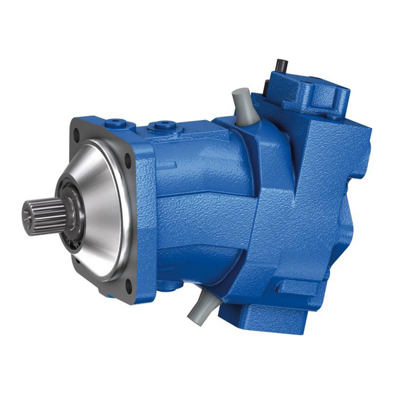
A7VO Series 63
Characteristics
▶ Variable pump with axial tapered piston rotary group of
bent-axis design, for hydrostatic drives in open circuit
▶ For use in mobile and stationary applications
▶ Flow is proportional to the drive speed and displace-
ment.
▶ The flow can be steplessly changed by adjusting the
bent axis.
▶ Wide selection of control devices
▶ Compact, robust pump with a long service life
▶ Sizes 28 to 160
▶ Nominal pressure 350 bar
▶ Maximum pressure 400 bar
▶ Open circuit
Contents
RE 92202
Edition: 02.2015
Replaces: 05.2012
RE 92202/02.2015, Bosch Rexroth AG
2
4
5
5
6
7
9
13
15
18
20
21
24
28
32
36
40
41
42
42
Advertisement
Table of Contents

Related Manuals for Bosch Rexroth A7VO 63 Series


Summary of Contents for Bosch Rexroth A7VO 63 Series
-
Page 1: Table Of Contents
HD – Proportional hydraulic control EP – Proportional electric control Dimensions, size 28 Dimensions, size 55 Dimensions, size 80 Dimensions, size 107 Dimensions, size 160 Connector for solenoids Installation instructions Project planning notes Safety instructions RE 92202/02.2015, Bosch Rexroth AG... - Page 2 SAE flange ports A and S at rear (metric fastening thread) SAE flange ports A and S at side (available for power controllers LA1S and LA1S5 only, metric fastening thread) – = Not available ● = Available = Preferred program Bosch Rexroth AG, RE 92202/02.2015...
-
Page 3: Axial Piston Variable Pump | A7Vo Series 63
▶ Note the project planning notes on page 42! ▶ Preservation: – Up to 12 months as standard – Up to 24 months long-term (state in plain text when ordering) Connectors for other electric components may differ RE 92202/02.2015, Bosch Rexroth AG... -
Page 4: Hydraulic Fluids
▼ Selection diagram Warm-up phase Maximum permissible viscosity for cold start 1600 1000 Range of optimum operating viscosity v Optimum efficiency Minimum permissible viscosity for short-term operation Minimum permissible temperature for cold start Temperature θ [°C] Bosch Rexroth AG, RE 92202/02.2015... -
Page 5: Shaft Seal Ring
-25 °C to +115 °C. For application cases below -25 °C, an NBR shaft seal is required (permissible temperature range: -40 °C to +90 °C). Flow direction Direction of rotation, viewed on drive shaft clockwise counter-clockwise S to B S to A RE 92202/02.2015, Bosch Rexroth AG... -
Page 6: Operating Pressure Range
Minimum pressure (high pressure side) Time t Total operating period = t + ... + t Note Operating pressure range valid when using hydraulic fluids based on mineral oils. Values for other hydraulic fluids, please contact us. Bosch Rexroth AG, RE 92202/02.2015... -
Page 7: Technical Data
= 36 to 16 mm ‒ For hydraulic fluid based on mineral oils. Maximum rotational speed (speed limit) for increased inlet pressure p at suction port S and V < V , see diagram. g max RE 92202/02.2015, Bosch Rexroth AG... - Page 8 Recommended position of mating gear is depen- Please contact us. dent on direction of rotation. Example: ▼ Gear drive 1 “Clockwise” rotation, pressure at port B 2 “Counter-clockwise” rotation, pressure at port A With intermittent operation Bosch Rexroth AG, RE 92202/02.2015...
-
Page 9: Lr - Power Controller Without Power Override
When ordering, state in plain text: ▶ Drive power P [kW] ▶ Drive speed n [rpm] g min ▶ Maximum flow q [l/min] v max g max Please contact us if you need a power diagram. RE 92202/02.2015, Bosch Rexroth AG... - Page 10 ▶ Any pressure-relief valve included in the system to limit the maximum pressure must have its start of opening at least 20 bar above the pressure cut-off setting. g min g max Bosch Rexroth AG, RE 92202/02.2015...
- Page 11 When ordering, state the start of control in plain text. ▶ Initial position without pilot signal (pilot pressure): V g max ▼ Characteristic curve LRH1 B(A) control pressure increase (V – V ) Δp = 25 bar g max g min g min g max Displacement V g max RE 92202/02.2015, Bosch Rexroth AG...
- Page 12 Δp setting. In an LUDV system, the pressure cut-off is integrated in the flow sharing control block (LUDV). The measuring orifice (control block) (1) is not included in the scope of delivery. Bosch Rexroth AG, RE 92202/02.2015...
-
Page 13: La1 - Power Controller With Hydraulically Proportional Power Override
When ordering, state in plain text: ▶ Drive power P [kW] ▶ Drive speed n [rpm] ▶ Maximum volume flow q [l/min] V max Please contact us if you need a power diagram. RE 92202/02.2015, Bosch Rexroth AG... - Page 14 Increasing pilot pressure = lower Δp setting. An example of this is shown in the characteristic curve below. Please consult us before carrying out project planning. ▼ Characteristic curve LA1S5 Pilot pressure p [bar] ▼ Schematic LA1S5 g min g max Bosch Rexroth AG, RE 92202/02.2015...
-
Page 15: Dr - Pressure Controller
In the case of longer zero-stroke operation (> 1 min), bearing flushing should be carried out via flushing port U. Flow port flow q [l/min] V min V max Flushing flow (recommended) l/min V flush Temperature of flushing fluid ≤ reservoir temperature RE 92202/02.2015, Bosch Rexroth AG... - Page 16 20 bar above the controller setting. You must order the sequence valve and the port plate separately. ▶ Sequence valve (1): DZ5DP2-1X/315YMSO21 (Material number R900495604) ▶ Port plate (2): G 115/1 (Material number R900424379) g min g max Bosch Rexroth AG, RE 92202/02.2015...
- Page 17 [l/min] V min V max ▼ Schematic DRS g min g max The measuring orifice (control block) (1) is not included in the scope of delivery. RE 92202/02.2015, Bosch Rexroth AG...
-
Page 18: Hd - Proportional Hydraulic Control
To ensure that control is guaranteed at a low operating g max pressure of < 40 bar too, port Y must be supplied with an external control pressure of about 40 bar. ▼ Schematic HD B(A) g min g max Bosch Rexroth AG, RE 92202/02.2015... - Page 19 20 bar above the controller setting. B(X) You must order the sequence valve and the port plate separately. B(A) ▶ Sequence valve (1): DZ5DP2-1X/315XYMSO20 (Material number R900490554) g min ▶ Port plate (2): G 115/1 g max (Material number R900424379) RE 92202/02.2015, Bosch Rexroth AG...
-
Page 20: Ep - Proportional Electric Control
Voltage 24 V (±20%) Control current Start of control 200 mA End of control 600 mA Current limit 0.77 A Nominal resistance (at 20 °C) 22.7 Ω Dither frequency 100 Hz Duty cycle 100% Type of protection: see connector version page 40 Bosch Rexroth AG, RE 92202/02.2015... -
Page 21: Dimensions, Size 28
All of the variants of the controllers on page 23 are shown for the clockwise direction of input rotation (view Y) 209 (A 13.4 max 209 (X Flange ISO 3019-2 View Y Clockwise rotation View Y Counter-clockwise rotation 35.7 23.8 108.5 To shaft collar RE 92202/02.2015, Bosch Rexroth AG... - Page 22 T to the reservoir. fittings. O = Must be connected (plugged on delivery) Only dimensions according to SAE J518, metric fastening thread is X = Plugged (in normal operation) a deviation from the standard. Bosch Rexroth AG, RE 92202/02.2015...
- Page 23 ▼ HD1, HD1G – Proportional hydraulic control , positive control, ▼ EP2 – Proportional control electric, positive control and variant with pressure cut-off, remotely controlled 155 (X 159 (Y 159 (Y 187 (A 187 (A 188 (X 188 (X RE 92202/02.2015, Bosch Rexroth AG...
-
Page 24: Dimensions, Size 55
All of the variants of the controllers on pages 26 and 27 are shown for the clockwise direction of input rotation (view Y) 14.6 max Flange ISO 3019-2 View Y Clockwise rotation View Y Counter-clockwise rotation 23.8 42.9 To shaft collar Bosch Rexroth AG, RE 92202/02.2015... - Page 25 Keep this in mind when selecting measuring devices and to the reservoir. fittings. O = Must be connected (plugged on delivery) Only dimensions according to SAE J518, metric fastening thread is X = Plugged (in normal operation) a deviation from the standard. RE 92202/02.2015, Bosch Rexroth AG...
- Page 26 ▼ LA1S – Power control with load sensing, LA1S5 – Power control with load sensing and hydraulically proportional LS-override 257 (X 252 (Y B (S) 183 (B) 184 (S) Port X with version LA1S5 only Bosch Rexroth AG, RE 92202/02.2015...
- Page 27 ▼ HD1, HD1G – Proportional hydraulic control , positive control, ▼ EP2 – Proportional control electric, positive control and variant with pressure cut-off, remotely controlled 186 (X 190 (Y 190 (Y 209 (A 209 (A 221 (X 221 (X RE 92202/02.2015, Bosch Rexroth AG...
-
Page 28: Dimensions, Size 80
All of the variants of the controllers on pages 30 and 31 are shown for the clockwise direction of input rotation (view Y) 14.6 max Flange ISO 3019-2 View Y Clockwise rotation View Y Counter-clockwise rotation 27.8 50.8 To shaft collar Bosch Rexroth AG, RE 92202/02.2015... - Page 29 T to the reservoir. fittings. O = Must be connected (plugged on delivery) Only dimensions according to SAE J518, metric fastening thread is X = Plugged (in normal operation) a deviation from the standard. RE 92202/02.2015, Bosch Rexroth AG...
- Page 30 ▼ LA1S – Power control with load sensing, LA1S5 – Power control with load sensing, can be overridden on a hydraulically proportional basis 284 (X 279 (Y B (S) 209 (B) 210 (S) Port X with version LA1S5 only Bosch Rexroth AG, RE 92202/02.2015...
- Page 31 ▼ HD1, HD1G – Proportional hydraulic control , positive control, ▼ EP2 – Proportional control electric, positive control and variant with pressure cut-off, remotely controlled 207 (X 212 (Y 212 (Y 237 (A 237 (A 241 (X 241 (X RE 92202/02.2015, Bosch Rexroth AG...
-
Page 32: Dimensions, Size 107
All of the variants of the controllers on pages 34 and 35 are shown for the clockwise direction of input rotation (view Y) 14.6 max Flange ISO 3019-2 View Y Clockwise rotation View Y Counter-clockwise rotation 27.8 50.8 To shaft collar Bosch Rexroth AG, RE 92202/02.2015... - Page 33 T to the reservoir. fittings. O = Must be connected (plugged on delivery) Only dimensions according to SAE J518, metric fastening thread is X = Plugged (in normal operation) a deviation from the standard. RE 92202/02.2015, Bosch Rexroth AG...
- Page 34 ▼ LRD – Power controller with pressure cut-off ▼ LRDS – Power control with pressure cut-off and load sensing 290 (X ▼ LRDH1 – Power control with pressure cut-off and stroke limiter 300 (X 295 (Y Bosch Rexroth AG, RE 92202/02.2015...
- Page 35 ▼ HD1, HD1G – Proportional hydraulic control , positive control, ▼ EP2 – Proportional control electric, positive control and variant with pressure cut-off, remotely controlled 220 (X 225 (Y 225 (Y 254 (A 254 (A 259 (X 259 (X RE 92202/02.2015, Bosch Rexroth AG...
-
Page 36: Dimensions, Size 160
All of the variants of the controllers on pages 38 and 39 are shown for the clockwise direction of input rotation (view Y) 328 (T 14.9 max 327 (X Flange 331 (A ISO 3019-2 View Y Clockwise rotation View Y Counter-clockwise rotation 31.8 61.9 To shaft collar Bosch Rexroth AG, RE 92202/02.2015... - Page 37 T to the reservoir. fittings. O = Must be connected (plugged on delivery) Only dimensions according to SAE J518, metric fastening thread is X = Plugged (in normal operation) a deviation from the standard. RE 92202/02.2015, Bosch Rexroth AG...
- Page 38 ▼ LRD – Power controller with pressure cut-off ▼ LRDS – Power control with pressure cut-off and load sensing 329 (X ▼ LRDH1 – Power control with pressure cut-off and stroke limiter 340 (X 334 (Y Bosch Rexroth AG, RE 92202/02.2015...
- Page 39 ▼ HD1, HD1G – Proportional hydraulic control , positive control, ▼ EP2 – Proportional control electric, positive control and variant with pressure cut-off, remotely controlled 249 (X 253 (Y 253 (Y 290 (A 290 (A 294 (X 294 (X RE 92202/02.2015, Bosch Rexroth AG...
-
Page 40: Connector For Solenoids
2 sockets 0462-201-16141 The mating connector is not included in the scope of delivery. This can be supplied by Bosch Rexroth on request (material number R902601804). Note If necessary, you can change the connector orientation by turning the solenoid housing. -
Page 41: Installation Instructions
Air bleed port Bearing flushing Suction port Control fluid drain Minimum required immersion depth (200 mm) t min Minimum required spacing to reservoir base (100 mm) Baffle (baffle plate) RE 92202/02.2015, Bosch Rexroth AG... -
Page 42: Project Planning Notes
© This document, as well as the data, specifications and other information set Mobile Applications forth in it, are the exclusive property of Bosch Rexroth AG. It may not be Glockeraustrasse 4 reproduced or given to third parties without its consent. The data specified 89275 Elchingen, Germany above only serve to describe the product.