Table of Contents
Advertisement
Quick Links
Advertisement
Table of Contents

Related Manuals for ABB UMC22-FBP


Summary of Contents for ABB UMC22-FBP
- Page 1 Technical Description FBP FieldBusPlug Universal Motor Controller UMC22-FBP Software version 4.0 UMC22 READY MOT .ON F AUL T EXT .
-
Page 2: Table Of Contents
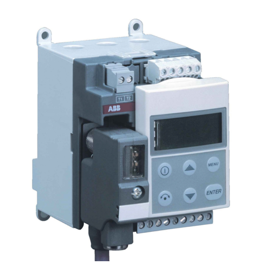
FAULT Relay 230V AC Inputs Power 24VDC Fig. 1: Universal Motor Controller UMC22-FBP 0. Content 1. Introduction and features ........................5 1.1 How to use this document ......................5 1.2 Overview of the features .......................6 1.3 Construction ..........................6 1.4 Overload protection ........................7 1.5 Other features ..........................7... - Page 3 Universal Motor Controller UMC22-FBP Software version 4.0 Chapter 0~2 2. Device construction ..........................11 2.1 Overview .............................11 2.2 Terminals, monitoring LEDs and operating elements on the front plate ........12 3. Planning, commissioning and maintenance ..................13 3.1 Commissioning steps .........................13 3.1.1 Step 1: Wiring ........................13 3.1.2 Step 2: Interfacing to the fi...
- Page 4 Universal Motor Controller UMC22-FBP Software version 4.0 Chapter 0~3 4.3.3 Transfer of the complete parameter set in one block............49 4.3.4 Parameter - Details in alphabetical order ................51 5. Technical data ............................69 5.1 Main power lines .........................69 5.2 Controller unit ..........................71 5.3 Digital inputs ..........................72...
-
Page 5: Introduction And Features
Universal Motor Controller UMC22-FBP Software version 4.0 Chapter 1.1~1 1. Introduction and features 1.1 How to use this document A particular motor feeder shall be planned and realized: Select the dedicated part in this document (examples): Direct starter see chapter 7.3.3 Reversing starter see chapter 7.3.4... -
Page 6: Overview Of The Features
fi eldbus connection (7.2.1). The other control functions can be used stand alone also. 1.3 Construction The UMC22-FBP consists of two separate parts: current transformer unit and controller unit, mounted as one device (2.1). Mounting on DIN rail or with screws. W x H x D = 70 x 105 x 110 mm. -
Page 7: Overload Protection
Universal Motor Controller UMC22-FBP Software version 4.0 Chapter 1.4~1 and 1.5~1 1.4 Overload protection Measuring the motor current. The value is displayed on the Control Panel (8.1.3) and provided also to be sent to the fi eldbus) (4.2.1). Electronic overload protection for nominal currents of 0.24 A to 63 A (whole range with onIy one UMC22 type). -
Page 8: New Features In Comparison To Preceeding Versions
Universal Motor Controller UMC22-FBP Software version 4.0 Chapter 1.6~1 1.6 New features in comparison to preceeding versions 1.6.1 Version 3.0 3.10 Parameter Current factor: Monitoring of the real Set current when using external current transformers and / or 3 (inner delta) circuitry (4.3.4, 3.2.3, 3.2.4). -
Page 9: Version
Universal Motor Controller UMC22-FBP Software version 4.0 Chapter 1.6~2 1.6.4 Version 3.31 PTC input: Terminals T1 and T2 can be used to connect PTC sensors (3.6). PTC protection with warning or trip function can be activated via parameter 6 (Phase loss protection) (4.3.4). -
Page 10: Compatibility
Universal Motor Controller UMC22-FBP Software version 4.0 Chapter 1.7~1 1.7 Compatibility UMC22 versions 3.00, 3.10, 3.30, 3.31 und 3.40 In principle UMC22 is downwards compatible, this means a UMC22 of a higher version can be used instead of an UMC22 of a lower version in an existing installation. -
Page 11: Device Construction
FieldBusPlug (optional) Complete device with mounted accessories Fig. 2-1: Construction of the UMC22-FBP max. lenght 2 m each, wire size 2,5 mm Fig. 2-2: UMC22-FBP with external current transformer for higher currents FieldBusPlug / Issue: 02.2008 - 11 - UMC22-FBP... -
Page 12: Terminals, Monitoring Leds And Operating Elements On The Front Plate
- etc. The Control Panel ACS100-PAN is not shipped together with the UMC22-FBP. It must be ordered separately. Fig. 2-3: Terminals, monitoring and operating elements of the UMC22-FBP Dimensions see chapter 5.7. UMC22-FBP - 12 - FieldBusPlug / Issue: 02.2008... -
Page 13: Planning, Commissioning And Maintenance
Universal Motor Controller UMC22-FBP Software version 4.0 Chapter 3.1.1~1 and 3.1.2~1 3. Planning, commissioning and maintenance 3.1 Commissioning steps 3.1.1 Step 1: Wiring Wiring with switch apparatus (3.2.1) Hard-wire with switch apparatus and other components acc. to the application requirements. - Page 14 Switch on and off motor (3.4) Signalling (3.7) Info available on the LEDs (3.7.1) Control Panel, Info and Local control (password protected) (8.1.1 ff.) Replace an UMC22-FBP or the controller unit only (3.8) UMC22-FBP - 14 - FieldBusPlug / Issue: 02.2008...
-
Page 15: Wiring
With parameter Check-back = 1 (Auxiliary contacts): free inputs, the digital input DI0 is used to survey the contactor signals directly to the fieldbus (default: 2 (Motor current)) Fig. 3-1: UMC22-FBP as Direct starter (example) FieldBusPlug / Issue: 02.2008 - 15 - UMC22-FBP... -
Page 16: Connection Of Contactors
Chapter 3.2.2~1 3.2.2 Connection of contactors Use spark suppression, for larger contactors also interface relays to keep good lifetime of the UMC22 internal relays. Actual ABB contactors - all currents for 230 V AC (Extract) Contactor type Inrush Holding Inrush power... - Page 17 For check-back the auxiliary contact of the main contactor has to be used! Fig. 3-3: Connection of contactors with peak currents > 0.5 A (ABB types A50 and larger) to the UMC22-FBP * This contactor has build in spark supression.
-
Page 18: Motor Current = Set Current Versus Wiring
Universal Motor Controller UMC22-FBP Software version 4.0 Chapter 3.2.3~1 3.2.3 Motor current = Set current versus wiring Have a look at the wiring of the motor to fi x the correct Set current for perfect motor protection. Example: For 3 (inner delta) wiring the parameter Current factor can be changed to 1.73 to get displayed the real Set currents on the Control Panel and in the control system. -
Page 19: External Current Transformer For Higher Currents
The pass-through sense of the strands does not affect the operation. For currents up to 850 A space saving combinations are recommended. max. lenght 2 m each, wire size 2,5 mm Fig. 3-5: UMC22-FBP with external current transformer for higher currents Type / Korc Recommended... -
Page 20: Hinweise Zum Betrieb Von Motoren Mit Kleinen Nennströmen
Universal Motor Controller UMC22-FBP Software version 4.0 Chapter 3.2.5~1 3.2.5 Operation details for motors with small set currents Using a UMC22 in an environment with very strong magnetic fi elds and a small set current at the same time the current measurement can deviate a few percent from the real current. Therefore the displayed motor current is too high and an overload trip occurs too early. -
Page 21: Interfacing To The Fi Eldbus
The status A--- can be restored setting A999. A025: master The slave does not start on the bus without The UMC22 a valid address. address is 025. Fig. 3-6: UMC22-FBP address monitored on the Control Panel FieldBusPlug / Issue: 02.2008 - 21 - UMC22-FBP... -
Page 22: Address Check
Operation and communication starts. Case 5: The UMC22-FBP and the FieldBusPlug contain different addresses: The behaviour of the UMC22-FBP depends on the setting of the parameter Address check. Case 5a: Address check = Off (= 0) (default): The FieldBusPlug stores the address received from the UMC22. -
Page 23: Parametrization As A Fi Eldbus Slave
This means: There is no common rule to confi gure the fi eldbus master and to bind in FieldBusPlug slaves into the application program. Parametrization example: UMC22-FBP connected to an ABB CPU type 07KT98 via PROFIBUS DP-V1 Plug PDP22-FBP: The appropriate confi guration fi le is: ABB_082D.GSD. This fi le must be stored in the subdirectory ..AC1131\Library\PLCConf. -
Page 24: Switch On And Off Motor
Switching On (Run) and Off can be done: via control system via Control Panel via digital inputs Motor control: control system fieldbus Control Panel digital inputs Fig. 3-7: Motor control via UMC22-FBP UMC22-FBP - 24 - FieldBusPlug / Issue: 02.2008... - Page 25 Universal Motor Controller UMC22-FBP Software version 4.0 Chapter 3.4.1~2 3.4.1 Regular start and stop (continued) Start the motor via: Control system, command RUN FORWARD or RUN REVERSE: Possible if the control system has set the command bit AUTO MODE = 1 &...
-
Page 26: Stop Via Multi-Function Inputs
Universal Motor Controller UMC22-FBP Software version 4.0 Chapter 3.4.2~1 3.4.2 Stop via multi-function inputs Multi-function inputs offer additional possibilities to survey the motor and the production process it is used for. Via the parameters DI0 Multi-function input, DI1 Multi-function input and DI2 Multi-function input the inputs DI0, DI1 and DI2 can be parameterized as multi-function inputs with the following functions: Transparent (default): status is monitored only to the fi... -
Page 27: Emergency Start
Emergency start via control system / fi eldbus Set Parameter Emergency by PLC = On (default is Off) (4.3.4) (enables the UMC22-FBP to accept the command PREPARE EMERGENCY START) Send command PREPARE EMERGENCY START 1 transition to reset the UMC22 thermal memory to „cold motor“, the cooling time and the blocking signal. -
Page 28: Tip Function
Universal Motor Controller UMC22-FBP Software version 4.0 Chapter 3.4.4~1 3.4.4 Inching mode The inching mode (jogging) can be used to start a motor via the digital inputs and keep it running as long as the inputs are active. The inching mode is not possible from the LCD panel. A present stop command (from the fi... -
Page 29: Earth Fault
Universal Motor Controller UMC22-FBP Software version 4.0 Chapter 3.5~1 3.5 Earth fault The CEM11 device monitors if the sum of the currents fl owing through it is zero. It can be used in motor feeders to detect leakage currents respectively ground faults caused for example by insulation break- downs. - Page 30 Universal Motor Controller UMC22-FBP Software version 4.0 Chapter 3.5~2 Together with CEM11 the UMC22 is able to perform earth fault supervision, with the option of enabling earth fault trip or earth fault warning. To use CEM11 with UMC22 perform the following steps: 1.
-
Page 31: Motor Protection With Thermistor (Ptc) Acc. To En 60947-8 (Type A Sensors)
Universal Motor Controller UMC22-FBP Software version 4.0 Chapter 3.6~1 3.6 Motor protection with thermistor (PTC) acc. to EN 60947-8 (type A sensors) The UMC22 provides terminals T1 and T2 for the connection of positive temperature coeffi cient (PTC type A sensors) thermistor sensors. PTC sensors are commonly embedded in motor stator windings to monitor the motor winding temperature. -
Page 32: Signalling
LEDs on the UMC22 are covered if the Control Panel is mounted. LEDs on the FieldBusPlug remain free. For more info see appropriate FieldBusPlug description. Fig. 3-13: LEDs on the UMC22-FBP and the FieldBusPlug UMC22-FBP - 32 - FieldBusPlug / Issue: 02.2008... -
Page 33: Control Panel - Info And Password Panel Control
Universal Motor Controller UMC22-FBP Software version 4.0 Chapter 3.7.2~1 3.7.2 Control Panel - Info and Password panel control The Control Panel can be connected to or directly mounted on the front of the UMC22. It offers access to: Slave address... -
Page 34: Control Panel - Direct Panel Control
Universal Motor Controller UMC22-FBP Software version 4.0 Chapter 3.7.3~1 3.7.3 Control Panel - Direct panel control "Direct panel control" is dedicated to be used after commissioning. It prepares simplifi ed start and stop of the motor and acknowledge of faults e.g. for less skilled user of an installation. -
Page 35: Fault Indication And Warnings
Universal Motor Controller UMC22-FBP Software version 4.0 Chapter 3.7.4~1 3.7.4 Fault indication and warnings The UMC22 offers different possibilities to identify and to acknowledge a fault resp. a warning in cause of fault or warning. Fault behaviour All kinds of detected internal and external faults set the internal fault signal. Results: Fault is monitored to the fi... -
Page 36: Replace An Umc22 Or The Controller Unit Only In Case Of Faults
Universal Motor Controller UMC22-FBP Software version 4.0 Chapter 3.8.1~1 and 3.8.2~1 3.8 Replace an UMC22 or the controller unit only in case of faults 3.8.1 Replace an UMC22 in an operating installation The UMC22 can be disconnected from the FieldBusPlug without disturbing the fi eldbus and the other slaves. -
Page 37: Data Structure
Universal Motor Controller UMC22-FBP Software version 4.0 Chapter 4.1~1 4. Data structure 4.1 Device confi guration Type / Quantity / Type Group Direction example * Presentation DI = digital input 16 single Bits in 1 Word read Monitored signals (input) -
Page 38: Bus Data - Monitoring, Command, Diagnosis
Universal Motor Controller UMC22-FBP Software version 4.0 Chapter 4.2.1~1 4.2 Bus data - Monitoring, command, diagnosis 4.2.1 Monitoring, command and diagnosis data - Overview Monitoring telegram, digital: (sent from the UMC22 to the control system) Bit No. REVERSE LOCAL Byte 0... - Page 39 Universal Motor Controller UMC22-FBP Software version 4.0 Chapter 4.2.1~2 4.2.1 Monitoring, command and diagnosis data - Overview (continued) Diagnosis telegram Telegram sent from UMC22 to control system. Depending on the fi eldbus type the bus master requests the diagnosis telegram from the concerned slave automatically or not, see appropriate FieldBusPlug description.
-
Page 40: Monitoring Data - Details
Universal Motor Controller UMC22-FBP Software version 4.0 Chapter 4.2.2~1 4.2.2 Monitoring data - Details Digital monitorings Byte Short description Status Description Motor running reverse and RUN REVERSE check-back (current/aux. contact) = 1 RUN command is active or current is still fl owing after off command Motor stopped and no current is fl... -
Page 41: Commands - Details
Universal Motor Controller UMC22-FBP Software version 4.0 Chapter 4.2.3~1 4.2.3 Commands - Details Byte Kurzbeschreibung Zustand Beschreibung Motor starts running reverse or with speed 2 RUN REVERSE Remarks: transition see under RUN FORWARD Motor stops as long as this signal is 1. OFF dominates RUN commands. -
Page 42: Diagnosis - Details
Universal Motor Controller UMC22-FBP Software version 4.0 Chapter 4.2.4~1 4.2.4 Diagnosis - Details Byte Panel Short description Description Intermediate position is monitored: signal from open OTS 1 0 but not torque switch has switched from 1 0 but signal OLS (= Intermediate... - Page 43 Universal Motor Controller UMC22-FBP Software version 4.0 Chapter 4.2.4~2 4.2.4 Diagnosis - Details (continued) Byte Panel Short description Description No 1-signal from auxiliary contact at input DI1 within 300 ms after switching on the contactor or 1-signal at Relay 1 input DI1 even if contactor is not switched on.
- Page 44 Universal Motor Controller UMC22-FBP Software version 4.0 Chapter 4.2.4~3 4.2.4 Diagnosis - Details (continued) Byte Panel Short description Description Run-time exeeded (Warning) Emergency start Emergency start is prepared via control system or via prepared digital input (Emergency start with 0 1 transition of a (Warning) RUN signal via control system or via digital input).
-
Page 45: Parameters
Universal Motor Controller UMC22-FBP Software version 4.0 Chapter 4.3.1~1 4.3 Parameters Loading parameters into the UMC22 To load parameters into the UMC22 different ways are possible depending on the fi eldbus and the control system: The slave confi guration fi le (e.g. GSD fi le for PROFIBUS DP) contains the parameters. - Page 46 Universal Motor Controller UMC22-FBP Software version 4.0 Chapter 4.3.1~2 4.3.1 Parameter groups (continued) Parameter group: Overload protection Trip class Phase loss protection Cooling time Automatic fault reset Start-up time * Blocking current threshold * Low current threshold * High current threshold *...
-
Page 47: Single Parameter Transfer
Universal Motor Controller UMC22-FBP Software version 4.0 Chapter 4.3.2~1 4.3.2 Single Parameter Transfer Using the numeros of the Parameters Para Qty. Parameter name Defi nition / Range Default value Default take-over Byte (text version) (digital) after Set current 1 0.24-3200.00 A, 0.5 A... - Page 48 Universal Motor Controller UMC22-FBP Software version 4.0 Chapter 4.3.2~2 4.3.2 Single Parameter Transfer using the numeros of the Parameters (continued) Para Qty. Parameter name Defi nition / Range Default value Default take-over Byte (text version) (digital) after Local control Off (0), On (1), 002 (2), 003 (3),...
-
Page 49: Transfer Of The Complete Parameter Set In One Block
Universal Motor Controller UMC22-FBP Software version 4.0 Chapter 4.3.3~1 Para Qty. Parameter name Defi nition / Range Default value Default take-over Byte (text version) (digital) after Emergency by PLC Off (0), motor off On (1) 4.3.3 Transfer of the complete parameter set in one block... - Page 50 Universal Motor Controller UMC22-FBP Software version 4.0 Chapter 4.3.3~2 4.3.3 Transfer of the complete parameter set in one block (continued) Byte Default take-over Parameter name Defi nition / Range Default value weight (digital) after high Star-delta starting 1-3600 s, 60 s...
-
Page 51: Parameter - Details In Alphabetical Order
Universal Motor Controller UMC22-FBP Software version 4.0 Chapter 4.3.4~1 4.3.4 Parameter - Details in alphabetical order Remark Parameter Parameter value name / Parameter Description of parameter values number Accessible only via Control Panel (menu point: Addr) or Addressing Set CAS21-FBP! Enter slave address. - Page 52 Universal Motor Controller UMC22-FBP Software version 4.0 Chapter 4.3.4~2 4.3.4 Parameter - Details in alphabetical order (continued) Remark Parameter Parameter value name / Parameter Description of parameter values number Accessible only via Control Panel (menu point: bu.co)! Not a parameter, only for stand alone operation without fi eldbus. Allows to use the UMC22 without FieldBusPlug, e.g.
- Page 53 Universal Motor Controller UMC22-FBP Software version 4.0 Chapter 4.3.4~3 4.3.4 Parameter - Details in alphabetical order (continued) Remark Parameter Parameter value name / Parameter Description of parameter values number Accessible via control system or Control Panel (menu point: co.Fu)! Transparent Control function Transparent (= default): c.trA...
- Page 54 Universal Motor Controller UMC22-FBP Software version 4.0 Chapter 4.3.4~4 4.3.4 Parameter - Details in alphabetical order (continued) Remark Parameter Parameter value name / Parameter Description of parameter values number Accessible via control system or Control Panel (menu point: cu.FA)! Remark: The UMC2 measures the currents of the lines in the bushing holes 3 wiring and/or an external current transformer result in a higher power line current.
- Page 55 Universal Motor Controller UMC22-FBP Software version 4.0 Chapter 4.3.4~5 4.3.4 Parameter - Details in alphabetical order (continued) Remark Parameter Parameter value name / Parameter Description of parameter values number Multi-function inputs offer additional possibilities to survey the motor and the production process it is used for.
- Page 56 Universal Motor Controller UMC22-FBP Software version 4.0 Chapter 4.3.4~6 4.3.4 Parameter - Details in alphabetical order (continued) Remark Parameter Parameter value name / Parameter Description of parameter values number Remark: DI0, DI1 and DI2 can be parametrized via fi eldbus. Only DI2 can be parametrized via Control Panel.
- Page 57 Universal Motor Controller UMC22-FBP Software version 4.0 Chapter 4.3.4~7 4.3.4 Parameter - Details in alphabetical order (continued) Remark Parameter Parameter value name / Parameter Description of parameter values number 002, P.002, Motor off always / undelayed or delayed DIx = 1: Motor start is released, not stopped P.022...
- Page 58 Universal Motor Controller UMC22-FBP Software version 4.0 Chapter 4.3.4~8 4.3.4 Parameter - Details in alphabetical order (continued) Remark Parameter Parameter value name / Parameter Description of parameter values number P.040 Motor off dependent / delayed DIx = 1: Motor start is not stopped P.048...
- Page 59 Universal Motor Controller UMC22-FBP Software version 4.0 Chapter 4.3.4~9 4.3.4 Parameter - Details in alphabetical order (continued) Remark Parameter Parameter value name / Parameter Description of parameter values number P.009 Prepare emergency start of the motor Needed to start the UMC22 after it has tripped although the cooling time is still running.
- Page 60 Universal Motor Controller UMC22-FBP Software version 4.0 Chapter 4.3.4~10 4.3.4 Parameter - Details in alphabetical order (continued) Remark Parameter Parameter value name / Parameter Description of parameter values number P.050 Earth fault monitoring P.089 P.080 Earth fault monitoring (Trip + Warning / Star-up inhibit) P.089...
- Page 61 Universal Motor Controller UMC22-FBP Software version 4.0 Chapter 4.3.4~11 4.3.4 Parameter - Details in alphabetical order (continued) Remark Parameter Parameter value name / Parameter Description of parameter values number Accessible via control system only! Details see chapter 3.4.3. Emergency start by PLC locked (= default):...
- Page 62 Universal Motor Controller UMC22-FBP Software version 4.0 Chapter 4.3.4~12 4.3.4 Parameter - Details in alphabetical order (continued) Remark Parameter Parameter value name / Parameter Description of parameter values number Off: no local operation (= default) Lc.cF - Local operation via DIs: DI3*, DI4 and DI5 not used, free available...
- Page 63 Universal Motor Controller UMC22-FBP Software version 4.0 Chapter 4.3.4~13 4.3.4 Parameter - Details in alphabetical order (continued) Remark Parameter Parameter value name / Parameter Description of parameter values number Control system can only read the value - supposed the fi eldbus can transmit the value.
- Page 64 Universal Motor Controller UMC22-FBP Software version 4.0 Chapter 4.3.4~14 4.3.4 Parameter - Details in alphabetical order (continued) Remark Parameter Parameter value name / Parameter Description of parameter values number Phase loss protection / PTC fault protection (3.6) Accessible via control system or Control Panel (menu point: PH.LP)!
- Page 65 Universal Motor Controller UMC22-FBP Software version 4.0 Chapter 4.3.4~15 4.3.4 Parameter - Details in alphabetical order (continued) Remark Parameter Parameter value name / Parameter Description of parameter values number Accessible via Control Panel (menu point: rESE) only! Reset to de-...
- Page 66 Universal Motor Controller UMC22-FBP Software version 4.0 Chapter 4.3.4~16 4.3.4 Parameter - Details in alphabetical order (continued) Remark Parameter Parameter value name / Parameter Description of parameter values number Accessible via control system or Control Panel (menu point: Cur1)! Attention! If the parameter Current factor shall be higher than 100% - referring to 1.00 - it should be sent...
- Page 67 Universal Motor Controller UMC22-FBP Software version 4.0 Chapter 4.3.4~17 4.3.4 Parameter - Details in alphabetical order (continued) Remark Parameter Parameter value name / Parameter Description of parameter values number Accessible via control system or Control Panel (menu point: Sd.ch (Edi.2))! Star-delta changeover mode for star-delta starter 1: defi...
- Page 68 Universal Motor Controller UMC22-FBP Software version 4.0 Remark Parameter Parameter value name / Parameter Description of parameter values number Accessible via control system only! Suppresses Blocking / High current threshold / Low current threshold signals until motor is in nor- Start-up time mal running status.
-
Page 69: Technical Data
Universal Motor Controller UMC22-FBP Software version 4.0 Chapter 5.1~1 5. Technical data 5.1 Main power lines Voltage (three-phase systems) max. 1000 V AC Attention: For an U of 6 kV and a voltage of 1000 V the device must be used accoring to Annex H EN60947-1 in the range 600 V <... - Page 70 Universal Motor Controller UMC22-FBP Software version 4.0 Chapter 5.1~2 5.1 Main power lines (continued) Tolerance of tripping time UMC22 alone +/- 10 % (incl. total ranges of current, UMC22 with provided +/- 14 % temperature 0-55°C, frequency current transformer 45-65 Hz)
-
Page 71: Controller Unit
6 (DI0 ... DI5) relay outputs 3 (DO0 ... DO2) PTC inputs 1 (T1-T2) bus interfaces 1 (for connecting an ABB FieldBusPlug) Control Panel interfaces 1 (to mount Control Panel ACS100-PAN) Internal signal processing of control Selectable by parameters,... -
Page 72: Digital Inputs
Universal Motor Controller UMC22-FBP Software version 4.0 Chapter 5.3~1 and 5.4~1 5.3 Digital inputs Number of digital inputs 6 (DI0 ... DI5) Supply for digital inputs (terminal 12) Internal or external see chapter 3.2.1 Supply output current for inputs (terminal 12) max. -
Page 73: Thermistor Motor Protection (Ptc - Binary)
Universal Motor Controller UMC22-FBP Software version 4.0 Chapter 5.4~2, 5.5~1, 5.6~1 and 5.7~1 5.4 Digital outputs (continued) Supply power down/up, behaviour: Whenever the supply voltage of the Valid for all motor controlling UMC22 is switched off and on, the start... -
Page 74: Dimensions
56. 5 87. 5 UMC2 2 READY MOT .O N F AUL T Powe r Relay IN T. 230V AC EXT . Inputs Powe r 24VDC Ou t Fig. 5-1: Dimensions of UMC22-FBP UMC22-FBP - 74 - FieldBusPlug / Issue: 02.2008... -
Page 75: Ordering Data
Universal Motor Controller UMC22-FBP Software version 4.0 Chapter 6.1~1 6. Ordering data Description Order code Universal Motor Controller UMC22-FBP 1SAJ 510 000 R0600 Accessories (not in scope of delivery, to order separately) Control Panel ACS100-PAN 1SAJ 510 001 R0001 Extension Cable ACS100-CAB for Control Panel Cable length: 3.00 m... - Page 76 Universal Motor Controller UMC22-FBP Software version 4.0 Chapter 6.1~2 6. Ordering data (continued) Description Order code Earth fault monitors Type CEM11-FBP.20 Through hole diameter: 20 mm 1SAJ 929 200 R0020 Earth fault currents [mA]: 80 , 300, 550, 750, 1000, 1200, 1500, 1700 CEM11-FBP.35...
-
Page 77: Control Functions
24 V 24 V 24 V external supply supply inputs Illustration 7-1: UMC22-FBP: Control function = Direct starter (Example) Content 7. Control functions ..........................77 7.1 Transparent ............................78 7.2 Overload relay ..........................81 7.3 Direct starter .............................85 7.4 Reversing starter ..........................92 7.5 Star-delta starter 1 .........................100 7.6 Star-delta starter 2 .........................108... -
Page 78: Transparent
230 V 690 / 400 V Control Panel Fault UMC22 24 V 24 V 24 V external supply transparent to the fieldbus supply inputs Illustration 7-2: UMC22-FBP: Control function = Transparent (Basis circuit) - 78 - UMC22-FBP FieldBusPlug / Issue: 02.0008... - Page 79 Universal Motor Controller UMC22-FBP Software version 4.0 Chapter 7.1.2~1 Transparent 7.1.2 Description 7.1.2.1 Attached control functions The only possible exceptions: Fault output = On: The output DO2 = 1 if the internal fault signal is set. Fault output = Off: Default.
- Page 80 Universal Motor Controller UMC22-FBP Software version 4.0 Chapter 7.1.3~1 Transparent 7.1.3 Interface and data overview Hardware Inputs / Outputs Terminal Device input (to bus) Terminal Device output (from bus) (fault output) Monitoring telegram, digital Bit No. Byte 0 WARNING FAULT...
-
Page 81: Overload Relay
Control Panel or Addressing Set 230 V trip 690 / 400 V Control Panel UMC22 24 V 24 V 24 V external supply supply inputs Illustration 7-3: UMC22-FBP: Control function = Overload relay (Basis circuit) FieldBusPlug / Issue: 02.2008 - 81 - UMC22-FBP... - Page 82 Universal Motor Controller UMC22-FBP Software version 4.0 Chapter 7.2.2~1 Overload relay 7.2.2 Description After parametrizing Control function = Overload relay and Bus communication = Off power up is ne- cessary to start the operation. Immediately contact DO0 closes, contact DO1 opens.
- Page 83 Universal Motor Controller UMC22-FBP Software version 4.0 Chapter 7.2.3~1 Overload relay 7.2.3 Interface and data overview Hardware Inputs / Outputs Terminal Device input (to bus) Terminal Device output (from bus) trip trip inverted (fault output) Monitoring telegram, digital Bit No.
- Page 84 FAULT RESET (received telegr.) DO0 (/trip) UMC22 outputs DO1 (trip) Monitorings FAULT (telegram) WARNING Cooling time Diagnosis running Overload LEDs Fault (red) Illustration7-4: UMC22-FBP: Control function = Overload relay - time diagram Overload - 84 - UMC22-FBP FieldBusPlug / Issue: 02.0008...
-
Page 85: Direct Starter
Address via Control Panel or Addressing Set 230 V 690 / 400 V Control Panel UMC22 24 V 24 V 24 V external supply supply inputs Illustration 7-5: UMC22-FBP: Control function = Direct starter (Basis circuit) FieldBusPlug / Issue: 02.2008 - 85 - UMC22-FBP... - Page 86 Multi-function input as Fault input: 0 = fault (closed circuit signal) Fwd: Momentary-contact switch (On) Off: 0 = dominating Off (closed circuit signal) Illustration 7-6: UMC22-FBP: Control function = Direct starter (extended circuit) - 86 - UMC22-FBP FieldBusPlug / Issue: 02.0008...
- Page 87 Universal Motor Controller UMC22-FBP Software version 4.0 Chapter 7.3.2~1 Direct starter 7.3.2 Description With Direct starter the output DO0 is defi ned to drive the motor contactor coil. 7.3.2.1 Attached control function (4.3.1) The parameter set Attached control functions prepare the Direct starter to support different circuit arrangements including the use of inputs and outputs for particular use.
- Page 88 Universal Motor Controller UMC22-FBP Software version 4.0 Chapter 7.3.2~2 Direct starter 7.3.2.2 Starting Selection and activation of the control function The control function can be set via LCD-panel or fi eldbus and is taken over, if the motor is off.
- Page 89 Universal Motor Controller UMC22-FBP Software version 4.0 Chapter 7.3.2~3 Direct starter 7.3.2.3 Check-back (4.3.4) When the motor is started the Check-back status is expected within 300 ms, otherwise a fault is de- tected. Selectable by parameter Check-back: Motor current or Auxiliary contact signal can serve as check-back status.
- Page 90 Universal Motor Controller UMC22-FBP Software version 4.0 Chapter 7.3.3~1 Direct starter 7.3.3 Interface and data overview Hardware Inputs / Outputs Terminal Device input (Multi-function (Multi-function (Multi-function (to bus) input or (Local: On) (Local: Off) input) input) check-back) Terminal Device output...
- Page 91 Monitorings (telegram) WARNING FAULT (aux. contact) Cooling time Diagnosis Cooling time running (telegram) Overload Motor on (yellow) LEDs Fault (red) Illustarion 7-7: UMC22-FBP: Control function = Direct starter - Timing diagram overload FieldBusPlug / Issue: 02.2008 - 91 - UMC22-FBP...
-
Page 92: Reversing Starter
690 / 400 V Control Panel K1 = forward K2 = reverse UMC22 24 V 24 V 24 V external supply supply inputs Illustration 7-8: UMC22-FBP: Control function = Reversing starter (Basis circuit) - 92 - UMC22-FBP FieldBusPlug / Issue: 02.0008... - Page 93 Multi-function input as Fault input: 0 = fault (closed circuit signal) Fwd, Rev: Momentary-contact switch (On) Off: 0 = dominating Off (closed circuit signal) Illustration 7-9: UMC22-FBP: Control function = Reversing starter (Extended circuit) FieldBusPlug / Issue: 02.2008 - 93 -...
- Page 94 Universal Motor Controller UMC22-FBP Software version 4.0 Chapter 7.4.2~1 Revesing starter 7.4.2 Description With Reversing starter the outputs DO0 (forward) and DO1 (reverse) are defi ned to drive the motor contactor coils. 7.4.2.1 Attached control function (4.3.1) The parameter set Attached control functions prepare the Reversing starter to support different circuit arrangements including the use of inputs and outputs for particular use.
- Page 95 Universal Motor Controller UMC22-FBP Software version 4.0 Chapter 7.4.2~2 Revesing starter 7.4.2.2 Starting Selection and activation of the control function The control function can be set via LCD-panel or fi eldbus and is taken over, if the motor is off.
- Page 96 Universal Motor Controller UMC22-FBP Software version 4.0 Chapter 7.4.2~3 Revesing starter 7.4.2.4 Check-back (4.3.4) When the motor is started the Check-back status is expected within 300 ms, otherwise a fault is detected. Selectable by parameter Check-back: Motor current or Auxiliary contact signal can serve as check- back status.
- Page 97 Universal Motor Controller UMC22-FBP Software version 4.0 Chapter 7.4.3~1 Revesing starter 7.4.3 Interface and data overview Hardware Inputs / Outputs Terminal Device input (Multi-function (Multi-function (Multi-function (Local: (Local: (to bus) input or (Local: Off) input) input) reverse On) forward On)
- Page 98 LEDs Motor on (yellow) Illustration 7-10: UMC22-FBP: Control function = Reversing starter - Timing diaram change direction Remark: Opposite direction only possible after OFF and after the Reverse lock-out time has elapsed. Restart in the same direction without regard of the Reverse lock-out time.
- Page 99 Overload Motor on (yellow) LEDs Fault (red) Illustration 7-11: UMC22-FBP: Control function = Reversing starter - Timing diagram overload Remark: Restart possible only if cooling time has elapsed and fault is acknowledged. FieldBusPlug / Issue: 02.2008 - 99 -...
-
Page 100: Star-Delta Starter 1
Illustarion 7-12: UMC22-FBP: Control function = Star-delta starer 1 (Basic circuit) Remark: In this circuit diagram inner delta wiring of the motor is used. The current factor should be set to 1,73 (3.2.3 and 4.3.4). - 100 - UMC22-FBP FieldBusPlug / Issue: 02.0008... - Page 101 Fwd: Momentary-contact switch (On) Off: 0 = dominating Off (closed circuit signal) Illustration 7-13: UMC22-FBP: Control function = Star-delta starter 1 - (Extended circuit) Remark: For this case of motor wiring the set current must be set to 58% of the nominal motor current (3.2.3 and 4.3.4).
- Page 102 Universal Motor Controller UMC22-FBP Software version 4.0 Chapter 7.5.2~1 Star-delta starter 1 7.5.2 Description With Star-delta starter 2 the outputs DO0 (star) and DO1 (delta) are defi ned to drive the motor contac- tor coils. The main contactor is controlled via auxiliary contacts of the star and delta contactors.
- Page 103 Universal Motor Controller UMC22-FBP Software version 4.0 Chapter 7.5.2~2 Star-delta starter 1 Remark: A simplifi ed local control is possible via Control Panel (Direct panel control): Start, stop and fault reset. Further functions (4.3.1) Other parameters defi ne the protection behaviour and additional functions.
- Page 104 Universal Motor Controller UMC22-FBP Software version 4.0 Chapter 7.5.2~3 Star-delta starter 1 7.5.2.3 Check-back (4.3.4) When the motor is started the check-back status is expected within 300 ms, otherwise a fault is de- tected. Selectable by parameter, current or auxiliary contact signal can serve as check-back status.
- Page 105 Universal Motor Controller UMC22-FBP Software version 4.0 Chapter 7.5.3~1 Star-delta starter 1 7.5.3 Interface and data overview Hardware Inputs / Outputs Terminal Device input (to bus) (aux. contact) (ext. fault) (local: Fwd) (local: Off) Terminal Device output Star Delta (from bus)
- Page 106 Motor current / Check-back Aux. contact RUN FORWARD Monitoring signals (telegram) DI0 (aux. contact) DI1 (aux. contact) Motor on (yellow) Illustration 7-14: UMC22-FBP: Control function = Star-delta starter 1 - Timing diagram star-delta start - 106 - UMC22-FBP FieldBusPlug / Issue: 02.0008...
- Page 107 WARNING (telegram) FAULT DI1 (aux. contact) Cooling time Diagnosis running (telegram) Overload (trip) Motor on (yellow) LEDs Fault (red) Illustration 7-15: UMC22-FBP: Control function = Star-delta starter 1 - Timing diagram overload FieldBusPlug / Issue: 02.2008 - 107 - UMC22-FBP...
-
Page 108: Star-Delta Starter 2
Illustarion 7-16: UMC22-FBP: Control function = Star-delta starer 2 (Basic circuit) Remark: In this circuit diagram inner delta wiring of the motor is used. The current factor should be set to 1,73 (3.2.3 and 4.3.4). - 108 - UMC22-FBP FieldBusPlug / Issue: 02.0008... - Page 109 Fwd: Momentary-contact switch (On) Off: 0 = dominating Off (closed circuit signal) Illustration 7-17: UMC22-FBP: Control function = Star-delta starter 2 - (Extended circuit) Remark: For this case of motor wiring the set current must be set to 58% of the nominal motor current (3.2.3 and 4.3.4).
- Page 110 Universal Motor Controller UMC22-FBP Software version 4.0 Chapter 7.6.2~1 Star-delta starter 2 7.6.2 Description With Star-delta starter 2 the outputs DO0 (star), DO1 (delta) and DO2 (main) are defi ned to drive the motor contactor coils. Once the motor is started with RUN FORWARD the star-delta-sequence is controlled automatically by the UMC22.
- Page 111 Universal Motor Controller UMC22-FBP Software version 4.0 Chapter 7.6.2~2 Star-delta starter 2 7.6.2.2 Starting Selection and activation of the control function The control function can be set via LCD-panel or fi eldbus and is taken over, if the motor is off.
- Page 112 Universal Motor Controller UMC22-FBP Software version 4.0 Chapter 7.6.2~3 Star-delta starter 2 7.6.2.3 Check-back (4.3.4) When the motor is started the check-back status is expected within 300 ms, otherwise a fault is de- tected. Selectable by parameter, current or auxiliary contact signal can serve as check-back status.
- Page 113 Universal Motor Controller UMC22-FBP Software version 4.0 Chapter 7.6.3~1 Star-delta starter 2 7.6.3 Interface and data overview Hardware Inputs / Outputs Terminal Device input (Multifunction (Multifunction (Multifunction (to bus) input / input / (local: Fwd) (local: Off) input) Check-back) Check-back)
- Page 114 Motor current / Check-back Aux. contact RUN FORWARD Monitoring signals (telegram) DI0 (aux. contact) DI1 (aux. contact) Motor on (yellow) Illustration 7-18: UMC22-FBP: Control function = Star-delta starter 1 - Timing diagram star-delta start - 114 - UMC22-FBP FieldBusPlug / Issue: 02.0008...
- Page 115 WARNING (telegram) FAULT DI1 (aux. contact) Cooling time Diagnosis running (telegram) Overload (trip) Motor on (yellow) LEDs Fault (red) Illustration 7-19: UMC22-FBP: Control function = Star-delta starter 1 - Timing diagram overload FieldBusPlug / Issue: 02.2008 - 115 - UMC22-FBP...
-
Page 116: Pole-Changing Starter 1
K81 = speed 1 K91 = speed 2 Control Panel UMC22 24 V 24 V 24 V external supply supply inputs Illustration 7-20: UMC22-FBP: Control function = Pole-changing starter 1 - Two-pole motor (Basic circuit) - 116 - UMC22-FBP FieldBusPlug / Issue: 02.0008... - Page 117 Multi-function input as Fault input: 0 = fault (0 V signal) Run A, Run B: Momentary-contact switch (On) Off: 0 = dominating Off (closed-circuit signal) Illustartion 7-21: UMC22-FBP: Control function = Pole-changing starter 1 - Two-pole motor (Extended circuit) FieldBusPlug / Issue: 02.2008 - 117 -...
- Page 118 24 V 24 V 24 V K91b external supply supply inputs Remark: Output DO1 controls contactor K2b. Do not change! Illustartion 7-22: UMC22-FBP: Control function = Pole-changing starter 1 - Dahlander-Motor (Basic circuit) - 118 - UMC22-FBP FieldBusPlug / Issue: 02.0008...
- Page 119 Multi-function input as Fault input: 0 = fault (0 V signal) Run A, Run B: Momentary-contact switch (On) Off: 0 = dominating Off (closed-circuit signal) Illustartion 7-23: UMC22-FBP: Control function = Pole-changing starter 1 - Dahlander-Motor (Extended circuit) FieldBusPlug / Issue: 02.2008 - 119 -...
- Page 120 Universal Motor Controller UMC22-FBP Software version 4.0 Chapter 7.7.2~1 Pole-changing starter 1 7.7.2 Description With Pole-changing starter 1 the outputs DO0 and DO1 are defi ned to drive the contactor coils as shown in the circuit diagrams. The contactors are locked electronically to avoid short circuit due to not extinct spark. The minimal change-over time is fi...
- Page 121 Universal Motor Controller UMC22-FBP Software version 4.0 Chapter 7.7.2~2 Pole-changing starter 1 7.7.2.2 Starting Selection and activation of the control function The control function can be set via LCD-panel or fi eldbus and is taken over, if the motor is off.
- Page 122 Universal Motor Controller UMC22-FBP Software version 4.0 Chapter 7.7.2~3 Pole-changing starter 1 7.7.2.3 Check-back (4.3.4) When the motor is started the check-back status is expected within 300 ms, otherwise a fault is de- tected. Selectable by parameter, current or auxiliary contact signal can serve as check-back status.
- Page 123 Universal Motor Controller UMC22-FBP Software version 4.0 Chapter 7.7.3~1 Pole-changing starter 1 7.7.3 Interface and data overview Hardware Inputs / Outputs Terminal Device input (to bus) (aux. contact) (ext. fault) (local: K91a) (local: K81) (local: Off) Terminal Device output (contactor...
- Page 124 RUN FORWARD Monitoring RUN REVSERE (telegram) min. UMC22 internal approx. changeover time 50 ms LEDs Motor on (yellow) Illustration 7-24: UMC22-FBP: Control function = Pole-changing starter 1 - Timing diagram change speed - 124 - UMC22-FBP FieldBusPlug / Issue: 02.0008...
- Page 125 (telegram) WARNING Cooling time FAULT (Aux. contact) Cooling time Diagnosis running (telegram) Overload Motor on (yellow) LEDs Fault (red) Illustration 7-25: UMC22-FBP: Control function = Pole-changing starter 1 - Timimg diagram overload FieldBusPlug / Issue: 02.2008 - 125 - UMC22-FBP...
-
Page 126: Actuator 1, 2, 3 And 4
24 V supply external inputs supply Open Closed DI2* Local operation Torque via digital inputs Open / Closed *DI2 parameterizable as Multi-function input Illustration 7-26: UMC22-FBP: Control function = Actuator 2 (Basic circuit) - 126 - UMC22-FBP FieldBusPlug / Issue: 02.0008... - Page 127 Adjustment of the Closed and Open limit switches is necessary to get the correct end positions. Illustration 7-27: UMC22-FBP: Control function = Actuator 1 (Basic circuit with torque switches) Without torque switches DI0: Motor off, start only in Close direction...
- Page 128 The single torque signals in the tele- gram - torque open or torque closed - are calculated based on the direction Illustration 7-29: UMC22-FBP: Control function = of movement before stop. Actuator 2 (Basic circuit) If after power-up a torque signal is...
- Page 129 The start is only possible in the opposi- te direction The single torque signals in the tele- Illustration 7-31: UMC22-FBP: Control function = gram - Torque open or Torque closed Actuator 4 (Basic circuit) - are calculated based on the direction of movement before stop.
- Page 130 Universal Motor Controller UMC22-FBP Software version 4.0 Chapter 7.8.2~4 7.8.2.6 Attached control functions (4.3.1) The parameter set Attached control functions prepare the UMC22 to support different circuit arrange- ments including the use of inputs and outputs for particular use. Examples: Fault output (4.3.4)
- Page 131 Universal Motor Controller UMC22-FBP Software version 4.0 Chapter 7.8.2~5 7.8.2.7 Starting Selection and activation of the control function The control function can be set via LCD-panel or fi eldbus and is taken over, if the motor is off. If the confi guration was changed in the control system, it must be downloaded to the UMC22 before it can be used.
- Page 132 Universal Motor Controller UMC22-FBP Software version 4.0 Chapter 7.8.2~6 7.8.2.8 Check-back (4.3.4) When the motor is started the check-back status is expected within 300 ms, otherwise a fault is de- tected. Selectable by parameter, current or auxiliary contact signal can serve as check-back status.
- Page 133 Universal Motor Controller UMC22-FBP Software version 4.0 Chapter 7.8.3~1 7.8.3 Interface and data overview Hardware Inputs / Outputs Terminal Device input (Check-back (Check-back (Multifunction (Check-back (local: (local: (to bus) OLS) CLS) input) OTS / CTS) open) close) Terminal Device output...
-
Page 134: Control Panel - Overview And Menu
°Cprm °Cprm OUTPUT PAR SET MENU FWD REV OUTPUT PAR SET MENU FWD REV Fig. 8-1: ACS100-PAN Control Panel for UMC22-FBP Content 8. Control Panel - Overview and menu ....................134 8.1 Overview - Control Panel ACS100-PAN ..................135 8.1.1 Menu levels ..........................135 8.1.2 Buttons on the Control Panel ....................136... -
Page 135: Overview - Control Panel Acs100-Pan
Universal Motor Controller UMC22-FBP Software version 4.0 Chapter 8.1.1~1 8.1 Overview - Control Panel ACS100-PAN 8.1.1 Menu levels The Control Panel ACS100-PAN offers the selection of a limited set of functions in 3 levels. mAVs kHz% FAULT °Cprm OUTPUT PAR SET MENU FWD REV... -
Page 136: Buttons On The Control Panel
Universal Motor Controller UMC22-FBP Software version 4.0 Chapter 8.1.2~1 8.1.2 Buttons on the Control Panel Remark: Changed parameters are displayed immediately but mAVs mAVs executed after power up of the UMC22 or motor off (3.5.2 und 4.3.4). kHz% kHz% FAULT FAULT °Cprm... -
Page 137: Direct Panel Control
Universal Motor Controller UMC22-FBP Software version 4.0 Chapter 8.1.3~1 8.1.3 Direct panel control 8.1.3.1 Current indication in % or absolute Direct panel control via Control Panel ACS100-PAN offers a signifi cant simplifi ed control of the motor during operation of an installation. -
Page 138: Menu Levels For Direct Panel Control
Universal Motor Controller UMC22-FBP Software version 4.0 Chapter 8.1.3~2 8.1.3.2 Menu levels for direct panel control The Control Panel ACS100-PAN offers the selection of a limited set of functions in 3 levels. mAVs kHz% FAULT °Cprm OUTPUT PAR SET MENU FWD REV... -
Page 139: Comparison Password Panel Control And Direct Panel Control
Universal Motor Controller UMC22-FBP Software version 4.0 Chapter 8.1.4~1 8.1.4 Comparison Password panel control and Direct panel control Description: The Control Panel on the UMC22 offers two different ways to switch off and on the motor. The features and restrictions of both ways are based on safety / security requirements. -
Page 140: Menu Levels
Universal Motor Controller UMC22-FBP Software version 4.0 Chapter 8.2.1~1 8.2. Menu levels 8.2.1 Monitoring Par. Menu Menu point name Display: Default Range Description / remark take over 7-segm. Show address depending Actual slave address (4.3.4) on bus typ Invalid / no address... - Page 141 Universal Motor Controller UMC22-FBP Software version 4.0 Chapter 8.2.1~2 Par. Menu Menu point name Display: Default Range Description / remark take over 7-segm. 1.3.3 Communication UMC22 does not receive valid fault telegramms: control system, fi eldbus or FieldBusPlug is out of order or interrupted or FieldBusPlug and UMC22 slave address are different.
- Page 142 Universal Motor Controller UMC22-FBP Software version 4.0 Chapter 8.2.1~3 Par. Menu Menu point name Display: Default Range Description / remark take over 7-segm. 1.3.8 Relay 0 check- No 1-signal from auxiliary contact at back fault input DI0 within 300 ms after switching...
- Page 143 Universal Motor Controller UMC22-FBP Software version 4.0 Chapter 8.2.1~4 Par. Menu Menu point name Display: Default Range Description / remark take over 7-segm. 1.3.17 PTC temperature Motor temperature to high 1.3.18 PTC wire break One of the PTC feed lines is broken 1.3.19 PTC short-circuit...
- Page 144 Universal Motor Controller UMC22-FBP Software version 4.0 Chapter 8.2.1~5 Par. Menu Menu point name Display: Default Range Description / remark take over 7-segm. Show set 0.24-3200 A The UMC22 measures the currents current 1 of the lines in the bushing holes. 3 (4.3.4)
- Page 145 Universal Motor Controller UMC22-FBP Software version 4.0 Chapter 8.2.1~6 Par. Menu Menu point name Display: Default Range Description / remark take over 7-segm. 1.10 Number of trips All trips are counted and displayed as (4.3.4) 0000-0255 (E: 0xxx xxx). 1.10.1 show 0-255 1.11...
-
Page 146: Edit 1
Universal Motor Controller UMC22-FBP Software version 4.0 Chapter 8.2.2~1 8.2.2 Edit 1 Par. Menu Menu point name Display: Default Range Description / remark take over 7-segm. Password Skipped to menu point Password immedia- panel control if the password (default tely 0000) has not been changed. - Page 147 Universal Motor Controller UMC22-FBP Software version 4.0 Chapter 8.2.2~2 Par. Menu Menu point name Display: Default Range Description / remark take over 7-segm. Address 2.3.1 show / change A000 depending - entered address: here 23. on bus type - no address (Entering 999 results in "no address")
- Page 148 Universal Motor Controller UMC22-FBP Software version 4.0 Chapter 8.2.2~3 Par. Menu Menu point name Display: Default Range Description / remark take over 7-segm. Self Test Internal hardware and software test (4.3.4) 2.7.1 Start with [ENTER] 2.7.2 Shows the correct test run. Test is ok if no fault signal is set after the test.
- Page 149 Universal Motor Controller UMC22-FBP Software version 4.0 Chapter 8.2.2~4 Par. Menu Menu point name Display: Default Range Description / remark take over 7-segm. 2.12 Number of starts All starts are counted but the three during (4.3.4) lower places are not displayed on the motor off Control Panel.
-
Page 150: Edit 2
Universal Motor Controller UMC22-FBP Software version 4.0 Chapter 8.2.3~1 8.2.3 Edit 2 Par. Menu Menu point name Display: Default Range Description / remark take over 7-segm. Change password (4.3.4) 3.1.1 show / change 0000 0001-9999 Show and change password. Entering 0000 resets the password to none. - Page 151 Display: Default Range Description / remark take over 7-segm. Current factor The UMC22-FBP measures the cur- during (4.3.4) rents of the lines in the bushing holes. motor off 3 wiring and/or the use of an external current transformer result in a higher power line current.
- Page 152 Universal Motor Controller UMC22-FBP Software version 4.0 Chapter 8.2.3~3 Par. Menu Menu point name Display: Default Range Description / remark take over 7-segm. Phase loss Please read the safety remark in during protection subsection 4.3.4~13! motor off (4.3.4) Attention! The phase loss protection operates...
- Page 153 Universal Motor Controller UMC22-FBP Software version 4.0 Par. Menu Menu point name Display: Default Range Description / remark take over 7-segm. Local control This parameter prepares for: during (4.3.4) motor off - Local operation via digital inputs AND/OR - Direct panel control via Control Panel (8.1.2).
- Page 154 Universal Motor Controller UMC22-FBP Software version 4.0 Chapter 8.2.3~4 Par. Menu Menu point name Display: Default Range Description / remark take over 7-segm. 3.5.7 Local operation via Local operation via DI3 und DI4: during digital inputs and motor on as long as button pressed.
- Page 155 Universal Motor Controller UMC22-FBP Software version 4.0 Chapter 8.2.3~6 Par. Menu Menu point name Display: Default Range Description / remark take over 7-segm. DI2 Multi-function 01...49 Multi-function input DI2 offers additi- during input onal possibilities to survey the motor motor off (4.3.4)
- Page 156 Universal Motor Controller UMC22-FBP Software version 4.0 Chapter 8.2.3~7 Par. Menu Menu point name Display: Default Range Description / remark take over 7-segm. 3.7.03 reserved reserved during (cont.) motor off 3.7.06 3.7.07 Fault reset 1 signal at input DI2 resets the internal...
- Page 157 Universal Motor Controller UMC22-FBP Software version 4.0 Chapter 8.2.3~8 Par. Menu Menu point name Display: Default Range Description / remark take over 7-segm. 3.7.19 Fault signal DI2 = 1: faultless status ("released") during (cont.) always / delayed DI2 = 0: internal fault signal is set after motor off 3.7.18...
- Page 158 Universal Motor Controller UMC22-FBP Software version 4.0 Chapter 8.2.3~9 Par. Menu Menu point name Display: Default Range Description / remark take over 7-segm. 3.7.30 Fault signal DI2 = 1: faultless status during (cont.) dependent / DI2 = 0: internal fault signal is not set motor off 3.7.38...
- Page 159 Universal Motor Controller UMC22-FBP Software version 4.0 Chapter 8.2.3~10 Par. Menu Menu point name Display: Default Range Description / remark take over 7-segm. 3.7.60 Earth fault during (cont.) monitoring motor off 3.7.69 trip and warning Menü No. Display Delay time Menü...
- Page 160 Universal Motor Controller UMC22-FBP Software version 4.0 Chapter 8.2.3~5 Par. Menu Menu point name Display: Default Range Description / remark take over 7-segm. Star-delta Only for star-delta starter! during changeover motor off mode Start surveying Only for actuator 1-4! time (4.3.4)
- Page 161 Universal Motor Controller UMC22-FBP Software version 4.0 Par. Menu Menu point name Display: Default Range Description / remark take over 7-segm. 3.11 Bus connection Not a parameter, only for stand alone power up (4.3.4) operation without fi eldbus. Allows to...
- Page 162 Universal Motor Controller UMC22-FBP Software version 4.0 Par. Menu Menu point name Display: Default Range Description / remark take over 7-segm. 3.14 Parameter All parameter information - exept power up transfer the Slave address, Operation hours, transition (4.3.4) Number of starts and Number of trips - can be read out from or write into the UMC22.
-
Page 163: Index
Universal Motor Controller UMC22-FBP Software version 4.0 Chapter 9. 9. Index Chapter Absolute current, display on the Control Panel ..................8.1.3 Addressing ............................3.3.1 Bus data ...............................4.2 Diagnosis (Telegram) ......................4.2.1, 4.2.4 Commands (Telegram) ......................4.2.1, 4.2.3 Faults (Telegram) .........................4.2.1, 4.2.4 Monitoring data (Telegram) ....................4.2.1, 4.2.2 Warnings (Telegram) ......................4.2.1, 4.2.4... - Page 164 Universal Motor Controller UMC22-FBP Software version 4.0 Chapter 9~2 9. Index (continued) Chapter Parameters ............................4.3, 8.2 Current factor ........................3.2.4, 4.3.4~4 Emergency start ......................3.4.3, 4.3.4~10 Multi-function inputs DI0, DI1 and DI2 ...............4.3.4~4, 8.2.3~4 Fault signal delayed ....................4.3.4~5, 8.2.3~6 Operation hours ......................4.3.4~12, 8.2.2~4 Parameter transfer ....................4.3.4~12, 8.2.3~10...
- Page 165 Universal Motor Controller UMC22-FBP Software version 4.0 FieldBusPlug / Issue: 02.2008 - 165 - UMC22-FBP...
- Page 166 Universal Motor Controller UMC22-FBP Software version 4.0 Notes UMC22-FBP - 166 - FieldBusPlug / Issue: 02.2008...
- Page 168 ABB STOTZ-KONTAKT GmbH Eppelheimer Straße 82 Postfach 101680 69123 Heidelberg 69006 Heidelberg Germany Germany Telephone +49 (0) 6221 701- 0 Telefax +49 (0) 6221 701- 240 E-mail automation-helpline.desto@de.abb.com Internet http://www.abb.de/stotz-kontakt...