Table of Contents
Troubleshooting

Related Manuals for Mitsubishi Electric MR-J4-*B-RJ010 Series


Summary of Contents for Mitsubishi Electric MR-J4-*B-RJ010 Series
- Page 1 General-Purpose AC Servo CC-Link IE Field Network interface with Motion MODEL (Servo amplifier) MR-J4-_B-RJ010 MR-J4-_B4-RJ010 MODEL (CC-Link IE Field Network interface unit) MR-J3-T10 SERVO AMPLIFIER INSTRUCTION MANUAL...
- Page 2 Safety Instructions Please read the instructions carefully before using the equipment. To use the equipment correctly, do not attempt to install, operate, maintain, or inspect the equipment until you have read through this Instruction Manual, Installation guide, and appended documents carefully. Do not use the equipment until you have a full knowledge of the equipment, safety information and instructions.
- Page 3 1. To prevent electric shock, note the following WARNING Before wiring or inspection, turn off the power and wait for 15 minutes or more until the charge lamp turns off. Then, confirm that the voltage between P+ and N- is safe with a voltage tester and others. Otherwise, an electric shock may occur.
- Page 4 3. To prevent injury, note the following CAUTION Only the voltage specified in the Instruction Manual should be applied to each terminal. Otherwise, a burst, damage, etc. may occur. Connect cables to the correct terminals. Otherwise, a burst, damage, etc. may occur. Ensure that polarity (+/-) is correct.
- Page 5 (2) Wiring CAUTION Wire the equipment correctly and securely. Otherwise, the servo motor may operate unexpectedly. Do not install a power capacitor, surge killer, or radio noise filter (FR-BIF-(H) option) on the servo amplifier output side. To avoid a malfunction, connect the wires to the correct phase terminals (U, V, and W) of the servo amplifier and servo motor.
- Page 6 (4) Usage CAUTION Before resetting an alarm, make sure that the run signal of the servo amplifier is off in order to prevent a sudden restart. Otherwise, it may cause an accident. Use a noise filter, etc. to minimize the influence of electromagnetic interference. Electromagnetic interference may be given to the electronic equipment used near the servo amplifier.
- Page 7 DISPOSAL OF WASTE Please dispose a servo amplifier, battery (primary battery) and other options according to your local laws and regulations. EEP-ROM life The number of write times to the EEP-ROM, which stores parameter settings, etc., is limited to 100,000. If the total number of the following operations exceeds 100,000, the servo amplifier may malfunction when the EEP-ROM reaches the end of its useful life.
- Page 8 «About the manual» You must have this Instruction Manual and the following manuals to use the servo. Ensure to prepare them to use the servo safely. Relevant manuals Manual name Manual No. MELSERVO-J4 Series Instructions and Cautions for Safe Use of AC Servos IB(NA)0300175 (Packed with 200 V class servo amplifiers) MELSERVO-J4 Series Instructions and Cautions for Safe Use of AC Servos...
- Page 9 MEMO A - 8...
-
Page 10: Table Of Contents
CONTENTS 1. FUNCTIONS AND CONFIGURATION 1- 1 to 1-44 1.1 Summary............................1- 1 1.2 Function block diagram........................1- 2 1.3 Standard specifications........................1- 8 1.3.1 Servo amplifier..........................1- 8 1.3.2 MR-J3-T10 Field Network interface unit..................1-10 1.4 Combinations of servo amplifiers and servo motors................. 1-10 1.5 Function list ............................ - Page 11 5.1.2 Gain/filter setting parameters ([Pr. PB_ _ ]) ................5- 3 5.1.3 Extension setting parameters ([Pr. PC_ _ ])................5- 4 5.1.4 I/O setting parameters ([Pr. PD_ _ ])................... 5- 5 5.1.5 Extension setting 2 parameters ([Pr. PE_ _ ])................5- 6 5.1.6 Extension setting 3 parameters ([Pr.
-
Page 12: Functions And Configuration
1. FUNCTIONS AND CONFIGURATION 1. FUNCTIONS AND CONFIGURATION The following item is the same as MR-J4-_B_ Servo amplifiers. For details of the item, refer to the section of the detailed description field. "MR-J4-_B_" means "MR-J4-_B_(-RJ) Servo Amplifier Instruction Manual". Item Detailed explanation Removal and reinstallation of the front cover MR-J4-_B_ section 1.7.2... -
Page 13: Function Block Diagram
1. FUNCTIONS AND CONFIGURATION 1.2 Function block diagram The function block diagram of this servo is shown below. (1) 200 V class (a) MR-J4-500B-RJ010 or less Power factor improving Regenerative DC reactor (Note 5) option Servo amplifier (Note 4) Servo motor Dynamic Diode (Note 1) - Page 14 1. FUNCTIONS AND CONFIGURATION (b) MR-J4-700B-RJ010 Power factor improving Regenerative option DC reactor (Note 3) Servo amplifier (Note 2) Servo motor Dynamic Diode brake stack Relay circuit MCCB (Note 1) Current Regene- Power encoder rative supply CHARGE lamp Cooling fan Control Electromagnetic circuit...
- Page 15 1. FUNCTIONS AND CONFIGURATION (c) MR-J4-11KB-RJ010/MR-J4-15KB-RJ010/MR-J4-22KB-RJ010 (Note 4) External Power factor regenerative resistor (Note 3) improving DC reactor regenerative option External dynamic brake (optional) Servo amplifier Servo motor P4 (Note 2) Diode Thyristor stack MCCB (Note 1) Current Power Regene- detector supply rative...
- Page 16 1. FUNCTIONS AND CONFIGURATION (2) 400 V class (a) MR-J4-350B4-RJ010 or less (Note 4) Power factor Regenerative improving option DC reactor Servo amplifier Servo motor P4 (Note 3) Dynamic Diode brake stack Relay circuit MCCB (Note 1) Current Power Regene- detector supply rative...
- Page 17 1. FUNCTIONS AND CONFIGURATION (b) MR-J4-500B4-RJ010/MR-J4-700B4-RJ010 (Note 3) Power factor Regenerative improving option DC reactor Servo amplifier Servo motor P4 (Note 2) Dynamic Diode brake stack Relay circuit MCCB (Note 1) Current Power Regene- detector supply rative Charge lamp Cooling fan Control Electromagnetic circuit...
- Page 18 1. FUNCTIONS AND CONFIGURATION (c) MR-J4-11KB4-RJ010/MR-J4-15KB4-RJ010/MR-J4-22KB4-RJ010 (Note 4) External Power factor regenerative resistor (Note 3) improving DC reactor regenerative option External dynamic brake (optional) Servo amplifier Servo motor P4 (Note 2) Diode Thyristor stack MCCB (Note 1) Current Power Regene- detector supply rative...
-
Page 19: Standard Specifications
1. FUNCTIONS AND CONFIGURATION 1.3 Standard specifications 1.3.1 Servo amplifier Model: MR-J4-_-RJ010 100B 200B 350B 500B 700B 11KB 15KB 22KB Rated voltage 3-phase 170 V AC Output Rated current 11.0 17.0 28.0 37.0 68.0 87.0 126.0 3-phase or 1-phase Voltage/Frequency 3-phase 200 V AC to 240 V AC, 50 Hz/60 Hz 200 V AC to 240 V AC, 50 Hz/60 Hz Rated current... - Page 20 1. FUNCTIONS AND CONFIGURATION Model: MR-J4- 60B4 100B4 200B4 350B4 500B4 700B4 11KB4 15KB4 22KB4 Rated voltage 3-phase 323 V AC Output Rated current 14.0 17.0 32.0 41.0 63.0 Voltage/Frequency 3-phase 380 V AC to 480 V AC, 50 Hz/60 Hz Rated current 10.8 14.4...
-
Page 21: Mr-J3-T10 Field Network Interface Unit
1. FUNCTIONS AND CONFIGURATION 1.3.2 MR-J3-T10 Field Network interface unit Model MR-J3-T10 Voltage 5 V DC (supplied from the servo amplifier) Control circuit power supply Rated current [A] I/O interfaces CC-Link IE Field Network interface Number of communication ports 2 (CN10A connector/CN10B connector) Structure Natural-cooling, open (IP rating: IP 00) 0 °C to 55 °C (non-freezing) -
Page 22: V Class
1. FUNCTIONS AND CONFIGURATION (2) 400 V class Rotary servo motor HG-JR Servo amplifier HG-SR HG-JR (at maximum torque 400%) MR-J4-60B4-RJ010 MR-J4-100B4-RJ010 1024 1034 MR-J4-200B4-RJ010 1524 1534 2024 2034 1034 MR-J4-350B4-RJ010 3524 3534 1534 2034 MR-J4-500B4-RJ010 5024 5034 3534 MR-J4-700B4-RJ010 7024 7034 5034... -
Page 23: Function List
1. FUNCTIONS AND CONFIGURATION 1.5 Function list The following table lists the functions of this servo. For details of the functions, refer to each section of the detailed description field. "MR-J4-_B_" means "MR-J4-_B_(-RJ) Servo Amplifier Instruction Manual". Function Description Detailed explanation Position control mode This servo is used as a position control servo. -
Page 24: Model Designation
1. FUNCTIONS AND CONFIGURATION Function Description Detailed explanation Linear servo system This is not available with the MR-J4-_B_-RJ010 servo amplifier. Direct drive servo system This is not available with the MR-J4-_B_-RJ010 servo amplifier. Fully closed loop system This is not available with the MR-J4-_B_-RJ010 servo amplifier. Gain adjustment is performed just by one click on a certain button on MR Configurator2. - Page 25 1. FUNCTIONS AND CONFIGURATION (2) Model The following describes what each block of a model name indicates. Not all combinations of the symbols are available. Special specifications Series Symbol Special specifications RJ010 CC-Link IE Field Network interface with Motion RU010 MR-J4-_B_-RJ010 without a dynamic brake (Note1) RZ010 MR-J4-_B_-RJ010 without regenerative resistor (Note2)
-
Page 26: Structure
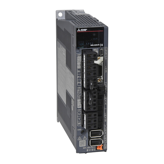
1. FUNCTIONS AND CONFIGURATION 1.7 Structure 1.7.1 Parts identification (1) 200 V class "MR-J4-_B_" means "MR-J4-_B_(-RJ) Servo Amplifier Instruction Manual". (a) MR-J4-200B-RJ010 or less "MR-J4-_B_" means "MR-J4-_B_(-RJ) Servo Amplifier Instruction Manual". Name/Application Detailed explanation Display The 3-digit, seven-segment LED shows the servo status and the alarm number. - Page 27 1. FUNCTIONS AND CONFIGURATION (b) MR-J4-350B-RJ010 Name/Application Detailed explanation The broken line area is the same as Main circuit power supply connector (CNP1) MR-J4-_B_ section 3.1 MR-J4-200B-RJ010 or less. Connect the input power supply. MR-J4-_B_ section 3.3 Rating plate Section 1.6 Servo motor power supply connector (CNP3) Connect the servo motor.
- Page 28 1. FUNCTIONS AND CONFIGURATION (c) MR-J4-500B-RJ010 POINT The servo amplifier is shown with the front cover open. The front cover cannot be removed. Name/Application Detailed explanation The broken line area is the same as Control circuit terminal block (TE2) MR-J4-200B-RJ010 or less. Used to connect the control circuit power supply.
- Page 29 1. FUNCTIONS AND CONFIGURATION (d) MR-J4-700B-RJ010 POINT The servo amplifier is shown without the front cover. For removal of the front cover, refer to section 1.7.2 of "MR-J4-_B_(-RJ) Servo Amplifier Instruction Manual". Name/Application Detailed explanation The broken line area is the same as Power factor improving reactor terminal block (TE3) MR-J4-200B-RJ010 or less.
- Page 30 1. FUNCTIONS AND CONFIGURATION (e) MR-J4-11KB-RJ010/MR-J4-15KB-RJ010 POINT The servo amplifier is shown without the front cover. For removal of the front cover, refer to section 1.7.2 of "MR-J4-_B_(-RJ) Servo Amplifier Instruction Manual". Name/Application Detailed explanation The broken line area is the same as Power factor improving reactor terminal block (TE1-2) MR-J4-200B-RJ010 or less.
- Page 31 1. FUNCTIONS AND CONFIGURATION (f) MR-J4-22KB-RJ010 POINT The servo amplifier is shown without the front cover. For removal of the front cover, refer to section 1.7.2 of "MR-J4-_B_(-RJ) Servo Amplifier Instruction Manual". Name/Application Detailed explanation The broken line area is the same as Power factor improving reactor terminal block (TE1-2) MR-J4-200B-RJ010 or less.
- Page 32 1. FUNCTIONS AND CONFIGURATION (2) 400 V class (a) MR-J4-200B4-RJ010 or less Name/Application Detailed explanation Display The 3-digit, 7-segment LED shows the servo status and the alarm number. Axis selection rotary switch (SW1) MR-J4-_B_ section Used to set the axis No. of servo amplifier. Control axis setting switch (SW2) The test operation switch, the control axis deactivation setting switch, and the auxiliary axis number setting...
- Page 33 1. FUNCTIONS AND CONFIGURATION (b) MR-J4-350B4-RJ010 Name/Application Detailed explanation The broken line area is the same as Main circuit power connector (CNP1) MR-J4-_B_ section MR-J4-200B4-RJ010 or less. Connect the input power supply. MR-J4-_B_ section Rating plate Section 1.6 Control circuit power connector (CNP2) MR-J4-_B_ section Connect the control circuit power supply and regenerative option.
- Page 34 1. FUNCTIONS AND CONFIGURATION (c) MR-J4-500B4-RJ010 POINT The servo amplifier is shown without the front cover. For removal of the front cover, refer to section 1.7.2 of "MR-J4-_B_(-RJ) Servo Amplifier Instruction Manual". Name/Application Detailed explanation The broken line area is the same as Control circuit terminal block (TE2) MR-J4-_B_ section MR-J4-200B4-RJ010 or less.
- Page 35 1. FUNCTIONS AND CONFIGURATION (d) MR-J4-700B4-RJ010 POINT The servo amplifier is shown without the front cover. For removal of the front cover, refer to section 1.7.2 of "MR-J4-_B_(-RJ) Servo Amplifier Instruction Manual". Name/Application Detailed explanation The broken line area is the same as Power factor improving reactor terminal block (TE3) MR-J4-200B4-RJ010 or less.
- Page 36 1. FUNCTIONS AND CONFIGURATION (e) MR-J4-11KB4-RJ010/MR-J4-15KB4-RJ010 POINT The servo amplifier is shown without the front cover. For removal of the front cover, refer to section 1.7.2 of "MR-J4-_B_(-RJ) Servo Amplifier Instruction Manual". Name/Application Detailed explanation The broken line area is the same as Power factor improving reactor terminal block (TE1-2) MR-J4-200B4-RJ010 or less.
- Page 37 1. FUNCTIONS AND CONFIGURATION (f) MR-J4-22KB4-RJ010 POINT The servo amplifier is shown without the front cover. For removal of the front cover, refer to section 1.7.2 of "MR-J4-_B_(-RJ) Servo Amplifier Instruction Manual". Name/Application Detailed explanation The broken line area is the same as Power factor improving reactor terminal block (TE1-2) MR-J4-200B4-RJ010 or less.
-
Page 38: Parts Identification Of Mr-J3-T10
1. FUNCTIONS AND CONFIGURATION 1.7.2 Parts identification of MR-J3-T10 Name/Application Detailed explanation Display MR-J3-T10 D LINK Status of CC-Link IE communication is displayed. Section 4.3 ERR. ERR. L ERR. D LINK Display LINK Status of CC-Link IE communication is L.ERR displayed. -
Page 39: Installation And Removal Of Mr-J3-T10
1. FUNCTIONS AND CONFIGURATION 1.8 Installation and removal of MR-J3-T10 Before installing or removing the CC-Link IE interface unit, turn off the power and wait for 15 minutes or more until the charge lamp turns off. Then, confirm that the WARNING voltage between P+ and N- is safe with a voltage tester and others. - Page 40 1. FUNCTIONS AND CONFIGURATION (1) MR-J4-350B-RJ010 or smaller capacity models POINT Do not remove the cover of the CN9 connector because the connector is not used. (a) Installation of MR-J3-T10 1) Remove the cover of connector for connecting an option. Guide hole Make sure to store the removed cover.
- Page 41 1. FUNCTIONS AND CONFIGURATION (2) MR-J4-350B-RJ010/MR-J4-500B-RJ010/MR-J4-700B-RJ010 (a) Removal of the side cover 1) Keep pushing the knobs ( a) , b) ) and pull out the side cover to the arrow direction. (b) Installation of MR-J3-T10 1) Find the guide hole on the side of the servo amplifier. To the guide hole, insert the MR-J3-T10's guide pins.
- Page 42 1. FUNCTIONS AND CONFIGURATION (d) Installation of the side cover 1) Insert the side cover setting tabs into the sockets a) of servo amplifier. Side cover setting tab 2) Push the side cover at the supporting point a) until the knobs click.
-
Page 43: Configuration Including Peripheral Equipment
1. FUNCTIONS AND CONFIGURATION 1.9 Configuration including peripheral equipment Connecting a servo motor for different axis to U, V, W, or CN2 of the servo CAUTION amplifier may cause a malfunction. POINT Equipment other than the servo amplifier and servo motor are optional or recommended products. - Page 44 1. FUNCTIONS AND CONFIGURATION (2) MR-J4-350B-RJ010 R S T (Note 2) Power supply Molded-case circuit breaker Personal (MCCB) computer MR Configurator2 Servo amplifier MR-J3-T10 (Note 3) Magnetic contactor (MC) (Note 1) Junction terminal block Line noise filter To safety relay or MR-J3-D05 (FR-BSF01) safety logic unit CN10A...
- Page 45 1. FUNCTIONS AND CONFIGURATION (3) MR-J4-500B-RJ010 R S T (Note 2) Power supply Molded-case Personal circuit breaker computer (MCCB) MR Configurator2 Servo amplifier MR-J3-T10 (Note 3) Magnetic contactor (MC) (Note 1) Junction terminal block Line noise To safety relay or MR-J3-D05 filter safety logic unit (FR-BLF)
- Page 46 1. FUNCTIONS AND CONFIGURATION (4) MR-J4-700B-RJ010 R S T (Note 2) Power supply Personal computer Molded-case MR Configurator2 circuit breaker (MCCB) Servo amplifier MR-J3-T10 (Note 3) Magnetic contactor (MC) Junction terminal block (Note 1) To safety relay or MR-J3-D05 safety logic unit Line noise filter CN10A...
- Page 47 1. FUNCTIONS AND CONFIGURATION (5) MR-J4-11KB-RJ010/MR-J4-15KB-RJ010 Personal computer MR Configurator2 R S T (Note 2) Power supply Molded-case circuit breaker (MCCB) Junction terminal block (Note 3) Magnetic To safety relay or MR-J3-D05 contactor safety logic unit (MC) (Note 1) CN10A CC-Link IE Field Network Line noise...
- Page 48 1. FUNCTIONS AND CONFIGURATION (6) MR-J4-22KB-RJ010 R S T (Note 2) Power supply Personal computer Molded-case MR Configurator2 circuit breaker (MCCB) (Note 3) Magnetic contactor (MC) Junction terminal block (Note 1) To safety relay or MR-J3-D05 safety logic unit Line noise filter (FR-BLF) CN10A...
-
Page 49: Class
1. FUNCTIONS AND CONFIGURATION 1.9.2 400 V class (1) MR-J4-200B4-RJ010 or less R S T (Note 2) Power supply Molded-case Personal circuit breaker computer (MCCB) MR Configurator2 (Note 3) Magnetic contactor (MC) (Note 1) Junction terminal block Line noise filter To safety relay or MR-J3-D05 (FR-BSF01) safety logic unit... - Page 50 1. FUNCTIONS AND CONFIGURATION (2) MR-J4-350B4-RJ010 R S T (Note 2) Power supply Molded-case Personal circuit breaker computer (MCCB) MR Configurator2 (Note 3) Magnetic contactor (MC) (Note 1) Junction terminal block Line noise filter To safety relay or MR-J3-D05 (FR-BSF01) safety logic unit CN10A CC-Link IE...
- Page 51 1. FUNCTIONS AND CONFIGURATION (3) MR-J4-500B4-RJ010 R S T (Note 2) Power supply Personal computer Molded-case MR Configurator2 circuit breaker (MCCB) (Note 3) Magnetic contactor (MC) Junction terminal block (Note 1) Power factor improving DC reactor To safety relay or MR-J3-D05 (FR-HEL-H) safety logic unit Line noise...
- Page 52 1. FUNCTIONS AND CONFIGURATION (4) MR-J4-700B4-RJ010 Personal computer R S T MR Configurator2 (Note 2) Power supply Molded-case circuit breaker (MCCB) (Note 3) Junction terminal block Magnetic contactor (MC) To safety relay or MR-J3-D05 (Note 1) safety logic unit CN10A CC-Link IE Field Network Line noise...
- Page 53 1. FUNCTIONS AND CONFIGURATION (5) MR-J4-11KB4-RJ010/MR-J4-15KB4-RJ010 Personal computer MR Configurator2 R S T (Note 2) Power supply Molded-case circuit breaker (MCCB) Junction terminal block (Note 3) Magnetic To safety relay or MR-J3-D05 contactor safety logic unit (MC) (Note 1) CN10A CC-Link IE Field Network Line noise...
- Page 54 1. FUNCTIONS AND CONFIGURATION (6) MR-J4-22KB4-RJ010 R S T (Note 2) Power supply Personal computer Molded-case MR Configurator2 circuit breaker (MCCB) (Note 3) Magnetic contactor (MC) Junction terminal block (Note 1) To safety relay or MR-J3-D05 safety logic unit Line noise filter (FR-BLF) CN10A...
- Page 55 1. FUNCTIONS AND CONFIGURATION MEMO 1 - 44...
-
Page 56: Installation
2. INSTALLATION 2. INSTALLATION WARNING To prevent electric shock, ground each equipment securely. Stacking in excess of the specified number of product packages is not allowed. Install the equipment on incombustible material. Installing it directly or close to combustibles will lead to a fire. Install the servo amplifier and the servo motor in a load-bearing place in accordance with the Instruction Manual. -
Page 57: Installation Direction And Clearances
2. INSTALLATION 2.1 Installation direction and clearances The equipment must be installed in the specified direction. Otherwise, it may cause a malfunction. CAUTION Leave specified clearances between the servo amplifier/MR-J3-T10 and the cabinet walls or other equipment. Otherwise, it may cause a malfunction. (1) Installation clearances of the servo amplifier (a) Installation of one servo amplifier Cabinet... - Page 58 2. INSTALLATION (b) Installation of two or more servo amplifiers POINT Close mounting is possible depending on the capacity of the servo amplifier. Refer to section 1.3.1 for availability of close mounting. When mounting the servo amplifiers closely, do not install the servo amplifier whose depth is larger than that of the left side servo amplifier since CNP1, CNP2, and CNP3 connectors cannot be disconnected.
-
Page 59: Keep Out Foreign Materials
2. INSTALLATION 2.2 Keep out foreign materials (1) When drilling in the cabinet, prevent drill chips and wire fragments from entering the servo amplifier. (2) Prevent oil, water, metallic dust, etc. from entering the servo amplifier through openings in the cabinet or a cooling fan installed on the ceiling. -
Page 60: Signals And Wiring
3. SIGNALS AND WIRING 3. SIGNALS AND WIRING Any person who is involved in wiring should be fully competent to do the work. Before wiring, turn off the power and wait for 15 minutes or more until the charge lamp turns off. Then, confirm that the voltage between P+ and N- is safe with a voltage tester and others. - Page 61 3. SIGNALS AND WIRING Connect the servo amplifier power output (U, V, and W) to the servo motor power input (U, V, and W) directly. Do not let a magnetic contactor, etc. intervene. Otherwise, it may cause a malfunction. Servo amplifier Servo motor Servo amplifier Servo motor...
-
Page 62: I/O Signal Connection Example
Be sure to mount a data line filter to the CC-Link IE Field Network cable. For the branch of CC-Link IE Field Network by the switching hub, use DT135TX (Mitsubishi Electric System & Service Co., Ltd.). For details of the switching hub, refer to "MELSEC-Q QD77GF Simple Motion Module User's Manual (Positioning Control)". - Page 63 3. SIGNALS AND WIRING Note 1. To prevent an electric shock, always connect the protective earth (PE) terminal (marked ) of the servo amplifier to the protective earth (PE) of the cabinet. 2. Connect the diode in the correct direction. If it is connected reversely, the servo amplifier will malfunction and will not output signals, disabling EM2 (Forced stop 2) and other protective circuits.
-
Page 64: For Source I/O Interface
3. SIGNALS AND WIRING 3.1.2 For source I/O interface POINT For notes, refer to section 3.1.1. Servo amplifier 10 m or shorter (Note 9) 10 m or shorter (Note 12) (Note 9) (Note 7) 24 V DC Main circuit power supply (Note 3, 4) DOCOM Forced stop 2... -
Page 65: Servo Motor With An Electromagnetic Brake
3. SIGNALS AND WIRING 3.2 Servo motor with an electromagnetic brake 3.2.1 Safety precautions Configure an electromagnetic brake circuit so that it is activated also by an external EMG stop switch. Contacts must be opened when ALM Contacts must be opened (Malfunction) or MBR (Electromagnetic with the EMG stop switch. -
Page 66: Timing Chart
3. SIGNALS AND WIRING 3.2.2 Timing chart (1) When you use the forced stop deceleration function POINT To enable the function, set "2 _ _ _ (initial value)" in [Pr. PA04]. (a) At power-on to ready-off from the controller Main circuit power supply Control circuit Initialization... - Page 67 3. SIGNALS AND WIRING (b) Servo-on command on/off When servo-on command is turned off, the servo lock will be released after Tb [ms], and the servo motor will coast. If the electromagnetic brake is enabled during servo-lock, the brake life may be shorter.
- Page 68 3. SIGNALS AND WIRING POINT To enable the function, set "2 _ _ _ (initial value)" in [Pr. PA04]. (c) Forced stop 2 on/off ON (disabled) EM2 (Forced stop 2) OFF (enabled) Controlword (4) Enable operation (Controller → Servo amplifier) Servo-on command on Statusword (E) Operation enabled (F) Quick stop active...
- Page 69 3. SIGNALS AND WIRING (d) Alarm occurrence 1) When the forced stop deceleration function is enabled Alarm occurrence Alarm reset ON (disabled) EM2 (Forced stop 2) OFF (enabled) (15) Fault Reset Controlword (4) Enable operation (4) Enable operation (Controller → Servo amplifier) Servo-on command on Servo-on command on (B) Switched on...
- Page 70 3. SIGNALS AND WIRING 2) When the forced stop deceleration function is disabled Alarm occurrence ON (disabled) EM2 (Forced stop 2) OFF (enabled) Controlword (4) Enable operation (Controller → Servo amplifier) Servo-on command on (G) Fault reaction active Statusword (E) Operation enabled (H) Fault (Servo amplifier →...
- Page 71 3. SIGNALS AND WIRING 3) When CC-Link IE Field communication brake occurred Communication broke Communication recovered (unexpected parallel off) (parallel on) (Note 5) ON (disabled) EM2 (Forced stop 2) OFF (enabled) (4) Enable operation Servo-on command on Controlword Initial value (4) Enable operation (Controller →...
- Page 72 3. SIGNALS AND WIRING (c) Both main and control circuit power supplies off Main circuit, Control circuit power Main circuit power supply Control circuit ON (disabled) EM2 (Forced stop 2) OFF (enabled) (4) Enable operation Servo-on command on Controlword (Controller → Servo amplifier) Statusword (E) Operation (Servo amplifier →...
- Page 73 3. SIGNALS AND WIRING (d) Main circuit power supply off during control circuit power supply on Main circuit power supply Control circuit ON (disabled) EM2 (Forced stop 2) OFF (enabled) Controlword (4) Enable operation (Controller → Servo amplifier) Servo-on command on (G) Fault reaction active Statusword (E) Operation...
- Page 74 3. SIGNALS AND WIRING (2) When you do not use the forced stop deceleration function POINT To disable the function, set "0 _ _ _" in [Pr. PA04]. (a) At power-on to ready-off from the controller It is the same as (1) (a) of this section. (b) Servo-on command on/off It is the same as (1) (b) of this section.
- Page 75 3. SIGNALS AND WIRING 2) When CC-Link IE Field communication brake occurred Communication broke Communication recovered (unexpected parallel off) (parallel on) (Note 3) ON (disabled) EM2 (Forced stop 2) OFF (enabled) Controlword (4) Enable operation Initial value (4) Enable operation (Controller →...
- Page 76 3. SIGNALS AND WIRING (f) Main circuit power supply off during control circuit power supply on Main circuit power supply Forced stop command ON (disabled) (Controller → Servo amplifier) OFF (enabled) EM2 (Forced stop 2) Controlword (4) Enable operation (Controller → Servo amplifier) Servo-on command on (G) Fault reaction active Statusword...
- Page 77 3. SIGNALS AND WIRING MEMO 3 - 18...
-
Page 78: Startup
4. STARTUP 4. STARTUP Do not operate the switches with wet hands. Otherwise, it may cause an electric WARNING shock. Before starting operation, check the parameters. Improper settings may cause some machines to operate unexpectedly. The servo amplifier heat sink, regenerative resistor, servo motor, etc. may be hot CAUTION while power is on or for some time after power-off. -
Page 79: Switching Power On For The First Time
4. STARTUP 4.1 Switching power on for the first time When switching power on for the first time, follow this section to make a startup. 4.1.1 Startup procedure Wiring check Check whether the servo amplifier and servo motor are wired correctly using visual inspection, DO forced output function ("MR-J4-_B_(-RJ) Servo Amplifier Instruction Manual"... -
Page 80: Wiring Check
4. STARTUP 4.1.2 Wiring check (1) Power supply system wiring Before switching on the main circuit and control circuit power supplies, check the following items. (a) Power supply system wiring The power supplied to the power input terminals (L1, L2, L3, L11, and L21) of the servo amplifier should satisfy the defined specifications. - Page 81 4. STARTUP b) When you use a regenerative option for 7 kW or more servo amplifiers For 7 kW servo amplifiers, the lead wire of the built-in regenerative resistor connected to P+ terminal and C terminal should not be connected. The regenerative option should be connected to P+ terminal and C terminal.
- Page 82 4. STARTUP c) When you use a brake unit and power regeneration converter for 5 kW or more servo amplifiers For 5 kW or 7 kW servo amplifiers, the lead wire of built-in regenerative resistor connected to P+ terminal and C terminal should not be connected. Brake unit, power regeneration converter should be connected to P+ terminal and N- terminal.
-
Page 83: Surrounding Environment
4. STARTUP 4.1.3 Surrounding environment (1) Cable routing (a) The wiring cables should not be stressed. (b) The encoder cable should not be used in excess of its bending life. (Refer to "MR-J4-_B_(-RJ) Servo Amplifier Instruction Manual" section 10.4.) (c) The connector of the servo motor should not be stressed. (2) Environment Signal cables and power cables are not shorted by wire offcuts, metallic dust or the like. - Page 84 4. STARTUP (1) Test operation select switch (SW2-1) To use the test operation mode, turn "ON (up)" the switch. Turning "ON (up)" the switch enables the test operation mode. In the test operation mode, the functions such as JOG operation, positioning operation, and machine analyzer are available with MR Configurator2.
- Page 85 4. STARTUP (c) Switch combination list for the station No. setting The following lists show the setting combinations of the auxiliary station number setting switches and station number setting rotary switch. Station Station Auxiliary station number Auxiliary station number Station No. Station No.
-
Page 86: Scrolling Display
4. STARTUP 4.2.2 Scrolling display (1) Normal display When there is no alarm, the station No. and blank are displayed in rotation. After 1.6 s Status Blank After 0.2 s Status Station No. (1 digit) (2 digits) "b": Indicates ready-off and servo-off status. "C": Indicates ready-on and servo-off status. -
Page 87: Status Display Of A Station
4. STARTUP 4.2.3 Status display of a station (1) Display sequence Servo amplifier power on System check in progress Waiting for controller power-on (CC-Link IE communication) Controller power on (CC-Link IE communication starts) Initial data communication with the servo system controller (initialization communication) When an alarm No. - Page 88 4. STARTUP (2) Indication list Display Status Description Initializing System check in progress The servo amplifier power was switched on when the controller power was off. The station Nos. set to the auxiliary station number setting switches (SW2-3 and SW2-4) and the station number setting rotary switch (SW1) do not match the one set to the servo system controller.
-
Page 89: Display Of Mr-J3-T10 Cc-Link Ie Field Network Interface Unit
4. STARTUP 4.3 Display of MR-J3-T10 CC-Link IE Field Network interface unit The table below shows the detailed description of the communication alarm display area. MR-J3-T10 has eight kinds of LED indication. Table 4.1 LED indication list MR-J3-T10 Name Description status Operation status Operating normally (RUN status) -
Page 90: Parameters
5. PARAMETERS 5. PARAMETERS Never make a drastic adjustment or change to the parameter values as doing so will make the operation unstable. CAUTION If fixed values are written in the digits of a parameter, do not change these values. Do not change parameters for manufacturer setting. - Page 91 5. PARAMETERS 5.1.1 Basic setting parameters ([Pr. PA_ _ ]) Initial Symbol Name Unit value PA01 For manufacturer setting 1000h PA02 **REG Regenerative option 0000h PA03 *ABS Absolute position detection system 0000h PA04 *AOP1 Function selection A-1 2000h PA05 For manufacturer setting 10000 PA06 PA07...
-
Page 92: Gain/Filter Setting Parameters ([Pr. Pb_ _ ])
5. PARAMETERS 5.1.2 Gain/filter setting parameters ([Pr. PB_ _ ]) Initial Symbol Name Unit value PB01 FILT Adaptive tuning mode (adaptive filter II) 0000h PB02 VRFT Vibration suppression control tuning mode (advanced vibration suppression control II) 0000h PB03 For manufacturer setting 18000 PB04 Feed forward gain... -
Page 93: Extension Setting Parameters ([Pr. Pc_ _ ])
5. PARAMETERS Initial Symbol Name Unit value PB54 VRF23 Vibration suppression control 2 - Vibration frequency damping 0.00 PB55 VRF24 Vibration suppression control 2 - Resonance frequency damping 0.00 PB56 For manufacturer setting PB57 PB58 0.00 PB59 0.00 PB60 PB61 PB62 0000h PB63... -
Page 94: I/O Setting Parameters ([Pr. Pd_ _ ])
5. PARAMETERS Initial Symbol Name Unit value PC41 For manufacturer setting 0000h PC42 0000h PC43 0000h PC44 0000h PC45 0000h PC46 0000h PC47 0000h PC48 0000h PC49 0000h PC50 0000h PC51 0000h PC52 0000h PC53 0000h PC54 0000h PC55 0000h PC56 0000h PC57... -
Page 95: Extension Setting 2 Parameters ([Pr. Pe_ _ ])
5. PARAMETERS Initial Symbol Name Unit value PD29 For manufacturer setting 0000h PD30 PD31 PD32 PD33 0000h PD34 0000h PD35 0000h PD36 0000h PD37 0000h PD38 0000h PD39 0000h PD40 0000h PD41 0000h PD42 0000h PD43 0000h PD44 0000h PD45 0000h PD46 0000h... - Page 96 5. PARAMETERS Initial Symbol Name Unit value PE31 For manufacturer setting 0000h PE32 0000h PE33 0000h PE34 PE35 PE36 PE37 0.00 PE38 0.00 PE39 PE40 0000h PE41 EOP3 Function selection E-3 0000h PE42 For manufacturer setting PE43 PE44 0000h PE45 0000h PE46 0000h...
- Page 97 5. PARAMETERS Initial Symbol Name Unit value PF19 For manufacturer setting 0000h PF20 0000h PF21 Drive recorder switching time setting PF22 For manufacturer setting PF23 OSCL1 Vibration tough drive - Oscillation detection level PF24 *OSCL2 Vibration tough drive function selection 0000h PF25 CVAT...
- Page 98 5. PARAMETERS Initial Symbol Name Unit value Po21 For manufacturer setting 0000h Po22 0000h Po23 0000h Po24 0000h Po25 0000h Po26 0000h Po27 0000h Po28 0000h Po29 0000h Po30 0000h Po31 0000h Po32 0000h 5 - 9...
-
Page 99: Basic Setting Parameters ([Pr. Pa
5. PARAMETERS 5.2 Detailed list of parameters POINT "x" in the "Setting digit" columns means which digit to set a value. 5.2.1 Basic setting parameters ([Pr. PA_ _ ]) Initial Setting Symbol Name and function value range [unit] PA02 **REG Regenerative option Refer to Name and function... - Page 100 5. PARAMETERS Initial Setting Symbol Name and function value range [unit] PA03 *ABS Absolute position detection system Refer to Name and function Set this parameter when using the absolute position detection system. The parameter is not column. available in the speed control mode and torque control mode. Setting Initial Explanation...
- Page 101 5. PARAMETERS Initial Setting Symbol Name and function value range [unit] PA08 Auto tuning mode Refer to Name and function Select the gain adjustment mode. column. Setting Initial Explanation digit value _ _ _ x Gain adjustment mode selection 0: 2 gain adjustment mode 1 (interpolation mode) 1: Auto tuning mode 1 2: Auto tuning mode 2 3: Manual mode...
- Page 102 5. PARAMETERS Initial Setting Symbol Name and function value range [unit] PA09 Auto tuning response 1 to 40 Set a response of the auto tuning. Machine characteristic Machine characteristic Setting Setting Guideline for machine Guideline for machine value Response value Response resonance frequency resonance frequency [Hz]...
- Page 103 5. PARAMETERS Initial Setting Symbol Name and function value range [unit] PA15 *ENR Encoder output pulses 4000 Set the encoder output pulses from the servo amplifier by using the number of output pulses [pulse/ 65535 per revolution, dividing ratio, or electronic gear ratio. (after multiplication by 4) rev] To set a numerator of the electronic gear, select "A-phase/B-phase pulse electronic gear setting (_ _ 3 _)"...
- Page 104 5. PARAMETERS Initial Setting Symbol Name and function value range [unit] PA20 *TDS Tough drive setting Refer to Name and function Alarms may not be avoided with the tough drive function depending on the situations of the column. power supply and load fluctuation. You can assign MTTR (During tough drive) to pins CN3-9 to CN3-13 and CN3-15 with [Pr.
- Page 105 5. PARAMETERS Initial Setting Symbol Name and function value range [unit] PA23 DRAT Drive recorder arbitrary alarm trigger setting Refer to Name and function Setting Initial column. Explanation digit value _ _ x x Alarm detail No. setting Set the digits when you execute the trigger with arbitrary alarm detail No.
-
Page 106: Gain/Filter Setting Parameters ([Pr. Pb
5. PARAMETERS 5.2.2 Gain/filter setting parameters ([Pr. PB_ _ ]) Initial Setting Symbol Name and function value range [unit] PB01 FILT Adaptive tuning mode (adaptive filter II) Refer to Name and function Set the adaptive filter tuning. column. Setting Initial Explanation digit value... - Page 107 5. PARAMETERS Initial Setting Symbol Name and function value range [unit] PB07 Model loop gain 15.0 [rad/s] Set the response gain up to the target position. 2000.0 Increasing the setting value will also increase the response level to the position command but will be liable to generate vibration and/or noise.
- Page 108 5. PARAMETERS Initial Setting Symbol Name and function value range [unit] PB14 NHQ1 Notch shape selection 1 Refer to Name and function Set the shape of the machine resonance suppression filter 1. column. When you select "Automatic setting (_ _ _ 1)" of "Filter tuning mode selection" in [Pr. PB01], this parameter will be adjusted automatically.
- Page 109 5. PARAMETERS Initial Setting Symbol Name and function value range [unit] PB17 Shaft resonance suppression filter Refer to Name and function This is used for setting the shaft resonance suppression filter. column. This is used to suppress a low-frequency machine vibration. When you select "Automatic setting (_ _ _ 0)"...
- Page 110 5. PARAMETERS Initial Setting Symbol Name and function value range [unit] PB19 VRF11 Vibration suppression control 1 - Vibration frequency 100.0 Set the vibration frequency for vibration suppression control 1 to suppress low-frequency [Hz] 300.0 machine vibration. When "Vibration suppression control 1 tuning mode selection" is "Automatic setting (_ _ _ 1)" in [Pr.
- Page 111 5. PARAMETERS Initial Setting Symbol Name and function value range [unit] PB45 CNHF Command notch filter Refer to Name and function Set the command notch filter. column. Setting Initial Explanation digit value _ _ x x Command notch filter setting frequency selection Refer to table 5.5 for the relation of setting values to frequency.
- Page 112 5. PARAMETERS Initial Setting Symbol Name and function value range [unit] PB45 CNHF Refer to Name Table 5.6 Notch depth selection and function Setting Depth [dB] Setting Depth [dB] column. -40.0 -6.0 -24.1 -5.0 -18.1 -4.1 -14.5 -3.3 -12.0 -2.5 -10.1 -1.8 -8.5...
- Page 113 5. PARAMETERS Initial Setting Symbol Name and function value range [unit] PB49 NHQ4 Notch shape selection 4 Refer to Name and function Set the shape of the machine resonance suppression filter 4. column. Setting Initial Explanation digit value _ _ _ x Machine resonance suppression filter 4 selection 0: Disabled 1: Enabled...
- Page 114 5. PARAMETERS Initial Setting Symbol Name and function value range [unit] PB53 VRF22 Vibration suppression control 2 - Resonance frequency 100.0 [Hz] Set the resonance frequency for vibration suppression control 2 to suppress low-frequency 300.0 machine vibration. To enable this, select "3 inertia mode (_ _ _ 1)" of "Vibration suppression mode selection" in [Pr.
-
Page 115: Extension Setting Parameters ([Pr. Pc
5. PARAMETERS 5.2.3 Extension setting parameters ([Pr. PC_ _ ]) Initial Setting Symbol Name and function value range [unit] PC01 Error excessive alarm level [rev] Set an error excessive alarm level. (Note) 1000 Set this per rev for rotary servo motors. Setting "0" will be 3 rev. Setting over 200 rev will be clamped with 200 rev. - Page 116 5. PARAMETERS Initial Setting Symbol Name and function value range [unit] PC05 **COP2 Function selection C-2 Refer to Name and function This is used to select the motor-less operation. column. Setting Initial Explanation digit value _ _ _ x Motor-less operation selection 0: Disabled 1: Enabled _ _ x _...
- Page 117 5. PARAMETERS Initial Setting Symbol Name and function value range [unit] PC09 MOD1 Analog monitor 1 output Refer to Name and function Select a signal to output to MO1 (Analog monitor 1). Refer to section 9.1 for detection point of column.
- Page 118 5. PARAMETERS Initial Setting Symbol Name and function value range [unit] PC17 **COP4 Function selection C-4 Refer to Name and function This is used to select a home position setting condition. column. Setting Initial Explanation digit value _ _ _ x Selection of home position setting condition 0: Need to pass servo motor Z-phase after power on 1: Not need to pass servo motor Z-phase after power on...
- Page 119 5. PARAMETERS Initial Setting Symbol Name and function value range [unit] PC24 RSBR Forced stop deceleration time constant [ms] This is used to set deceleration time constant when you use the forced stop deceleration 20000 function. Set the time per ms from the rated speed to 0 r/min. Dynamic brake Rated speed Forced stop deceleration...
-
Page 120: I/O Setting Parameters ([Pr. Pd
5. PARAMETERS 5.2.4 I/O setting parameters ([Pr. PD_ _ ]) Initial Setting Symbol Name and function value range [unit] PD02 *DIA2 Input signal automatic on selection 2 Refer to Name and function When disabling (releasing) FLS and RLS with this parameter, preset "Upper limit" and "Lower column. - Page 121 5. PARAMETERS Initial Setting Symbol Name and function value range [unit] PD08 *DO2 Output device selection 2 Refer to Name and function You can assign any output device to the CN3-9 pin. INP (In-position) is assigned as the initial column. value.
-
Page 122: Extension Setting 2 Parameters ([Pr. Pe
5. PARAMETERS Initial Setting Symbol Name and function value range [unit] PD14 *DOP3 Function selection D-3 Refer to Name and function Setting Initial column. Explanation digit value _ _ _ x For manufacturer setting _ _ x _ Selection of output device at warning occurrence Select WNG (Warning) and ALM (Malfunction) output status at warning occurrence. -
Page 123: Extension Setting 3 Parameters ([Pr. Pf
5. PARAMETERS 5.2.6 Extension setting 3 parameters ([Pr. PF_ _ ]) Initial Setting Symbol Name and function value range [unit] PF06 *FOP5 Function selection F-5 Refer to Name and function Setting Initial column. Explanation digit value _ _ _ x Electronic dynamic brake selection 0: Automatic (enabled only for specified servo motors) 2: Disabled... - Page 124 5. PARAMETERS Initial Setting Symbol Name and function value range [unit] PF25 CVAT SEMI-F47 function - Instantaneous power failure detection time [ms] Set the time of the [AL. 10.1 Voltage drop in the control circuit power] occurrence. To disable the parameter, select "Disabled (_ 0 _ _)" of "SEMI-F47 function selection" in [Pr. PA20].
-
Page 125: Option Setting Parameters
5. PARAMETERS 5.2.7 Option setting parameters ([Pr. Po_ _) Initial Setting Symbol Name and function value range [unit] Po02 *STNO CC-Link IE communication station number selection 0 to 120 Use this parameter to set a station No. of the servo amplifier. Station Nos. -
Page 126: Troubleshooting
6. TROUBLESHOOTING 6. TROUBLESHOOTING POINT Refer to "MELSERVO-J4 Servo Amplifier Instruction Manual (Troubleshooting)" for details of alarms and warnings. As soon as an alarm occurs, make the Servo-off status and interrupt the main circuit power. [AL. 37 Parameter error] and warnings are not recorded in the alarm history. 6.1 Alarm and warning list When an error occurs during operation, the corresponding alarm or warning is displayed. - Page 127 6. TROUBLESHOOTING Alarm reset Stop Detail method Name Detail name (Note 3, Encoder initial communication - Receive data 16.1 error 1 Encoder initial communication - Receive data 16.2 error 2 Encoder initial communication - Receive data 16.3 error 3 Encoder initial communication - Transmission 16.5 data error 1 Encoder initial communication - Transmission...
- Page 128 6. TROUBLESHOOTING Alarm reset Stop Detail method Name Detail name (Note 3, 30.1 Regeneration heat error (Note 1) (Note 1) (Note 1) Regenerative error 30.2 Regeneration signal error (Note 1) (Note 1) (Note 1) (Note 1) 30.3 Regeneration feedback signal error (Note 1) (Note 1) (Note 1) Overspeed 31.1...
- Page 129 6. TROUBLESHOOTING Alarm reset Stop Detail method Name Detail name (Note 3, 75.3 Option card connection error Option card error 2 75.4 Option card disconnected USB communication time- 8A.1 USB communication time-out error out error 8D.1 CC-Link IE communication error 1 8D.2 CC-Link IE communication error 2 8D.3...
- Page 130 6. TROUBLESHOOTING Stop method Detail Name Detail name (Note 2, Servo amplifier overheat 91.1 Main circuit device overheat warning warning (Note 1) 92.1 Encoder battery cable disconnection warning Battery cable disconnection warning 92.3 Battery degradation 95.1 STO1 off detection STO warning 95.2 STO2 off detection Home position setting...
-
Page 131: Troubleshooting At Power On
6. TROUBLESHOOTING 6.2 Troubleshooting at power on When an error occurs at the power supply of the controller or servo amplifier, improper boot of the servo amplifier might be the cause. Check the display of the servo amplifier, and take actions according to this section. - Page 132 6. TROUBLESHOOTING Display Description Cause Checkpoint Action The synchronous MR-J3-T10 is "AC" is displayed in the Replace the MR-J3-T10. communications by malfunctioning. corresponding station and specified cycle could not following stations. be made. The servo amplifier is "AC" is displayed in the Replace the servo amplifier.
- Page 133 6. TROUBLESHOOTING MEMO 6 - 8...
-
Page 134: Dimensions
7. DIMENSIONS 7. DIMENSIONS The following item is the same as MR-J4-_B_ servo amplifiers. For details of the items, refer to each chapter/section of the detailed description field. "MR-J4-_B_" means "MR-J4-_B_(-RJ) Servo Amplifier Instruction Manual". Item Detailed explanation Connector MR-J4-_B_ section 9.2 7 - 1... -
Page 135: Servo Amplifier
7. DIMENSIONS 7.1 Servo amplifier 7.1.1 200 V class (1) MR-J4-10B-RJ010/MR-J4-20B-RJ010 [Unit: mm] φ6 mounting hole Lock knob Approx. 80 CNP1 CNP2 CNP3 Approx. 69.3 Approx. 38.5 MR-BAT6V1SET is mounted Mass: 0.8 [kg] (servo amplifier only) Mounting screw Terminal Screw size: M5 CNP1 Tightening torque: 3.24 [N•m] Approx. - Page 136 7. DIMENSIONS (2) MR-J4-40B-RJ010/MR-J4-60B-RJ010 [Unit: mm] φ6 mounting hole Approx. 80 Lock knob CNP1 CNP2 CNP3 Approx. 69.3 MR-BAT6V1SET Approx. 38.5 is mounted Mass: 1.0 [kg] (servo amplifier only) Mounting screw Terminal Screw size: M5 CNP1 Tightening torque: 3.24 [N•m] Approx.
- Page 137 7. DIMENSIONS (3) MR-J4-70B-RJ010/MR-J4-100B-RJ010 [Unit: mm] φ6 mounting hole Lock knob Approx. 80 Exhaust CNP1 CNP2 CNP3 Cooling fan intake Approx. 69.3 MR-BAT6V1SET Approx. 38.5 is mounted Mass: 1.4 [kg] (servo amplifier only) Mounting screw Terminal Screw size: M5 CNP1 Tightening torque: 3.24 [N•m] Approx.
- Page 138 7. DIMENSIONS (4) MR-J4-200B-RJ010 [Unit: mm] φ6 mounting hole Approx. 80 Lock knob Exhaust CNP1 CNP2 CNP3 Approx. 69.3 Cooling fan intake Approx. 38.5 MR-BAT6V1SET is mounted Mass: 2.1 [kg] (servo amplifier only) Mounting screw Terminal Screw size: M5 CNP1 Tightening torque: 3.24 [N•m] Approx.
- Page 139 7. DIMENSIONS (5) MR-J4-350B-RJ010 [Unit: mm] Mounting hole Approx. 80 Lock knob Exhaust CNP1 CNP3 CNP2 Approx. 69.3 Cooling fan intake Approx. 38.5 MR-BAT6V1SET is mounted Mass: 2.3 [kg] (servo amplifier only) Mounting screw Terminal Screw size: M5 CNP1 Tightening torque: 3.24 [N•m] Approx.
- Page 140 7. DIMENSIONS (6) MR-J4-500B-RJ010 [Unit: mm] Approx. 25 Approx. 80 2-φ6 mounting hole Approx. 28 Cooling fan exhaust MR-BAT6V1SET is mounted Air intake Mass: 4.0 [kg] (servo amplifier only) Mounting screw Terminal Screw size: M5 Screw size: M3.5 Tightening torque: 3.24 [N•m] Tightening torque: 0.8 [N•m] Approx.
- Page 141 7. DIMENSIONS (7) MR-J4-700B-RJ010 [Unit: mm] Approx. 80 2-φ6 mounting hole Approx. 28 Cooling fan exhaust MR-BAT6V1SET is mounted Air intake Built-in regenerative resistor lead terminal fixing screw Screw size: M4 Tightening torque: 1.2 [N•m] Mass: 6.2 [kg] (servo amplifier only) Mounting screw Terminal Screw size: M5...
- Page 142 7. DIMENSIONS (8) MR-J4-11KB-RJ010/MR-J4-15KB-RJ010 [Unit: mm] Approx. 80 2-φ6 mounting hole Approx. 28 10.5 Cooling fan exhaust 24.2 TE1-1 TE1-2 With MR-BAT6V1SET 25.5 Intake 224.2 57.9 237.4 5 × 25.5 (= 127.5) Mass: 13.4 [kg] (servo amplifier only) Mounting screw Terminal Screw size: M5 TE1-1...
- Page 143 7. DIMENSIONS (9) MR-J4-22KB-RJ010 [Unit: mm] Approx. 80 Approx. 28 2-φ6 mounting hole Cooling fan exhaust With MR-BAT6V1SET TE1-1 32.7 TE1-2 25.5 188.5 Intake 59.9 223.4 235.4 5 × 25.5 (= 127.5) Mass: 18.2 [kg] (servo amplifier only) Mounting screw Terminal Screw size: M10 TE1-1...
-
Page 144: Class
7. DIMENSIONS 7.1.2 400 V class (1) MR-J4-60B4-RJ010/MR-J4-100B4-RJ010 [Unit: mm] Approx. 80 φ6 mounting hole Lock knob CNP1 CNP2 CNP3 Approx. 69.3 Approx. 38.5 With MR-BAT6V1SET Mass: 1.7 [kg] (servo amplifier only) Mounting screw Terminal CNP1 Screw size: M5 Tightening torque: 3.24 [N•m] Approx. - Page 145 7. DIMENSIONS (2) MR-J4-200B4-RJ010 [Unit: mm] φ6 mounting hole Approx. 80 Lock knob Exhaust CNP1 CNP2 CNP3 Approx. 69.3 Cooling fan intake Approx. 38.5 With MR-BAT6V1SET Mass: 2.1 [kg] (servo amplifier only) Mounting screw Terminal Screw size: M5 CNP1 Tightening torque: 3.24 [N•m] Approx.
- Page 146 7. DIMENSIONS (3) MR-J4-350B4-RJ010 [Unit: mm] 2-φ6 mounting hole Approx. 28 Approx. 80 Approx. 200 94.2 Approx. Cooling fan exhaust CNP1 CNP2 CNP3 With MR-BAT6V1SET Intake Lock knob Mass: 3.6 [kg] (servo amplifier only) Terminal Mounting screw CNP1 Screw size: M5 Tightening torque: 3.24 [N•m] Approx.
- Page 147 7. DIMENSIONS (4) MR-J4-500B4-RJ010 [Unit: mm] 2-φ6 mounting hole Approx. 28 Approx. 80 Approx. 200 Approx. 28 Cooling fan exhaust With MR-BAT6V1SET Intake Built-in regenerative resistor lead terminal fixing screw Screw size: M4 Tightening torque: 1.2 [N•m] Mass: 4.3 [kg] (servo amplifier only) Mounting screw Terminal Screw size: M5...
- Page 148 7. DIMENSIONS (5) MR-J4-700B4-RJ010 [Unit: mm] 2-φ6 mounting hole Approx. 80 Approx. 200 Approx. 28 Approx. 28 Cooling fan exhaust With MR-BAT6V1SET Intake Built-in regenerative resistor lead terminal fixing screw Screw size: M4 Tightening torque: 1.2 [N•m] Mass: 6.5 [kg] (servo amplifier only) Mounting screw Terminal Screw size: M5...
- Page 149 7. DIMENSIONS (6) MR-J4-11KB4-RJ010/MR-J4-15KB4-RJ010 [Unit: mm] Approx. 80 2-φ6 mounting hole Approx. 28 10.5 Cooling fan exhaust 24.2 TE1-1 TE1-2 With MR-BAT6V1SET 25.5 Intake 224.2 57.9 237.4 5 × 25.5 (= 127.5) Mass: 13.4 [kg] (servo amplifier only) Mounting screw Terminal Screw size: M5 TE1-1...
- Page 150 7. DIMENSIONS (7) MR-J4-22KB4-RJ010 [Unit: mm] Approx. 80 Approx. 28 2-φ6 mounting hole Cooling fan exhaust With MR-BAT6V1SET TE1-1 32.7 TE1-2 25.5 188.5 Intake 59.9 223.4 235.4 5 × 25.5 (= 127.5) Mass: 18.2 [kg] (servo amplifier only) Mounting screw Terminal Screw size: M10 TE1-1...
-
Page 151: Mr-J3-T10 Cc-Link Ie Field Network Interface Unit
7. DIMENSIONS 7.2 MR-J3-T10 CC-Link IE Field Network interface unit [Unit: mm] MR-J3-T10 5 × 6 mounting hole for grounding Rating plate Mass: 0.15 [kg] 7 - 18... -
Page 152: Options And Peripheral Equipment
8. OPTIONS AND PERIPHERAL EQUIPMENT 8. OPTIONS AND PERIPHERAL EQUIPMENT Before connecting any option or peripheral equipment, turn off the power and wait for 15 minutes or more until the charge lamp turns off. Then, confirm that the WARNING voltage between P+ and N- is safe with a voltage tester and others. Otherwise, an electric shock may occur. -
Page 153: Combinations Of Cable/Connector Sets
8. OPTIONS AND PERIPHERAL EQUIPMENT 8.1 Combinations of cable/connector sets POINT The CN1A and CN1B connectors are not used. Always put caps came with the servo amplifier. For connecting each servo motor, refer to "Servo Motor Instruction Manual (Vol. 3)". When not using the STO function, attach the short-circuit connector came with the servo amplifier to CN8. - Page 154 8. OPTIONS AND PERIPHERAL EQUIPMENT Product name Model Description Application Servo amplifier Supplied power connector with servo amplifiers of 1 kW or less in 200 For CNP1 For CNP2 For CNP3 V class Connector: Connector: Connector: 06JFAT-SAXGDK-H7.5 05JFAT-SAXGDK-H5.0 03JFAT-SAXGDK-H7.5 (JST) (JST) (JST) Applicable wire size: 0.8 mm...
-
Page 155: Cable For Cc-Link Ie Field Network
A product example on the market is as follows. For the latest product information, contact the manufacturer. Model Manufacturer Contact SC-E5EW(-L) Mitsubishi Electric System & Service email: oss-ip@melsc.jp Co., Ltd. (Note) Note. The SC-E5EW cable is for in-enclosure and indoor uses. The SC-E5EW-L cable is for outdoor use. -
Page 156: Appendix
APPENDIX The following item is the same as MR-J4-_B_ servo amplifiers. For details of the items, refer to each chapter/section of the detailed description field. "MR-J4-_B_" means "MR-J4-_B_(-RJ) Servo Amplifier Instruction Manual". Item Detailed explanation Handling of AC servo amplifier batteries for the MR-J4-_B_ app. - Page 157 APPENDIX (2) Setting The servo amplifier is factory-set to output the servo motor speed to MO1 (Analog monitor 1) and the torque to MO2 (Analog monitor 2). The setting can be changed by setting in [Pr. PC09] and [Pr. PC10] as follows.
- Page 158 APPENDIX Setting Setting Output item Description Output item Description value value Feedback position Bus voltage CCW direction 10 [V] (Note 1, 2, 3) (Note 5) 8 [V] (±10 V/100 Mpulses) 100 [Mpulse] 100 [Mpulse] 400 [V] -10 [V] CW direction Speed command 2 Encoder inside CCW direction...
-
Page 159: App. 3 Special Specification
APPENDIX App. 3 Special specification App. 3.1 Amplifiers without dynamic brake App. 3.1.1 Summary This section explains servo amplifiers without a dynamic brake. The things not explained in this section will be the same as MR-J4-_B_-RJ010. App. 3.1.2 Model The following describes what each block of a model name indicates. Not all combinations of the symbols are available. - Page 160 APPENDIX App. 3.2 Without regenerative resistor App. 3.2.1 Summary This section explains servo amplifiers without a regenerative resistor. The things not explained in this section will be the same as MR-J4-_B_-RJ010. App. 3.2.2 Model The following describes what each block of a model name indicates. Not all combinations of the symbols are available.
- Page 161 This manual confers no industrial property rights or any rights of any other kind, nor does it confer any patent licenses. Mitsubishi Electric Corporation cannot be held responsible for any problems involving industrial property rights which may occur as a result of using the contents noted in this manual.
- Page 162 : +82-2-3660-9510 1480-6, Gayang-Dong, Gangseo-Gu, Seoul, 157-200, Korea : +82-2-3664-8372/8335 Singapore MITSUBISHI ELECTRIC ASIA PTE. LTD. : +65-6473-2308 307 Alexandra Road, Mitsubishi Electric Building, Singapore 159943 : +65-6476-7439 Thailand MITSUBISHI ELECTRIC FACTORY AUTOMATION (THAILAND) : +66-2682-6522 to 31 CO., LTD.
- Page 163 Warranty 1. Warranty period and coverage We will repair any failure or defect hereinafter referred to as "failure" in our FA equipment hereinafter referred to as the "Product" arisen during warranty period at no charge due to causes for which we are responsible through the distributor from which you purchased the Product or our service provider.
- Page 164 MR-J4-B-RJ010 MR-J3-T10 MODEL INSTRUCTION MODEL 1CW810 CODE HEAD OFFICE : TOKYO BLDG MARUNOUCHI TOKYO 100-8310 This Instruction Manual uses recycled paper. SH (NA) 030117-B (1312) MEE Printed in Japan Specifications are subject to change without notice.