
Related Manuals for Sony HXC-FB80


Summary of Contents for Sony HXC-FB80
- Page 1 4-734-401-12 (1) HD Color Camera Operating Instructions Before operating the unit, please read this manual thoroughly and retain it for future reference. HXC-FB80 © 2017 Sony Corporation...
-
Page 2: Table Of Contents
Pin Assignment ...............68 Table of Contents Open Software Licenses............70 Overview ................3 Camera System Components ............ 3 System Configuration ............... 4 Name and Function of Parts..........9 Front and Left Side ..............9 Front and Right Side ...............11 Rear ..................13 Lens (supplied with the HXC-FB80K/HXC-FB80S) .....14 Viewfinder ................15 Connection and Setup ............ -
Page 3: Overview
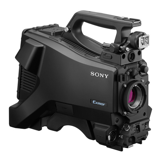
Overview The HXC-FB80 HD Color Camera employs a 2/3-inch type “Exmor” CMOS image sensor that achieves a high sensitivity of F12 (1080/ 59.94i)/F13 (1080/50i) and high S/N ratio of 60 dB. Full HD progressive is also supported at 59.94/50P frame rates. -
Page 4: System Configuration
Peripherals and related devices for the camera are shown in the figures. Note Production of some of the peripherals and related devices shown in the figures may have been discontinued. For advice on choosing devices, please contact your Sony dealer or a Sony service representative. Standalone operation example RCP-1000 series... - Page 5 RCP-1000-series Remote Control Panel a) The maximum transmission distance is 600 m (1,970 ft) when Sony CCFN-25/50/100/150/200/250 Hybrid Fiber Cable is used. b) Operation supported when the signal format is not set to 1080/50P, 59.94P. c) LAN cable connection is supported only for RCP-1500/1501/1530. Power must be supplied via a PoE hub or power supply must be connected to EXT DC IN connector of RCP-1500/1501/1530.
- Page 6 Tripod for portable camera a) The maximum transmission distance is approximately 600 m (1,150 ft) when using Sony CCFN-25/50/100/ 150/200/250 Hybrid Fiber Cable (with camera head + portable lens + HDVF-L750). b) HD TRUNK output supported when the signal format is set to 1080/50i HDR, 59.94i HDR.
- Page 7 Tripod for portable camera a) The maximum transmission distance is approximately 350 m (1,150 ft) when using Sony CCFN-25/50/ 100/150/200/250 Hybrid Fiber Cable (with camera head + portable lens). b) The maximum transmission distance is approximately 10 km (6 miles) when using general-purpose single-mode fiber cables with LC connectors.
- Page 8 RCP-1000 series Remote Control Panel a) The maximum transmission distance is approximately 350 m (1,150 ft) when using Sony CCFN-25/50/100/ 150/200/250 Hybrid Fiber Cable (with camera head + portable lens + HDVF-L750). b) A LAN cable can be used only to connect the RCP-1500/1501/1530. To connect it, power needs to be supplied via a PoE hub or power needs to be supplied to the EXT DC IN connector of the RCP-1500/1501/1530.
-
Page 9: Name And Function Of Parts
Name and Function of Parts Front and Left Side For the pin assignment of each connector, see “Pin Assignment” (page 68). a V-wedge shoe attachment e Cable clamp Attach to a HDVF-L750/HDVF-L770/HDVF-EL75 viewfinder. To Clamp the lens cable and microphone cable. attach a viewfinder, attach the V-wedge shoe here. - Page 10 After locking the lens, be sure to use the lens mount securing rubber Attach a lens. to prevent the lens from becoming detached. Consult your Sony dealer or a Sony service representative for x Lens mount cap information about available lenses.
-
Page 11: Front And Right Side
Front and Right Side Note When connected to a camera control unit or external remote control device • SHUTTER switch (for example, RCP or RM), the following switch functions are controlled • WHT/BLK switch from the connected device. The switches on the camera do not function. •... - Page 12 f RET (return video) button m OUTPUT (output signal select)/AUTO KNEE switch Displays the return video signal in the viewfinder while this button Select the signal that is output from the camera. is pressed. BARS: Output the color bar signal. CAM: Output the video signal being shot.
-
Page 13: Rear
c RET1 (return video 1) button Rear Displays the return video 1 signal in the viewfinder while this button is pressed. For the pin assignment of each connector, see “Pin Assignment” d INTERCOM (intercom volume) knob (page 68). Adjust the intercom volume level. For details about removing the rear cover, see “Removing the rear When connected with the HXCU-FB80, the intercom volume level cover”... -
Page 14: Lens (Supplied With The Hxc-Fb80K/Hxc-Fb80S)
+48V: To supply +48 V phantom power to condenser microphones You can select the input signal to be displayed in the viewfinder on MIC: When a microphone-level input is connected the <EXT RETURN> page in the MAINTENANCE menu. LINE: When a line-level (0 dBu) signal source is connected When connected to a CCU, the connector can be used as an HD PROMPTER output signal connector when set as an output (OUT). -
Page 15: Viewfinder
W (Wide): Wide angle. For details about attaching the HDVF-L10 viewfinder, see T (Telephoto): Telephoto. “Attaching and Adjusting the Viewfinder” (page 18). c Iris operation mode selector switch For details about the viewfinder supplied with the HXC-FB80S, refer A (Auto): The iris is adjusted automatically. to the operation manual for the HDVF-L750. -
Page 16: Connection And Setup
h PEAKING knob Connection and Setup Rotate clockwise to adjust the picture sharpness to make lens focusing easier. This has no effect on the output signal of the camera. i CONTRAST knob Adjust the contrast of the screen. This has no effect on the output signal of the camera. -
Page 17: Ac Power Supply (Standalone Operation)
Operation) Prepare an AC power supply when using the camera in standalone operation mode (without a CCU). For safety, use only the Sony AC adaptor listed below. To AC outlet • AC adaptor: AC-DN10 If using the DC IN connector Connect the AC-DN10 AC adaptor to the DC IN output connector on the camera using an optional DC power cord. -
Page 18: Attaching And Adjusting The Viewfinder
To attach the rear cover 1 Loosen the viewfinder left-to-right positioning ring, 2 Align the guide on the inner side of the rear cover with the camera attach the viewfinder to the viewfinder shoe, and 3 tighten adaptor mount, and insert the cover. the viewfinder left-to-right positioning ring. - Page 19 Adjusting the position Raising the viewfinder barrel or eyepiece To adjust the viewfinder left-to-right position, loosen the left-to- You can view the LCD screen inside the viewfinder or its mirrored right positioning ring. To adjust the front-to-back position, loosen image by raising the viewfinder barrel or eyepiece. the front-to-back positioning lever and lock knob.
- Page 20 To detach the viewfinder barrel Adjusting the diopter Rotate the diopter adjustment ring until the viewfinder image is sharpest. Diopter adjustment ring Adjusting the screen You can adjust the following items. Peaking: Adjust using the PEAKING knob. Contrast: Adjust using the CONTRAST knob. Brightness: Adjust using the BRIGHT knob.
-
Page 21: Attaching The V-Wedge Shoe Attachment
Reduced display mode Attaching the V-Wedge Shoe Displays the camera image at a reduced size, with the tally and other Attachment indicators displayed in the spaces above and below the camera image. To attach the HDVF-L750 Viewfinder supplied with the HXC- Use this mode when the clear visibility of the tally and other FB80S or an optional HDVF-L770/HDVF-EL75, connect the V- indicators is more important. - Page 22 To change the area of use Once the area setting is complete, set the current date and time. Change the setting using COUNTRY on the <OUTPUT FORMAT> Note page in the MAINTENANCE menu. The camera cannot be used if the area of use is not set. Note Setting the area of use The setting is switched to the CCU setting when a CCU is connected.
-
Page 23: Attaching And Adjusting The Lens
<DATE> M14 TOP DATE/TIME Lens mount 2016/04/30 08:32 securing rubber FILE TIMESTAMP FORMAT : 5 M/D/Y Set the date and time items. Rotate the menu control knob to select an item, and press the menu control knob. Rotate the menu control knob to change the setting of the selected item, and press the menu control knob to confirm the setting. -
Page 24: Preparing The Audio Input
The lens supplied with the HXC-FB80K/HXC-FB80S is an aberration correction lens. Contact your Sony dealer or a Sony Connecting a microphone to the AUDIO 1 IN service representative for information about other aberration connector correction lenses. -
Page 25: Mounting On A Tripod
Connect the microphone cable to the AUDIO 1 IN Attaching the microphone holder connector, and secure with the cable clamp. Remove the screw hole cover from the microphone holder attachment. Cable clamp Attach the CAC-12 microphone holder and secure to the Set the audio input 1 selector switch to match the type of camera using the two supplied screws (+B4×8). -
Page 26: Attaching The Shoulder Strap
Place the camera on the tripod adaptor and slide it forward Attaching the Shoulder Strap along the groove of the platform until it clicks into place. Attach an optional shoulder strap (part number: A-6772-374-C) to the camera. Fit one of the clips to the shoulder strap fitting. Pull up the strap to secure it in place. -
Page 27: Adjusting The Shoulder Pad Position
Adjusting the Shoulder Pad Position Shooting You can slide the shoulder pad forward and backward within a 40 mm (1 inch) range. This adjustment helps you get the best balance for shooting with the camera on your shoulder. Basic Procedure for Shooting Lever Turn the camera on. -
Page 28: Adjustments And Settings
In automatic black balance mode, adjustments are performed in the following order: black set and black balance. Manual black balance adjustment can be selected in the menu. For details about manual black balance adjustment, contact a Sony service representative. Set the OUTPUT/AUTO KNEE switch to CAM. - Page 29 The adjustment values are saved automatically in the memory If an error message is displayed, retry the black balance adjustment. selected in step 1 (A or B). If the error message occurs again, consult your Sony dealer or a Sony service representative. Note...
-
Page 30: Setting The Electronic Shutter
For example, if one position is disabled, then that position is not SYSTEM LINE System frequency Shutter speed (Hz) displayed and the button switches between the remaining three 1080 59.94i 60.00 to 4300 positions. 59.94P 59.96 to 4600 Repeat steps 2 and 3 as required. 50.00 to 4700 50.03 to 4600 Assign the CC filter switching function (ELECTRICAL... -
Page 31: Setting Automatic Iris
Repeat this operation until the desired speed is displayed. The TLCS function can be assigned to one of the ASSIGN 1/2/3 To set ECS mode, select “ECS.” To set SLS mode, select buttons, and turned on/off by pressing the button. “SLS.”... -
Page 32: Setting The Camera Outputs
FLICKER: Set the function for flickering the detail signal to 1) Normally, the value is automatically set to the optimum value in conjunction with the AREA MARKER SIZE set value. Use this ON/OFF. (Setting the function to ON makes it easier to setting when an optimum sensitivity value cannot be obtained, check the detail signal on the viewfinder screen.) depending on the shooting environment. -
Page 33: Adjusting The Audio Level
To output as SD-SDI panel connected to the CCU or the CONFIGURATION menu on the CCU. Menu page Page No. Item Setting When the audio input selector switch is set to MIC, the level can be <SDI OUT> SDI OUT SD-SDI adjusted between 20 dB and 60 dB in steps of 10 dB. -
Page 34: Menu Operation
c EX (lens extender) indicator Menu Operation Displayed when using a lens extender. d Zoom position indicator Indicates the approximate position of the zoom lens variator between wide angle (0) and telephoto (99). The menus displayed in the viewfinder enable various settings of the e ! indicator camera. -
Page 35: Operating The Menu
Menu Function 1080-59.94i USER This menu is user defined and can include often-used ASSIGNABLE1 :OFF ASSIGNABLE2 :OFF menu pages selected from among the OPERATION, ASSIGNABLE3 :OFF PAINT, MAINTENANCE, FILE, and DIAGNOSIS ASSIGN CTEMP :5600K menus. The factory default configuration can be changed using the USER MENU CUSTOMIZE !WHITE !5600K... -
Page 36: Selecting A Page
Selecting a Page Setting Menu Items If a ? mark is flashing on the left of the page number, press the menu To select a page from the CONTENTS page control knob to change it to the , pointer. Operation on the Rotate the menu control knob to align the , pointer with the displayed page is enabled. -
Page 37: Editing The User Menu
To return a menu item to the standard value • Changing the order of pages of the USER menu. When an item is selected and the , pointer is displayed, pressing Editing by items and holding the menu control knob for 3 seconds restores the setting value to the state in the reference file. - Page 38 Move the , pointer to the item to be added (this operation Move the , pointer to the position where you wish to move is unnecessary if no item exists on the page, as shown in the the page and press the menu control knob. figure for the previous step), then press the menu control ITEM MOVE knob.
-
Page 39: Hiding The Top Menu Screen
knob until the EDIT PAGE screen appears, then press the To delete, rotate the menu control knob to move the , menu control knob to select the page. pointer to YES and press the menu control knob. EDIT PAGE E00 TOP To change the order of pages 01.<VF OUT>... - Page 40 TOP appears at the top right of the USER MENU screen. Select TOP to display the <TOP MENU> page. Select MAINTENANCE on the TOP MENU screen. Change TOP MENU LOCK on the <OTHERS> page from LOCK to OFF.
-
Page 41: Menu List
Menu List This section shows the menus to be displayed on the viewfinder Conventions screen in tables. CCU: HXCU-FB80 4K/HD Camera Control Unit or other unit • For the pages that have been registered in the USER menu at the Underlined values (e.g. - Page 42 MODE TLCS VF OUT VF OUT SPEED RET MIX VF 08 (U01) LEVEL MIX DIRECTION MIX VF MODE LIMIT MIX VF LEVEL CHANGE POINT CHARACTER LEVEL AUTO SHUTTER PinP LIMIT POSITION CHANGE POINT SIZE MODE READ (USB CAM) OPERATOR FILE WRITE (CAM USB) GAIN...
- Page 43 SATURATION SATURATION USER MATRIX LOW KEY SAT RANGE TEST MATRIX PRESET USER KNEE K POINT MULTI K SLOPE KNEE ADAPTIVE MATRIX LEVEL KNEE MAX KNEE SAT AUTO KNEE MULTI MATRIX PHASE POINT LIMIT SLOPE ALL CLEAR GATE MATRIX WHITE CLIP W CLIP PRESET USER...
- Page 44 MAINTENANCE menu SDI OUT SDI OUT AUTO SETUP AUTO BLACK M11 (U17) CHARACTER AUTO WHITE EMB AUDIO AUTO LEVEL SID IN/OUT AUTO WHITE SHADING DOWN CONVERTER AUTO BLACK SHADING TEST TRUNK TRUNK M12 (U18) WHITE SHADING V SAW V PARA GENLOCK REFERENCE H SAW...
- Page 45 FILE menu DIAGNOSIS menu TRANSMISSION OPTICALLEVEL OPERATOR FILE READ (USB CAM) CONDITION WRITE (CAM USB) PRESET DC INUT LEVEL STORE PRESET FILE FILE ID BOARD STATUS CAM CODE DATE SCENE FILE ROM VERSION CAMERA APP D03 (U19) STORE STANDARD READ (USB CAM) SERIAL NO MODEL...
-
Page 46: Operation Menu
OPERATION Menu OPERATION Page name Item Setting Description / Remarks Page No. <VF DISPLAY> ON, OFF 01 (U04) ZOOM ON, OFF DISP LEFT, RIGT FOCUS ON, OFF Valid only when a serial lens is used. ON, OFF ON, OFF 5600K ON, OFF IRIS ON, OFF... - Page 47 OPERATION Page name Item Setting Description / Remarks Page No. <‘!’ IND> IND: ON, OFF [IND] Turns the ‘!’ IND indicator function on/off. 02 (U05) NORMAL: 1, 2, 3, 4 (combination [NORMAL] allowed) Sets the condition for not displaying the ‘!’ IND indicator when IND: ON, OFF the indicator function is turned on (standard settings).
- Page 48 OPERATION Page name Item Setting Description / Remarks Page No. <VF DETAIL> VF DETAIL ON, OFF 04 (U02) 0 to 100% 8% CRISP –99 to +99 0 FREQUENCY 9M, 14M, 18M FLICKER ON, OFF AREA 100%, 70%, 60%, 50%, 40% ZOOM LINK ON, OFF 0%, 25%, 50%, 75%, 100%...
- Page 49 OPERATION Page name Item Setting Description / Remarks Page No. <CURSOR> CURSOR ON, OFF 07 (U07) WHITE, BLACK, DOT LEVEL 0%, 10%, 20%, 30%, 40%, 50%, 60%, 70%, 80%, 90%, 100% BOX/CROSS BOX, CROSS H POSITION 0 to 99 50 V POSITION 0 to 99 50 WIDTH...
- Page 50 OPERATION Page name Item Setting Description / Remarks Page No. <SWITCH ASSIGN1> GAIN L: –6dB, –3dB, 0dB, 3dB, 6dB, 9dB, 12dB 09 (U09) M: –6dB, –3dB, 0dB, 3dB, 6dB, 9dB, 12dB H: –6dB, –3dB, 0dB, 3dB, 6dB, 9dB, 12dB ASSIGNABLE1 OFF, RETURN1 SW, RETURN2 Assigns functions to the ASSIGN 1 button, ASSIGN 2 button, SW, RETURN3 SW, RETURN4...
- Page 51 OPERATION Page name Item Setting Description / Remarks Page No. <VR ASSIGN> FRONT VR MIC GAIN1, MIC GAIN2, MIC Assigns a function to the INTERCOM LEVEL knob at the GAIN1+2, INTERCOM, front. EARPHONE, OFF When connected to a CCU, INTERCOM is displayed (not configurable) REAR VR MIC GAIN1, MIC GAIN2, MIC...
- Page 52 OPERATION Page name Item Setting Description / Remarks Page No. <EARPHONE> EARPHONE SEPARATE, MIX RECEIVE SELECT INTERCOM RIGHT, LEFT, BOTH, --- When PANEL TYPE is set to UCJ 0 to 99 RIGHT, LEFT, BOTH, --- When PANEL TYPE is set to CE 0 to 99 PROD RIGHT, LEFT, BOTH, ---...
-
Page 53: Paint Menu
PAINT Menu PAINT Page name Item Setting Description / Remarks Page No. , OFF <SW STATUS> FLARE , OFF GAMMA BLK GAM KNEE , OFF WHT CLIP , OFF DETAIL , OFF LVL DEP , OFF SKIN DTL MATRIX <VIDEO LEVEL> WHITE R/G/B: –99 to 99 0 R, G, B, and M (master) values can be independently set. - Page 54 PAINT Page name Item Setting Description / Remarks Page No. <BLACK GAMMA> LEVEL R/G/B/M: –99 to 99 0 R, G, B, and M (master) values can be independently set. RANGE LOW, L.MID, H.MID, HIGH ON, OFF TEST OFF, SAW, 10STEP, HIGH RANGE <SATURATION>...
- Page 55 PAINT Page name Item Setting Description / Remarks Page No. <SD CROSS COLOR> CRS COL REDUCE ON, OFF LEVEL –99 to 99 0 <SKIN DETAIL> SKIN DTL ON, OFF SKIN GATE 1, 2, 3, OFF, (MAT) 1, 2, 3: The skin gate function can be turned on for the specified channel only.
- Page 56 PAINT Page name Item Setting Description / Remarks Page No. <SHUTTER> SHUTTER ON, OFF ( ) display: In standalone operation mode, when an external control device (RCP or RM) is not connected 59.94i/59.94P: 1/100, 1/125, 1/250, 1/500, 1/1000, 1/2000 50i/50P: 1/60, 1/125, 1/250, 1/500, 1/1000, 1/2000 29.97PsF:...
-
Page 57: Maintenance Menu
PAINT Page name Item Setting Description / Remarks Page No. <SCENE FILE> Saving and loading a scene file (paint data): When storing a file in camera memory, specify the number after executing STORE. When reading, only specify the number. See FILE menu F02. STORE Execute using ENTER. - Page 58 MAINTENANCE Page name Item Setting Description / Remarks Page No. <BLACK SHADING> V SAW R/G/B: –99 to 99 0 R, G, and B values can be independently set. M (master) value can also be set for BLACK. V PARA R/G/B: –99 to 99 0 H SAW R/G/B: –99 to 99 0 H PARA...
- Page 59 MAINTENANCE Page name Item Setting Description / Remarks Page No. <AUDIO> AUDIO1 LINE(0dB), 20dB, 30dB, 40dB, ( ) display: Displayed when not in standalone operation mode, 50dB, 60dB or in standalone operation mode when <VR ASSIGN> is set M07 (U14) AUDIO2 to MIC (MIC GAIN1, MIC GAIN2, MIC GAIN1+2) (not configurable)
- Page 60 MAINTENANCE Page name Item Setting Description / Remarks Page No. <SDI OUT> SDI OUT VF, MAIN, RET, SD-SDI, OFF, HD PROMPTER is displayed when an HXCU-FB80 is HD PROMPTER connected and OUTPUT FORMAT is not set to 1080/59.94P or M11 (U17) 1080/50P SD-SDI is not displayed in HD HDR mode HD HDR signal when MAIN is selected, HD SDR signal in all...
- Page 61 MAINTENANCE Page name Item Setting Description / Remarks Page No. <FILTER> ND FILTER 1, 2, 3, 4 A, B, C, D, − ECC FILTER C and D are displayed only when they are enabled. -: Displayed when ELECTRICAL CC is set to DISABLE ELECTRICAL CC DISABLE, ENABLE ELECTRICAL CC...
-
Page 62: File Menu
FILE Menu Four types of files can be used for easy adjustments of the camera; Operator, Reference, Scene, and Lens files. You can store the items set with the OPERATION menu and customized USER menu in the Operator file. FILE Page name Item Setting... -
Page 63: Diagnosis Menu
FILE Page name Item Setting Description / Remarks Page No. <REFERENCE> STORE FILE Execute using ENTER. Write the current settings of the reference file to internal memory. STANDARD Execute using ENTER. Read the reference file stored in internal memory. ALL PRESET Execute using ENTER. - Page 64 DIAGNOSIS Page name Item Setting Description / Remarks Page No. <ROM VERSION> CAMERA APP ROM name, date, and comment are displayed. D03 (U19) Vx.xx date Vx.xx Vx.xx <SERIAL NO.> MODEL Model name Serial number <CA STATUS> Displayed only when a camera adaptor is connected. Camera adaptor model name Vx.xx date SY PLD...
-
Page 65: Appendix
Phenomena specific to CMOS image sensors Appendix The following phenomena that may appear in images are specific to CMOS (Complementary Metal Oxide Semiconductor) image sensors. They do not indicate a malfunction. White flecks Usage Precautions Although the CMOS image sensors are produced with high- precision technologies, fine white flecks may be generated on the Note on laser beams screen in rare cases, caused by cosmic rays, etc. -
Page 66: Error Messages
USM4GU, USM8GU, USM16GU, USM32GU, USM64GU MSU RPN BUSY RPN compensation was attempted using the camera menu while being operated USM-V series from an external device. Consult Sony USM4GV, USM8GV service personnel. USM-X series VF RPN BUSY RPN compensation was attempted from an... -
Page 67: Specifications
Inputs/outputs Specifications Optoelectric composite connector (1) AUDIO 1 IN XLR type, 3-pin, female (1 each) General AUDIO 2 IN MIC: –60 dBu (Up to –20 dBu can be set by using Power requirements 10.5 V to 17.0 V DC, 5.4 A (max.) menu or HXCU-FB80), balanced 48 V DC, 2.8 A (max.) LINE: 0 dBu, balanced... -
Page 68: Pin Assignment
WARRANTY, OR FOR ANY OTHER REASON HXC-FB80K WHATSOEVER. HDVF-L10 Viewfinder (1) Microphone (1) • SONY WILL NOT BE LIABLE FOR CLAIMS OF ANY Windscreen (1) KIND MADE BY USERS OF THIS UNIT OR MADE BY Lens (1) THIRD PARTIES. • SONY WILL NOT BE LIABLE FOR THE TERMINATION... - Page 69 Signal Input/ Specifications Signal Input/ Specifications output output Assignable2 IN/OUT Digital IO AUDIO CH1/ – –60 dBu, –50 dBu, –40 dBu, –30 dBu, CH2 (G) –20 dBu, LINE (0 dBu) selectable, OUT: Open Collector (max. 10 mA) Balanced IN: Contact AUDIO CH1/ CH2 (X) Assignable3...
-
Page 70: Open Software Licenses
LENS connector Open Software Licenses On the basis of license contracts between Sony and the software copyright holders, this product uses open software. To meet the requirements of the software copyright holders, Sony is 12 11 obligated to inform you of the content of these licenses. - Page 71 Sony Corporation...