
Related Manuals for Panasonic FP2 ET-LAN


Summary of Contents for Panasonic FP2 ET-LAN
- Page 1 PROGRAMMABLE CONTROLLER FP2 ET-LAN Unit Technical Manual [Applicable Model] ・FP2-ET1 (Model No. AFP2790) (Discontinued product) ・FP2-ET2 (Model No. AFP27901) ARCT1F322E-7 2013.12 panasonic.net/id/pidsx/global...
- Page 2 It could lead to an electric shock. Copyright / Trademarks -This manual and its contents are copyrighted. Panasonic -You may not copy this manual, in whole or part, without written consent of Industrial Devices SUNX Co., Ltd.
-
Page 3: Table Of Contents
Table of Contents Compatibility with the FP3 Difference between AFP2790 and AFP27901 1. Unit Functions and Restrictions ............1-1 1.1 Features and Structure of ET-LAN Unit................. 1-2 1.1.1 Features ........................1-2 1.1.2 Unit Type ........................1-3 1.1.3 Structure of Network ....................1-3 1.1.4 Connecting to a Network ..................... - Page 4 3.2 Connection for LAN Cable ....................3-4 3.2.1 100BASE-TX and 10BASE-T Connections ..............3-4 3.2.2 10BASE5 (AUI) Connections ..................3-5 3.3 Test Mode ......................... 3-6 3.3.1 Types and Contents of Test Modes ................3-6 3.3.2 Running Test Modes ....................3-7 4.
- Page 5 6.2.2 An Overview of the Close Processing Procedure ............6-8 6.2.3 Writing Data to the Connection Information Setting Area ........... 6-9 6.3 Reading Connection Information ................. 6-12 7. Computer Link Function ................ 7-1 7.1 An Overview of the Computer Link Function ............... 7-2 7.1.1 What is the Computer Link Function? .................
- Page 6 9.4 Communication Processing for Transparent Communication ........9-6 9.4.1 Connection Processing Procedure ................9-6 9.4.2 Procedure for Transmission Processing ..............9-8 9.4.3 Procedure for Reception Processing ................ 9-10 9.4.4 Handshake Signal and Data Area ................9-13 9.5 Sample Program ......................9-16 9.5.1 Sample Program <Initialization to Open>...
- Page 7 11.9.1 Sample Program (for receiving e-mails) ............... 11-21 11.10 E-mail Error Log and E-mail Log Functions ............11-22 11.10.1 What are the e-mail error logs and e-mail log functions ........11-22 11.10.2 Reading E-mail Error Log ................... 11-23 11.10.3 Reading E-mail logs .................... 11-25 11.10.4 E-mail Status Area ....................
- Page 8 14. MEWTOCOL Communication Procedure .......... 14-1 14.1 MEWTOCOL-COM (Computer Link) ................14-2 14.1.1 Overview of MEWTOCOL-COM ................14-2 14.1.2 Single Frames and Multiple Frames ............... 14-6 14.1.3 List of MEWTOCOL-COM Commands ..............14-8 14.2 MEWTOCOL-DAT (Data Transfer) ................14-25 14.2.1 Overview of MEWTOCOL-DAT ................14-25 14.2.2 List of MEWTOCOL-DAT Commands ..............
-
Page 9: Compatibility With The Fp3
Differences with the FP3 ET-LAN unit The main differences between the specifications and operation of the FP2 ET-LAN unit and the FP3 ET- LAN unit are given in the table below. Refer to the reference page numbers given for each item for details regarding specifications and operation. -
Page 10: Difference Between Afp2790 And Afp27901
Difference between AFP2790 and AFP27901 Available communication functions vary between AFP2790 and AFP27901. 100BASE-TX 10BASE-T 10BASE5 AFP2790 Available Available Available AFP27901 Available Available Not available Note) AFP27901 has no 10BASE5 connector. Other functions are common. viii... -
Page 11: Unit Functions And Restrictions
Chapter 1 Unit Functions and Restrictions... -
Page 12: Features And Structure Of Et-Lan Unit
1.1 Features and Structure of ET-LAN Unit 1.1.1 Features The FP2 ET-LAN unit is an Ethernet (100BASE-TX, 10BASE-T or 10BASE5) connection interface for TCP/IP and UDP/IP for the FP2 and FP2SH series programmable controllers. Supports both TCP/IP and UDP/IP The ET-LAN supports both the TCP/IP and UDP/IP protocols, enabling communication with a broad range of computers and other devices in a network. -
Page 13: Unit Type
A function that checks the hardware and the communication status when the test mode is accessed. An error log function that records the results of various checks. 1.1.2 Unit Type Name Part No. Model No. FP2 ET-LAN unit FP2-ET1 AFP2790 FP2 ET-LAN2 unit FP2-ET2 AFP27901 Note) No accessories such as connectors or cables are included. -
Page 14: Connecting To A Network
1.1.4 Connecting to a Network AFP2790 100BASE-TX/10BASE-T 10BASE5 (AUI) AFP27901... - Page 15 Communication specifications Item 100BASE-TX Note1) 10BASE-T Note1) 10BASE5 AFP2790 AFP2790 Target model AFP2790 AFP27901 AFP27901 Data transfer 100M bits/s 10M bit/s 10M bit/s Transfer method Base band Base band Base band Max. segment length 100 m Note2) 100 m Note2) 500 m Max.
-
Page 16: Connections Between Networks
1.1.5 Connections Between Networks With an Ethernet, communication is possible not only between the home network and a node, but also between the nodes of other networks, using routers. As shown in the illustration above, communication with nodes of other networks is classified as follows: The router is registered in advance, and communication is carried out between partner nodes of adjacent networks (other networks 1, 2, 3, etc. -
Page 17: Overview Of Et-Lan Unit Functions
1.2 Overview of ET-LAN Unit Functions 1.2.1 Function Model The functions of the ET-LAN unit are shown in the diagram below. I/O and shared memory are used for the interface to the user program (CPU unit). A maximum of eight simultaneous connections are possible for each of the computer link, data transfer, and transparent communication functions. -
Page 18: Communication Functions
1.2.2 Communication Functions MEWTOCOL Communication Function There are two MEWTOCOL communication functions: a computer link function and a data transfer function. Computer link function: MEWTOCOL-COM (ASCII communication) Computer link communications can be realized by transmitting MEWTOCOL-COM data format from the computer to the programmable controller. - Page 19 Transparent Communication Function With the transparent communication function, transparent data transmission and reception between computer and programmable controller and programmable controller and programmable controller is possible. Storage and extraction of the communication data at the programmable controller is carried out by reading from and writing to the ET-LAN unit’s shared memory communication buffer.
-
Page 20: Self Diagnosis Functions
1.2.3 Self Diagnosis Functions Hardware and communication status check function The ET-LAN unit is equipped with a self-diagnosis function that monitors the hardware (CPU unit and memory) and the communication status during operation. You can check the self diagnosis results using the LEDs on the unit, or by checking the contents of error log area in the shared memory. -
Page 21: Restrictions On Units Combination
1.3.1 Restrictions on Current Consumption The internal current consumption (at 5 V DC power supply) for the FP2 ET-LAN unit is 670 mA. When the system is configured, the other units being used should be taken into consideration, and a power supply unit with a sufficient capacity should be used. -
Page 22: Restrictions On Number Of Units That Can Be Installed
1.3.3 Restrictions on Number of Units that can be Installed The following restrictions apply when installing the ET-LAN unit in a programmable controller. Restrictions on number of units Unit name For FP2 CPU unit For FP2SH CPU unit ET-LAN unit Up to 3 units Up to 8 units Multi-wire link unit... -
Page 23: Unit Version And Communication Setting Method
1.5 Unit Version and Communication Setting Method Various communication settings such as IP address and communication method should be specified for using the ET-LAN unit. The setting method varies depending on the version of the used ET-LAN unit. Version of ET-LAN Unit Communication setting method ET-LAN Unit Ver.1.00 or later Ladder program... - Page 24 1-14...
-
Page 25: Names And Functions Of Parts
Chapter 2 Names and Functions of Parts... -
Page 26: Names And Functions Of Parts
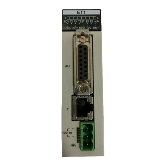
2.1 Names and Functions of Parts 2.1.1 Names and Functions of Parts Operating status LEDs These display the operating status of the unit, such as connection and communication conditions, and error statuses. 10BASE5(AUI) connector When an Ethernet (10BASE5) is being used, this connector is used to connect the ET-LAN unit and the transceiver, using a transceiver cable. -
Page 27: Operating Status Leds
2.1.2 Operating Status LEDs Flashing Connection 1 connected Connection 1 fault Connection 1 not connected Connection 2 connected Connection 2 fault Connection 2 not connected Connection 3 connected Connection 3 fault Connection 3 not connected Connection 4 connected Connection 4 fault Connection 4 not connected Connection 5 connected Connection 5 fault... -
Page 28: Connector Pin Layout
2.2 Connector Pin Layout 2.2.1 10BASE5(AUI) Connector (with D-SUB 15 pins retainer) Pin No. Signal name Pin No. Signal name Signal shield COL- COL+ Signal shield Signal shield 12 V DC Power supply shield Not used Not used Signal shield Shell F.G. -
Page 29: Connection For Lan Cable
Chapter 3 Connection for LAN Cable... -
Page 30: Precautions Concerning Installation
3.1 Precautions Concerning Installation Noise resistance The Ethernet is a network used in offices and buildings, where there is comparatively little noise. It does not have a higher resistance to noise than ordinary FA application networks. Consequently, caution is required when installing the transceiver and hub, and when laying cables. Guidelines to noise generation If any of the following are occurring, there is a danger that external noise is affecting the communication circuit. - Page 31 If it is impossible to avoid installing the equipment or cables near noise-generating equipment, the following measures should be taken. Place the programmable controller, transceiver, and hub inside metal panels. Place communication cables inside metal ducts. Attach a ferrite core near the ET-LAN unit of the communication cable. If using an external power supply terminal (12 V DC) for the ET-LAN unit, attach a ferrite core to the power supply cable.
-
Page 32: Connection For Lan Cable
3.2 Connection for LAN Cable 3.2.1 100BASE-TX and 10BASE-T Connections AFP2790 AFP27901 100BASE-T and 10BASE-T connections Connect the UTP cable to the 100BASE-TX/10BASE-T connector (RJ45) on the front panel of the ET- LAN unit. UTP cable Use Category 5 UTP cable. According to the ratings, Category 3 or better cable can be used with 10BASE-T, but we recommend that you use Category 5 UTP cable, which provides higher reliability. -
Page 33: 10Base5 (Aui) Connections
3.2.2 10BASE5 (AUI) Connections AFP2790 10BASE5(AUI) connections Connect the transceiver cable to the 10BASE5 (AUI) connector (with D-SUB 15 pins retainer) on the front panel of the unit. After you connect it, push down the retainer to fasten the cable. Transceiver and transceiver cable The transceiver that you use must comply with IEEE802.3. -
Page 34: Test Mode
3.3 Test Mode The ET-LAN unit has a test mode function that checks whether the unit is operating properly after it has been installed. 3.3.1 Types and Contents of Test Modes Contents of test mode Item Test mode 1 Test mode 2 Mode setting switch test Available Available... -
Page 35: Running Test Modes
3.3.2 Running Test Modes How the test modes are run Set the mode setting switches on the rear of the ET-LAN unit to the settings indicated in the table below, and then turn on the power supply to the programmable controller. When this has been done, either test mode 1 or test mode 2 can be run. - Page 36 Description of test content Confirmation method LED display Error code Item Description When when error TEST When error testing occurs * occurs The current status of the mode setting switches (1 to Visually check Mode setting 4) is displayed on LEDs C1 to C4. All the LEDs go Lights whether the LEDs switch test...
-
Page 37: Confirming The Design Contents
Chapter 4 Confirming the Design Contents... -
Page 38: Address Confirmation
4.1 Address Confirmation 4.1.1 IP Address Confirmation IP address confirmation An individual IP address is necessary in order to connect the ET-LAN unit to an LAN environment. Confirm the IP address with the person running the network system. If two or more ET-LAN units have been installed on one backplane, individual IP addresses should be allocated to each one. -
Page 39: I/O Allocations
4.2 I/O Allocations 4.2.1 Confirmation of I/O Allocations Allocating the ET-LAN unit A total of 32 inputs and 32 outputs can be allocated for the ET-LAN unit. If the I/O is not being used for the handshake, the programming tools can be used to specify [0SE], to set the number of occupied points to 0. -
Page 40: Confirmation Of Route Numbers
4.2.2 Confirmation of Route Numbers When MEWTOCOL communication is being used, if communication is being carried out with a node on a different hierarchical level, the route number is used to specify that route. These numbers are not necessary if the hierarchy link function is not being used. If multiple link-related units have been installed, they are numbered “route no. -
Page 41: Confirmation Of The Contents Of The Shared Memory
4.3 Confirmation of the Contents of the Shared Memory 4.3.1 Configuration of the Shared Memory Shared memory allocations The shared memory in the ET-LAN unit consists of the following areas. Note: Addresses for the above shared memory are in word (16-bit) units. The allocations (connections 1 to 3) for the transparent communication buffer area shown above show the statuses in effect when the unit is shipped from the factory. -
Page 42: The Roles Played By The Various Areas
4.3.2 The Roles Played by the Various Areas Initialization information setting area <Addresses 200H to 22FH> These are used in the initialization processing of the ET-LAN unit. These specify basic information such as the addresses and node numbers of source stations, and the re-send setting time for the TCP. - Page 43 Ladder send e-mail setting area <Bank 10H Addresses 000H to 03FH> Used when e-mails are sent using the ladder program. Used to specify the e-mail destination address and message. Auto connection status check area <Bank 10H Addresses 040H to 04FH> Used to check whether the auto connection function is used or not.
-
Page 44: Handshake Method
4.4 Handshake Method 4.4.1 Handshake Method Handshake method The CPU unit and ET-LAN unit carry out initialization and termination processing, open and close processing, various types of communication processing requests, and confirmation of completion by means of a handshake. There are two types of handshake, one using the I/O and one using the shared memory. Both types can be used at the same time. -
Page 45: Using The I/O For The Handshake
4.4.2 Using the I/O for the Handshake The I/O signals in the table below are used when a handshake is carried out between the CPU unit and the ET-LAN unit using the I/O. Input (Relay numbers indicate the numbers when installed in slot no. 0.) Description Description Receive notified signal (Connection 1) -
Page 46: Using The Shared Memory For The Handshake
4.4.3 Using the Shared Memory for the Handshake Complete signal area (bank 0) Expanded complete signal area (bank 0) Address Description Address Description 360H bit 0 364H bit 0 Receive notified signal (Connection 1) Receive notified signal (Connection 1) bit 1 Receive complete signal (Connection 1) bit 1 Receive complete signal (Connection 1) - Page 47 Complete signal area (bank 0) Expanded complete signal area (bank 0) Address Description Address Description 368H bit 0 Receive request signal (Connection 1) 36CH bit 0 Receive request signal (Connection 1) bit 1 bit 1 bit 2 bit 2 Transmission request signal (Connection 1) Transmission request signal (Connection 1) bit 3 bit 3...
- Page 48 Handshake using the shared memory When using the shared memory to carry out the handshake, internal relays should be allocated to teach of the signal areas, as shown in the program below. Program example Flow of processing when re-initialization and re-open processing are not carried out after a switch to RUN mode.
-
Page 49: Initialization Processing And Termination Processing
Chapter 5 Initialization Processing and Termination Processing... -
Page 50: Initialization/Termination Processing
5.1 Initialization/Termination Processing 5.1.1 What is Initializaiton Processing? Setting the various conditions for communication and booting the ET-LAN unit is called initialization processing. In initialization processing, the contents of the initialization information setting area and the routing information setting area in the shared memory of the ET-LAN unit are specified. If close processing has been completed for all of the connections, termination processing can be carried out to stop the ET-LAN unit. - Page 51 Operation of the ET-LAN unit The relationship between initialization processing and open processing...
-
Page 52: Processing Procedures
5.2 Processing Procedures 5.2.1 An Overview of the Initialization Processing Procedure The unit is initialized and booted using the following procedure. (1) The necessary data is written to the initialization information setting area (Bank: 0, Addresses 200H to 22FH) in the shared memory. (2) If communication is to be carried out between networks, the necessary data is written to the routing information setting area (Bank: 0, Addresses 230H to 24FH) in the shared memory. -
Page 53: An Overview Of The Termination Processing Procedure
5.2.2 An Overview of the Termination Processing Procedure The following procedure is used to stop operation of the unit. (1) Check to make sure that close processing has been completed for all of the connections. (2) Turn off the initialization request signal. (3) Check to make sure the initialization complete signal has gone off. -
Page 54: Writing Data To The Initialization Information Setting Area
5.2.3 Writing Data to the Initialization Information Setting Area The necessary data is written to the initialization information setting area (Bank 0: 0, Addresses: 200H to 22FH) of the shared memory using the shared memory writing instructions F151 (WRT) and P151 (PWRT). - Page 55 Default Address Name Setting value and explanation value TCP ULP Setting time = [Setting value (1 to FFFFH)] x 2 seconds (packet 000FH 20AH - With TCP, this specifies the time that a packet exists existence [30 seconds] when data transmission, etc. is carried out. duration) Setting time = [Setting value (1 to FFFFH)] x 2 seconds 0005H...
- Page 56 TCP ULP (packet existence duration) and TCP re-transmission timer value settings When TCP/IP communication is being carried out, data is automatically re-sent the specified number of times, as shown in the illustration below. Example: (when default settings are used) 20AH: TCP ULP = 000FH/30 seconds 20CH: TCP re-send timer value = 0005H/10 seconds Note: If the value set for the TCP ULP is smaller than that set for the TCP re-send timer, the data will not be...
- Page 57 Initialization information setting area 2 (bank 0) Default Address Name Setting value and explanation value [Set value] First address in receive buffer. - The first address of the receive buffer is specified using the absolute Receiving buffer starting address for transparent address (word address) of the 210H 2800H...
- Page 58 Default Address Name Setting value and explanation value Receiving buffer starting address for 220H FFFFH transparent communication Receiving buffer size for transparent 221H 0000H Connection communication Transmission buffer starting address 222H FFFFH for transparent communication Transmission buffer size for 223H 0000H transparent communication Receiving buffer starting address for...
- Page 59 Transparent communication buffer area allocations The transparent communication buffer area allocations (connections 1 to 3) effective when the unit is shipped from the factory are as shown below. The first addresses and sizes of the send and receive buffers of connections 1 to 8 can be sent to any desired values in the 6k words transparent communication buffer area by changing the contents of the initialization information settings.
-
Page 60: Writing Data To The Routing Information Setting Area
5.2.4 Writing Data to the Routing Information Setting Area When communication is to be carried out between networks, the necessary data is written to the routing information setting area of the shared memory (Bank 0: Addresses 230H to 24FH), using the shared memory writing instructions F151 (WRT) and P151 (PWRT). - Page 61 Routing information setting area 2 (bank 0) Default Address Name Setting value and explanation value FF000000H to FFFFFFFCH: Field value that determines network address or subnetwork address. - The network (subnetwork) mask is value that sets the 32-bit network address used as the IP address and the bit used for the subnetwork address to “1”.
- Page 62 Default Address Name Setting value and explanation value [Set value] Network (sub-network) address of destination node 235H Router 1 network (subnetwork) address (L) 0000H - This specifies the network (sub-network) address for an adjacent network connected through the router. 236H Router 1 network (subnetwork) address (H) 0000H - 00000000H and FFFFFFFFH will cause...
- Page 63 Router 1 to 5 and default router (gateway) settings The ET-LAN unit can communicate not only with the destination nodes on the source network, but also with destination nodes on other networks, through the router. There are two types of communication that can be carried out with destination nodes on other networks, as described below.
- Page 64 If the destination node exists in any of the <Other networks 1 to 5> noted above, the ET-LAN unit communicates with the node through routers 1 to 5. In this case, the network (sub-network) address of the destination node will match the “Network (sub-network) address of the destination node will match the “Network (sub-network) address”...
-
Page 65: Reading Initialization Information
5.3 Reading Initialization Information The initialization information subsequent to the initialization processing of the current unit can be read from the shared memory. The initialization information notified area (Bank: 0, Addresses: 2D0H to 2DFH) should be read using the shared memory read instruction F150 (READ) and P150 (PREAD). Initialization information notified area (bank 0) Address Name... - Page 66 Address Name Setting value and explanation 2D8H 2D9H 2DAH 2DBH Reserved (Used by the system.) 2DCH 2DDH 2DEH 2DFH 5-18...
-
Page 67: Sample Program
5.4 Sample Program This sample program assumes that the ET-LAN has been installed in slot no. 0. Program example Allocation of internal relays Classification Device number Device used in program example Complete signal area R0 to R1F RD: Initialization error signal Request signal area R40 to R5F R4C: Initialization request signal... - Page 68 5-20...
-
Page 69: Open Processing And Close Processing
Chapter 6 Open Processing and Close Processing... -
Page 70: Open/Close Processing
6.1 Open/Close Processing 6.1.1 What is Open Processing? Setting the connection information used to carry out communication with a partner node and enabling communication is called open processing. Connectors for up to eight connections can be opened with a single ET-LAN unit. The contents noted in the table below are set in the open information setting area of the shared memory in the unit for each connection. - Page 71 Operation of the ET-LAN unit The relationship between open processing and close processing...
-
Page 72: Types Of Open Processing
6.1.2 Types of Open Processing Open processing when using TCP/IP Transmission Control Protocol (TCP) is a type of connection protocol in which it is necessary to open mutual connections between the source and partner nodes before communication processing can be carried out. - Page 73 Fullpassive open (Passive connection open) The system is waiting for data to be received from a given partner node, in order to establish a connection. In the Fullpassive open method, the IP address and port number of the partner node are specified, and then the system waits for reception.
- Page 74 Active open (Active connection open) The connection is actively established. When the Active open is specified, the source node should not begin Active open processing until the partner node has begun Fullpassive/Unpassive open processing.
-
Page 75: Processing Procedures
6.2 Processing Procedures 6.2.1 An Overview of the Open Processing Procedure (1) The data required for communication with the partner node is set in the connection information setting area (Bank: 0, Addresses 250H to 2CFH). (2) The open request signal is turned on. Open request signal bit Hand- shake... -
Page 76: An Overview Of The Close Processing Procedure
6.2.2 An Overview of the Close Processing Procedure (1) Check to make sure the open complete signal is on. (2) Turn off the open request signal. (3) Check to make sure the open complete signal is off. Timing chart for open and close processing... -
Page 77: Writing Data To The Connection Information Setting Area
6.2.3 Writing Data to the Connection Information Setting Area The necessary data is written to the connection information setting area (Bank 0: Addresses 250H to 2CFH) of the shared memory using the shared memory writing instructions F151 (WRT) and P151 (PWRT). - Page 78 Offset address Offset Default Name Set value and Explanation address value [Set value] 1-word data that sets the communication conditions for the various connections as bit information. (a) Communication method Setting area Specify whether the communication method for each for application connection is TCP/IP or UDP/IP.
- Page 79 Offset Default Name Set value and Explanation address value [Set value] 1 to 40H (1 to 64) Partner node - Set the station number of the partner node when MEWTOCOL MEWTOCOL communication is being carried out. station 0000H - Avoid duplicating the number of another station on the number network.
-
Page 80: Reading Connection Information
6.3 Reading Connection Information The current statuses of the settings for the various connections can be read from the shared memory. Settings are read from the connection information notified area (Bank 0: Address 2E0H to 35FH) using the shared memory reading instructions F150 (READ) and P150 (PREAD). The connection information setting area consists of eight blocks, to match the number of connections. - Page 81 Key Point: Offset addresses 0 to 4 are stored after open processing has been completed. Offset addresses A to F are stored after communication processing has been completed, when using the transparent communication function. Offset address Offset Name Stored value and Explanation address [Stored value] 0: Open processing has been completed successfully.
- Page 82 Offset Name Stored value and Explanation address [Stored value] Copy of the size of the transparent received data remaining in the ET-LAN unit (in bytes). Transparent The same value as the transparent receive unnotified data size receive unnotified above is stored. data size copy If the two values match, the size of the transparent receive data will (connections 1 to 8)
- Page 83 Port number settings Port numbers are allocated in order for the various communication processes provided by the TCP/IP or UDP/IP to be differentiated by the programmable controller or the computer. The restrictions that apply to available port numbers are different for TCP/IP and UDP/IP, as indicated in the table below.
- Page 84 6-16...
-
Page 85: Computer Link Function
Chapter 7 Computer Link Function... -
Page 86: An Overview Of The Computer Link Function
7.1 An Overview of the Computer Link Function 7.1.1 What is the Computer Link Function? A computer link is a function that enables a computer to read data from, and write data to, the I/O or register of a programmable controller, and to read from and write to the contents of the registers and programs in the controller. -
Page 87: Commands And Functions Available For Use
7.1.2 Commands and Functions Available for Use MEWTOCOL-COM Commands Command name Code Description Read contact area Reads the on/off status of relays. (RCS) Specifies only one point. (RCP) Specifies multiple points. (RCC) Specifies a range in word units. Write contact area Turns relays on and off. - Page 88 Key Point: Commands and responses used with the ET-LAN unit have a dedicated header added to the “MEWTOCOL-COM” communication procedure of the FP series PLC. The contents of the specified header vary depending on the communication conditions. With the ET-LAN unit, in addition to ordinary MEWTOCOL, an expansion header is also supported that enables single frames of up to 2048 characters to be sent.
-
Page 89: Computer Link Procedure
7.2 Computer Link Procedure When computer link communication is being carried out on the programmable controller side, open processing is used to specify the MEWTOCOL communication mode and to open the connection with the partner node after initialization processing for the unit has been carried out. After a connection has been opened with the partner node computer, there is no need to run a communication program on the programmable controller side. -
Page 90: Settings On The Plc Side
7.3 Settings on the PLC Side 7.3.1 Connection Information Settings A memory area such as the data registers of the programmable controller is set aside, and the data to be written to the connection information area of the shared memory is specified when the open processing is carried out. - Page 91 Note: We recommend specifying a port number of 8000 (1F40) or higher. Specify a MEWTOCOL station number within a range of 1 to 64, choosing a number that does not duplicate any other station number on the same network. When using the Active open mode, if the partner node has no ARP function, specify the Ethernet address of the partner node for ”DTn+6 to DTn+8”.
-
Page 92: Writing To The Shared Memory
7.3.2 Writing to the Shared Memory The specified data is written to the connection information setting area of the shared memory using the shared memory writing instructions F151 (WRT) and P151 (PWRT). Shared memory address Program example If using connection 1 of the ET-LAN unit installed in slot no. 0, the program for writing data to the shared memory would be as follows. -
Page 93: Sample Program
7.3.3 Sample Program Program contents The sample program is for an ET-LAN unit installed in slot no. 0, and covers communication settings up to where the connection is opened as a result of the contents noted below. After the connection has been opened, no communication program is necessary on the PLC side. Internal relay allocation Classification Device number... - Page 94 Program example 7-10...
-
Page 95: Command Communication On The Computer Side
7.4 Command Communication on the Computer Side 7.4.1 Communication Data Format (1) Format when the partner node is on the same hierarchy level as the MEWTOCOL communication If there is no other link unit between the computer and the partner node, acting as a relay station, the partner node is said to be on the same hierarchy level as the computer. - Page 96 Format of command transmission data Format of response received data Precautions concerning format The number of bytes comprising the MEWTOCOL-COM command or message is converted to hexadecimal data and specified for the “Data Size” parameter. The station number of the station sending the command is specified for “Source for MEWTOCOL station number”.
- Page 97 Example of communication data (Same hierarchy communication) 7-13...
-
Page 98: Communication Data Format (2)
7.4.2 Communication Data Format (2) Format when the partner node is not on the same hierarchy level as the MEWTOCOL communication If there is another link unit between the computer and the partner node, acting as a relay station, the partner node is said to be on a different hierarchy level from the computer. - Page 99 The station number of the station sending the command is specified for “Source for MEWTOCOL station number”. The station number of the station receiving the command is specified for “Destination for MEWTOCOL station number”. With commands, the same value should be specified for the “Hierarchy level (LEVEL)” and “Hierarchy depth (DEPTH)”...
- Page 100 Example of communication data (Other hierarchy communication) 7-16...
- Page 101 Other hierarchy communication for MEWTOCOL-COM 7-17...
- Page 102 7-18...
-
Page 103: Data Transfer Function
Chapter 8 Data Transfer Function... -
Page 104: An Overview Of The Data Transfer Function
8.1 An Overview of the Data Transfer Function 8.1.1 What is the Data Transfer Function? With the data transfer function in the ET-LAN unit, program instructions (the SEND and RECV instructions) in the programmable controller are used to transfer data. Data can be transferred between the units indicated below. -
Page 105: Commands And Functions That Can Be Used
8.1.2 Commands and Functions that can be Used Data transfer commands and MEWTOCOL-DAT command messages Executing a data transfer command sends a MEWTOCOL-DAT command message to the partner node programmable controller, which then automatically returns a response message. When data is being sent from a programmable controller to a computer, the reception of the MEWTOCOL-DAT command message and the sending of the response message are handled on the computer side. -
Page 106: Data Transfer Procedure
8.2 Data Transfer Procedure When data is being transferred with a programmable controller, open processing is used to specify the MEWTOCOL communication mode and to open the connection with the partner node after initialization processing for the ET-LAN unit has been carried out. Procedure for transferring ET-LAN unit data... -
Page 107: Settings On The Plc Side
8.3 Settings on the PLC Side 8.3.1 Connection Information Settings A memory area such as the data registers of the programmable controller is set aside, and the data to be written to the connection information area of the shared memory is specified when the open processing is carried out. - Page 108 Note: Because the reliability of communication cannot be assured with UDP/IP, we recommend using TCP/IP. We recommend specifying a port number of 8000 (1F40) or higher. Specify a MEWTOCOL station number within a range of 1 to 64, choosing a number that does not duplicate any other station number on the same network (subnetwork).
-
Page 109: Writing To The Shared Memory
8.3.2 Writing to the Shared Memory The specified data is written to the connection information setting area of the shared memory using the shared memory writing instructions F151 (WRT) and P151 (PWRT). Shared memory address Program example If using connection 1 of the ET-LAN unit installed in slot no. 0, the program for writing data to the shared memory would be as follows. -
Page 110: Sample Program
8.3.3 Sample Program Program contents The sample program is for an ET-LAN unit installed in slot no. 0, and covers communication settings up to where the SEND instruction is executed after the connection is opened as a result of the contents noted below. - Page 111 Program example...
-
Page 112: Command Communication On The Computer Side
8.4 Command Communication on the Computer Side 8.4.1 Communication Data Format (1) Format when the partner node is on the same hierarchy level as the MEWTOCOL communication If there is no other link unit between the computer and the partner node, acting as a relay station, the partner node is said to be on the same hierarchy level as the computer. - Page 113 Format of command transmission data Format of response received data Precautions concerning format The number of bytes comprising the MEWTOCOL-COM command or message is converted to hexadecimal data and specified for the “Data Size” parameter. The station number of the station sending the command is specified for “Source for MEWTOCOL station number”.
- Page 114 Example of communication data (Same hierarchy communication) 8-12...
-
Page 115: Communication Data Format (2)
8.4.2 Communication Data Format (2) Format when the partner node is not on the same hierarchy level as the MEWTOCOL communication If there is another link unit between the computer and the partner node, acting as a relay station, the partner node is said to be on a different hierarchy level from the computer. - Page 116 Precautions concerning format The number of bytes comprising the MEWTOCOL-DAT command or message is converted to hexadecimal data and specified for the “Data Size” parameter. The “Station Number for Relay Station” and “Route Number for Relay Station” parameters should be specified using the pertinent number.
- Page 117 Example of communication data (Other hierarchy communication) 8-15...
-
Page 118: Communication Data Format (3)
8.4.3 Communication Data Format (3) Format when MEWTOCOL communication is being carried out from a PLC to a computer on the other hierarchy If there is another link unit between the PLC and the partner node, acting as a relay station, the PLC is said to be on a different hierarchy level from the computer. - Page 119 Other hierarchy communication for MEWTOCOL-DAT 8-17...
- Page 120 8-18...
-
Page 121: Transparent Communication Function
Chapter 9 Transparent Communication Function... -
Page 122: An Overview Of The Transparent Communication Function
9.1 An Overview of the Transparent Communication Function 9.1.1 What is the Transparent Communication Function? With the transparent communication function, data can be sent and received transparently between a computer and a programmable controller, and between two programmable controllers. Communication data can be stored to and retrieved from the programmable controller by reading from and writing to the reception buffer of the shared memory in the ET-LAN unit. -
Page 123: Transparent Communication Procedures
9.2 Transparent Communication Procedures To carry out transparent communication using an ET-LAN unit, initialization processing is first carried out for the unit, and then a connection is opened between the source node and the partner node, through open processing. Once this connection has been opened, communication processing is executed through the ladder program. -
Page 124: Settings On The Plc Side
9.3 Settings on the PLC Side 9.3.1 Connection Information Settings A memory area such as the data registers of the programmable controller is set aside, and the data to be written to the connection information area of the shared memory is specified when the open processing is carried out. -
Page 125: Writing To The Shared Memory
9.3.2 Writing to the Shared Memory The specified data is written to the connection information setting area of the shared memory using the shared memory writing instructions F151 (WRT) and P151 (PWRT). Shared memory address Program example If using connection 1 of the ET-LAN unit installed in slot no. 0, the program for writing data to the shared memory would be as follows. -
Page 126: Communication Processing For Transparent Communication
9.4 Communication Processing for Transparent Communication 9.4.1 Connection Processing Procedure Transmission processing The ET-LAN unit sends data through the communication circuit by writing it to the transmission buffer of the shared memory and then executing the transmission request. Reception processing When the ET-LAN unit receives data from the communication circuit, the reception notified signal goes on. - Page 127 Transmission and receive buffers The transparent communication buffer area allocations (connections 1 to 3) effective when the unit is shipped from the factory are as shown below. See page 5 – 10. The first addresses and sizes of the transmission and receive buffers of connections 1 to 8 can be set to any desired values in the 6k words transparent communication buffer area, by changing the contents of the initialization information settings.
-
Page 128: Procedure For Transmission Processing
9.4.2 Procedure for Transmission Processing Transmission processing timing chart Execution procedure when sending data The data to be sent in the transmission buffer. The size of the data to be sent is set in the transmission request data size parameter in the connection information setting area. - Page 129 Note: The transmission request data size in the connection information setting area is specified in byte units, and should be set such that the transmission request data size is less than or equal to the transmission buffer size x 2. The next time data is to be sent, always check to make sure the transmission complete signal is off b before executing the transmission processing.
-
Page 130: Procedure For Reception Processing
9.4.3 Procedure for Reception Processing Reception processing timing chart When the size of the data received is less than or equal to the reception request data size When the size of the data received is greater than the reception request data size 9-10... - Page 131 Procedure when receiving data When the size of the data received is less than or equal to the reception request data size, the following procedure is used to carry out communication processing. When data is received from the communication circuit, the receive notified signal goes on. The size of the data to be read is written to the reception request data size parameter in the connection information setting area.
- Page 132 Note: The size of the receive request data should be specified so that it is less than or equal to the size of the receive buffer x 2, and should be specified in byte units. The receive complete signal does not go on until the amount of data received is equal to the receive request data size in the connection information setting area.
-
Page 133: Handshake Signal And Data Area
9.4.4 Handshake Signal and Data Area Handshake signals used in transparent communication The handshake area of the I/O or the shared memory in the unit is used to execute communication processing. Related to transmission processing Transmission request signal bit Signal Handshake Connec- Connec-... - Page 134 Receive notified signal bit Signal Handshake Connec- Connec- Connec- Connec- Connec- Connec- Connec- Connec- name method tion 1 tion 2 tion 3 tion 4 tion 5 tion 6 tion 7 tion 8 Handshake using I/O Bank 0: Address 360H Handshake Bit 1 Bit 5 Bit 9...
- Page 135 Data areas used in transparent communication Related to transmission processing Connec- Connec- Connec- Connec- Connec- Connec- Connec- Connec- Name tion 1 tion 2 tion 3 tion 4 tion 5 tion 6 tion 7 tion 8 Transmission Bank 0: Bank 0: Bank 0: Bank 0: Bank 0:...
-
Page 136: Sample Program
9.5 Sample Program 9.5.1 Sample Program <Initialization to Open> Program contents This sample program assumes that the ET-LAN has been installed in slot no. 0. Internal relay allocation Classification Device number Devices used in program example Initialization complete signal Complete signal area R0 to R1F Initialization error signal Open error signal (Connection 1) - Page 137 Program example 9-17...
-
Page 138: Sample Program
9.5.2 Sample Program <Transmission Processing and Reception Processing> Program contents In this sample program, the ET-LAN has been installed in slot no. 0, and transmission or reception of data is being carried out after initialization to open processing has been completed. Internal relay allocation Classification Device number... - Page 139 Transmission processing After the data being transmitted has been written to the transmission buffer of the shared memory, the following program is run. 9-19...
- Page 140 Reception processing After the following program has been run, the received data is read from the receive buffer. 9-20...
-
Page 141: Sample Program
9.5.3 Sample Program <Reception to Transmission> Program example for transmitting received data as it is 9-21... - Page 142 Note: This applies when the default allocations are used for the transmission buffers. For this example, the ET-LAN unit has been installed in slot 0. Internal relay allocation Classification Device number Devices used in program example Receive complete signal Complete signal area R0 to R1F Transmission complete signal Transmission error signal...
-
Page 143: Auto Connection
Chapter 10 Auto Connection... -
Page 144: Auto Connection Function
10.1 Auto Connection Function What is Auto Connection Function? Auto connection function facilitates initialization processing and open processing setup of the ET-LAN unit not with the ladder program but with the dedicated setup tool (Configurator ET). Auto connection function is available when the mode setting switch 2 which is located on the back of the ET-LAN unit is turned ON. - Page 145 Auto open processing: When the auto connection function is ON (Setting mode switch 2 is ON) and a check mark is not placed in “The connection 1 to 8 are set by ladder program” check box with the dedicated setup tool (Configurator ET), the auto open processing is valid.
- Page 146 - Setup procedure using the auto connection function and setup tool (Configurator ET) For the auto connection function, it is necessary to set up each information (as shown in the diagram below) with the setup tool (Configurator ET). Configurator ET, the setup tool can be uploaded and downloaded irrespective of the auto connection function ON/OFF status.
-
Page 147: Reading Auto Connection Status Information
10.1.1 Reading Auto Connection Status Information The auto connection status check area (Bank: 10H, Addresses: 040H to 04FH) as shown in the diagram below can be read from the shared memory when the auto connection function is valid. In this process, connection status of System connections 1 to 3 and open processing method of Connections 1 to 8 set for the ET-LAN unit can be checked. -
Page 148: Auto Initialization Processing
10.1.2 Auto Initialization Processing What is Auto initialization processing? Based on the information set by the setup tool (Configurator ET), initialization processing is automatically conducted when the power is supplied. When this processing is performed, initialization processing using the ladder program is not required. Even if the initialization processing is set using the ladder program, the setting is ignored. -
Page 149: Auto Open Processing
10.1.3 Auto Open Processing What is Auto open processing? Based on the information set by the setup tool (Configurator ET), the open processing is automatically conducted to each connection of the ET-LAN unit when the power is supplied. When using the auto open processing, open processing for each connection by the ladder program is not necessary. -
Page 150: Auto Connection Information Settings
10.1.4 Auto Connection Information Settings Necessary data is set for the auto connection information setting items using the dedicated setup tool (Configurator ET). For the connection to be used, set the connection information settings as shown below. (Settings for up to 8 connections can be conducted.) - Auto connection information setting item Name... -
Page 151: Reading Auto Connection Information
10.1.5 Reading Auto Connection Information When the auto connection is valid, the auto connection information can be read in the same block as the connection information notified block of the conventional connection information notified area (Bank: 0, Addresses: 2E0H to 35FH). Additionally, other than the conventional information, the following information can be newly read. - Page 152 Offset Name Stored value/Explanation address Transparent receive [Stored value] processing complete 0: Receive processing has been completed successfully. code Other than 0: Error code (stored when the receive processing ended in an (Connections 1 to 8) error) ▪ Results are overwritten when receive processing is conducted again. ▪...
-
Page 153: Sample Program
10.1.6 Sample Program Data Transfer - Program contents Data is transferred between two ET-LAN units. The sample program is for an ET-LAN unit installed in Slot No. 0, and covers communication settings up to where the SEND instruction is executed after the connection is opened as a result of the contents noted below. - Page 154 Case 1 When the auto connection function is not used: Setting is performed only using the ladder program. The following settings are required using the ladder program. Setting item Setting method Internal relay allocation Ladder program Initialization processing Ladder program Open processing Ladder program Data transfer...
- Page 155 Case 1: Ladder program example 10-13...
- Page 156 Case 2-1 When the auto connection function is used (Configurator ET is used) and connection setting is performed using the ladder program, the following settings are required. When the initialization processing is set using the Configurator ET, the initialization processing is automatically conducted without setting the initialization processing using the ladder program.
- Page 157 - Setting using the ladder program Internal relay and data register allocation required for the ladder program are as shown below. Internal relay allocation Classification of processing Device number Device used in program example Complete signal area R0 to R1F RC: Initialization complete signal R0: Initialization error signal R11: Open error signal (Connection 1)
- Page 158 Case 2-1 Ladder program example Same as the one which the “X Programming is not required” section as shown below is deleted from the ladder program in Case 1. 10-16...
- Page 159 Case 2-2 When the auto connection function is used (Configurator ET is used) and connection setting is performed using the Configurator ET: The following settings are required using the ladder program. When the initialization processing is set using the Configurator ET, the auto initialization processing is automatically conducted without setting the initialization processing using the ladder program.
- Page 160 - Setting using the ladder program Internal relay and data register allocation required for the ladder program are as shown below. Internal relay allocation Classification Device number Device used in program example Complete signal area R0 to R1F RC: initialization complete signal RD: Initialization error signal R11: Open error signal (Connection 1) Request signal area...
- Page 161 Case 2-2 Ladder program example Same as the one which the “X Programming is not required” sections as shown below are deleted from the ladder program in Case 1. 10-19...
- Page 162 Transparent communication sample program - Program contents In this sample program, the ET-LAN has been installed in Slot No. 0 In this program, the contents of the transmission buffer (1K words) for Connection 1 are sent to the transmission side and received on the reception side using the transparent communication. When the auto connection function is available, use the setup tool (Configurator ET) to perform the initialization information settings and the connection information settings for both transmission and reception sides which are required for the open processing.
- Page 163 Setting using the ladder program Internal relay and data register allocation required for the ladder program are as shown below. (Common to transmission and reception sides.) Internal relay allocation (Common to transmission and reception sides) Classification Device number Device used in program example Complete signal area R0 to R1F R1: Receive complete signal...
- Page 164 Example of transparent communication program (Transmission processing) After the data being transmitted has been written to the transmission buffer of the shared memory, the following program is executed. Initialization processing and open processing are automatically executed. Example of transparent communication program (Reception processing) After the following program has been executed, the received data is read from the receive buffer of the shared memory.
-
Page 165: System Connection
10.2 System Connection What is System Connection? System connection is the connection set without using the ladder program, and dedicated for the programmable controller during computer link communication. For the system connection, three connections can be used as well as the existing 8 connections (Connections 1 to 8). Points: For the connection that the auto open processing is executed, the auto open processing setting may be ignored when the setup tool (Configurator ET) is used. -
Page 166: System Connection Information Setting
10.2.3 System Connection Information Setting Necessary data is set for the system connection information setting items using the dedicated setup tool (Configurator ET). For the connection to be used, set the connection information settings as shown below. (Settings for up to 3 connections can be conducted.) System connection information setting item Name... - Page 167 LED operation in the system connection “RMT” LED display status is as shown below. RMT LED Description When any connection among System connections 1 to 3 is effective and no error occurs. Flashing When an error occurs in any System connection (System connection 1, 2 or 3). When System connections 1 to 3 are not connected.
-
Page 168: Reading System Connection Information Settings
Application in which Connections 1 to 3 are used) For details, refer to 6.2.3 “Writing Data to the Connection Information Setting Area” of “FP2 ET-LAN Unit Technical Manual.” (ARCT1F322E) ▪ The value is not entered until auto open processing has been successfully completed. -
Page 169: E-Mail Function
Chapter 11 E-mail Function... -
Page 170: Outline Of E-Mail Function
11.1 Outline of E-mail Function ET-LAN unit supports three types of e-mail functions: “Error Notice Mail,” “Report Mail,” and “Device Watch Mail.” The fixed interval function that the ET-LAN unit checks received e-mails in the mail server can also be specified. These e-mail functions can be set using setup tool (Configurator ET). Reference: For details concerning setup procedures, refer to “Control Configurator ET Operational Guide Book”... -
Page 171: Precautions When Using The E-Mail Function
11.2 Precautions When Using the E-mail Function Check items before using the e-mail function Q1: Is ET-LAN unit installed in the network environment that can be connected with the e-mail server? → Proceed to Q2. → E-mails cannot be sent and received without using the e-mail server. →... - Page 172 E-mail function setting procedure using the setup tool (Configurator ET) Flow of e-mail function setting E-mail basic function Perform the server settings required for using the e-mail function. Concerning the necessary information, ask the server administrator. Perform the setting for the e-mail function E-mail settings to be used.
-
Page 173: Operation Environment
11.3 Operation Environment ET-LAN unit conducts the SMTP communication with the e-mail server (SMTP server) at Port No. 25 and the POP communication with the POP server at Port No. 110. E-mail communication cannot be conducted with the ports other than ones noted above. E-mails can be sent and received in the environment that Internet is available. -
Page 174: Sending/Receiving E-Mails Using E-Mail Function
11.4 Sending/Receiving E-mails Using E-mail Function Before sending and receiving e-mails with the ET-LAN unit, initialization processing for the ET-LAN unit must be completed. The e-mail function can be used regardless of the auto connection function status. That is, the e-mail function can be used either the mode setting switch 2 is ON or OFF. E-mail sending and receiving procedure using the ET-LAN unit Initialization / Reference:... -
Page 175: E-Mail Function
11.5 E-mail Function E-mail sending function Error Notice E-mail: When an error occurs in the CPU unit, a fixed message is sent to the specified destination. (The message of the e-mail cannot be edited.) Reference: For detailed setting procedure, refer to Chapter 4.3 of “Control Configurator ET Operational Guide Book.” (ARCT1F341E) For the error codes to be sent, see Chapter 10.6 “Error Codes”... - Page 176 Device Watch Mail: When a device of the programmable controller meets a certain condition (see Example below), an e-mail is sent to the designated destination. Example: Y0 turns ON or OFF, (Turning ON/OFF the flag) DT0 is 100, (Monitoring the device) DT0 is equal to the value of WR0, or (Comparing the devices) the value of DT1 becomes larger than the value of FL0...
- Page 177 - Request Mail function Response Mail: When the ET-LAN unit receives the request e-mail, it sends back a response e-mail to the e-mail source. Reference: Chapter 3.6 “Request Mail Function” 11-9...
-
Page 178: Security In Receiving E-Mails
11.6 Security in Receiving E-mails To enhance the safety in receiving e-mails, use the Mail Filter fucntion and a security password. - Flow of e-mail receiving steps - Mail Filter function Mail Filter function enables you to receive e-mails that satisfy the specified conditions when the ET-LAN unit receives e-mails. - Page 179 - Security password in receiving e-mails A security password is used for password authentication when receiving the request e-mail. For an e-mail that the ET-LAN unit receives, the password is authenticated to check if the received e- mail is a request e-mail. This function prevents CPU data from being read and written by an unauthorized e-mail.
-
Page 180: Outline Of Request E-Mail Function
11.7 Outline of Request E-mail Function Using the Request Mail function, data of the device that is monitored by the programmable controller can be read and written via e-mail. A Request Mail created based on the specified format can be sent to the ET-LAN unit with this function. After the ET-LAN unit receives the Request Mail, it automatically creates the Response Mail in answer to the request e-mail and sends back the Response Mail to the computer. -
Page 181: Request Mail Format
11.7.1 Request Mail Format - Format of Request Mail (Sent from a computer) The format of the request mail to be sent to ET-LAN unit is as follows: Example of a Request Mail Necessary settings for the e-mail to be sent (1) Subject: Enter “Request”... - Page 182 Format of Response Mail (Sent from a programmable controller) E-mail to be sent back from the ET-LAN unit is as follows: Example of a Response Mail (1) Subject: “Response” is entered in the “Subject” column in the Response Mail. (2) MEWTOCOL response: MEWTOCOL-COM response is sent back from the programmable controller.
-
Page 183: Sending E-Mail Using The Ladder Program
11.8 Sending E-mail Using the Ladder Program In the ladder send e-mail function, e-mails can be sent by the instruction using the ladder program. Using the ladder program of the CPU unit, the e-mail send processing is executed by turning ON the e- mail send request signal in the handshake area which is allocated in the ET-LAN unit. - Page 184 Time chart for e-mail send processing Procedure to send e-mails (1) Write the data that you wish to send via e-mail in the ladder send e-mail setting area. Reference: Chapter 3.7.2 “Ladder Send E-mail Settings” (2) The e-mail send request signal is turned ON. (3) When the e-mail send processing from the ET-LAN unit to the e-mail server is completed successfully, the e-mail send complete signal is turned ON.
-
Page 185: Ladder Send E-Mail Settings
11.8.2 Ladder Send E-mail Settings Before sending e-mails using the ladder program, be sure to confirm that the settings as shown below are registered using the setup tool (Configurator ET). E-mail address(es) specified for the destination address(es) (“To”, “Cc”, and “Bcc”) A message specified in Message No. -
Page 186: Sample Program (For Sending E-Mails)
11.8.3 Sample Program (for sending e-mails) This sample program is created on the assumption that the following settings are completed in advance using the setup tool (Configurator ET). E-mail addresses are registered in the Nos. 1, 6, and 32. A message is registered in the Message No. 1. Program contents The sample program is for the ET-LAN unit installed in Slot No. -
Page 187: Receiving E-Mails Using The Ladder Program
11.9 Receiving E-mails using the Ladder Program Whether e-mails are received or not can be checked by the instruction using the ladder program. E-mail receive processing is executed by turning ON the e-mail receive request signal in the handshake area which is allocated in the ET-LAN unit using the ladder program of the CPU unit. Reference: <Chapter 4 Confirming the Design Contents>... - Page 188 To conduct the e-mail receive processing once again, be sure to confirm that the e-mail receive error signal is OFF. Note: To receive e-mails using the ladder program, the following settings are required in advance using the setup tool (Configurator ET). Log-in name Password POP (e-mail) server IP address...
-
Page 189: Sample Program (For Receiving E-Mails)
11.9.1 Sample Program (for receiving e-mails) - Program contents The sample program is for the ET-LAN unit installed in Slot No. 0, and the following contents are received when the internal relay R301 turns ON. - Internal relay allocation Classification Device No. -
Page 190: E-Mail Error Log And E-Mail Log Functions
11.10 E-mail Error Log and E-mail Log Functions 11.10.1 What are the e-mail error logs and e-mail log functions The ET-LAN unit is equipped with a log buffer and an error log buffer; The log buffer records the communication information when sending/receiving e-mails. The error log buffer records the communication error information when sending/receiving e-mails. -
Page 191: Reading E-Mail Error Log
11.10.2 Reading E-mail Error Log - Contents of the error log block Up to 32 error log blocks can be registered in the e-mail error log area. (Send and receive errors are mixed in the area.) When the number of the error log block exceeds 32, the older log in the e-mail error log area’s last block is overwritten. - Page 192 - Time chart for reading e-mail error log - Procedure to read e-mail error logs (1) The e-mail error log notified request signal is turned ON. - The address 36AH (bit 5) in the e-mail request signal area (Bank: 0) is turned ON. (2) The e-mail error log is transferred to the shared memory.
-
Page 193: Reading E-Mail Logs
11.10.3 Reading E-mail logs - Contents of the send log block Send log blocks can be registered in the e-mail send log area. A newer e-mail send log is continuously registered in the starting send log block. When the number of the send log block exceeds 32, the older log that is stored in the e-mail send log area’s last block is overwritten. - Page 194 - Time chart for reading e-mail logs - Procedure to read e-mail logs (1) The e-mail log notified request signal is turned ON. ▪ The address 36AH (bit 4) in the e-mail request signal area (Bank: 0) is turned ON. (2) The e-mail logs (e-mail send log and e-mail receive log) are transferred to the shared memory.
-
Page 195: E-Mail Status Area
11.10.4 E-mail Status Area When the e-mail function is used, it can be checked that the ET-LAN unit normally sends/receives e- mails by means of the e-mail status area. After checking the e-mail status area: If the status is found to be as noted below, check the e-mail settings and re-set them if necessary. The e-mail send conditions set for the ET-LAN unit are met, but the number of e-mail send complete times and the number of e-mail send error are not counted. -
Page 196: Sample Program
11.10.5 Sample Program - Program contents The sample program is for an ET-LAN unit installed in Slot No. 0. The program processing is as shown below. When the internal relay signal R303 is turned ON, e-mail send log information is transferred to the e- mail send log area and e-mail receive log information is transferred to the e-mail receive log area. - Page 197 - Example of reading the e-mail send log area (Bank: 11H, Addresses: 000H to 1FFH) This send log block shows that the registered No. 3 e-mail message is sent at 4: 55 on Feb. 3 to the addresses specified as shown below: Address No.
- Page 198 - Example of reading the e-mail error log area (Bank: 10H, Addresses: 200H to 3FFH) Send error log block This error log block shows that the e-mail is received from the source address (etlan1_mail_test@xxx.yyy.zzz) at 1: 14 on Feb. 4. The contents of the block is the same as the one of the receive log block except for the added error codes.
-
Page 199: Troubleshooting Flowchart
11.11 Troubleshooting Flowchart The troubleshooting flowchart applicable for using the e-mail function is shown below. 11-31... - Page 200 11-32...
-
Page 201: Error Log Function
Chapter 12 Error Log Function... -
Page 202: Configuration Of The Error Log Area
12.1 Configuration of the Error Log Area 12.1.1 What is the Error Log Function? The ET-LAN unit is equipped with a log buffer where hardware and communication errors that occur in the unit are recorded. The contents of the log buffer are read by using the shared memory access instructions F150 (READ) and P150 (PREAD) and F151 (WRT) and P151 (PWRT) to read from and write to the error log area of the shared memory. - Page 203 Latest log block area Log block reading processing area 12-3...
-
Page 204: Contents Of Error Log Area
12.1.2 Contents of Error Log Area Error log area (bank 0) Address Name Explanation [Set value] (Default value: 0004H) The recorded error differs depending on the set value. Set value System error Recovery 380H Log mode possible error Warning error Access error E-mail error [Set value] Offset from latest log block of log buffer [Default value: 0000H]... -
Page 205: Reading The Error Log
12.2 Reading the Error Log 12.2.1 Procedure for Reading the Error Log Reading the latest log block The latest log block area in the error log area of the shared memory is read. The unit itself updates the contents of the latest log block area constantly, so it is not necessary to turn on the error log notified request signal. -
Page 206: Sample Program
12.2.2 Sample Program The sample program applies when the ET-LAN unit has been installed in slot no. 0. This program read the error log information to data registers DT60 to DT75. Internal relay allocation Classification Device number Devices used in sample program Receive complete signal Complete signal area R0 to R1F... -
Page 207: Error Code Contents
12.3 Error Code Contents 12.3.1 Access Error This error code notifies the user that processing ended abnormally. (The addresses indicated in the Description column is the address of bank 0 unless refused.) Code Name Description Step to take Remark 8000H Source node 0H or FFFFFFFFH was set for Correct the source node IP... - Page 208 Code Name Description Step to take Remark 8010H Open error An attempt was made to Run the open processing execute open processing after the initialization Open although initialization processing has been processing processing was not completed completed. end code successfully. There are also 8011H Application use...
- Page 209 Code Name Description Step to take Remark 8020H Transparent In transparent communication, Carry out communication an attempt was made to transmission Transmission transmission error execute transmission processing after processing end processing although initialization and code initialization processing was open processing not completed successfully.
- Page 210 Code Name Description Step to take Remark 8030H MEWTOCOL In MEWTOCOL Carry out The value at the transmission communication, an transmission left has been set error attempt was made to processing after for the send data although initialization and transmission initialization processing open processing completed code...
- Page 211 Code Name Description Step to take Remark 8041H MEWTOCOL A packet containing an error in Correct the setting for the The connection will reception error the MEWTOCOL node to which the be forcibly closed. communication format was MEWTOCOL received. A packet with a communication was sent hierarchy level (LEVEL) of 8 or (format content,...
-
Page 212: System Error
12.3.2 System Error This error code notifies the user if a critical system error has occurred. If this error occurs, the E2 LED on the front panel of the ET-LAN unit lights. Code Name Description Step to take Remark 9001H System error A watchdog error occurred (the The unit has run away. -
Page 213: Recovery Possible Error
12.3.4 Recovery Possible Error These error codes are displayed if an error occurs in the communication control unit. If one of these errors occurs, the E1 LED on the front panel of the ET-LAN unit flashes. Code Name Description Step to take Remark A001H UDP check sum... - Page 214 Code Name Description Step to take Remark A005H TCP/IP processing Error notification was received Carry out the transmission If any of error from the TCP. processing again. these errors No connection established: occur, the This notification is received if an If communication cannot be E1 LED on attempt was made to request...
-
Page 215: E-Mail Send Error
12.3.5 E-mail Send Error These error codes are displayed if an error occurs when sending e-mails. If one of these errors occurs, the E2 LED on the front panel of the ET-LAN unit flashes. Code Name Description Step to take Remark C000H SMTP server... -
Page 216: E-Mail Receive Error Transmission
12.3.6 E-mail Receive Error transmission These error codes are displayed if an error occurs when receiving e-mails. If one of these errors occurs, the E2 LED on the front panel of the ET-LAN unit flashes. Code Name Description Step to take Remark C100H POP server... -
Page 217: Mewtocol Error
12.3.7 MEWTOCOL Error This error code is displayed when the information of the CPU unit cannot be obtained with the e-mail sending function. If this error occurs, the E2 LED on the front panel of the ET-LAN unit flashes. Code Name Description Step to take... -
Page 218: Auto Connection Error
12.3.9 Auto Connection Error These error codes are displayed if an error occurs when using the auto connection function (auto connection, system connection). Code Name Description Step to take Remark B100H Auto Because the communication was - Check the communication Even if this disconnection not conducted for the specified... -
Page 219: Troubleshooting
Chapter 13 Troubleshooting... -
Page 220: Operation If An Error Occurs
13.1 Operation If an Error Occurs 13.1.1 Operation If the ALARM LED on the ET-LAN Unit Lights What the Alarm “ALM” LED does The alarm “ALM” LED on the ET-LAN unit lights if the watchdog timer in the unit is activated, to warn of a problem. -
Page 221: Operation If The "E1" Or "E2" Led On The Et-Lan Unit Lights Or Flashes
13.1.2 Operation If the “E1” or “E2” LED on the ET-LAN Unit Lights or Flashes How the ERROR LEDs work The ERROR LEDs on the ET-LAN unit light or flash when an error occurs in the unit itself, or when a communication error occurs. -
Page 222: What To Do If An Error Occurs
13.2 What to Do If an Error Occurs 13.2.1 If the Alarm "ALM" LED Lights on the ET-LAN Unit Situation The watchdog timer is activated to alert the user of a problem with ET-LAN unit. Solution Turn the power supply off and then on again. If the "ALM“... - Page 223 Key Point: The error log can be read using the programming tools and the following procedure. (1) On the “Tools” menu, select “Force Input/Output Function”. (2) Forcibly turn on the error log notified request signal (Y2F) and then turn it off again. This reads the error log into 390H and subsequent addresses of the shared memory.
-
Page 224: Troubleshooting Flowchart
13.2.4 Troubleshooting Flowchart 13-6... - Page 225 13-7...
-
Page 226: Reset Function
13.3 Reset Function 13.3.1 What is the Reset Function? The reset function is used to restart only the ET-LAN unit without cutting off the power supply for the system. Using the reset function enables the ET-LAN unit to be the operable state when an unrecoverable error has occurred in the ET-LAN unit. -
Page 227: Procedure Of Reset Function
13.3.3 Procedure of Reset Function Procedure 1. Write a value in the following address of the initial information setting area (Shared memory Bank 0) to execute the initial processing. Initial information setting area (Bank 0) Address Name Default Setting value/Explanation Reset the ET-LAN unit. -
Page 228: Reset Function Sample Program
13.3.4 Reset Function Sample Program Program contents The sample program is for the ET-LAN unit installed in Slot No. 0, and the reset function is executed when the communication of connection 1 stops (the no communication time-out signal of connection 1 is on) longer than 60 seconds after the open of connection 1. -
Page 229: Mewtocol Communication Procedure
Chapter 14 MEWTOCOL Communication Procedure... -
Page 230: Mewtocol-Com (Computer Link)
14.1 MEWTOCOL-COM (Computer Link) 14.1.1 Overview of MEWTOCOL-COM Command and response functions The computer sends commands (instructions) to the programmable controller, and receives responses in return. This enables the computer and programmable controller to converse with each other, so that various kinds of information can be obtained and provided. - Page 231 Note: With MEWTOCOL communication through an ET-LAN unit, a format is used in which the special header shown below is added to MEWTOCOL-COM commands and responses. Special header for ET- MEWTOCOL LAN unit command/response The content of the special header changes depending on the communication conditions. Control codes Name Character...
- Page 232 BCC (Block Check Code) The BCC is a code that carries out an error check using horizontal parity, to improve the reliability of the data being sent. The BCC uses an exclusive OR from the header (%) to the final character of the text, and converts the 8-bit data into a 2-character ASCII code.
- Page 233 How data is notated in commands and responses Data used in commands and responses can be notated in the three ways described below. Hexadecimal data and 16 to indicate hexadecimal data. (Example) Register contents in a data area read (RD) response Decimal data and x10 to indicate decimal data.
-
Page 234: Single Frames And Multiple Frames
14.1.2 Single Frames and Multiple Frames Single-frame commands and responses Maximum message length The maximum message length for a single frame of a command or response (the number of characters from the header to the terminator) is as indicated below. If the maximum message length is exceeded, the message should be split into multiple sections and sent (responses should be split into several frames and sent). - Page 235 Sample communication timing chart (1) Single-frame command and single-frame response (2) Multiple-frame command and single-frame response (3) Single-frame command and multiple-frame response (4) When multiple-frame command is aborted before being completed Note: When a transmission is split into several frames and sent, after one frame has been sent, the next frame cannot be sent until a transmission request message (*1 in the sample communication timing chart) has been received from the partner side.
-
Page 236: List Of Mewtocol-Com Commands
14.1.3 List of MEWTOCOL-COM Commands Table of command Command name Code Description Read contact area Reads the on and off status of contacts. (RCS) Specifies only one point. (RCP) Specifies multiple contacts. (RCC) Specifies a range in word units. Write contact area Turns contacts on and off. - Page 237 [RCS] Read contact area (single point) This reads the on and off status for only one contact. [RCP] Read contact area (plural point) 14-9...
- Page 238 [RCC] Read contact area (word units block) This reads the on and off status of the contact in word units. [WCS] Write contact area (single point) This turns only one contact on or off. 14-10...
- Page 239 [WCP] Write contact area (plural points) This turns multiple contacts on and off. [WCC] Write contact area (word units block) This turns a contact on or off in word units. 14-11...
- Page 240 [RD] Read data area This reads the contents of the data area. To read the contents of DT, LD, and FL: To read the contents of an index register: 14-12...
- Page 241 [WD] Write data area This writes the contents of the data area. To write the contents of DT, LD, and FL: 14-13...
- Page 242 To write to an index register: 14-14...
- Page 243 [RS] Read set value area This reads the value set for a time/counter. [WS] Write set value area This writes the value to be set for a timer/counter. 14-15...
- Page 244 [RK] Read elapsed value area This reads the elapsed value for a time/counter. [WK] Write elapsed value area This writes the elapsed value for a timer/counter. 14-16...
- Page 245 [MC] Register or Reset contacts monitored This registers a contact to be monitored. Up to 80 points can be registered for one unit. 14-17...
- Page 246 [MD] Register or Reset data monitored This registers data to be monitored. Up to 16 points can be registered for one unit. Note: If the data code is IX or IY, “0” should be specified for the four characters of the word number. Dummy registrations (“*”) are not possible when registering data to be monitored.
- Page 247 [MG] Monitoring start This monitors a contact or data that has been registered. Contact data is entered in the order registered, starting from bit 0 of the contact data Data is entered in the order registered, starting from the data 14-19...
- Page 248 [SC] Preset contact area (fill command) This embeds the areas of the specified range for 16 on and off points. [SD] Preset data area (fill command) This writes the same contents to the data area of the specified range. 14-20...
- Page 249 [RT] Read the status of PLC This reads information such as error codes if an error occurs in the programmable controller specifications. Model code This expresses the CPU unit type as a 2-character decimal value. Code Model FP2 and FP2SH Version This expresses the CPU unit version as a 2-character decimal value.
- Page 250 Operation mode The contents of special internal relays R9020 to R9027 are expressed as 2-character hexadecimal values. The user can check the settings of the mode selector switches on the CPU unit (RUN/PROG./REMOTE), whether normal operation or test operation is being used, and other elements. Values are read in binary notation, as shown below.
- Page 251 [RR] Read system register This reads the contents of the system registers. [WR] Write system register This sets the system registers. 14-23...
- Page 252 [RM] Remote control This switches the operation mode of the programmable controller. It is effective only when the operation mode of the programmable controller is the REMOTE mode. [AB] Abort If a transmission is aborted while a multiple-frame response is being received from the programmable controller, this is issued from the side sending the command (the computer side).
-
Page 253: Mewtocol-Dat (Data Transfer)
14.2 MEWTOCOL-DAT (Data Transfer) 14.2.1 Overview of MEWTOCOL-DAT Overview of command and response Notes: A dedicated procedure and conversational-style format are used. Data is sent as binary codes. Transmission rights are transferred each time a command message is sent. The maximum length for text data is 1,020 words. If the transmission source is a programmable controller, command messages are transmitted by executing the SEND and RECV commands. - Page 254 Command code and Response code Table of command Command code Description Corresponding response code Writing to a data area Reading from a data area Writing of contact information Reading of contact information Note: The corresponding response code is a value that is the reverse of the first bit (0 → 1) of the command code (1-byte binary code).
-
Page 255: List Of Mewtocol-Dat Commands
14.2.2 List of MEWTOCOL-DAT Commands [50H] Write data area The specified number of words of data are written, starting from the specified first word number of the data area. Area code Area type Area code Link relay (WL) Internal relay (WR) External output relay (WY) External input relay (WX) Timer/counter set value area (SV) - Page 256 [51H] Read data area The specified number of words of data are read, starting from the specified first word number of the data area. Area code Area type Area code Link relay (WL) Internal relay (WR) External output relay (WY) External input relay (WX) Timer/counter set value area (SV) Timer/counter elapsed value area (EV)
- Page 257 [52H] Write contact information Writing is carried out to the specified contact of the contact area. Area code Area type Area code Link relay (WL) Internal relay (WR) External output relay (WY) External input relay (WX) Timer/counter set value area (SV) Timer/counter elapsed value area (EV) Link data register (LD) Special internal relay (WR)
- Page 258 [53H] Read contact information Reading is carried out from the specified contact of the contact area. Area code Area type Area code Link relay (WL) Internal relay (WR) External output relay (WY) External input relay (WX) Timer/counter set value area (SV) Timer/counter elapsed value area (EV) Link data register (LD) Special internal relay (WR)
-
Page 259: Mewtocol Error Codes
14.3 MEWTOCOL Error Codes 14.3.1 Table of Error Code The same error codes are used for the computer link function and data link function. Link system error Error Error name Steps to take code WACK error The receive buffer of the partner node has overflowed. Steps to take: Keep the data size within the maximum range. - Page 260 Basic procedure error Error Error name Steps to take code When using the computer link function: BCC error A BCC error occurred in the command data. Steps to take: Use the application program to send the transmission again. Format error When using the computer link function: A command message was sent that does not fit the transmission format.
- Page 261 PLC application error Error Error name Steps to take code Parameter error When using the computer link function: The code used is for an area specification parameter that does not exist, or is a code that cannot be used with that command (X, Y, D, etc.). An inappropriate code is being used for the function specification parameter (0, 1, 2, etc.).
- Page 262 14-34...
-
Page 263: Specifications
Chapter 15 Specifications... -
Page 264: Tables Of Performance Specifications
15.1 Tables of Performance Specifications 15.1.1 General Specifications Item Description 0 to 55 °C Ambient temperature -20 to 70 °C Storage temperature Ambient humidity 30 to 85%RH (at 25°C, no-condensing) Storage humidity Vibration resistance 10 to 55 Hz, 1 cycle/min.: double amplitude o f0.75 mm, 10 min. on 3 axes Shock resistance 98 m/s2, 4 times on 3 axes Noise resistance... -
Page 265: Communication Specifications
Note1) It is possible to set the unit type to “0SE” by using a programming tool such as FPWIN GR. Note2) Remote programming and monitoring through the LAN are available using the programming tool such as FPWIN GR. (Configurator ET does not support the connection via LAN.) Note3) The usable functions vary according to the version of the used ET-LAN unit. -
Page 266: I/O Allocation
15.2 I/O Allocation The I/O signals in the table below are used when a handshake is carried out between the CPU unit and the ET-LAN unit using the I/O. Input (Contact numbers indicate the numbers when installed in slot no. 0) Description Description Receive notified signal (Connection 1) -
Page 267: Table Of Shared Memory
15.3 Table of Shared Memory Initialization information setting area (Bank 0) Address Name Default Set value and explanation 200H Source node IP address 0000H [Set value] Source node address - Address example: 192.168.1.1 (C0 A8 01 01H) IP address (L): 0101H 201H Source node IP address 0000H... - Page 268 Address Name Default Set value and explanation 208H 0000H Set the base time for the no communication connection communication detection timer value. connection time 0000H : x 2 minutes type Other than 0000H : x 6 seconds 209H 0000H Setting time = [Setting value (1 - FFFFH)] x [Base time] communication - Set the time to detect a no-communication state after connection...
- Page 269 Address Name Default Set value and explanation 210H Receiving buffer starting address for 2800H [Set value] First address in receive buffer. transparent communication - The first address of the receive buffer is specified (Connection 1) using the absolute address (word address) of the shared memory when transparent communication is being carried out among the various connections.
- Page 270 Address Name Default Set value and explanation 21CH Connection 4 Receiving buffer starting address for FFFFH - The first address in each buffer transparent communication should specified using 2800H 3FFFH (word 21DH Receiving buffer size for transparent 0000H address). communication - See address “210H to 213H”.
- Page 271 Routing information setting area (Bank 0) Address Name Default Set value and explanation 230H Network 0000H FF000000H to FFFFFFFCH: Field value that determines network (subnetwork) address or subnetwork address. masking (L) - The network (subnetwork) mask is a value that sets the 32-bit network address used as the IP address and the bit used for the 231H Network...
- Page 272 Address Name Default Set value and explanation 232H Default router 0000H [Set value] Default router (gateway) IP address (Gateway) IP - This is effective as long as the network (subnetwork) mask field is address (L) anything other than 0. - If the default router (gateway) IP address has been set, 233H Default router 0000H...
- Page 273 Address Name Default Set value and explanation 239H Router 2 Network (subnetwork) address (L) 0000H Refer to address “235H to 238H” 23AH Network (subnetwork) address (H) 23BH Router IP address (L) 23CH Router IP address (H) 23DH Router 3 Network (subnetwork) address (L) 0000H 23EH Network (subnetwork) address (H)
- Page 274 Connection information setting area (Bank 0) Offset Name Default Set value and explanation address Setting area for 0000H [Set value] 1-word data that sets the communication conditions for application being the various connections as bit information. used (connections 1 to 8) (a) Communication method Specify whether the communication method for each connection is TCP/IP or UDP/IP.
- Page 275 Offset Name Default Set value and explanation address Source node 0000H [Set value] TCP or UDP communication process port number. port No. - Set any port number other than 0H (a value of 1025 (401H) or higher is (connections 1 recommended).
- Page 276 Initialization information notified area (Bank 0) Address Name Stored value and explanation 2D0H Initialization processing [Stored value] 0: Initialization processing was completed successfully. complete code Other than 0: Error code (Initialization processing ended in an error) 2D1H Source node IP address [Stored value] Source node IP address when initialization processing was completed successfully.
- Page 277 Connection information notified area (Bank 0) Offset address Offset Name Stored value and explanation address Open processing [Stored value] 0: Open processing has been completed successfully. complete code Other than 0: Error code (when open processing ended in an error) (connections 1 to 8) - If re-open processing is carried out, the results are overwritten.
- Page 278 Offset Name Stored value and explanation address Transparent receive [Stored value] 0: Receive processing completed normally. processing complete Other than 0: Error code (when the receive processing ended in an error) code - Result is overwritten when receive processing is done again. (connections 1 to 8) - The error code is stored in the error log area.
- Page 279 Ladder send e-mail setting area (Bank: 10H) Address Name Default Set value/Explanation 000H Destination address 1 0000H [Default] 0 to FFFFH (For “To”) Nos. of the destination addresses (for “To”, “Cc”, and “Bcc”) (Address Nos. 1 to 17) which are registered in the Address Book by means of Configurator ET can be specified.
- Page 280 - Auto connection status check area (Bank: 10H) Address Name Explanation 040H Auto connection function 0: Auto connection function is invalid. status 1: Auto connection function is valid. 041H Normal connections 1 to 8 0: Setup tool setting is valid. (Ladder program setting is invalid.) Open processing setting 1: Ladder setting is valid.
- Page 281 System connection information notified area (Bank: 10H) System connection information notified block (Bank: 010H, Addresses 010H to 03FH) Offset Name Stored value/Explanation address Open processing complete code [Stored value] (System connections 1 to 3) 0: Auto open processing has been completed successfully. Other than 0: Error code (when auto open processing ended in an error.) - Error logs are also stored in the error log area.
- Page 282 E-mail status area (Bank: 10H) Address Name Description - The number of times that e-mails have been sent normally is stored. 080H Number of e-mail send - The value is reset to “0” when the initialization processing is executed or complete times the e-mail setting is changed.
- Page 283 Handshake area Complete signal area (Bank: 0) Expanded complete signal area (Bank: 0) Address Description Address Description bit 0 Receive notified signal (Connection 1) bit 0 Receive notified signal (Connection 1) bit 1 Receive complete signal (Connection 1) bit 1 Receive complete signal (Connection 1) bit 2 Send complete signal...
- Page 284 Request signal area (Bank: 0) Expanded request signal area (Bank: 0) Address Description Address Description bit 0 Receive request signal (Connection 1) bit 0 Receive request signal (Connection 1) bit 1 bit 1 bit 2 Send request signal (Connection 1) bit 2 Send request signal (Connection 1)
- Page 285 Error log area (Bank 0) Address Name Explanation 380H Log mode [Set value] [Default: 0003H] The recorded error differs depending on the set value. A: Available N/A: Not available Set value System error Recovery possible error Warning error Access error 381H Log block reading [Set value] Offset from latest log block of log buffer [Default: 0000H]...
- Page 286 Address Name Explanation 388H Latest log block area [Stored value] Latest log information (8 words) - The unit itself updates the contents constantly, so information can be read 38FH using the shared memory access instructions F150 (READ) and P150 (PREAD), without issuing a read request. - This is cleared to 0 when initialization processing is carried out.
-
Page 287: Table Of Related Relays, Registers And Instructions
15.4 Table of Related Relays, Registers and Instructions 15.4.1 System Register Item Address Name Default Description (*) Action on Operation settings when an Stop Stop/continuation error for intelligent unit error occurs FP2 and Operation settings when an Stop Stop/continuation FP2SH I/O verification error occurs 240 µs 0 to 52428 µs... -
Page 288: Special Internal Relay
15.4.2 Special Internal Relay Address Name Description R9003 Intelligent unit error flag Turns on when an error occurs in an intelligent unit. The slot number where the erroneous intelligent unit is installed is stored in DT90006 or DT90007. R9004 I/O verification error flag Turns on when an I/O verification error occurs. -
Page 289: System Register
15.4.3 System Register Register No. Name Description FP10SH/ FP2/FP2SH DT9006 DT90006 Abnormal intelligent unit When an error condition is detected in an intelligent (Slot No. 0 to 15) unit, the bit corresponding to the slot of the unit will be set to on. -
Page 290: Minimum Transmission Delay Time
15.5 Minimum Transmission Delay Time The minimum transmission processing time for MEWTOCOL communication and transparent communication is determined using the formulas below. This calculation serves as a general guide for the transmission time, assuming that there is one connection being used, no other nodes exist on the network, and 1:1 communication is being carried out. - Page 291 Transparent communication The following is a guide to the transmission time when the ET-LAN unit is sending or receiving data. When using TCP/IP: Transmission processing time = 0.017 x no. of transmission data bytes + 8 (ms) Receive processing time = 0.005 x no. of receive data bytes + 8 (ms) When using UDP/IP: Transmission processing time = 0.017 x no.
-
Page 292: Ascii Codes
15.6 ASCII Codes 15-30... -
Page 293: Dimensions
15.7 Dimensions AFP2790 (FP2-ET1) AFP27901 (FP2-ET2) 15-31... -
Page 295: Sample Program
Chapter 16 Sample Program... -
Page 296: An Overview Of The Sample Program
16.1 Sample Program 16.1.1 An Overview of the Sample Program This is a sample program in which data is being sent and received between an ET-LAN unit and a workstation. System configuration Setting conditions Items ET-LAN unit Workstation IP address 192.9.210.130 If the network ID is the same as that of the ET-LAN unit, no host... -
Page 297: Workstation Sample Program
16.1.2 Workstation Sample Program The following shows an example of the “make file“ and “source file“ of the sample program run at the workstation. make file source file 16-3... - Page 298 16-4...
- Page 299 16-5...
- Page 300 16-6...
- Page 301 16-7...
-
Page 302: Communication Setting Program On Plc Side
16.1.3 Communication Setting Program on PLC Side When the PLC is put in RUN mode, initialization and open processing are carried out for the ET-LAN unit, and “01“ is set for the MEWTOCOL station number. Internal relay allocation Classification Device number Devices used in sample program Complete signal area R0 to R1F... - Page 303 Record of changes Manual No. Date Description of changes ARCT1F322E/ APR.2001 First edition ACG-M322E ARCT1F322E-1/ NOV.2001 Second edition ACG-M322E-1 Chapter12 Page12-5,12-10,12-11to12-13:corrected Page12-25,12-28:corrected ARCT1F322E-2/ NOV.2006 Third edition ACG-M322E-2 ARCT1F322E-3/ NOV.2008 Fourth edition ACG-M322E-3 - Change in Corporate name ARCT1F322E-4/ NOV.2009 Fifth edition ACG-M322E-4 - Addition of ET-LAN2 Unit AFP27901 - Addition of ARCT1F370E-2 (Additional vertion)
- Page 306 ■ Overseas Sales Division (Head Office): 2431-1 Ushiyama-cho, Kasugai-shi, Aichi, 486-0901, Japan ■ Telephone: +81-568-33-7861 ■ Facsimile: +81-568-33-8591 panasonic.net/id/pidsx/global About our sale network, please visit our website. © Panasonic Industrial Devices SUNX Co., Ltd. 2013 December, 2013 PRINTED IN JAPAN ARCT1F322E-7...