HP 8924C User Manual
Cdma mobile station test set
Hide thumbs
Also See for HP 8924C:
- Application manual (359 pages) ,
- Assembly (640 pages) ,
- Reference manual (469 pages)
Table of Contents
Advertisement
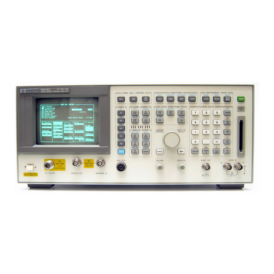
HP 8924C CDMA Mobile Station Test Set
Firmware Version A.07.04 and above
POWER
!
MAX PWR
6 W
DO NOT APPLY
!
RF WHEN OFF
RF IN/OUT
DUPLEX OUT
User's Guide
CDMA CALL CONTROL
END
CALL
ANS
CALL
USER
CDMA SCRNS
k1'
CELL
RANGE
CALL
RX
k1
CTRL
TEST
k2'
SPECTRUM
MSRPT
GEN
TX
k2
CTRL
TEST
k3'
k3
ANALOG SCRNS
ASSIGN
ENCODER
DECODER
RF
RX
k4
ANL
TEST
RELEASE
ACP
AF
TX
k5
ANL
TEST
SPEC ANL
SCOPE
RF
SHIFT
DUPLEX
GEN
MIC/ACC
!
MAX PWR
200 mW
ANTENNA IN
HP Part No. 08924-90038
Printed in U. S. A.
November 1999
Rev. F
FUNCTIONS
INSTRUMENT STATE
MSG
PRINTER
I/O CONFIG
CONFIG
ADRS
SAVE
HELP
PRINT
PREV
TESTS
LOCAL
RECALL
DATA FUNCTIONS
DATA
REF SET
METER
AVG
INCR
INCR
INCR X10
7
8
9
: 10
SET
LO LIMIT
HI LIMIT
4
5
6
CURSOR
PUSH TO
CONTROL
SELECT
1
2
3
+ _
0
YES
NO
ppm
ON/OFF
CANCEL
W
dBµV
VOLUME
SQUELCH
AUDIO OUT
HI
MAX
!
12 v Pk
HOLD
MEAS
PRESET
RESET
MEMOR
Y CARD
ENTER
dB
GHz
dBm
%
MHz
V
s
kHz
mV
Ω
ms
%
Hz
µV
AUDIO IN
LO
MAX
!
42 v Pk
1
Advertisement
Table of Contents

Related Manuals for HP HP 8924C


Summary of Contents for HP HP 8924C
- Page 1 HP 8924C CDMA Mobile Station Test Set User’s Guide Firmware Version A.07.04 and above CDMA CALL CONTROL FUNCTIONS INSTRUMENT STATE PRINTER I/O CONFIG CONFIG ADRS SAVE HOLD MEAS CALL HELP PRINT PREV TESTS LOCAL RECALL PRESET CALL RESET MEMOR Y CARD...
- Page 2 Copyright © Hewlett-Packard Company 1996 Notice Information contained in this document is subject to change without notice. All Rights Reserved. Reproduction, adaptation, or translation without prior written permission is prohibited, except as allowed under the copyright laws. This material may be reproduced by or for the U.S. Government pursuant to the Copyright License under the clause at DFARS 52.227-7013 (APR 1988).
- Page 3 Manufacturer’s Declaration This statement is provided to comply with the requirements of the German Sound Emission Directive, from 18 January 1991. This product has a sound pressure emission (at the operator position) < 70 dB(A). Sound Pressure Lp < 70 dB(A). •...
- Page 4 Safety GENERAL Considerations This product and related documentation must be reviewed for familiarization with safety markings and instructions before operation. This product has been designed and tested in accordance with IEC Publication 1010, "Safety Requirements for Electronic Measuring Apparatus," and has been supplied in a safe condition.
- Page 5 Safety Considerations for this Instrument WARNING This product is a Safety Class I instrument (provided with a protective earthing ground incorporated in the power cord). The mains plug shall only be inserted in a socket outlet provided with a protective earth contact. Any interruption of the protective conductor inside or outside of the product is likely to make the product dangerous.
- Page 6 CAUTION: Always use the three-prong ac power cord supplied with this product. Failure to ensure adequate earth grounding by not using this cord may cause product damage. This product is designed for use in Installation Category II and Pollution Degree 2 per IEC 1010 and IEC 664 respectively.
- Page 7 HP from another country. HP warrants that its software and firmware designated by HP for use with an in- strument will execute its programming instructions when properly installed on that instrument. HP does not warrant that the operation of the instrument, or software, or firmware will be uninterrupted or error free.
- Page 8 24001 E. Mission Avenue Liberty Lake, Washington 99019-9599 declares that the product CDMA Mobile Station Test Set Product Name: HP 8924C Model Number: This declaration covers all options of the above Product Options: product. conforms to the following Product specifications:...
- Page 9 If you have used the manuals and still have application questions, contact your local HP Sales Representative. Repair assistance is available for the HP 8924C CDMA Mobile Test Set from the factory by phone and e-mail. Internal Hewlett-Packard users can contact the factory through HPDesk or cc:Mail©...
- Page 10 United States of America United States of America United Kingdom U.S. Instrument Support Center Customer Information Center Sales and Service For Test & Measurement Equipment For Assistance On All HP Hewlett-Packard Ltd. Repair & Calibration. Products. Cain Road Hewlett-Packard Company Hewlett-Packard Company...
- Page 11 Table 1 Regional Sales and Service Offices (Continued) Canada Latin America Service Center Hewlett-Packard Company Hewlett-Packard Ltd. LAHQ Mexico City 11120 178 Street Col. Lomas de Virreyes Edmonton, Alberta T5S 1P2 11000 Mexico D.F. Canada Mexico Telephone: (403) 486-6666 Telephone: (52/5) 326-4000 Fax: (403) 489-8764 Fax: (52/5) 202 7718...
- Page 12 In this Book Throughout this manual the term "Test Set" is used to denote the HP 8924C. Test Set screens shown in this manual may not match those displayed on the Test Set in every detail. Chapter 1, Getting Started...
-
Page 13: Table Of Contents
1 Getting Started Before Connecting a Radio 22 Accessing the Test Set’s Screens 23 Changing A Field’s Setting 26 Obtaining Measurement Results 30 Control Annunciators 35 Addressing 36 HP-IB Command Guidelines 37 Verifying that the Test Set is Operating Properly 42 S:\HP8924C\USRGUIDE\BOOK\24cug.TOC... - Page 14 Contents 2 Configuring Your Test Set General Operating Information 44 S:\HP8924C\USRGUIDE\BOOK\24cug.TOC...
- Page 15 Triggering Analog Measurements In Local Mode (Front Panel Operation) 76 Triggering CDMA Measurements In Local Mode (Front Panel Operation) 79 Triggering Analog Measurements In Remote Mode (HP-IB Operation) 82 Triggering CDMA Measurements In Remote Mode (HP-IB Operation) 84 Increasing Measurement Throughput 86 Passing Instrument Control 94 S:\HP8924C\USRGUIDE\BOOK\24cug.TOC...
- Page 16 Contents 4 Status Reporting Status Reporting 108 S:\HP8924C\USRGUIDE\BOOK\24cug.TOC...
- Page 17 Contents 5 Memory Cards/Mass Storage Default File System 208 Mass Storage Device Overview 210 Default Mass Storage Locations 217 Mass Storage Access 219 DOS and LIF File System Considerations 220 Using the ROM Disk 225 Using Memory Cards 226 Backing Up Procedure and Library Files 232 Copying Files Using IBASIC Commands 233 Using RAM Disk 235 Using External Disk Drives 237...
- Page 18 Contents 6 IBASIC Controller Introduction 240 The IBASIC Controller Screen 241 Important Notes for Program Development 243 Program Development 244 Interfacing to the IBASIC Controller using Serial Ports 246 Choosing Your Development Method 261 Method #1. Program Development on an External BASIC Language Computer 263 Method #2.
- Page 19 Contents Index 341 S:\HP8924C\USRGUIDE\BOOK\24cug.TOC...
- Page 20 Contents S:\HP8924C\USRGUIDE\BOOK\24cug.TOC...
-
Page 21: Getting Started
1 Getting Started This chapter will help familiarize you with fundamental Test Set operation, including: • Accessing screens and fields • Making a simple measurement • Preparation for remote operation via HP-IB S:\HP8924C\USRGUIDE\BOOK\chapters\getstart.fb... -
Page 22: Before Connecting A Radio
Chapter 1, Getting Started Before Connecting a Radio Before Connecting a Radio NOTE: The RF IN/OUT port should be used for all transmitter tests when the radio is connected directly to the Test Set. (All MSUT (Mobile Station Under Test) transmitter power measurements are made through this port). -
Page 23: Accessing The Test Set's Screens
ANLG SCRNS keys, or • select a screen from the Analog To Screen menu, or • programmatically select an analog screen using the display (DISP) HP-IB subsystem, • execute a CDMA to Analog handoff. To enter CDMA mode from analog mode: •... - Page 24 Chapter 1, Getting Started Accessing the Test Set’s Screens Functions Screens Screens that control various instrument functions such as configuration, access to the Tests subsystem, and the PREV (previous screen) key are found under the front-panel “Functions” bracket. CDMA Digital Transceiver Measurements Instrument Functions Analog Transceiver Tests CDMA CALL CONTROL...
- Page 25 Chapter 1, Getting Started Accessing the Test Set’s Screens Cursor Control CDMA CALL CONTROL FUNCTIONS INSTRUMENT STATE PRINTER I/O CONFIG CONFIG ADRS SAVE HOLD MEAS CALL HELP PRINT PREV TESTS LOCAL RECALL PRESET CALL RESET MEMOR Y CARD USER CDMA SCRNS DATA FUNCTIONS DATA k1’...
-
Page 26: Changing A Field's Setting
2. Press a key labeled with a different unit-of-measure (such as W). 3. If the new units are valid, the measurement value will be displayed in the new unit-of- measure. To change the units-of-measure for data transfer via HP-IB, see "To Specify Units- of-Measure for HP-IB Data Transfer" in chapter 3... - Page 27 Chapter 1, Getting Started Changing A Field’s Setting Underlined Immediate-Action Field Figure 3 Underlined Immediate-Action Field Underlined immediate action fields provide a choice of two settings. See to see an example of an underlined immediate-action field. figure 3 To change an underlined entry 1.
- Page 28 Chapter 1, Getting Started Changing A Field’s Setting One-of-Many Field Figure 4 One-of-Many Field One-of-many fields display a list of choices when selected. See figure 4 see an example of a one-of many field. To make a one-of-many choice 1. Position the cursor at the field. 2.
- Page 29 Chapter 1, Getting Started Changing A Field’s Setting Numeric-Entry Field Figure 5 Numeric-Entry Field Numeric-entry fields contain numeric values. See to see an figure 5 example of a numeric-entry field. To change a value 1. Position the cursor at the field. 2.
-
Page 30: Obtaining Measurement Results
When operated remotely, measurement results are obtained via HP-IB by triggering a measurement if necessary and querying the desired measurement field. - Page 31 Obtaining Measurement Results Preparing the Test Set for HP-IB Control 1. If other HP-IB devices are in the system, attach an HP-IB cable from the Test Set’s rear- panel HP-IB connector to any one of the other devices in the test system.
- Page 32 1. For each measurement you want to perform programmatically, make the measurement manually using the front-panel controls of the Test Set. You will find procedures for making measurements in the HP 8924C Application Guide. Record, in sequential order, the screens selected and the settings made within each screen.
- Page 33 "Command Punctuation" on page 38 The bus address 714 used in the following BASIC language examples uses an HP- IB interface at select code 7, and a Test Set HP-IB address of 14. All examples use an external controller. To Change a Field’s Setting 1.
- Page 34 Condensed Programming Reference Guide for the proper variable type). NOTE: Whenever a numeric value is queried, the returned value is always in HP-IB Units. Refer to "To Specify Units-of-Measure for HP-IB Data Transfer" on page The following example program illustrates how to make settings and then take a reading from the Test Set.
-
Page 35: Control Annunciators
Chapter 1, Getting Started Control Annunciators Control Annunciators The letters and symbols at the top right corner of the display indicate these conditions: R indicates the Test Set is in remote mode. The Test Set can be put into the remote mode by an external controller or by an IBASIC program running on the built-in IBASIC con- troller. -
Page 36: Addressing
0 to 30 using the numeric DATA keys, or by pushing and then rotating the CURSOR CONTROL knob. There are no switches for setting the HP-IB bus address in the Test Set. The new setting is retained when the Test Set is turned off. -
Page 37: Hp-Ib Command Guidelines
HP-IB Command Guidelines HP-IB Command Guidelines Command Names HP-IB commands are not case sensitive. Upper and lower case characters can be used for all commands. For example, to set the destination of AF Generator 1 to Audio Out, any of the following command strings are valid: “AFGENERATOR1:DESTINATION ’AUDIO OUT’”... - Page 38 It is therefore necessary that the equivalent form of the correct punctuation, as defined by the language, be used for HP-IB operation. Improper punctuation will result in HP-IB Error: -102 Syntax Error.
- Page 39 Using the Semicolon Colon (;:) to Separate Commands A semicolon followed by a colon (;:) tells the HP-IB command parser that the next command is at the top level of the command hierarchy. This allows commands for different instruments to be output on one command line. The following example sets the RF Analyzer’s tune frequency to 850 MHz, and then sets the AF...
- Page 40 Hewlett-Packard Rocky Mountain BASIC (RMB). To run this program directly in the Test Set’s IBASIC Controller: 1. use exclamation marks (!) to comment-out lines 440, 450, and 460 (these commands not supported in IBASIC). 2. change line 70 to Bus = 8 (internal HP-IB select code = 8). S:\HP8924C\USRGUIDE\BOOK\chapters\getstart.fb...
- Page 41 ! path so that no external cables are required. GCLEAR! Clear graphics display. Bus=7! Interface select code of HP-IB interface Dut=100*Bus+14! Default Test Set HP-IB address is 14 CLEAR Bus ! Good practice to clear the bus 100 CLEAR SCREEN ! Clear the CRT 110 OUTPUT Dut;”*RST”...
-
Page 42: Verifying That The Test Set Is Operating Properly
11. The display should show a CDMA signal, approximately 1.23 MHz wide. If no failure is indicated by this test, but you still suspect a problem, refer to the performance tests information in the HP 8924C Assembly Level Repair Manual. S:\HP8924C\USRGUIDE\BOOK\chapters\getstart.fb... - Page 43 2 Configuring Your Test Set This chapter will help you prepare the Test Set for operation in your environment. This includes: • Setting screen intensity • Setting time and date • Setting beeper volume S:\HP8924C\USRGUIDE\BOOK\chapters\configts.fb...
-
Page 44: General Operating Information
Chapter 2, Configuring Your Test Set General Operating Information General Operating Information The following configuration information discusses general operating information for some of the fields in the CONFIGURE screen. To Set Screen Intensity 1. Access the CONFIGURE screen. 2. Select the Intensity field. 3. - Page 45 Chapter 2, Configuring Your Test Set General Operating Information To Set the Date and Time 1. Access the CONFIGURE screen. 2. Select the Date field and use the DATA keys to enter the date in the format shown below the field. 3.
- Page 46 Chapter 2, Configuring Your Test Set General Operating Information S:\HP8924C\USRGUIDE\BOOK\chapters\configts.fb...
-
Page 47: Operating Overview
3 Operating Overview S:\HP8924C\USRGUIDE\BOOK\chapters\opoverv.fb... - Page 48 • "Triggering CDMA Measurements In Local Mode (Front Panel Operation)" on page 79 • "Triggering Analog Measurements In Remote Mode (HP-IB Operation)" on page • "Triggering CDMA Measurements In Remote Mode (HP-IB Operation)" on page • "Increasing Measurement Throughput" on page 86 •...
-
Page 49: To Change The Measurement Display
2. Press the ON/OFF key. The Avg Power measurement field displays the word OFF in place of units The HP-IB STATe command corresponds to the front-panel ON/OFF key. You can use 1 in place of on, or 0 in place of off. - Page 50 ENTER key. The meter will appear below the measurement units field with default low/high ends and number of intervals. To turn off the measurement meter, repeat this process. HP-IB Example The following HP-IB command turns on the measurement’s meter. Avg Power “DISP CCNT;MEAS:CDM:AVGP:MET ON”...
- Page 51 The abbreviation Ref will appear below the Avg Power measurement field and Avg Power measurements will be expressed in dB. Absolute power (mW, W) will not be selectable. HP-IB Example The following HP-IB command also sets a 10 dBm reference for Avg Power measurements. “DISP CCNT;MEAS:CDM:AVGP:REF 10 DBM”...
- Page 52 2. Press and release the SHIFT key, then the INCR × 10 key to select the AVG function. 3. Enter 10 using the DATA keys and press the ENTER key. The abbreviation Avg will appear below the Avg Power measurement field. HP-IB Example The following HP-IB command also averages measurements over 10 Avg Power samples.
- Page 53 Chapter 3, Operating Overview To Change the Measurement Display Setting Measurement Limits The LO LIMIT and HI LIMIT functions are used to define a measurement “window” to alert you to measurements that are outside these limits. When limits are assigned, and/or appear by the measurement.
- Page 54 Avg Power measurement field. HP-IB Example The following HP-IB command also sets limits for the average power − measurement. These limits will indicate if the power level is between 5 dBm and 5 dBm.
- Page 55 The following HP-IB command causes the Test Set to display Avg Power units of Watts instead of dBm. The DUNits command will only change the Test Set’s displayed units, not the units used for data transfer through HP-IB. “DISP CCNT;MEAS:CDM:AVGP:DUN W” Displayed Units DUNits Command Mnemonic ∆...
- Page 56 (Hi and Lo Limits, Reference, Meter, and Averaging) through HP-IB. Some measurements allow a choice of Attribute Units, but changing Attribute Units has no affect on the Display Units or HP-IB Units settings. HP-IB Example (UNITs command)
- Page 57 Chapter 3, Operating Overview To Change the Measurement Display Table 2 Functions with HP-IB and Attribute Units That Can Be Changed Available Applies to UNITs Applies to AUNits Function HP-IB Units Command Command TX Power measurement W or DBM Average Power measurement...
-
Page 58: To Enter And Change Values
Values can be entered and changed using various methods, depending on your testing needs. The unit-of-measure for some of these fields can also be changed see "To Specify Units-of-Measure for HP-IB Data Transfer" on page 56 1. Position the cursor in front of the numeric entry field to be changed. - Page 59 SHIFT key, then the 5 key (to select F), enter 15, and then press the ENTER key. This is the hexadecimal code derived from the phone number 321-456-7890. HP-IB Example The following HP-IB command also enters the Hexadecimal number 0D2565F15 into the MIN field. “DISP CCNT;CDMA:MOB:MIN ‘0D2565F15’” S:\HP8924C\USRGUIDE\BOOK\chapters\opoverv.fb...
- Page 60 3. Press INCR SET, 3, ENTER. 4. Turn the knob or press the up/down arrow keys. HP-IB Example The following HP-IB command also sets the increment value on the Sector A field to 3 dBm/BW, and increments the present value up by 3 dBm/BW.
-
Page 61: Saving And Recalling Instrument Setups
A prompt appears at the top of the screen asking you to enter a name. 2. Using the DATA keys, enter 123, then press the ENTER key to assign a name. HP-IB Example The following HP-IB command also SAVES the current instrument settings. “REG:SAVE 123” S:\HP8924C\USRGUIDE\BOOK\chapters\opoverv.fb... - Page 62 This example recalls the current instrument settings. Press RECALL, 1, 2, 3, ENTER. The saved instrument settings are recalled. HP-IB Example The following HP-IB command also recalls register 123. “REG:REC 123” To Clear All SAVE Registers 1. Press the RECALL key.
- Page 63 4. Press the ON/OFF key. A prompt appears, asking if you want to delete the save register. 5. Press the ON/OFF key to select YES. (Press the RATIO W key to select NO.) HP-IB Example The following HP-IB command clears a register “REG:CLE ‘<quoted string>’” Choosing Register Names You can use any number, letter, or combination of numbers and letters as a name for storing instrument settings.
- Page 64 Chapter 3, Operating Overview Saving and Recalling Instrument Setups Specifying BASE Settings The BASE register contains any field settings the user has SAVEd that are different from the instrument PRESET state. It establishes a reference point for all future SAVEs. (The PRESET state is stored in the BASE register until you SAVE another instrument setup.) When you SAVE an instrument setup, the new setup is compared to the BASE settings, and any differences are stored under the register name you supply.
-
Page 65: Using User Keys
Chapter 3, Operating Overview Using USER Keys Using USER Keys User keys instantly access instrument settings without using the knob. You can use USER keys to move quickly between fields on the same screen, and to access field settings that are not normally available on the screen you are using. Local USER keys are used to move between settings on the screen that is displayed. - Page 66 Chapter 3, Operating Overview Using USER Keys To Release Local USER Keys 1. Display the screen containing the USER key assignment to be removed. 2. Press and release the SHIFT key, then the K5 key to select the RELEASE function. 3.
-
Page 67: Setting An Rf Generator/Analyzer Frequency Offset
1. Access the CONFIGURE screen. 2. Position the cursor below the RF Display field and select Freq. 3. Set the RF Offset to Off. HP-IB Example “CONF:OMOD ‘OFF’” turns the RF frequency offset off To Change the RF Frequency Offset 1. -
Page 68: Setting An Rf Generator/Analyzer Level Offset
An RF Level Offset is required to ensure proper power levels to the analyzer when testing CDMA mobile stations. Refer to “Determining and Correcting for RF Path Loss” in Calibrating the Test Set chapter of the HP 8924C Application Guide. S:\HP8924C\USRGUIDE\BOOK\chapters\opoverv.fb... -
Page 69: Interaction Between Screens
Chapter 3, Operating Overview Interaction Between Screens Interaction Between Screens Most fields operate globally; changing the setting in any screen automatically changes that setting in all screens where it is available. is an AFGen1 Freq example of this field type. AFGen1 Freq AFGen1 Freq 1.000... - Page 70 Chapter 3, Operating Overview Interaction Between Screens Table 3 Priority RX TEST and TX TEST Fields Priority Field RX TEST TX TEST Presets to −80 dBm (changeable) RF Gen Amplitude Always Off AFGen1 To Presets to FM (changeable) Always Audio Out AF Anl In Always Audio In Presets to FM Demod (changeable)
-
Page 71: Printing A Screen
• If HP-IB is selected, enter the HP-IB Printer Address of the printer. 3. Select the type of printer you are using in the Model field. If your printer is not listed, configure your printer to emulate one that is listed. -
Page 72: Measurement Triggering Process
Chapter 3, Operating Overview Measurement Triggering Process Measurement Triggering Process Active Measurements Only active measurements can be triggered and then queried for a measurement result. Within the Test Set, measurements are differentiated between those that are "active" and those that are "not active". The definition of an active measurement is different for analog measurements than for CDMA measurements. - Page 73 The result is then displayed on the screen, and - if operating in remote mode - sent to the HP-IB bus. The measurement cycle completes when a valid measurement result is obtained for all active measurements.
- Page 74 Chapter 3, Operating Overview Measurement Triggering Process Settling Settling refers to the amount of time delay introduced into the measurement cycle to allow signal transients to propagate through the analysis chain and settle out. There are two options: 1. Full settling introduces the appropriate delay for all signal transients which might have occurred at the front panel coincident with the trigger command, to pass through the analysis chain and settle out.
- Page 75 Chapter 3, Operating Overview Measurement Triggering Process Default Trigger Modes Default Trigger Mode for Remote Operation: CDMA and Analog Measurements Upon powerup, or upon receiving a *RST command, or upon pressing the front panel PRESET key, the Test Set’s default trigger mode for remote operation of both CDMA and analog measurements is Repetitive with Full retriggering...
-
Page 76: Triggering Analog Measurements In Local Mode (Front Panel Operation)
Chapter 3, Operating Overview Triggering Analog Measurements In Local Mode (Front Panel Operation) Triggering Analog Measurements In Local Mode (Front Panel Operation) 1. Select the desired trigger mode. For Signaling • Continuous - Once a measurement has completed, the Test Set is internally re- Decoder triggered and another measurement cycle begins. - Page 77 Chapter 3, Operating Overview Triggering Analog Measurements In Local Mode (Front Panel Operation) For Analog • Repetitive retriggering is the only trigger mode available from the front panel for Measurements (other analog measurements (other than the Signaling Decoder). Single trigger mode can be simulated using the Test Set’s measurement hold feature.
- Page 78 Chapter 3, Operating Overview Triggering Analog Measurements In Local Mode (Front Panel Operation) 2. Trigger the Signaling Decoder (applies if trigger mode is "Single") Manual Operation: SIGNALING DECODER Arm Meas Single/Cont 1. Position the cursor at the Arm Meas field. 2.
-
Page 79: Triggering Cdma Measurements In Local Mode (Front Panel Operation)
Chapter 3, Operating Overview Triggering CDMA Measurements In Local Mode (Front Panel Operation) Triggering CDMA Measurements In Local Mode (Front Panel Operation) 1. Select the desired trigger mode. For FER and Rho • Continuous - Once a measurement has completed, the Test Set is internally re- Suite of triggered and another measurement cycle begins. - Page 80 Chapter 3, Operating Overview Triggering CDMA Measurements In Local Mode (Front Panel Operation) For Avg Power and • Repetitive retriggering is the only trigger mode available from the front panel for Chan Power the Avg Power and Chan Power measurements. Single trigger mode can be simulated using the Test Set’s measurement hold feature.
- Page 81 Chapter 3, Operating Overview Triggering CDMA Measurements In Local Mode (Front Panel Operation) 2. Trigger the FER and Rho Suite Measurements (applies if trigger mode is "Single") CDMA CELLULAR MOBILE RECEIVER TEST Manual Operation: Test Status Connected Svc Opt 2 1.
-
Page 82: Triggering Analog Measurements In Remote Mode (Hp-Ib Operation)
• Single - Once a measurement cycle has completed the Test Set requires an HP-IB trigger command be received to begin a new measurement cycle. When the trigger mode is set to single retriggering, consecutive queries of the same measurement (with no intervening trigger) will return the same value. Mea-... - Page 83 30 !Triggers all active analog measurements Preventing HP-IB Bus Lockup HP-IB bus lockup is a condition where the HP-IB bus and the Active Controller handshake are in a temporary holdoff state while the Active Controller waits to read the measurement result from the Test Set. If a measurement cycle does not successfully obtain a valid measurement result, it will continue to try until it does or until the measurement trigger is aborted.
-
Page 84: Triggering Cdma Measurements In Remote Mode (Hp-Ib Operation)
CRT of the Test Set. • Single - Once a measurement cycle has completed the Test Set requires an HP- IB trigger command be received to begin a new measurement cycle. When the trigger mode is set to single retriggering, consecutive queries of the same measurement (with no intervening trigger) will return the same value. - Page 85 30 !Triggers all active CDMA measurements Preventing HP-IB Bus Lockup HP-IB bus lockup is a condition where the HP-IB bus and the Active Controller handshake are in a temporary holdoff state while the Active Controller waits to read the measurement result from the Test Set. If a measurement cycle does not successfully obtain a valid measurement result, it will continue to try until it does or until the measurement trigger is aborted.
-
Page 86: Increasing Measurement Throughput
"Reducing delays caused by unused measurements" on page 92 "Reducing measurement setup time" on page 93 Performing Transmitter and Receiver testing concurrently During an FER test, the Test Set is capable of executing HP-IB commands and returning measurement results from other measurement functions, such as Rho. Programming Example The following example assumes a Service Option 2 call is Connected. - Page 87 Chapter 3, Operating Overview Increasing Measurement Throughput ! re-save "i:\dept\cdma\ex_progs\simultan" ! REV A.01.00 ! This program demonstrates simultaneous FER (receiver sensitivity) ! and rho (transmitter modulation quality) testing. After an FER ! test is started, a softkey interrupt branches program execution ! to a subprogram that queries rho and prints a test result without ! interrupting the FER test.
- Page 88 Chapter 3, Operating Overview Increasing Measurement Throughput DISP "PROGRAM DONE" 400 End_of_prog: !Branch here if timeout occurs 430 Page_phone: SUB Page_phone OUTPUT 714;"CDMA:CELL:ASEC:BWP -50 dBm;STAT ON" OUTPUT 714;"CDMA:RFCH 384" ! PRINT "WHEN THE MOBILE FINDS SERVICE AND HAS REGISTERED, PRESS THE CONTINUE SOFTKEY (F2)"...
- Page 89 Chapter 3, Operating Overview Increasing Measurement Throughput PRINT "Rho is ";Rho ! At this point, program execution will return to the loop ! in the main program that displays FER results. SUBEND- 910 Start_fer: SUB Start_fer ! Frame Error Rate Test ! This sets up the parameters and arms the FER test.
- Page 90 Increasing Measurement Throughput Minimizing bus configuration time Every time a BASIC or IBASIC OUTPUT or ENTER statement is executed, the bus (HP- IB) has to be configured for data transfer. Using compound HP-IB statements minimizes bus configuration time by combining several operations into one HP-IB OUTPUT or ENTER statement.
- Page 91 Reading multiple values using one ENTER statement The following two lines of code query the Test Set for an Average Power measurement and the Average Power HP-IB units, then read both of these values into the two variables Average_power and Units$.
- Page 92 Turning off Average Power and Channel Power measurements The following example turns off both Average and Channel power using a compound HP-IB statement: OUTPUT 714:”MEAS:CDM:AVGP:STATE OFF;:MEAS:CDM:CHAN:STAT OFF” Conversely, lets assume you are making a power measurement and do not need rho or any of the rho suite of measurements.
- Page 93 Chapter 3, Operating Overview Increasing Measurement Throughput Reducing delays caused by screen changes Each time the screen being displayed on the Test Set (active screen) is changed, it takes approximately 250 ms to access and draw the new screen. Additionally, each time a field on the active screen is changed it takes a finite amount of time to update the field.
-
Page 94: Passing Instrument Control
The device on the bus responsible for designating talkers and listeners is the Controller. The structure of the HP-IB bus allows for more than one Controller to be connected to the bus at the same time. As a means of ensuring that orderly... - Page 95 Chapter 3, Operating Overview Passing Instrument Control The Test Set has bus control capability (Active/Non-Active Controller). Additionally the Test Set can be also be configured as the System Controller. By definition then, the Test Set has the capability to demand control, pass control, accept control, and request control of the bus depending upon its configuration, its current operating mode, and the system configuration.
- Page 96 The Test Set must be the Active Controller on the bus under the following conditions: 1. whenever the Test Set needs to control any device connected to the HP-IB bus, such as an external disk drive, an external printer, or an external instrument 2.
- Page 97 Test Set is the Active Controller and no IBASIC Program is Running •Control will be passed back within 10 seconds of receiving bus control if no controller commands are executed (such as printing a screen image to an HP-IB printer or saving/recalling an instrument configuration from an HP-IB disk drive).
- Page 98 Chapter 3, Operating Overview Passing Instrument Control Passing Control to the Test Set Control is passed to the Test Set when it is addressed to TALK and then receives the Take Control Talker (TCT) command. The programming or controller command which implements the pass control protocol as outlined in the IEEE 488.1 and 488.2 Standards is language/controller specific.
- Page 99 Test Set is considered just another device on the HP-IB bus and its Controller capabilities are not used. However, it may be desirable, under certain conditions, to print a Test Set screen to the HP-IB printer for documentation or program debugging purposes.
- Page 100 3. Configure the Test Set to print to the HP-IB printer using the PRINT CONFIGURE screen. 4. Configure the Test Set to display the screen to be printed. 5. From the keyboard of the HP 9000 Workstation type in and execute the following com- mand: OUTPUT 714;"*PCB 21"...
- Page 101 Test Set through the HP-IB bus. Further, it is based on the assumption that the HP-IB interface in the HP 9000 Controller is set to the default select code of 7 and address of 21. In this example, the Test Set is NOT configured as the System Controller.
- Page 102 Chapter 3, Operating Overview Passing Instrument Control The following program would run in the External Controller: COM /Hpib_names/ INTEGER Internal_hpib,Inst_address,Cntrl_state COM /Cntrl_names/ Ext_cntrl_addrs,Int_cntrl_addrs COM /Io_names/ INTEGER Printer_addrs,Pwr_suply_addrs COM /Io_values/ REAL Meas_power,Prog_state$[80],Prog_name$[50] COM /Reg_vals/ INTEGER Status_byte,Stdevnt_reg_val Internal_hpib=7 Ext_cntrl_addrs=14 Int_cntrl_addrs=21 Printer_addrs=1 Pwr_suply_addrs=26 Inst_address=(Internal_hpib*100)+Ext_cntrl_addrs Prog_name$="PASCTLEX:INTERNAL,4"...
- Page 103 Chapter 3, Operating Overview Passing Instrument Control COM /Io_values/ REAL Meas_power,Prog_state$[80],Prog_name$[50] COM /Reg_vals/ INTEGER Status_byte,Stdevnt_reg_val OFF INTR Internal_hpib Status_byte=SPOLL(Inst_address) IF NOT BIT(Status_byte,5) THEN PRINT "SRQ for unknown reason. Status Byte = ";Status_byte STOP END IF ! Tell Test Set where to pass control back to OUTPUT Inst_address;"*PCB";Int_cntrl_addrs ! Put Test Set in LOCAL mode so front panel keys function LOCAL Inst_address...
- Page 104 Chapter 3, Operating Overview Passing Instrument Control The following IBASIC program would be loaded off the Memory Card and run in the Test Set: COM /Hpib_names/ INTEGER Internal_hpib,External_hpib COM /Cntrl_names/ Ext_cntrl_addrs,Int_cntrl_addrs COM /Io_names/ INTEGER Printer_addrs,Pwr_suply_addrs COM /Io_values/ REAL Meas_power Internal_hpib=800 External_hpib=700 Ext_cntrl_addrs=21 Int_cntrl_addrs=14...
- Page 105 Chapter 3, Operating Overview Passing Instrument Control OUTPUT External_hpib+Printer_addrs;"Measured power = ";Meas_power OUTPUT External_hpib+Pwr_suply_addrs;"VSET 0" SUBEND S:\HP8924C\USRGUIDE\BOOK\chapters\opoverv.fb...
- Page 106 Chapter 3, Operating Overview Passing Instrument Control S:\HP8924C\USRGUIDE\BOOK\chapters\opoverv.fb...
- Page 107 4 Status Reporting This chapter provides an overview of the status reporting structure used in the Test Set. Methods for using status register bits and bit definitions are also found here. S:\HP8924C\USRGUIDE\BOOK\chapters\hpibstat.fb...
-
Page 108: Status Reporting
For a full listing of command mnemonics, refer to the “Status” syntax, in HP-IB Command Syntax chapter of the HP 8924C Condensed Programming Reference Guide. Status Register Structure Overview The structure of the register groups used in the Test Set is based upon the status data structures outlined in the IEEE 488 and SCPI 1994.0 Standards. - Page 109 Chapter 4, Status Reporting Status Reporting Status Register Model This section explains how the status registers are structured in the Test Set. The generalized status register group model shown on the previous page consists of a Condition Register, Transition Filters, an Event Register, an Enable Register, and a Summary Message Bit.
- Page 110 The chances are very slight that an HP-IB query of the FER Test Passed condition bit would ever return a true state indication.
- Page 111 Chapter 4, Status Reporting Status Reporting In the Test Set, the Transition Filters are implemented as two registers: a 16-bit positive transition (PTR) register and a 16-bit negative transition (NTR) register. A positive transition of a bit in the Condition register will be latched in the Event Register if the corresponding bit in the positive transition filter is set to 1.
- Page 112 Chapter 4, Status Reporting Status Reporting Event Enable Register The Event Enable Register defines which bits in the Event Register will be used to generate the Summary Message. Each bit in the Enable Register has a corresponding bit in the Event Register. The Test Set logically ANDs corresponding bits in the Event and Enable registers and then performs an inclusive OR on all the resulting bits to generate the Summary Message.
- Page 113 Chapter 4, Status Reporting Status Reporting Status Queue Model This section explains how status queues are structured in the Test Set. The generalized status queue model shown in is the basis upon which all the figure 9 status queues in the Test Set are built. A queue is a data structure containing a sequential list of information.
- Page 114 Test Set. Some computer systems and/or programming languages may not support the service request feature of the HP-IB and consequently polling would be the only technique available to the programmer. When using a polling technique be sure to include a delay in the polling loop.
- Page 115 110 END Advantages/Disadvantages of Using Service Request The service request feature of the HP-IB has the advantage that it allows the Call Processing Subsystem to execute at its maximum speed since processes within the subsystem are not being constantly interrupted by the need to service the HP-IB.
- Page 116 Chapter 4, Status Reporting Status Reporting Figure 10 Test Set Data Structure Block Diagram S:\HP8924C\USRGUIDE\BOOK\chapters\hpibstat.fb...
- Page 117 Chapter 4, Status Reporting Status Reporting Calibrating Status Register Group The Calibrating Status Register Group contains information about events associated with calibrating CDMA measurements. This register group uses 16-bit registers and includes a Condition Register, Transition Filters, an Event Register, an Enable Register, and a Summary Message.
- Page 118 Chapter 4, Status Reporting Status Reporting :STATus:OPERation:CALibrating: CONDition ? :PTRansition <integer> :STATus: OPERation:CALibrating :NTRansition <integer> :STATus: : EVENt ? OPERation:CALibrating :STATus: : ENABle OPER:CAL <intege Summary Message (to bit 0 of Operation Status Register Group) ch4drw06.drw Event Enable Condition Transition Register Filter Registers Register...
- Page 119 Digital power zeroing Average power measurements zeroed a. Although a Condition register is implemented, the Test Set will not parse out or execute HP-IB com- mands while this operation is taking place. Consequently, a query of the Condition register will not be executed until after the calibration attempt has completed, and will never indicate a “true”...
- Page 120 Accessing the Calibrating Status Register Group’s Registers The following sections show the syntax and give programming examples, using the HP BASIC programming language, for the STATus commands used to access the Calibrating Status Register Group’s registers. Reading the Condition Register...
- Page 121 Chapter 4, Status Reporting Status Reporting Reading the Event Register Syntax STATus:OPERation:CALibrating:EVENt? Example OUTPUT 714;"STAT:OPERation:CALibrating:EVEN?" ENTER 714;Register_value Clearing the Event Register The EVENT register is cleared whenever it is queried or whenever the Common Command *CLS is sent to the Test Set. Reading the Enable Register Syntax STATus:OPERation:CALibrating:ENABle?
- Page 122 Chapter 4, Status Reporting Status Reporting Calibration Status Register Group The Calibration Status Register Group contains information about the Test Set’s hardware. The Status Byte Register summary message associated with the Calibration Status Register Group is bit three. The Calibration Register Group SMB must be enabled in the Questionable Data/Signal Status Register Group before any of the following events or conditions can be reported through the Status Byte Register.
- Page 123 Chapter 4, Status Reporting Status Reporting :STATus: CALibration: CONDition ? :PTRansition <integer> :STATus: CALibration :NTRansition <integer> :STATus: CALibration: EVENt ? :STATus: CALibration: ENABle <integer> Summary Message Bit (to bit 8 of Questionable Data/Signal Register Grou Condition Register ch4drw11.drw Figure 12 Calibration Status Register Group S:\HP8924C\USRGUIDE\BOOK\chapters\hpibstat.fb...
- Page 124 Chapter 4, Status Reporting Status Reporting Table 5 Calibration Status Register Group Bit Assignments Is Condition Register Condition/Event Comment Number Implemented? Not Used (Always 0) Defined by SCPI Version 1994.0 Unused in Test Set Unused in Test Set Unused in Test Set Unused in Test Set Unused in Test Set Unused in Test Set...
- Page 125 Accessing the Calibration Status Register Group Registers The following sections show the syntax and give programming examples, using the HP BASIC programming language, for the STATus commands used to access the Calibration Status Register Group registers. Reading the Condition Register...
- Page 126 Chapter 4, Status Reporting Status Reporting Reading the Event Register Syntax STATus:CALibration:EVENt? Example OUTPUT 714;”STAT:CAL:EVEN?” ENTER 714;Register_value Clearing the Event Register The EVENT register is cleared whenever it is queried or whenever the Common Command *CLS is sent to the Test Set. Reading the Enable Register Syntax STATus:CALibration:ENABle?
- Page 127 Chapter 4, Status Reporting Status Reporting Call Processing Status Register Group The Call Processing Status Register Group contains information about the Test Set’s analog Call Processing Subsystem. This status group is accessed using the STATus commands. The Call Processing Status Register Group uses 16-bit registers and includes a Condition Register, Transition Filters, an Event Register, an Enable Register, and a Summary Message Bit.
- Page 128 Chapter 4, Status Reporting Status Reporting :STATus: CALLProc: CONDition ? :PTRansition <integer> :STATus: CALLProc :NTRansition <integer> :STATus: CALLProc : EVENt ? :STATus: CALLProc : ENABle <integer> Summary Message Bit (to bit 9 of Operation Status Register Group Condition Register ch4drw18.ds4 Transition Event Enable...
- Page 129 Chapter 4, Status Reporting Status Reporting Table 6 Call Processing Status Register Group, Condition Register Bit Assignments Is Condition Register Condition Comment Number Implemented? Not Used (Always 0) Defined by SCPI Version 1994.0 Unused in Test Set Unused in Test Set Unused in Test Set Unused in Test Set Unused in Test Set...
- Page 130 Accessing the Call Processing Status Register Group’s Registers The following sections show the syntax and give programming examples (using the HP BASIC programming language) for the STATus commands used to access the Call Processing Status Register Group’s registers. Reading the Condition Register...
- Page 131 Chapter 4, Status Reporting Status Reporting Reading the Event Register Syntax STATus:CALLProc:EVENt? Example OUTPUT 714;"STAT:CALLP:EVEN?" ENTER 714;Register_value Clearing the Event Register The EVENT register is cleared whenever it is queried or whenever the Common Command *CLS is sent to the Test Set. Reading the Enable Register Syntax STATus:CALLProc:ENABle?
- Page 132 Chapter 4, Status Reporting Status Reporting CDMA Authentication Status Register Group The CDMA Authentication Status Register Group contains information about the status of authentication tests. shows the structure and STATus commands for the CDMA Figure 14 Authentication Status Register Group. shows the CDMA Authentication Status Register Group bit assignments.
- Page 133 Chapter 4, Status Reporting Status Reporting :CONDition? Figure 14 CDMA Authentication Status Register Group S:\HP8924C\USRGUIDE\BOOK\chapters\hpibstat.fb...
- Page 134 Chapter 4, Status Reporting Status Reporting Table 7 CDMA Authentication Status Register Group Bit Assignments Is Condition Bit Number Register Condition/Event Comment Implemented? Not used Data Burst Message Result SSD Update passed Unique Challenge passed Origination with authentication passed Page with authentication passed Registration with authentica- tion passed Not used...
- Page 135 Accessing the CDMA Authentication Status Register Group Registers The following sections show the syntax and give programming examples, using the HP BASIC programming language, for the STATus commands used to access the CDMA Authentication Status Register Group registers. Reading the Condition Register...
- Page 136 Chapter 4, Status Reporting Status Reporting Reading the Event Register Syntax STATus:CAUT:EVENt? Example OUTPUT 714;”STAT:CAUT:EVEN?” ENTER 714;Register_value Clearing the Event Register The EVENT register is cleared whenever it is queried or whenever the Common Command *CLS is sent to the Test Set. Reading the Enable Register Syntax STATus:CAUT:ENABle?
- Page 137 Chapter 4, Status Reporting Status Reporting CDMA SMS Status Register Group The CDMA Status Register Group reports the status of SMS (Short Message Service) operations. shows the structure and STATus commands for the CDMA SMS Status Figure 15 Register Group. shows the CDMA Status Register Group bit assignments.
- Page 138 Chapter 4, Status Reporting Status Reporting Figure 15 CDMA SMS Status Register Group S:\HP8924C\USRGUIDE\BOOK\chapters\hpibstat.fb...
- Page 139 Chapter 4, Status Reporting Status Reporting Table 8 CDMA SMS Status Register Group Bit Assignments Is Condition Bit Number Register Condition/Event Comment Implemented? MS Acknowledge Received The mobile station acknowledged receiving an SMS message SMS In Progress A SMS message was sent and the Test Set is waiting for SMS message acknowledgement.
- Page 140 Accessing the CDMA SMS Status Register Group Registers The following sections show the syntax and give programming examples, using the HP BASIC programming language, for the STATus commands used to access the CDMA SMS Status Register Group registers. Reading the Condition Register...
- Page 141 Chapter 4, Status Reporting Status Reporting Reading the Event Register Syntax STATus:CSMS:EVENt? Example OUTPUT 714;”STAT:CSMS:EVEN?” ENTER 714;Register_value Clearing the Event Register The EVENT register is cleared whenever it is queried or whenever the Common Command *CLS is sent to the Test Set. Reading the Enable Register Syntax STATus:CSMS:ENABle?
- Page 142 Chapter 4, Status Reporting Status Reporting CDMA Status Register Group The CDMA Status Register Group contains information about various signaling events. The CDMA Status Register SMB must be enabled in the Operation Status Register Group before any of the following events or conditions can be reported through the Status Byte Register.
- Page 143 Chapter 4, Status Reporting Status Reporting Figure 16 CDMA Status Register Group S:\HP8924C\USRGUIDE\BOOK\chapters\hpibstat.fb...
- Page 144 Chapter 4, Status Reporting Status Reporting Table 9 CDMA Status Register Group Bit Assignments Is Condition Bit Number Register Condition/Event Comment Implemented? Not used. MS reported FER received This event register bit will be set to a logic 1 when the MSUT reports FER. MS reported FER is influenced by the MS FER Report Interval fields.
- Page 145 1 until the current call or call attempt has ended. See the Page Sent (annunciator) field descrip- tion in the HP 8924C Reference Guide. Access Probe The “Access Probe” Condition Register bit will be set to a logic 1 when a mobile station sends an access probe sequence to the Test Set..
- Page 146 Accessing the CDMA Status Register Group Registers The following sections show the syntax and give programming examples, using the HP BASIC programming language, for the STATus commands used to access the CDMA Status Register Group registers. Reading the Condition Register...
- Page 147 Chapter 4, Status Reporting Status Reporting Reading the Event Register Syntax STATus:CDMA:EVENt? Example OUTPUT 714;”STAT:CDMA:EVEN?” ENTER 714;Register_value Clearing the Event Register The EVENT register is cleared whenever it is queried or whenever the Common Command *CLS is sent to the Test Set. Reading the Enable Register Syntax STATus:CDMA:ENABle?
- Page 148 CDMA_2 Status Register Group The CDMA_2 Status Register Group provides a path for summary messages to the Operation Status Register for status registers that were added to the HP 8924C after Firmware A.06.00. shows the structure and STATus commands for the CDMA_2 Status Figure 17 Register Group.
- Page 149 Chapter 4, Status Reporting Status Reporting Figure 17 CDMA_2 Status Register Group S:\HP8924C\USRGUIDE\BOOK\chapters\hpibstat.fb...
- Page 150 Chapter 4, Status Reporting Status Reporting Table 10 CDMA_2 Status Register Group Bit Assignments Is Condition Bit Number Register Condition/Event Comment Implemented? Reserved Even Second Clock Event bit is set each even (2) second clock tick. Closed Loop Power Control A change was made to the Power Cntl Step Size Change Pending Step Size field, and a response to the...
- Page 151 Accessing the CDMA_2 Status Register Group Registers The following sections show the syntax and give programming examples, using the HP BASIC programming language, for the STATus commands used to access the CDMA_2 Status Register Group registers. Reading the Condition Register...
- Page 152 Chapter 4, Status Reporting Status Reporting Reading the Event Register Syntax STATus:CDMA2:EVENt? Example OUTPUT 714;”STAT:CDMA2:EVEN?” ENTER 714;Register_value Clearing the Event Register The EVENT register is cleared whenever it is queried or whenever the Common Command *CLS is sent to the Test Set. Reading the Enable Register Syntax STATus:CDMA2:ENABle?
- Page 153 Chapter 4, Status Reporting Status Reporting Communication Status Register Group The Communication Status Register Group contains information about the Test Set’s hardware, and the summary message bits for the Serial 1 and Serial 2 Status Register Groups. The Status Byte Register summary message associated with the Communication Status Register Group is bit zero.
- Page 154 Chapter 4, Status Reporting Status Reporting :STATus: COMMunicate: CONDition ? :PTRansition <integer> :STATus: COMMunicate :NTRansition <integer> :STATus: COMMunicate: EVENt ? :STATus: COMMunicate: ENABle <integer> Summary Message Bit (to bit 6 of Hardware Status Register Group #1 Condition Register) ch4drw14.drw Condition Transition Event Enable...
- Page 155 Chapter 4, Status Reporting Status Reporting Table 11 Communication Status Register Group Bit Assignments Is Condition Bit Number Register Condition/Event Comment Implemented? Not Used (Always 0) Defined by SCPI Version 1994.0 Unused in Test Set Unused in Test Set Unused in Test Set Unused in Test Set Unused in Test Set Serial 1 Status Register...
- Page 156 Accessing the Communication Status Register Group Registers The following sections show the syntax and give programming examples, using the HP BASIC programming language, for the STATus commands used to access the Communication Status Register Group registers. Reading the Condition Register...
- Page 157 Chapter 4, Status Reporting Status Reporting Reading the Event Register Syntax STATus:COMMunication:EVENt? Example OUTPUT 714;”STAT:COMM:EVEN?” ENTER 714;Register_value Clearing the Event Register The EVENT register is cleared whenever it is queried or whenever the Common Command *CLS is sent to the Test Set. Reading the Enable Register Syntax STATus:COMMunication:ENABle?
- Page 158 Chapter 4, Status Reporting Status Reporting Error Message Queue Group The Error Message Queue Group is an implementation of the status queue model described in . The Error Message Queue Group "Status Queue Model" on page 113 is a first-in, first-out (FIFO) queue that holds up to 20 messages. The Error Message Queue Group includes a FIFO queue but no Message Available (MAV) Summary Message.
- Page 159 Chapter 4, Status Reporting Status Reporting Accessing the Error Message Queue A message appears in the Error Message Queue any time bit 2, 3, 4, or 5 of the Standard Event Status register is asserted. Each message consists of a signed error number, followed by a comma separator, followed by an error description string in double quotes.
- Page 160 Chapter 4, Status Reporting Status Reporting Hardware 1 Status Register Group The Hardware 1 Status Register Group contains information about the Test Set’s hardware, and the SMB for the Communicate Status Register Group. The Status Byte Register summary message associated with the Hardware 1 Status Register Group is bit zero.
- Page 161 Chapter 4, Status Reporting Status Reporting :STATus: HARDware1: CONDition ? :PTRansition <integer> :STATus: HARDware1 :NTRansition <integer> :STATus: HARDware1: EVENt ? :STATus: HARDware1: ENABle <integer> Summary Message Bit (to bit 0 of Status Byte Register) ch4drw13.drw Condition Transition Event Enable Filter Registers Register Register Register...
- Page 162 Chapter 4, Status Reporting Status Reporting Table 12 Hardware 1 Status Register Group Bit Assignments Is Condition Register Condition/Event Comment Number Implemented? Not used in Test Set Defined by SCPI Version 1994.0 Radio Interface Board inter- rupt 2 tripped Radio Interface Board inter- rupt 1 tripped Signaling Decoder Measure- ment Results Available...
- Page 163 Chapter 4, Status Reporting Status Reporting Table 12 Hardware 1 Status Register Group Bit Assignments (Continued) Is Condition Register Condition/Event Comment Number Implemented? Unused in Test Set External Mike Keyed Battery Voltage Low S:\HP8924C\USRGUIDE\BOOK\chapters\hpibstat.fb...
- Page 164 Accessing the Hardware Status Register #1 Group Registers The following sections show the syntax and give programming examples, using the HP BASIC programming language, for the STATus commands used to access the Hardware Status Register #1 Group registers. Reading the Condition Register...
- Page 165 Chapter 4, Status Reporting Status Reporting Reading the Event Register Syntax STATus:HARDware1:EVENt? Example OUTPUT 714;”STAT:HARD1:EVEN?” ENTER 714;Register_value Clearing the Event Register The EVENT register is cleared whenever it is queried or whenever the Common Command *CLS is sent to the Test Set. Reading the Enable Register Syntax STATus:HARDware1:ENABle?
- Page 166 Chapter 4, Status Reporting Status Reporting Hardware 2 Status Register Group The Hardware Status Register #2 Group contains information about the Test Set’s hardware. The Status Byte Register summary message associated with the Hardware 2 Status Register Group is bit one. shows the structure and STATus commands for the Hardware 2 Status Figure 21 Register Group.
- Page 167 Chapter 4, Status Reporting Status Reporting :STATus: HARDware2: CONDition ? :PTRansition <integer> :STATus: HARDware2 :NTRansition <integer> :STATus: HARDware2: EVENt ? :STATus: HARDware2: ENABle <integer> Summary Message (to bit 1 of Status Byte Register) ch4drw12.drw Condition Transition Event Enable Filter Registers Register Register Register...
- Page 168 Chapter 4, Status Reporting Status Reporting Table 13 Hardware 2 Status Register Group Bit Assignments Is Condition Register Condition/Event Comment Number Implemented? Not Used (Always 0) Defined by SCPI Version 1994.0 Unused in Test Set Unused in Test Set Unused in Test Set Inconsistent ACP Channel Bandwidth and Resolution Bandwidth ACP Channel Bandwidth or Channel...
- Page 169 Accessing the Hardware Status Register #2 Group Registers The following sections show the syntax and give programming examples, using the HP BASIC programming language, for the STATus commands used to access the Hardware 2 Status Register Group registers. Reading the Condition Register...
- Page 170 Chapter 4, Status Reporting Status Reporting Reading the Event Register Syntax STATus:HARDware2:EVENt? Example OUTPUT 714;”STAT:HARD2:EVEN?” ENTER 714;Register_value Clearing the Event Register The EVENT register is cleared whenever it is queried or whenever the Common Command *CLS is sent to the Test Set. Reading the Enable Register Syntax STATus:HARDware2:ENABle?
- Page 171 Chapter 4, Status Reporting Status Reporting Measuring Status Register Group The Measuring Status Register Group contains information about measurements performed by the Test Set. The Status Byte Register summary message associated with the Measuring Status Register Group is bit seven. The Measuring Status Register SMB must be enabled in the Operation Status Register Group before any of the events or conditions can be reported through the Status Byte Register.
- Page 172 Chapter 4, Status Reporting Status Reporting Figure 22 Measuring Status Register Group S:\HP8924C\USRGUIDE\BOOK\chapters\hpibstat.fb...
- Page 173 Chapter 4, Status Reporting Status Reporting Table 14 Measuring Status Register Group Bit Assignments Is Condition Bit Number Register Condition/Event Comment Implemented? Unused in the Test Set Unused in the Test Set Unused in the Test Set Unused in the Test Set Unused in the Test Set Unused in the Test Set Unused in the Test Set...
- Page 174 Accessing the Measuring Status Register Group Registers The following sections show the syntax and give programming examples, using the HP BASIC programming language, for the STATus commands used to access the Measuring Status Register Group registers. Reading the Condition Register...
- Page 175 Chapter 4, Status Reporting Status Reporting Reading the Event Register Syntax STATus:MEASuring:EVENt? Example OUTPUT 714;”STAT:MEAS:EVEN?” ENTER 714;Register_value Clearing the Event Register The EVENT register is cleared whenever it is queried or whenever the Common Command *CLS is sent to the Test Set. Reading the Enable Register Syntax STATus:MEASuring:ENABle?
- Page 176 Chapter 4, Status Reporting Status Reporting Operation Status Register Group The Operation Status Register Group contains information about the state of the measurement systems in the Test Set, and summary message bits (SMB’s) for the CDMA and Measuring Status Register Groups The Status Byte Register summary message associated with the Operation Status Register Group is bit seven.
- Page 177 Chapter 4, Status Reporting Status Reporting :STATus: OPERation: CONDition ? :PTRansition <integer> :STATus: OPERation :NTRansition <integer> :STATus: OPERation: EVENt ? :STATus: OPERation: ENABle <integer> Summary Message (to bit 7 of Status Byte Register) ch4drw06.drw Condition Transition Event Enable Filter Registers Register Register Register...
- Page 178 Chapter 4, Status Reporting Status Reporting Table 15 Operation Status Register Group Bit Assignments Is Condition Register Bit Number Condition/Event Comment Implemented? Not Used (Always 0) Defined by SCPI Version 1994.0 IBASIC Program Running 1 = an IBASIC program is running on the built-in IBASIC controller Unused in the Test Set Unused in the Test Set...
- Page 179 Accessing the Operation Status Register Group Registers The following sections show the syntax and give programming examples, using the HP BASIC programming language, for the STATus commands used to access the Operation Status Register Group registers. Reading the Condition Register...
- Page 180 Chapter 4, Status Reporting Status Reporting Reading the Event Register Syntax STATus:OPERation:EVENt? Example OUTPUT 714;”STAT:OPER:EVEN?” ENTER 714;Register_value Clearing the Event Register The EVENT register is cleared whenever it is queried or whenever the Common Command *CLS is sent to the Test Set. Reading the Enable Register Syntax STATus:OPERation:ENABle?
- Page 181 Chapter 4, Status Reporting Status Reporting Output Queue Group The Output Queue Group is a specific implementation of the status queue model described in . When a command is sent to the "Status Queue Model" on page 113 Test Set that causes the Test Set to generate data, this data is buffered in the Output Queue until it is read by the controller or the Output Queue Group is cleared.
- Page 182 Output Queue and FALSE, logic 0, when it is empty. The Output Queue is read by sending a command, such as the HP Basic command ENTER, and waiting (if necessary) for data to become available. After data is read, subsequent bus messages will be processed.
- Page 183 Chapter 4, Status Reporting Status Reporting :STATus: QUEStionable: CONDition ? :PTRansition <integer> :STATus: QUEStionable :NTRansition <integer> :STATus: QUEStionable: EVENt ? :STATus: QUEStionable: ENABle <integer> Summary Message Bit (to bit 3 of Status Byte Register) ch4drw10.drw Condition Transition Event Enable Filter Registers Register Register Register...
- Page 184 Chapter 4, Status Reporting Status Reporting Table 16 Questionable Data/Signal Register Group Bit Assignments Is Condition Register Condition/Event Comment Number Implemented? Not Used (Always 0) Defined by SCPI Version 1994.0 Command Warning 1 = A command has ignored a parameter during execution.
- Page 185 Accessing the Questionable Data/Signal Register Group Registers The following sections show the syntax and give programming examples, using the HP BASIC programming language, for the STATus commands used to access the Questionable Data/Signal Register Group registers. Reading the Condition Register...
- Page 186 Chapter 4, Status Reporting Status Reporting Reading the Event Register Syntax STATus:QUEStionable:EVENt? Example OUTPUT 714;”STAT:QUES:EVEN?” ENTER 714;Register_value The EVENT register is cleared whenever it is queried Clearing the Event Register or whenever the Common Command *CLS is sent to the Test Set. Reading the Enable Register Syntax STATus:QUEStionable:ENABle? Example...
- Page 187 The Serial 1 Status Register Group contains information about SBRC (Serial Bus Receiver Chip) communication errors which occur either at power up or when an HP-IB *TST? command is issued. The Status Byte Register summary message associated with the Serial 1 Status Register Group is bit zero.
- Page 188 Chapter 4, Status Reporting Status Reporting Figure 26 Serial 1 Status Register Group S:\HP8924C\USRGUIDE\BOOK\chapters\hpibstat.fb...
- Page 189 Chapter 4, Status Reporting Status Reporting Table 17 Serial 1 Status Register Group Bit Assignments Is Condition Bit Number Register Condition/Event Comment Implemented? Unused in the Test Set Unused in the Test Set Unused in the Test Set Unused in the Test Set Unused in the Test Set Unused in the Test Set RESERVED...
- Page 190 Accessing the Serial 1 Status Register Group Registers The following sections show the syntax and give programming examples, using the HP BASIC programming language, for the STATus commands used to access the Serial 1 Status Register Group registers. Reading the Condition Register...
- Page 191 Chapter 4, Status Reporting Status Reporting Reading the Event Register Syntax STATus:SER1:EVENt? Example OUTPUT 714;”STAT:OPER:EVEN?” ENTER 714;Register_value Clearing the Event Register The EVENT register is cleared whenever it is queried or whenever the Common Command *CLS is sent to the Test Set. Reading the Enable Register Syntax STATus:SER1:ENABle?
- Page 192 The Serial 2 Status Register Group contains information about SBRC (Serial Bus Receiver Chip) communication errors which occur either at power up or when an HP-IB *TST? command is issued. The Status Byte Register summary message associated with the Serial 2 Status Register Group is bit zero.
- Page 193 Chapter 4, Status Reporting Status Reporting Figure 27 Serial 2 Status Register Group S:\HP8924C\USRGUIDE\BOOK\chapters\hpibstat.fb...
- Page 194 Chapter 4, Status Reporting Status Reporting Table 18 Serial 2 Status Register Group Bit Assignments Is Condition Bit Number Register Condition/Event Comment Implemented? Unused in the Test Set Unused in the Test Set Unused in the Test Set Unused in the Test Set Unused in the Test Set Unused in the Test Set Unused in the Test Set...
- Page 195 Accessing the Serial 2 Status Register Group Registers The following sections show the syntax and give programming examples, using the HP BASIC programming language, for the STATus commands used to access the Serial 2 Status Register Group registers. Reading the Condition Register...
- Page 196 Chapter 4, Status Reporting Status Reporting Reading the Event Register Syntax STATus:SER2:EVENt? Example OUTPUT 714;”STAT:OPER:EVEN?” ENTER 714;Register_value Clearing the Event Register The EVENT register is cleared whenever it is queried or whenever the Common Command *CLS is sent to the Test Set. Reading the Enable Register Syntax STATus:SER2:ENABle?
- Page 197 Chapter 4, Status Reporting Status Reporting Standard Event Status Register Group The Standard Event Status Register Group is a specific implementation of the status register model described in the Status Register Structure Overview section. The conditions monitored by the Standard Event Status Register Group are defined by the IEEE 488.2-1987 Standard.
- Page 198 Chapter 4, Status Reporting Status Reporting Table 19 Standard Event Status Register Group Bit Assignments Event Comment Number Reserved by IEEE 488.2 (Always 0) Reserved by IEEE 488.2 (Always 0) Reserved by IEEE 488.2 (Always 0) Reserved by IEEE 488.2 (Always 0) Reserved by IEEE 488.2 (Always 0)
- Page 199 Output Queue overflow. Request Control 1 = The Test Set is requesting permission to become the active controller on the HP-IB bus. Operation Complete 1 = The Test Set has completed all selected pending operations and is ready to accept new commands. This bit is only generated in response to the *OPC IEEE 488.2 Common Command.
- Page 200 Accessing the Standard Event Status Register Group Registers The following sections show the syntax and give programming examples, using the HP BASIC programming language, for the Common Commands used to access the Standard Event Status Register Group registers. Reading the Event Register...
- Page 201 Chapter 4, Status Reporting Status Reporting Status Byte/Service Request Enable Register The Status Byte Register is an 8-bit register that summarizes the Summary Message Bits from the status register groups and the Output Queue. The Status Byte Register can be used to send a Service Request (SRQ) to the controller. Service request enabling allows the application programmer to select which Summary Messages in the Status Byte Register may cause a service request.
- Page 202 Chapter 4, Status Reporting Status Reporting Table 20 Status Byte Register Bit Assignments Data Structures Summarized Defined by Comments Number through this Status Byte Bit SCPI *Operation Status Register Group TRUE = One or more enabled event bits in the *CDMA Status Register Group associated status registers is TRUE.
- Page 203 Chapter 4, Status Reporting Status Reporting Reading the Status Byte Register The contents of the Status Byte Register can be read Reading with a Serial Poll. by a serial poll from the Active Controller in response to some device on the bus sending the Service Request (SRQ) message.
- Page 204 Chapter 4, Status Reporting Status Reporting An example of reading the Status Byte register using *STB? is shown below. Example BASIC program 10 INTEGER Stat_byte_reg,Stat_byte,Mstr_sum_msg 20 OUTPUT 714;”*STB?” 30 ENTER 714;Stat_byte_reg 40 Stat_byte=BINAND(Stat_byte_reg,191) 50 PRINT Stat_byte 60 Mstr_sum_msg=BINAND(Stat_byte_reg,64) 70 PRINT Mstr_sum_msg 80 END Example response Writing the Status Byte Register...
- Page 205 0-5 and 7 of the Status Byte Register, will generate a Service Request on the HP-IB bus. The Test Set always ignores bit 6 (binary weight 64) of the bit pattern set by the *SRE command.
- Page 206 The decimal value of the bit pattern must be a positive integer in the range of 0 to 255. Sending a negative number or a number greater than 255 causes an HP-IB Error: -222 Data out of range. Clearing the Service Request Enable Register The Service Request Enable Register is cleared by sending the *SRE Common Command with a decimal value of zero.
- Page 207 5 Memory Cards/Mass Storage This chapter contains information about using the mass storage devices available in the Test Set for storing and retrieving program and data files. S:\HP8924C\USRGUIDE\BOOK\chapters\memcard.fb...
-
Page 208: Default File System
Chapter 5, Memory Cards/Mass Storage Default File System Default File System The Test Set’s default file system is the Microsoft® Disk Operating System (MS-DOS®). The DOS file system is used on IBM-compatible personal computers. (See for further "DOS File Naming Conventions" on page 220 information on the DOS file system.) This implies that the Test Set expects a DOS formatted media for operations as shown in . - Page 209 SAVE/RECALL register access b TESTS Subsystem file access Signaling Decoder NMT file access IBASIC mass storage operations LIF is default, DOS is also supported HP-IB commands for a SAVE/RECALL register access b TESTS Subsystem file access Signaling Decoder NMT file access...
-
Page 210: Mass Storage Device Overview
On-board read-only memory disk (ROM disk) located on the Test Set’s internal memory board • External disk drives connected to the Test Set’s external HP-IB • Internal static random access memory (SRAM) cards which are inserted into the Test Set’s front-panel Memory Card slot NOTE: The hardware for reading-from and writing-to memory cards is located internal to the Test Set. - Page 211 :Memory, 0, 4 External Disk Drive HP-IB I/O :,7XX,n XX= 0 to 30 n= 0,1 Front Panel Memory Card Slot HP-IB Rear Panel HP-IB LIF CS80 3 1/2” Drive :INTERNAL, 4 9122, 9133/4, ROM or SRAM 9153, 9154 Card Figure 30 Internal and External Mass Storage Devices S:\HP8924C\USRGUIDE\BOOK\chapters\memcard.fb...
- Page 212 Chapter 5, Memory Cards/Mass Storage Mass Storage Device Overview Mass Storage Device Types The following paragraphs provide an overview of the five types of mass storage devices. Table 23 RAM Disk Mass Storage Overview Mass Supported Mass Storage Mass Storage Volume Media Storage Physical Location...
- Page 213 Chapter 5, Memory Cards/Mass Storage Mass Storage Device Overview Table 24 ROM Disk Mass Storage Overview Mass Mass Storage Physical Mass Storage Media Supported File Storage Type Location Volume Specifier Type System(s) Name ROM Disk Read-only Test Set ":MEMORY,0,4" memory internal mem- ory board Typical Uses...
- Page 214 Mass Storage Volume Storage Storage Media Type File Location Specifier Name Type System(s) External HP-IB Hard Connected to ":,7xx,n" Hard disk = NA LIF, DOS Disk disk drive Test Set’s xx = device address (0- Floppy disk HP-IB external HP-IB 3.5-in DS Disk...
- Page 215 Chapter 5, Memory Cards/Mass Storage Mass Storage Device Overview Table 26 SRAM Card Mass Storage Overview Mass Mass Storage Supported Physical Storage Mass Storage Type Volume Media Type File Location Name Specifier System(s) SRAM Static Random- Plugs into ":INTER- PCMCIA Type 1 LIF, DOS Memory Access...
- Page 216 Chapter 5, Memory Cards/Mass Storage Mass Storage Device Overview Table 27 ROM Card Mass Storage Overview Mass Mass Mass Storage Supported Physical Storage Storage Volume Media Type File Location Name Type Specifier System(s) ROM or Read-only Plugs into ":INTERNAL,4" PCMCIA Type 1 Memory Memory Card Memory...
-
Page 217: Default Mass Storage Locations
RAM with the SERVICE screen’s RAM Initialize function The mass storage location for the built-in IBASIC Controller can be changed using the MASS STORAGE IS command. Refer to the HP Instrument BASIC Users Handbook for further information on the MASS STORAGE IS command. - Page 218 The IBASIC mass storage location is selected using the IBASIC Mass Storage Is command. The mass storage volume specifier for the desired mass storage location is appended to the Mass Storage Is command. Refer to the HP Instrument BASIC User’s Handbook for further information regarding the Mass Storage Is command.
-
Page 219: Mass Storage Access
The TESTS (Main Menu) screen using the Select Procedure Location: and Select Procedure Filename: fields. Only procedure files shipped with HP 83217 software or procedure files created using the TESTS (Save/Delete Procedure) screen of the TESTS Subsystem can be accessed using these fields. -
Page 220: Dos And Lif File System Considerations
10 characters is considered an error. NOTE: The Test Set’s file system does not support the HFS (hierarchical file system) used with HP BASIC. Therefore, no directory path information can be used during mass storage operations with LIF files. - Page 221 Chapter 5, Memory Cards/Mass Storage DOS and LIF File System Considerations Test Set File Naming Conventions The TESTS Subsystem uses the following file naming conventions: • The .PGM extension is used to indicate a code file and is automatically appended onto the file name when the program code file is stored for use by the TESTS Subsystem.
- Page 222 Chapter 5, Memory Cards/Mass Storage DOS and LIF File System Considerations Potential File Name Conflicts Unexpected file operation can occur if proper consideration is not given to the different file system naming conventions and the file entry field width. • A full DOS file name is 12 characters (8-character file name + .
- Page 223 3. Using the rotary knob or an external terminal, execute the following command from the IBASIC Controller command line: INITIALIZE "DOS:INTERNAL,4" Refer to the HP Instrument BASIC User’s Handbook for further information regarding the INITIALIZE command. Test Set File Types The Test Set file system supports the following file types: •...
- Page 224 Chapter 5, Memory Cards/Mass Storage DOS and LIF File System Considerations Storing Code Files Two IBASIC commands are available for storing program code to a mass storage location: SAVE and STORE. The type of file created by the Test Set’s file system when the program code is stored, is dependent upon the format of the media being used.
-
Page 225: Using The Rom Disk
Chapter 5, Memory Cards/Mass Storage Using the ROM Disk Using the ROM Disk The Test Set comes with several Test Procedures stored on the internal ROM disk. These Test procedures provide instrument diagnostic utilities, periodic calibration utilities, memory management utilities, a variety of general purpose utilities, and several IBASIC demonstration programs. -
Page 226: Using Memory Cards
Data can be stored, re-stored, read, or erased as needed. SRAM memory cards require a battery to maintain stored information. Table 29 Memory Card Part Numbers Memory Type Part Number 64 kilobytes SRAM HP 83230A 1 Mbyte SRAM HP 83231A S:\HP8924C\USRGUIDE\BOOK\chapters\memcard.fb... - Page 227 Chapter 5, Memory Cards/Mass Storage Using Memory Cards Inserting and Removing Memory Cards illustrates how to insert a memory card into the Test Set’s front panel. Figure 31 To remove a memory card, simply pull it out. Memory cards may be inserted and removed with the Test Set powered on or off. Figure 31 Inserting a Memory Card S:\HP8924C\USRGUIDE\BOOK\chapters\memcard.fb...
- Page 228 32 NOTE: The HP SRAM cards have a Battery Holder Lock switch immediately above the Write-Protect switch. If the switch is in the locked position the battery cannot be removed. Ensure that the Battery Holder Lock switch is in the unlocked position before trying to remove the battery.
- Page 229 Chapter 5, Memory Cards/Mass Storage Using Memory Cards Batterij niet weggooien, maar inleveren als KCA. Figure 32 Replacing the Memory Card’s Battery WARNING: Do not mutilate, puncture, or dispose of batteries in fire. The batteries can burst or explode, releasing hazardous chemicals. Discard unused batteries according to the manufacturer’s instructions.
- Page 230 Chapter 5, Memory Cards/Mass Storage Using Memory Cards Setting the Write-Protect Switch The SRAM memory card’s write-protect switch lets the user secure its contents from being overwritten or erased. The switch has two positions (see figure 33 • Read-write – The memory-card contents can be changed or erased, and new files may written on the card.
- Page 231 Chapter 5, Memory Cards/Mass Storage Using Memory Cards Memory Card Mass Storage Volume Specifier The front-panel memory card slot’s mass storage volume specifier is ":INTERNAL,4" and is the default mass storage device for the Test Set. For example, to catalogue the contents of a memory card from the TESTS (IBASIC Controller) screen, execute the following IBASIC command: CAT ":INTERNAL,4"...
-
Page 232: Backing Up Procedure And Library Files
TESTS Subsystem’s code files, or copy any type of file to OTP memory cards. The COPY_PL procedure is designed for use with HP 83217 software to make backup copies of Hewlett-Packard supplied or user-generated Procedure and Library files. -
Page 233: Copying Files Using Ibasic Commands
Chapter 5, Memory Cards/Mass Storage Copying Files Using IBASIC Commands Copying Files Using IBASIC Commands Files can be copied from one mass storage device to another using the IBASIC COPY command. For example, to copy a file from a memory card to the left drive of an external dual-disk drive with a mass storage volume specifier of ":,702,0", execute the following IBASIC command from the TESTS (IBASIC Controller) command line:... - Page 234 64-KB SRAM card to an external HP-IB 630-KB floppy disk will result in the external floppy disk having a capacity of only 64 KB when the volume copy is finished. Furthermore all files on the floppy disk before the volume copy was executed will be lost and are not recoverable.
-
Page 235: Using Ram Disk
Chapter 5, Memory Cards/Mass Storage Using RAM Disk Using RAM Disk RAM Disk is a section of the Test Set’s internal RAM memory that has been set aside for use as a mass storage device. RAM Disk acts much the same as an external disk drive;... - Page 236 Chapter 5, Memory Cards/Mass Storage Using RAM Disk Initializing RAM Disks Each RAM Disk unit must be initialized before it can be used. Unit 0 can be initialized using the RAM_MNG procedure stored on internal ROM Disk. Volumes 1, 2, and 3 must be initialized from the TESTS (IBASIC Controller) screen.
-
Page 237: Using External Disk Drives
Chapter 5, Memory Cards/Mass Storage Using External Disk Drives Using External Disk Drives The Test Set supports only HP-IB external disk drives. Certain configuration information is required by the Test Set to access external disk drives. The I/O CONFIGURE screen’s HP-IB... - Page 238 Chapter 5, Memory Cards/Mass Storage Using External Disk Drives S:\HP8924C\USRGUIDE\BOOK\chapters\memcard.fb...
- Page 239 6 IBASIC Controller S:\HP8924C\USRGUIDE\BOOK\CHAPTERS\ibasic.fb...
-
Page 240: Introduction
This chapter is designed to provide the programmer with the information needed to develop IBASIC programs for use on the built-in IBASIC controller. Refer to the individual HP 83217 software manuals for information on using the IBASIC controller with Hewlett-Packard supplied software. -
Page 241: The Ibasic Controller Screen
Chapter 6, IBASIC Controller The IBASIC Controller Screen The IBASIC Controller Screen The Test Set has a dedicated screen for interfacing with the built-in IBASIC controller. This is the TESTS (IBASIC Controller) screen as shown in figure 34 This screen is accessed as follows: •... - Page 242 Chapter 6, IBASIC Controller The IBASIC Controller Screen ch6drw1.drw Figure 34 The IBASIC Screen The TESTS (IBASIC Controller) screen can be accessed programmatically by sending the following command: OUTPUT 714;"DISP TIBasic" The TESTS (IBASIC Controller) screen is divided into several areas which are used by the IBASIC controller for different purposes.
-
Page 243: Important Notes For Program Development
The following sections discuss developing IBASIC programs which do not use the TESTS Subsystem. Programs written for the TESTS Subsystem require the creation of supporting Library, Procedure, and Code files, and must be written using a specific program structure. The HP 83217A Software packages are examples of this type of program. S:\HP8924C\USRGUIDE\BOOK\CHAPTERS\ibasic.fb... -
Page 244: Program Development
Chapter 6, IBASIC Controller Program Development Program Development There are three recommended approaches for developing IBASIC programs. They are outlined in and discussed in more detail later in this chapter. Since figure 35 the Test Set only has the rotary knob and numeric keypad for data/character entry, developing programs on the Test Set alone is not recommended. - Page 245 Develop on Test Set Language Computer using screen Develop in Word external to Test Set "EDIT" mode Processor on PC Connect HP-IB cable to Run program in Download into Test Set and run IBASIC Test Set over program from environment...
-
Page 246: Interfacing To The Ibasic Controller Using Serial Ports
Chapter 6, IBASIC Controller Interfacing to the IBASIC Controller using Serial Ports Interfacing to the IBASIC Controller using Serial Ports This section describes how to interconnect the Test Set to an external PC or terminal using the Test Set’s serial I/O ports. Program development methods #2 and #3 use PC’s or terminals connected to the Test Set through the Test Set’s serial I/O ports. - Page 247 RJ-11 cables and adapters can be wired several ways. If you buy a cable or adapter other than the HP parts listed in , verify the connections for the pins indicated, before connecting the table 30 cables to the Test Set.
- Page 248 Chapter 6, IBASIC Controller Interfacing to the IBASIC Controller using Serial Ports Table 30 Available HP RS232 Serial Cables and Adapters Device HP Part (for RS232 Serial Typical Uses Description Number connections) Single to Dual RJ-11 To connect to Serial...
- Page 249 08921-61039 (Usable Serial Port 9 ONLY) To the Computer Test Set A,B, or D plus E 0.6 Meter Cable Dual 6-pin RJ-11 Female To Device-Under-Test 6-pin RJ-11 Male 08921-61031 ch6drw3.ds4 Figure 36 Available HP RS-232 Serial Cables and Adapters S:\HP8924C\USRGUIDE\BOOK\CHAPTERS\ibasic.fb...
- Page 250 Chapter 6, IBASIC Controller Interfacing to the IBASIC Controller using Serial Ports Computer Connectors DB-25 DB-9 CURRENT MEAS MEAS 10 MHz TRIGGER OVEN OUT Transmit/Address 10 Transmit/Address 9 Ground No Connect Receive/Address 9 Receive/Address 10 Second RS-232 Device Control Figure 37 Connecting the Test Set Serial Port to a PC or Terminal S:\HP8924C\USRGUIDE\BOOK\CHAPTERS\ibasic.fb...
- Page 251 Chapter 6, IBASIC Controller Interfacing to the IBASIC Controller using Serial Ports Serial Port 9 Configuration and the following paragraphs describe how to configure Table 31 on page 252 Serial Port 9 for communications with an external PC or terminal. Implications of the various choices are discussed.
- Page 252 Chapter 6, IBASIC Controller Interfacing to the IBASIC Controller using Serial Ports Receive and Transmit Pacing When receiving characters into the field, the Test Set’s IBASIC Command Line microprocessor responds to each entry and no buffering is required. Therefore, when using your PC or terminal to send characters to the IBASIC Command field, it is permissible to set Line...
- Page 253 Chapter 6, IBASIC Controller Interfacing to the IBASIC Controller using Serial Ports PC Configuration To prepare for IBASIC program development, the external PC or terminal must be configured to operate with the Test Set. This configuration includes • hardware • terminal Emulator Software PC Serial Port Configuration Refer to...
- Page 254 Chapter 6, IBASIC Controller Interfacing to the IBASIC Controller using Serial Ports Setting Up Microsoft Windows Terminal on your PC (Windows Version 3.1) 1. From the Program Manager, select the Accessories Group. 2. Select the Terminal icon. 3. From the Settings menu, make the following choices: a.
- Page 255 Chapter 6, IBASIC Controller Interfacing to the IBASIC Controller using Serial Ports (the first five of the following Communications d. Select Communications choices for your PC Serial Port should match your Test Set settings). 1. Baud Rate: 9600 2. Data Bits: 8 3.
- Page 256 Chapter 6, IBASIC Controller Interfacing to the IBASIC Controller using Serial Ports Setting Up ProComm Revision 2.4.3 on your PC ProComm is a general purpose telecommunications software package for PC’s with MS-DOS . One of its functions is to provide an RS-232 terminal function on a typical PC.
- Page 257 16. Press Esc to exit the Setup Menu. 17. Press Alt+X to exit ProComm back to MS-DOS. Setting Up HP AdvanceLink (HP 68333F Version B.02.00) on your PC AdvanceLink is a software program which allows PCs to be used as an alphanumeric or graphics terminal.
- Page 258 Chapter 6, IBASIC Controller Interfacing to the IBASIC Controller using Serial Ports Setting up the AdvanceLink Software 1. Press the TERMINAL function key. 2. Press CONFIG KEYS. 3. Press GLOBAL CONFIG. Keyboard: USASCII Personality: ANSI Language: ENGLISH Terminal Mode: Alphanumeric Remote To: enter your PC’s selected serial port number, often, Serial 1 Printer I/F: None Memory Size: 32K...
- Page 259 Chapter 6, IBASIC Controller Interfacing to the IBASIC Controller using Serial Ports 7. Press TERMINAL CONFIG. Terminal Id: 2392A LocalEcho: OFF CapsLock: OFF Start Col: 01 Bell: ON XmitFnctn(A): NO SPOW(B): NO InhEolWrp(C): NO Line/Page(D): LINE InhHndShk(G): NO Inh DC2(H): NO Esc Xfer(N): YES ASCII 8 Bits: YES Fld Separator: down arrow or US...
- Page 260 Set the terminal for DEC VT-100 ANSI emulation. Many ASCII terminals will also function properly. To set up the terminal, use the field settings found in the HP AdvanceLink terminal emulator section found earlier in this chapter. As a minimum, make sure the terminal’s basic setup information matches the fields on the Test Set’s I/O...
-
Page 261: Choosing Your Development Method
Develop on Test Set Language Computer using screen Develop in Word external to Test Set "EDIT" mode Processor on PC Connect HP-IB cable to Run program in Download into Test Set and run IBASIC Test Set over program from environment... - Page 262 Choosing Your Development Method Method 1 Using a BASIC language computer (either an HP technical computer or a PC running BASIC with HP-IB) is the best method for developing any size program. This is because the program can be debugged directly on the external computer before downloading the program into the Test Set.
-
Page 263: Method #1. Program Development On An External Basic Language Computer
Chapter 6, IBASIC Controller Method #1. Program Development on an External BASIC Language Computer Method #1. Program Development on an External BASIC Language Computer HP-IB HP 200/300 Series Controller Connect to HP-IB connector on rear panel Test Set HP-IB Personal Computer,... - Page 264 “Passing Instrument Control” in the Operating Overview chapter of the HP 8924C User’s Guide. 3. Set the HP-IB Adrs field to the desired address for the Test Set. The default value is Compatible BASIC Language Computers As shown in , there are two types of computers that can be figure 39 on page 263 used in this development method.
- Page 265 Test Set’s RF Generator is to be configured is sent to the Test Set through its external HP-IB bus. After the program is fully developed, making it run on the Test Set is simply a matter of changing the address of all the HP-IB commands to 8XX (Test Set internal HP-IB bus) and downloading the program into the Test Set’s IBASIC controller and executing it.
- Page 266 10 ASSIGN @Device TO 800. NOTE: The dedicated HP-IB interface at select code 8 conforms to the IEEE 488.2 Standard in all respects but one. The difference being that each instrument on the bus does not have a unique address. The Instrument Control Hardware determines which instrument is being addressed with the command syntax.
- Page 267 2. OUTPUT 714;"PROG:DEF #0" Defines the address in Test Set RAM where the downloaded program will be stored. 3. LIST #714 Causes all program lines to transfer over HP-IB to the Test Set which is at address 714. 4. OUTPUT 714;" "END Defines end of download process by generating an EOI command.
- Page 268 HP-IB To upload a program from the Test Set to an external BASIC language controller through HP-IB the following program, which uses a command from the PROGram subsystem to initiate the upload, must be running on the external BASIC language controller. The uploaded program is stored to a file specified by the user.
- Page 269 Chapter 6, IBASIC Controller Method #1. Program Development on an External BASIC Language Computer ! PROGRAM TO UPLOAD IBASIC CODE FROM TEST SET TO BASIC CONTROLLER THROUGH HP-IB. !###################################################################### ! The file for uploaded code will be "C:\htb386\code". ! If you want to use a different file or directory, modify the two lines ! with the labels "File_name_1"...
-
Page 270: Method #2. Developing Programs On The Test Set Using The Ibasic Edit Mode
Chapter 6, IBASIC Controller Method #2. Developing Programs on the Test Set Using the IBASIC EDIT Mode Method #2. Developing Programs on the Test Set Using the IBASIC EDIT Mode If a BASIC language computer is not available, program development can be done directly on the Test Set using the IBASIC EDIT mode. - Page 271 Chapter 6, IBASIC Controller Method #2. Developing Programs on the Test Set Using the IBASIC EDIT Mode To Access the IBASIC Command Line Field 1. Position the cursor on the screen’s upper left. This is the IBASIC Command Line field. 2.
- Page 272 Chapter 6, IBASIC Controller Method #2. Developing Programs on the Test Set Using the IBASIC EDIT Mode Entering and Exiting the IBASIC EDIT Mode To enter the IBASIC EDIT Mode first position the cursor on the IBASIC field, type the word EDIT on the terminal or PC connected to the Command Line Test Set and then press the ENTER key on the terminal or PC.
- Page 273 Chapter 6, IBASIC Controller Method #2. Developing Programs on the Test Set Using the IBASIC EDIT Mode Setting Up Function Keys in HP AdvanceLink • From the Main (highest level) screen, set up the 8 softkeys as follows: 1. Display User Definition screens by pressing Ctrl F9.
- Page 274 Chapter 6, IBASIC Controller Method #3. Developing Programs Using Word Processor on a PC (Least Preferred) Method #3. Developing Programs Using Word Processor on a PC (Least Preferred) The third method of IBASIC program development is to write the program using a word processor on a PC, save it as an ASCII file, and then download it into the Test Set through the serial port.
- Page 275 Chapter 6, IBASIC Controller Method #3. Developing Programs Using Word Processor on a PC (Least Preferred) Writing Lines of IBASIC Code on a Word Processor When writing IBASIC programs, follow these steps to ensure that the Test Set will accept the code when it is downloaded. 1.
- Page 276 Chapter 6, IBASIC Controller Method #3. Developing Programs Using Word Processor on a PC (Least Preferred) The following example shows how to transfer a short program (<100 lines) using Microsoft Windows Terminal. 1. Make sure the Test Set cursor is in the upper left of the IBASIC Command Line field. 2.
- Page 277 Chapter 6, IBASIC Controller Method #3. Developing Programs Using Word Processor on a PC (Least Preferred) For longer programs (greater than 100 lines), transferring the ASCII text file directly into the IBASIC program memory through the RS-232 serial port is too time consuming.
- Page 278 Chapter 6, IBASIC Controller Method #3. Developing Programs Using Word Processor on a PC (Least Preferred) ! ASCII_DN ! Program to download ASCII program file from PC to the Test Set through RS-232 ! ###################################################################### ! This program must be loaded into the Test Set and run on the Test Set. ! It directs ASCII characters that come in the Serial Port 9 to a file ! named "TEMP_CODE"...
- Page 279 Chapter 6, IBASIC Controller Method #3. Developing Programs Using Word Processor on a PC (Least Preferred) Sending ASCII Text Files Over RS-232 With Windows Terminal Set up the Windows Terminal emulator software on the PC as covered in "Setting Up Microsoft Windows Terminal on your PC (Windows Version 3.1)" on page 254 Load and run the ASCII_DN download program in the Test Set’s IBASIC controller.
- Page 280 Chapter 6, IBASIC Controller Method #3. Developing Programs Using Word Processor on a PC (Least Preferred) Sending ASCII Text Files over RS-232 with ProComm Communications Software Set up the ProComm terminal emulator software on the PC as covered in "Setting .
-
Page 281: Uploading Programs From The Test Set To A Pc
2. The PC must receive the data through its serial port and direct the data to a file on disk. This can be done by a terminal emulator program such as Windows Terminal, Pro- Comm, or HP AdvanceLink. This requires having the serial port connection established as outlined in "Interfacing to the IBASIC Controller using Serial Ports"... -
Page 282: Serial I/O From Ibasic Programs
IBASIC commands. There is no screen for Serial Port 10 settings. For more information, see the “CONFigure:SPORt” and “CONFigure:SPB” subsystems in the HP-IB Command Syntax chapter of the HP 8924C Condensed Programming Reference Guide which gives the command syntax for Serial Port 9 and 10. - Page 283 Chapter 6, IBASIC Controller Serial I/O from IBASIC Programs Example IBASIC Program Using Serial Port 10 The following program illustrates I/O to both serial ports. The program sends a prompt message to a terminal connected to Serial Port 9 and waits for a response from the user at the terminal.
- Page 284 Chapter 6, IBASIC Controller Serial I/O from IBASIC Programs Serial Port 10 Information Serial Port 10 is sometimes called Serial Port B in Test Set documentation and programs. The default Serial Port 10 settings are the same as Serial Port 9. They are 1.
-
Page 285: Program Subsystem
Chapter 6, IBASIC Controller PROGram Subsystem PROGram Subsystem Introduction The PROGram Subsystem provides a set of commands which allow an external controller to generate and control an IBASIC program within the Test Set. The PROGram Subsystem in the Test Set is a limited implementation of the PROGram Subsystem defined in the Standard Commands for Programmable Instruments (SCPI) Standard. - Page 286 Chapter 6, IBASIC Controller PROGram Subsystem Test Set PROGram Subsystem The Test Set was designed to store only one IBASIC program in RAM memory at any given time. The PROGram Subsystem commands, as implemented in the Test Set, operate differently than described in the SCPI Standard. In addition, the SCPI PROGram Subsystem commands which were designed to support multiple programs are not supported in the Test Set.
- Page 287 Command Descriptions NOTE: When a PROGram Subsystem command is sent to the Test Set through HP-IB from an external controller the Test Set is put into REMOTE mode. The Test Set must be put in LOCAL mode to use the front-panel keys or to use the serial ports to input data into the IBASIC Command line.
- Page 288 Chapter 6, IBASIC Controller PROGram Subsystem NOTE: It is possible for the PROGram Subsystem to think that there is an IBASIC program resident in the Test Set when, in actuality, there is not. This situation would exist for example, if an IBASIC program had been created and downloaded using the :DEFine command and then deleted, from the front panel, using the SCRATCH ALL command from the IBASIC Command line.
- Page 289 Chapter 6, IBASIC Controller PROGram Subsystem Syntax (length of program known) PROGram[:SELected]:DEFine <#><number of digits in count field> <count field: number of data bytes in program><program data bytes> The following notation is used in the command description: The data starts with a header which begins with a “#”, followed by a single non-zero digit in the range 1-9 which specifies the number of digits in the following count field, followed by a series of digits in the range of 0-9 which gives the number of data bytes being sent, followed by the number of data bytes specified by the count field.
- Page 290 Chapter 6, IBASIC Controller PROGram Subsystem Example BASIC program to upload an IBASIC program from Test Set 10 DIM Prog_line$[200]!Holds longest program line in Test Set 20 DIM File_name$[10]!Holds the name of file to store IBASIC program 30 LINPUT "Enter name of file to store IBASIC program in:",File_name$ 40 OUTPUT 714;"PROG:DEF?"...
- Page 291 Attempting to send a <var_name> longer than 12 characters as character data (<var_name> not enclosed in quotes) will generate the following error: HP-IB Error: -112 Program mnemonic too long. If an attempt is made to set the value of a numeric variable or array and no...
- Page 292 Attempting to send a <var_name> longer than 12 characters as character data (<var_name> not enclosed in quotes) will generate the following error: HP-IB Error: -112 Program mnemonic too long For simple variables the value is returned as a series of ASCII characters representing a numeric value in scientific notation (+3.00000000000E+000).
- Page 293 The examples which follow represent the capabilities of HP Rocky Mountain BASIC programming language running on an HP 9000/300 Series Controller.
- Page 294 Effect of STATe Commands Desired State of Current State of IBASIC Program IBASIC Program (STATe command RUNNING PAUSED STOPPED sent to Test Set) HP-IB Error: -221 RUNNING RUNNING Settings conflict CONT HP-IB Error: -221 RUNNING HP-IB Error: -221 Settings conflict...
- Page 295 Chapter 6, IBASIC Controller PROGram Subsystem The program execution states are defined as follows: • RUNNING, the program is currently executing. • PAUSED, the program has reached a break in execution but can be continued. • STOPPED, program execution has been terminated. Syntax PROGram[:SELected]:STATe RUN|PAUSe|STOP|CONTinue Example...
- Page 296 ’Var_name’,’data’". Attempting to send a <var_name> longer than 12 characters as character data (<var_name> not enclosed in quotes) will generate the following error:HP-IB Error: -112 Program mnemonic too long. If the programmer wishes to append the IBASIC “$” string identifier onto the string variable name, the string variable name must be sent as string data, that is enclosed in quotes.
- Page 297 The program commands and syntax used to enter string data from the Test Set into the external controller will depend upon the programming language used in the external controller. The examples which follow represent the capabilities of HP Rocky Mountain BASIC programming language running on an HP 9000/300 Series Controller.
- Page 298 IBASIC string array Array must be less than or equal to 200 characters. The :WAIT command stops the Test Set from executing any commands :WAIT or queries received through HP-IB until after the IBASIC program exits the RUN state; that is, the program is either PAUSED or STOPPED. S:\HP8924C\USRGUIDE\BOOK\CHAPTERS\ibasic.fb...
- Page 299 IBASIC program is PAUSED or STOPPED, the HP- IB bus will appear to be locked up. This is due to the fact that the HP-IB bus and the external controller will be in a temporary holdoff state while waiting for the data to be put into the Output queue to satisfy the enter command.
- Page 300 Chapter 6, IBASIC Controller PROGram Subsystem Syntax PROGram[:SELected]:WAIT? Example OUTPUT 714;"PROGram:SELected:WAIT?" ENTER 714;Dummy OUTPUT 714;"PROG:WAIT?" ENTER 714;Dummy Consider the following example where the user wishes to determine, from an external controller, if the IBASIC program running on the Test Set has finished executing.
- Page 301 HP Rocky Mountain BASIC programming language running on an HP 9000/300 Series Controller. When a PROGram Subsystem command is sent to the Test Set through HP-IB from an external controller the Test Set is put into REMOTE mode. The Test Set must be put in LOCAL mode to use the front panel keys or to use the serial ports to input data into the IBASIC Command line.
- Page 302 Chapter 6, IBASIC Controller PROGram Subsystem Editing an existing IBASIC program line Existing IBASIC program lines which are resident in the Test Set’s RAM memory can be edited, one line at a time, from an external controller using the PROGram:EXECute command as follows: PROG:EXEC ’<existing program line number/modified program line>’...
- Page 303 IBASIC program, which is resident in the memory of the external controller, from the external controller to the Test Set. This procedure assumes the Test Set’s HP-IB address is set to 14. The example also assumes the external controller is an HP 9000 Series 300 Controller.
- Page 304 20 DIM Prog_line$[200] !Holds longest program line in Test Set 30 DIM File_name$[10] !Holds the name of file to store IBASIC program 40 Addr=714 !Test Set HP-IB address 50 LINPUT "Enter name of file to store IBASIC program in:",File_name$ 60 OUTPUT Addr;"PROG:DEF?"...
- Page 305 Chapter 6, IBASIC Controller PROGram Subsystem Saving an IBASIC Program To A Memory Card The following procedure can be used to save an IBASIC program from the IBASIC Controller’s RAM memory to a memory card inserted into the front panel of the Test Set.
-
Page 306: The Tests Subsystem
The Test Set’s automated user-interface was designed using this approach. Hewlett-Packard has developed software specifically designed to run on the Test Set. The HP 83217 Software provides the user with a library of industry standard tests. All radio specific information has been removed from the software. The information needed to test a specific type of radio is available to the user through the TESTS Subsystem. - Page 307 IBASIC Code file that can reside either on the Memory card, on an external disk drive connected to the HP-IB port of the Test Set, or in an internal RAM disk. The name of this file is appended with .PGM file extension. This tells the TESTS Subsystem that this particular file contains program code.
- Page 308 Chapter 6, IBASIC Controller The TESTS Subsystem Procedure 1 pName Parameters, Specifications, and test for each radio IBASIC Test Code Test Library cName lName Code for all possible Set of all parameters, Procedure 2 radio tests specifications, and pName2 tests Procedure N pNameN ch6drw06.drw...
- Page 309 Chapter 6, IBASIC Controller The TESTS Subsystem TESTS Subsystem Screens The TESTS Subsystem uses several screens to create, select, and copy files, and to run tests. The TESTS (Main Menu) Subsystem Screen The TESTS (Main Menu) screen is accessed by pressing the front panel TESTS key.
- Page 310 (audio load impedance, audio power, power sup- ply voltage, etc.). • The External Devices screen identifies all connected HP-IB equipped instruments and their HP-IB addresses. • The Save/Delete Procedure screen is used to save or delete Procedures.
- Page 311 Error Messages This chapter will familiarize you with the different types of error messages the Test Set provided, and will explain the meaning of error messages that require explanation. S:\HP8924C\USRGUIDE\BOOK\CHAPTERS\errorms.fb...
- Page 312 • This section • The HP Instrument BASIC Users Handbook Version 2.0 (HP P/N E2083-90005) The format of the displayed message determines which manual contains information about the error message. There are four basic error message formats: •...
- Page 313 Positive Numbered Error Messages Positive numbered error messages are generally associated with IBASIC. Refer to the HP Instrument BASIC User’s Handbook for information on IBASIC error messages. Positive numbered error messages take the form: ERROR XX Message Text For example: •...
- Page 314 IBASIC Error Messages IBASIC Error Messages are associated with IBASIC operation. IBASIC error messages can have both positive and negative numbers. Refer to the HP Instrument BASIC User’s Handbook for information on positive numbered error messages. Refer to "HP-IB Error Messages"...
- Page 315 Most HP-IB errors occur when the control program attempts to query a measurement that is not currently available, or tries to access an instrument connected to the external HP-IB without configuring the Test Set as the System Controller. When diagnosing the cause of an error condition check for these conditions first.
- Page 316 "The Message Display" on page 317 for more information about messages displayed on the Test Set’s display. Un-numbered (text only) HP-IB error messages are generally self-explanatory. For example, trying to retrieve a saved register that does not exist generates the following error message: HP-IB Error: Register does not exist.
- Page 317 HP-IB command is received. Many of the messages are displayed on the MESSAGE screen until the instrument is turned off.
- Page 318 Set off. If the failure reoccurs when you attempt to repeat the operation that caused the failure in the first place, you should record exactly what the configuration of the instru- ment was when the error appeared, and contact HP. This information will help us deter- mine the proper course of action for your repair.
- Page 319 Chapter , Error Messages If The Non- If the Test Set displays this error when first powered up, disabling Test Set opera- tion, it could be related to the field on the main TESTS screen, or a Recoverable Autostart POWERON Save/Recall register. This field causes the Test Set to automatically Firmware Error run the last program loaded in memory when the Test Set is powered up.
- Page 320 HP-IB Error during Procedure catalog. Check Config. This error occurs when the Test Set fails to access an external HP-IB disk drive when trying to obtain a catalog of procedure files. This would occur when the Select...
- Page 321 If this error is encountered the programmer must change the Data Function settings to values that can be converted to the new units_of_measure. Refer to "To Specify Units-of-Measure for HP-IB Data Transfer" on page 56 for more details.
- Page 322 A Beginner’s Guide to SCPI Addison-Wesley Publishing Company ISBN 0-201-56350-9 HP P/N 5010-7166 NOTE: HP-IB Parser. The term “Parser” is used in the following error message descriptions. It refers to the Test Set’s HP-IB command parser. Error −100 Command error This code indicates only that a Command Error as defined in IEEE 488.2, 11.5.1.1.4 has...
- Page 323 Chapter , Error Messages Error −103 Invalid separator The parser was expecting a separator and encountered an illegal character. For example, the colon used to separate the FREQ and AMPL commands should be omitted in the following command: RFG:FREQ 850 MHZ:;AMPL -35 Error −104 Data type error The parser recognized a data element different than one allowed.
- Page 324 Chapter , Error Messages Error −114 Header suffix out of range Indicates that a nonheader character has been encountered in what the parser expects is a header element. Error −120 Numeric data error This error, as well as errors −121 through −128, are generated when parsing a data element which appears to be numeric, including the nondecimal numeric types.
- Page 325 Chapter , Error Messages Error −138 Suffix not allowed A suffix was encountered after a numeric element which does not allow suffixes. Error −140 Character data error This error, as well as errors −141 through −148, are generated when parsing a character data element.
- Page 326 Chapter , Error Messages Error −161 Invalid block data A block data element was expected, but was invalid for some reason (see IEEE 488.2 7.7.6.2). For example, an END message was received before the length was satisfied. Error −168 Block data not allowed A legal block data element was encountered but was not allowed by the device at this point in parsing.
- Page 327 Chapter , Error Messages Error −200 Execution error This code indicates only that an Execution Error as defined in IEEE 488.2, 11.5.1.1.5 has occurred. Error −201 Invalid while in local Indicates that a command is not executable while the device is in local due to a hard local control (see IEEE 488.2, 5.6.1.5).
- Page 328 Chapter , Error Messages Error −215 Arm deadlock Indicates that the arm source for the initiation of a measurement is set to GET and subsequent measurement query is received. The measurement cannot be started until a GET is received, but the GET would cause an INTERRUPTED error. Error −220 Parameter error Indicates that a program data element related error occurred.
- Page 329 Chapter , Error Messages Error −241 Hardware missing Indicates that a legal program command or query could not be executed because of missing device hardware. For example, an option was not installed. Error −250 Mass storage error Indicates that a mass storage error occurred. Error −251 Missing mass storage Indicates that a legal program command or query could not be executed because of...
- Page 330 Chapter , Error Messages Error −257 File name error Indicates that a legal program command or query could not be executed because the file name on the device media was in error. For example, an attempt was made to copy to a duplicate file name.
- Page 331 Chapter , Error Messages Error −274 Macro parameter error Indicates that the macro definition improperly used a macro parameter placeholder (see IEEE 488.2, 10.7.3). Error −275 Macro definition too long Indicates that a syntactically legal macro program data sequence could not be executed because the string of block contents were too long for the device to handle (see IEEE 488.2, 10.7.6.1).
- Page 332 Chapter , Error Messages Error −284 Program currently running Certain operations dealing with programs are illegal while the program is running. For example, deleting a running program is not possible. Error −285 Program syntax error Indicates that syntax error appears in a downloaded program. Error −286 Program runtime error Error −300...
- Page 333 Chapter , Error Messages Error −330 Self-test failed Error −350 Queue overflow This code indicates that there is no room in the queue and an error occurred but was not recorded. This code is entered into the queue in lieu of the code that caused the error. Error −400 Query error This code indicates only that a Query Error as defined in IEEE 488.2 11.5.1.1.7 and 6.3...
- Page 334 Indicates that the Test Set was not able to initialize the Input Module Relay Switch Count EEPROM file during installation of a new input module. This error is most probably generated as a result of a hardware error or failure. Refer to the HP 8924C Assembly Level Repair Manual for diagnostic information.
- Page 335 Chapter , Error Messages Error −1303 Page attempted while not in Active state. Indicates that an attempt was made to Page a mobile station when the Call Processing Subsystem was not in the Active state. Error −1304 Origination attempted while not in Active state. Indicates that a mobile station attempted to originate a call to the simulated Base Station when the Call Processing Subsystem was not in the Active state.
- Page 336 Failure to zero the power meter can result in erroneous RF power measurements. See “Using the Analog Call Processing Subsystem” chapter in the HP 8924C Application Guide for information on zeroing the RF Power meter. Error −1312 Data from RVC contains invalid bits in word [1,2,3].
- Page 337 Chapter , Error Messages Error −1315 Data from RECC contains invalid bits in word [1,2,3]. Indicates that the decoded data received on the reverse control channel contains invalid bits in word 1 and/or word 2 and/or word 3. The raw decoded data is displayed in top right-hand portion of the screen.
- Page 338 Chapter , Error Messages List of Text Only Error Messages Operation errors generally occur when you try to do something the Test Set was not designed to do. Most messages tell you what to do to correct the problem, (turn something off, reduce a field’s value, press a certain key, and so forth).
- Page 339 Chapter , Error Messages Decoder buffer full. Decrease gate time. Too many decoder samples were sent to the decoder’s buffer during a measurement gate time causing a data overflow. Reducing the gate time decreases the amount of data sent during each measurement. Delta between RF Power and a channel level greater than 30 dB A code channel level (pilot, sync, paging, or traffic) is set to a value outside of the 30 dB range relative to the RF Power level.
- Page 340 *TST Common Command description in HP- IB Common Commands chapter of the HP 8924C Condensed Programming Reference Guide. Option not installed. You selected a function that requires optional hardware that is not present.
- Page 341 Index Symbols ‘.LIB’ files, abort printing, base settings ‘.NMT’ files, 219, Active Controller changing, ‘.PGM’ files, when capability required, default, ‘.PRC’ files, AdvanceLink 68333F Version Battery ‘.SAV’ files, B.02.00) terminal emulator, 257, memory card, ‘n’ files, part numbers, ANT IN connector replacing, connecting to, Beeper...
- Page 342 Index Calibrating Status Register Group, data functions EPSON card (see Memory card), 215, Calibration Status Register Group, turning ON and OFF, 216, accessing registers contained in, 125, Date Error Message Queue, Configure screen, Error Message Queue Group condition register bit assignments, 124, date and time, accessing the error message queue, Error Messages...
- Page 343 File types, configuration, Files display units - changing, backing up, downloading programs to Test Set, copying, HP-IB units - changing, storing, making a simple measurement, frequency offset, 67, passing control (see Passing Control), Front panel ON/OFF key, PROGram commands.See PROGram...
- Page 344 LOAD command, making a simple measurement, Mass Storage Volume Specifier (MSI), MSI, passing control back using PASS CON- TROL, requesting HP-IB active control, running programs, SAVE command, selecting mass storage devices, STORE command, storing files, IBASIC command line,...
- Page 345 Index write-protect switch, memory overflow error, .LIB files, Manual Control Mode, message Library files Mass Storage Devices error, backing up, accessing, operation, library files, default locations, types of, LIF file names, EPSON cards, 215, 216, meter LIF file system, external disk drives, 214, analog, displaying, initializing media for, initializing media for, 223, 231,...
- Page 346 23, requesting control from IBASIC, numeric entries, operation messages, Operation Status Register Group, AdvanceLink (HP 68333F Version accessing registers contained in, 120, B.02.00) terminal emulator, 257, 174, 179, 191, Condition Register bit assignments, Microsoft® Windows Terminal termi-...
- Page 347 Index screens, priority fields, Questionable Data/Signal Register radio Procedure files, Group, connecting, backing up, accessing registers contained in, RAM Disk, 210, procedure files, condition register bit assignments, initializing, ProCommr® Revision 2.4.3 terminal em- using, ulator, RAM_MNG, program development recall choosing development method, instrument setups, IBASIC, settings,...
- Page 348 Save/Recall Registers file system, reading with serial poll, default mass storage locations, file types, reading with STB Common Command, saving instrument setups, HP-IB units - changing, saving settings, operating modes, writing, screen dump, overview, Status reporting, screens STATe command - definition,...
- Page 349 Index unit-of-measure V (volts) W (watts) changing, 55, displaying results in, displaying results in, converting, 55, voltage Wildcards, 208, uploading programs setting, word processor from Test Set to external controller, volume configuring for program development, beeper, from Test Set to PC, Volume copy, transferring programs to Test Set, to Test Set,...
- Page 350 Index Xon/Xoff, S:\HP8924C\USRGUIDE\BOOK\24cug.IX...