Siemens SITRANS F Operating Instructions Manual
Ultrasonic flowmeters
Hide thumbs
Also See for SITRANS F:
- Function manual (350 pages) ,
- Instruction manual (306 pages) ,
- Operating instructions manual (278 pages)
Table of Contents
Advertisement
Quick Links
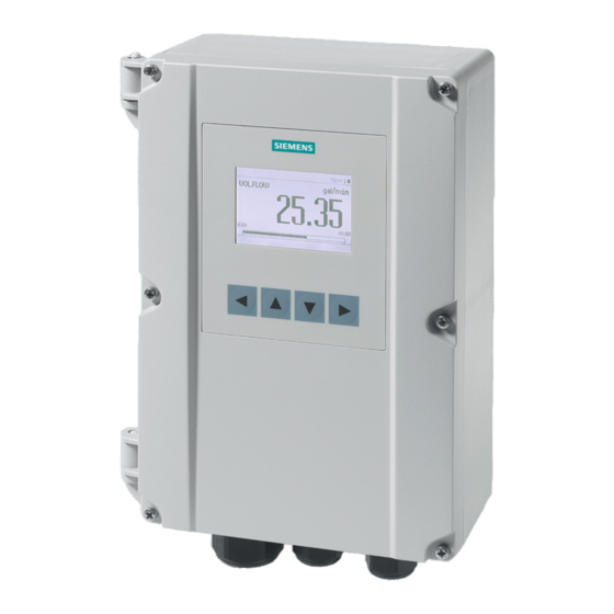
SITRANS F
Ultrasonic Flowmeters
FST020 IP65 NEMA 4X
Operating Instructions
09/2017
A5E41425845-AB
Introduction
Safety notes
Description
Installing/mounting
Connecting
Commissioning
Operating
Service and maintenance
Diagnosing and
troubleshooting
Technical data
Dimension drawings
Replacement parts
Modbus communication
Certificates and support
SIMATIC PDM
1
2
3
4
5
6
7
8
9
10
11
12
A
B
C
Advertisement
Table of Contents

Related Manuals for Siemens SITRANS F


Summary of Contents for Siemens SITRANS F
- Page 1 Introduction Safety notes Description SITRANS F Installing/mounting Ultrasonic Flowmeters FST020 IP65 NEMA 4X Connecting Commissioning Operating Instructions Operating Service and maintenance Diagnosing and troubleshooting Technical data Dimension drawings Replacement parts Modbus communication Certificates and support SIMATIC PDM 09/2017 A5E41425845-AB...
- Page 2 Note the following: WARNING Siemens products may only be used for the applications described in the catalog and in the relevant technical documentation. If products and components from other manufacturers are used, these must be recommended or approved by Siemens. Proper transport, storage, installation, assembly, commissioning, operation and maintenance are required to ensure that the products operate safely and without any problems.
-
Page 3: Table Of Contents
Table of contents Introduction..............................9 Purpose of this documentation....................9 Product compatibility........................9 Document history........................9 Device documentation package.....................10 Items supplied........................10 Checking the consignment.....................11 Further Information.........................11 Notes on warranty........................12 Safety notes..............................13 Precondition for use.......................13 Warning symbols on the device.....................13 Laws and directives........................13 Conformity with European directives..................14 Lithium batteries........................14 Description..............................15 Overview..........................15... - Page 4 Table of contents Transmitter power supply, communications and I/O connections..........28 5.4.1 Sensor connections........................28 5.4.2 Connecting the power supply....................28 5.4.3 Connecting Inputs/Outputs.....................30 5.4.4 Connection Wiring........................31 5.4.5 Finishing the transmitter connection (wall mount housing)............33 Commissioning............................35 Basic Safety notes.........................35 6.1.1 Hazardous contact voltage.....................35 General requirements......................36 Power-up..........................36 Local display..........................36...
- Page 5 Table of contents Maintenance and repair work....................57 8.3.1 Maintenance...........................57 8.3.2 Service and maintenance information..................58 Return procedure........................59 Disposal..........................59 Diagnosing and troubleshooting.........................61 Introduction..........................61 Device status icons........................61 Fault codes and corrective actions..................62 9.3.1 Alarm messages........................62 Technical data............................65 10.1 Power.............................65 10.2 Inputs.............................65 10.3 Outputs...........................66 10.4 Construction...........................66 10.5...
- Page 6 Table of contents A.9.6.1 Sensor............................90 A.9.6.2 Process values........................108 A.9.6.3 Totalizers..........................112 A.9.6.4 Inputs and outputs........................113 A.9.6.5 Date and time........................126 A.9.6.6 Local display........................127 A.9.6.7 Selectable values dependent on the view type..............137 A.9.6.8 Process value filter masks....................138 A.9.7 Maintenance and diagnostics....................139 A.9.7.1 Identification.........................139 A.9.8 Diagnostic events.........................141 A.9.8.1...
- Page 7 Table of contents C.1.6 Adding device to communication network................178 C.1.7 Configuring a new device.....................179 C.1.8 Wizard - Quick Start via PDM....................180 C.1.9 Wizard - Clamp-On Configuration..................181 C.1.10 Wizard - Zero point adjustment....................181 C.1.11 Changing parameter settings using SIMATIC PDM.............182 C.1.12 Parameters accessed via drop-down menus...............183 C.1.13 Process variables.........................184...
- Page 8 Table of contents FST020 IP65 NEMA 4X Operating Instructions, 09/2017, A5E41425845-AB...
-
Page 9: Introduction
Introduction Purpose of this documentation These instructions contain all information required to commission and use the device. Read the instructions carefully prior to installation and commissioning. In order to use the device correctly, first review its principle of operation. The instructions are aimed at persons mechanically installing the device, connecting it electronically, configuring the parameters and commissioning it, as well as service and maintenance engineers. -
Page 10: Device Documentation Package
Items supplied The device is delivered as: Wall mount enclosure ● FST020 transmitter wall mount enclosure ● Siemens Process Instrumentation disk containing certificates and manuals. Note Supplementary information Supplementary product and production specific certificates are included on the SensorFlash ®... -
Page 11: Checking The Consignment
Product information on the Internet The Operating Instructions are available on the documentation disk shipped with the device, and on the Internet on the Siemens homepage, where further information on the range of SITRANS F flowmeters may also be found: Product information on the internet (http://www.siemens.com/flow) -
Page 12: Notes On Warranty
The content reflects the technical status at the time of publishing. Siemens reserves the right to make technical changes in the course of further development. -
Page 13: Safety Notes
Safety notes Precondition for use This device left the factory in good working condition. In order to maintain this status and to ensure safe operation of the device, observe these instructions and all the specifications relevant to safety. Observe the information and symbols on the device. Do not remove any information or symbols from the device. -
Page 14: Conformity With European Directives
Safety notes 2.5 Lithium batteries Conformity with European directives The CE marking on the device symbolizes the conformity with the following European directives: Electromagnetic compatibili‐ Directive of the European Parliament and of the Council on the ty EMC harmonisation of the laws of the Member States relating to elec‐ 2014/30/EU tromagnetic compatibility Low voltage directive LVD... -
Page 15: Description
Description Overview SITRANS FST020 ultrasonic flow meter systems consist of a transmitter and a sensor. The following table lists the available combinations of transmitters and sensors. Transmitter Sensor type FST020 FSS200 family DN 15 to DN 10m (0.5" to 360") Design The transmitter reads the measured process values from the sensor and calculates derived values. -
Page 16: Features
Description 3.3 Features Pipe mount kit The Pipe kit is CQO:1012NMB-1. Figure 3-2 Pipe Mounting shown with mounting plate Features ● Wall mount IP65 enclosure ● Full graphical local display ● SensorFlash (SD card) for memory backup, Datalogger and documentation storage (certificates etc.) ●... - Page 17 ● Simulation of all outputs ● Simulation of alarms ● Enabling alarms for visibility on all outputs (HMI, status and communication) ● Comprehensive diagnostics (Siemens standard) for troubleshooting and sensor checking ● Firmware update ● Data logging in SensorFlash ● Peak indicators ●...
- Page 18 Description 3.3 Features FST020 IP65 NEMA 4X Operating Instructions, 09/2017, A5E41425845-AB...
-
Page 19: Installing/Mounting
Installation instructions (Page 20). Installation location requirements 4.2.1 Environment SITRANS F flowmeters with minimum IP65/NEMA 4X enclosure rating are suitable for indoor and outdoor installations. Process pressure and medium temperature If applicable, make sure that specifications for rated medium temperature (T ) plus ambient temperature that are indicated on the device nameplate / label will not be exceeded. -
Page 20: Normal Environmental Conditions
Installing/mounting 4.3 Installation instructions Sensor Location in piping system The optimum location in the system depends on the presence of excessive gas or air bubbles in the fluid may result in erroneous measurements. Therefore, it is preferred not to install the sensor at the highest point in the system, where gas / air bubbles will be trapped. - Page 21 Installing/mounting 4.3 Installation instructions Prepare holes for the four screws (M6x100 or equivalent). Screw head diameter: max. 13.5 mm; screw shaft diameter: max. 6 mm. ● Recommended mounting: Directly to wall or to electrical cabinet back panel. ● If alternate mounting surface is used it MUST support four times the weight of the unit. Mounting the enclosure 1.
- Page 22 Installing/mounting 4.3 Installation instructions For installation on 2-inch standpipe use the optional CQO:1012NMB pipe mounting kit. Table 4-1 CQO:1012NMB-1 Mounting Kit Description Mounting Plate U-Bolt Assembly including bracket and nuts 8-32 x 5/8 LG cross round head screws #8 Flat washer #8 Split lock washers 8-32 Hex nut 1.
- Page 23 Installing/mounting 4.3 Installation instructions ① Mounting plate ② Stand pipe ③ Mounting hardware (see table above) ④ U-bolt assembly FST020 IP65 NEMA 4X Operating Instructions, 09/2017, A5E41425845-AB...
- Page 24 Installing/mounting 4.3 Installation instructions FST020 IP65 NEMA 4X Operating Instructions, 09/2017, A5E41425845-AB...
-
Page 25: Connecting
Connecting This chapter describes how to wire up the transmitter for operation with a sensor. ● Transmitter power supply, communications and I/O connections (Page 28) ● Sensor connections (Page 28) ● Connecting the power supply (Page 28) ● Connecting Inputs/Outputs (Page 30) ●... -
Page 26: Disconnecting Device
Connecting 5.3 Device nameplates WARNING Mains supply from building installation overvoltage category 2 A circuit breaker (max. 15 A) must be installed in close proximity to the equipment and within easy reach of the operator. It must be marked as the disconnecting device for the equipment. WARNING DC connection devices The DC power source must be isolated from mains supply. -
Page 27: Device Nameplate
Connecting 5.3 Device nameplates 5.3.1 Device nameplate Transmitter nameplates ① Product name Transmitter product name ② System order no. Device-specific system order number (transmitter and sensor) ③ Transmitter order no. Transmitter replacement order numbers ④ Serial no. Transmitter serial number ⑤... -
Page 28: Transmitter Power Supply, Communications And I/O Connections
Connecting 5.4 Transmitter power supply, communications and I/O connections Transmitter power supply, communications and I/O connections 5.4.1 Sensor connections For sensor connection, see the FSS200 Sensor installation instructions manual. 5.4.2 Connecting the power supply Note If the transmitter is not already mounted and cabling has not been run, proceed to Mounting the Transmitter (Page 20) before connecting power. - Page 29 Connecting 5.4 Transmitter power supply, communications and I/O connections 7. Insert AC or DC power wires into wire entry holes and secure by tightening wire clamp screws using a screwdriver. – For AC - Connect ground to terminal and power to terminals L1 and L2N. –...
-
Page 30: Connecting Inputs/Outputs
Connecting 5.4 Transmitter power supply, communications and I/O connections 9. Tighten cable gland. 10.Connect the power cable to the appropriate power source (100-240 VAC @ 50/60 Hz or 11.5-28.5 VDC) and power up unit. WARNING Circuit limited to 15 Amps The branch circuit must be limited to 15A or damage to the unit and death or serious injury may result. -
Page 31: Connection Wiring
Connecting 5.4 Transmitter power supply, communications and I/O connections 5.4.4 Connection Wiring Terminal Block Wiring These connection diagrams apply to the part numbers listed below. SITRANS FST020 FST020 7ME3570..._... Figure 5-4 Terminal board channels and pin numbers Note 4 to 20 mA current output Channel 2 It is not required to use shielded cables for the pure 4 to 20 mA current output. - Page 32 Connecting 5.4 Transmitter power supply, communications and I/O connections Wiring Ω Ω ∗ Ω ① ④ 4 - 20mA output (current source) Digital input (Freeze TOT) ② ⑤ Relay output Digital input (CLR TOT) ③ ⑥ Pulse output Modbus Figure 5-5 Typical FST020 Wiring Isolated 4-20mA Output TB1-1/2 = 250 Ω...
-
Page 33: Finishing The Transmitter Connection (Wall Mount Housing)
Connecting 5.4 Transmitter power supply, communications and I/O connections Pulse output TB1-8 / TB1-9 = +30 VDC max. = 3K Ω minimum Digital Inputs TB1-11 / TB1-12 and TB1-13 / TB1-14 = (10V + 0.02 x RL) max. 2 ≤ Vc ≤ 30 VDC 0 ≤... - Page 34 Connecting 5.4 Transmitter power supply, communications and I/O connections FST020 IP65 NEMA 4X Operating Instructions, 09/2017, A5E41425845-AB...
-
Page 35: Commissioning
Commissioning This chapter gives instructions to commissioning your device, see Commissioning via local display (Page 37). Furthermore, the device can be commissioned using SIMATIC PDM, see Commissioning with PDM (Page 175). Basic Safety notes CAUTION Loss of type of protection Damage to device if the enclosure is open or not properly closed. -
Page 36: General Requirements
Commissioning 6.5 Initial startup General requirements Before commissioning it must be checked that: ● The device has been installed and connected in accordance with the guidelines provided in Installing/mounting (Page 19) and Connecting (Page 25). Power-up Power up the device. Local display will show a screen for initial startup (Page 36). Local display The device is commissioned/operated with the touch keypad on the local display. -
Page 37: Commissioning Via Local Display
Commissioning 6.6 Commissioning via local display You will be asked if you want to start the "Quick commissioning" wizard. If you choose "Yes" (recommended), the "Quick commissioning" wizard will start. If you choose "No", you accept the default values of the device, and the next HMI view will be the operation view 1. Start Language Welcome... -
Page 38: Wizards
Commissioning 6.6 Commissioning via local display 6.6.2 Wizards 6.6.2.1 Quick Commissioning wizard (menu item 1.1) The Quick commissioning wizard will guide you through configuration of parameters essential for your application. You configure parameters essential for your application by selecting the configuration path and sub-wizards appropriate for your application. -
Page 39: Sensor Settings Wizard (Wizard)
Commissioning 6.6 Commissioning via local display 6.6.2.4 Sensor settings wizard (wizard) Sensor settings (1) Units settings Units settings Pipe settings Text Options/Description Unit settings Select "Yes" to configure the display units. Unit settings Set the display units of length, temperature, pressure, kinematic viscosity, and density. - Page 40 Commissioning 6.6 Commissioning via local display Sensor settings (2) Pipe settings Pipe class Pipe size Custom Outer diameter + wall thickness Circumference + wall thickness Pipe circumference Outer pipe diameter Wall thickness Select material Custom Wall sound velocity Liner Liner material Liner settings Disturbed flow Inner pipe roughness...
- Page 41 Commissioning 6.6 Commissioning via local display Liner Select "Yes" to configure the liner material. Select "No" to only configure the Inner pipe roughness. Liner material Select the liner material. Liner settings Set the liner sound velocity and thickness. Disturbed flow Define the type of pipe configuration and the distance to the sensor.
- Page 42 Commissioning 6.6 Commissioning via local display Sensor settings (4) Medium settings Medium settings Custom Process parameters Path settings Text Options/Description Medium settings Select "Yes" to configure the medium. Medium settings Select the process medium. Process parameters Set the expected sound velocity (only available if custom process medium is selected) and the process temperature, pressure, kinetic viscosity, and density.
-
Page 43: Process Values Wizard (Menu Item 1.3)
Commissioning 6.6 Commissioning via local display Sensor settings (5) Path settings Installed paths Save settings Finished Start measurement Path geometry Mounting path 1 Path 1 Text Options/Description Path settings Select "YES" to configure the path(s). Installed paths Select the paths installed. Save settings Moves to the next menu item. -
Page 44: Process Values Wizard (Wizard)
Commissioning 6.6 Commissioning via local display ① Wizard name ② Step name / Parameter name ③ View number / Total views in wizard 6.6.2.6 Process values wizard (wizard) Start Quick start Quick commissioning Sensor settings Process values Prioritize Inputs and outputs 1st process value Copy configuration 2st process value... -
Page 45: Inputs/Outputs Wizard
The exact structure of the operating menu is explained in the Function Manual. All items of the menu structure of the device are identified with a unique number. Level 1 of the menu structure is standardized for all Siemens Process Instrumentation devices and covers the following groups: 1. -
Page 46: Navigating The Menu Structure
Commissioning 6.6 Commissioning via local display 5. Security: Contains parameters which describe all security settings of the device. 6. Language: Parameter for changing the language of the local display. Regardless of the language setting, the term for this parameter is always the English term (Language). ①... -
Page 47: Operating
Operating These Operating Instructions describe the operation via the local display (HMI). The device can also be operated via various software. Display views There are six display views, all fully configurable. Use the and the keys to switch between the operator views, Four different types of views are available: ●... -
Page 48: Operating The Fst020
PIN codes can be changed in Security (5). Note Lost PIN code If the PIN code is lost, provide Siemens customer support with the transmitter serial number (see nameplate). Siemens customer support will provide a code to be entered in PIN recovery (5.3). -
Page 49: Reading The Process Values
Operating 7.3 Operating the FST020 Fixed display text Process value name FLUID TEMP. Medium temperature (Fixed value TOT1 Totalizer 1 Table 7-2 Diagnostic values Fixed display text Diagnostic value name TRN TEMP. Transmitter internal temperature CURR. OUT (CH2) Ch2 value REYNOLDS NO. - Page 50 Operating 7.3 Operating the FST020 Single value Three values 1 value and bargraph Note Bargraphs The bargraph limit values indicate the set lower and upper alarm limits, and the vertical lines in the bargraph indicate the set lower and upper warning limits. 1 value and graph FST020 IP65 NEMA 4X Operating Instructions, 09/2017, A5E41425845-AB...
-
Page 51: Operating The Totalizer
Operating 7.3 Operating the FST020 Six values 7.3.3 Operating the totalizer When totalizer is displayed in the main view, press to access the totalizer operation. Table 7-4 Key functions - totalizer operation Function Exit totalizer operation Select action to perform Select action to perform Perform selected action FST020 IP65 NEMA 4X... -
Page 52: Handling Alarms
Operating 7.3 Operating the FST020 7.3.4 Handling alarms When the alarm list is displayed in the main view, press to get more detailed information about the active alarms. Table 7-5 Key functions - alarms list view Function Exit alarm list view Select the item above in the list;... -
Page 53: Reading The Diagnostic Values
Operating 7.3 Operating the FST020 Alarm acknowledgement There are two ways to have the alarms removed from the alarm list. ● Manual: The alarm remains in the alarm list until the alarm is manually acknowledged (ack.). Before the alarm can be acknowledged, the cause must be eliminated. Press to go to the detailed alarm information. - Page 54 Operating 7.3 Operating the FST020 Edit Editable alphanumeric parameters are displayed as shown here. Table 7-6 Key functions - editing alphanumeric values Function Select the next left position. If the most left position is selected: exit the parameter edit view without confirming the changes.
-
Page 55: Changing The Resolution
Operating 7.3 Operating the FST020 7.3.7.1 Changing the resolution In order to change the resolution of the process value shown in the operation view (for example mass flow), set the decimal places parameter for the selected process value. For example, the decimal places for process value Mass flow is defined in Decimal places. - Page 56 Operating 7.3 Operating the FST020 Function Select the option below. Confirm selected option. Multiselection Table 7-9 Key functions - multiselection of options Function Escape the view without changing the value. Scroll up in the list. If the uppermost position is selected: highlight Save settings. Scroll down in the list.
-
Page 57: Service And Maintenance
8.1.1 Impermissible repair of the device WARNING Impermissible repair of the device ● Repair must be carried out by Siemens authorized personnel only. Recalibration Siemens offers to recalibrate the system. Note For recalibration the transmitter must always be returned with the sensor... -
Page 58: Service And Maintenance Information
Service and maintenance 8.3 Maintenance and repair work An inspection can include check of: ● Ambient conditions ● Seal integrity of the process connections, cable entries, and cover screws ● Reliability of power supply, lightning protection, and grounds ● Coupling compound mating the sensors to the pipe surface 8.3.2 Service and maintenance information Service and maintenance information is information about the condition of the device used for... -
Page 59: Return Procedure
– Number of returned devices/replacement parts – Reason for returning the item(s) ● Decontamination declaration (http://www.siemens.com/sc/declarationofdecontamination) With this declaration you warrant "that the device/replacement part has been carefully cleaned and is free of residues. The device/replacement part does not pose a hazard for humans and the environment."... - Page 60 Service and maintenance 8.5 Disposal FST020 IP65 NEMA 4X Operating Instructions, 09/2017, A5E41425845-AB...
-
Page 61: Diagnosing And Troubleshooting
Diagnostic log. The alarm history log can be reset in Reset log. Characteristics of messages The device provides two types of alarm formats, Siemens standard alarm classes and NAMUR status signals, selected in Status icons. -
Page 62: Fault Codes And Corrective Actions
● Indicate read only parameters Data exchange ● Device is communicating Fault codes and corrective actions 9.3.1 Alarm messages Alarms and system messages support both Siemens standard alarm classes and NAMUR status signals. FST020 IP65 NEMA 4X Operating Instructions, 09/2017, A5E41425845-AB... - Page 63 Diagnosing and troubleshooting 9.3 Fault codes and corrective actions In the following tables the alarm IDs (identification numbers) are listed along with possible causes and directions for corrective action. FST020 IP65 NEMA 4X Operating Instructions, 09/2017, A5E41425845-AB...
- Page 64 Diagnosing and troubleshooting 9.3 Fault codes and corrective actions FST020 IP65 NEMA 4X Operating Instructions, 09/2017, A5E41425845-AB...
-
Page 65: Technical Data
Technical data Note Device specifications Siemens makes every attempt to ensure the accuracy of these specifications but reserves the right to change them at any time. 10.1 Power Table 10-1 Power supply Description Specification Supply voltage ● 100 to 240 V AC +10 / -10%, 47 to 63 Hz ●... -
Page 66: Outputs
Technical data 10.4 Construction 10.3 Outputs Table 10-4 Current output Description Channel 2 Signal range 4 to 20 mA Resolution 0.4 μA Load ● Ex i: <470 Ω (HART ≥ 230 Ω) ● Non-Ex: <770 Ω (HART ≥ 230 Ω) Time constant (adjustable) 0.0 to 100 s Fault current... -
Page 67: Operating Conditions
Mechanical load 18 to 1000 Hz random, 3.17 g RMS, in all directions, to EN/IEC 68-2-36 Torques Table 10-8 Installation torques Description Torque (Nm) Cable gland to housing (Siemens supplied, metric, NPT) 10.5 Operating conditions Table 10-9 Basic conditions Description Specification... -
Page 68: Approvals
Technical data 10.7 SensorFlash Table 10-10 Process medium conditions Description Specification Process medium temperature (T ) (min to max) -50 °C to +200 °C (-58 °F to 492 °F) Process medium viscosity Non-compressible liquids 10.6 Approvals UL 61010-1 3rd Edition CAN/CSA-C22.2 No. 61010-1, 3rd Edition EN61010-1: 2010 10.7 SensorFlash Table 10-11 SensorFlash... -
Page 69: Dimension Drawings
Dimension drawings 11.1 Dimension drawing FST020 IP65 NEMA 4X Operating Instructions, 09/2017, A5E41425845-AB... - Page 70 Dimension drawings 11.1 Dimension drawing FST020 IP65 NEMA 4X Operating Instructions, 09/2017, A5E41425845-AB...
-
Page 71: Replacement Parts
Replacement parts 12.1 AC Transmitter exploded view Replaceable parts ① Enclosure cover w/screws and display - A5E38846901 ② Cover with screws - A5E41693888 for AC power supply / A5E41693889 for DC power supply ③ AC power supply - 7ML18301MD / DC power supply - 7ML18301ME ④... - Page 72 Replacement parts 12.1 AC Transmitter exploded view Note It is recommended that when replacing the transmitter main board or display board ensure to remove original SD-card from transmitter and re-install after new modules have been installed in order to recall site parameters. The following components are not shown: ●...
-
Page 73: Modbus Communication
Modbus communication Modbus addressing model The device allows read/write access to one holding register block. All devices are mapped to this Modbus address space. Modbus communication Table A-1 General Modbus settings Modbus Data type / Parameter Description Default val‐ Value range / Access register Size in... - Page 74 Modbus communication A.2 Modbus communication Modbus Data type / Parameter Description Default val‐ Value range / Access register Size in Setting options level bytes [units] (units register) 8298 Unsigned / Baud rate Baud rate of Modbus interface. 19200 Bit/s ● 0: 9600 Bit/s Read / write ●...
-
Page 75: Coil Configuration
Modbus communication A.3 Coil configuration Coil configuration The device provides 20 coil definitions which can be configured. Table A-2 Coil configuration Modbus Data type / Parameter Description Default value Value range / Access lev‐ register Size in bytes [units] Setting options (units register) 10300 Unsigned / 2 Modbus coil ad‐... -
Page 76: Modbus Register Mapping
Modbus communication A.4 Modbus register mapping Modbus Data type / Parameter Description Default value Value range / Access lev‐ register Size in bytes [units] Setting options (units register) 10307 Unsigned / 4 Modbus coil bit‐ Bit mask which is compared 0 - 4294967295 Read / write mask 2 against the register value... - Page 77 Modbus communication A.4 Modbus register mapping The device provides means to remap 20 Modbus registers. Table A-3 Modbus register mapping Modbus Data type / Parameter Description Default value Value range / Access register Size in [units] Setting op‐ level bytes (units register) tions 10448...
-
Page 78: Integer Byte Order
Modbus communication A.7 Modbus function codes Integer byte order The device is able to adjust the byte order of integer values. Table A-4 Integer byte order Modbus Data type / Parameter Description Default value Value range / Access register Size in [units] Setting op‐... - Page 79 1 byte Sensor device type 0: SITRANS FC Run indicator 1 byte 255: Running Manufacturer name 12 bytes SIEMENS Product name 32 bytes SITRANS F Product firmware 16 bytes version 2 bytes FST020 IP65 NEMA 4X Operating Instructions, 09/2017, A5E41425845-AB...
-
Page 80: Access Control
Modbus communication A.9 Modbus holding register tables Access control Access control manages whether the Modbus master is allowed to modify device parameters. Reading of parameters is always possible. The general access control rules are: ● The Modbus interface has an access level that can be changed by providing PIN information via the Modbus register 8292 (User PIN) or 8293 (Expert PIN). -
Page 81: Process Values
Modbus communication A.9 Modbus holding register tables Note In case of error message "Check if the device is set to CT or SIL Operation mode", please check for the following root causes: - The device is set to CT mode - The device is set to SIL mode - The used Modbus register address is wrong A.9.2... -
Page 82: Totalizers
Modbus communication A.9 Modbus holding register tables Table A-9 IO values Modbus Data type / Parameter Description Default value Value range / Access register Size in bytes [units] Setting options level (units register) 8803 Float / 4 Loop current Calculated current at Read output channel 2 [mA]... - Page 83 Modbus communication A.9 Modbus holding register tables Modbus Data type / Parameter Description Default value Value range / Access register Size in bytes [units] Setting options level (units register) 8319 Unsigned / 2 Totalizer 1 tar‐ Sets the desired mode ●...
-
Page 84: Units
Modbus communication A.9 Modbus holding register tables A.9.4 Units Table A-11 Units settings for values and quantities communicated via Modbus Modbus Data type / Parameter Description Default value Value range / Access register Size in bytes [units] Setting options level (units register) 7500 Unsigned / 2... - Page 85 Modbus communication A.9 Modbus holding register tables Modbus Data type / Parameter Description Default value Value range / Access register Size in bytes [units] Setting options level (units register) ● 171: BBL31/min (1 barrel = 31 US gallons) ● 172: BBL31/h (1 barrel = 31 US gallons ●...
- Page 86 Modbus communication A.9 Modbus holding register tables Modbus Data type / Parameter Description Default value Value range / Access register Size in bytes [units] Setting options level (units register) 7648 Unsigned / 2 Sound velocity Units for ● 20: ft/s (feet per second) Read / units sound ve‐...
- Page 87 Modbus communication A.9 Modbus holding register tables Modbus Data type / Parameter Description Default value Value range / Access register Size in bytes [units] Setting options level (units register) 8564 Unsigned / 2 Acceleration Units for ac‐ ● 171: ft/s² (feet per second Read / units celeration...
- Page 88 Modbus communication A.9 Modbus holding register tables Modbus Data type / Parameter Description Default value Value range / Access register Size in bytes [units] Setting options level (units register) 8470 String / 8 Custom volume User specif‐ -------- Read / flow units string ic string for write...
-
Page 89: Device Reset
Modbus communication A.9 Modbus holding register tables Modbus Data type / Parameter Description Default value Value range / Access register Size in bytes [units] Setting options level (units register) 8492 Float / 4 Custom velocity Conversion Read / units factor factor for write user specif‐... -
Page 90: Setup
Modbus communication A.9 Modbus holding register tables A.9.6 Setup A.9.6.1 Sensor Sensor settings Table A-13 General sensor settings Modbus Data type / Parameter Description Default value Value range / Access register Size in bytes [units] Setting options level (units register) 1801 Unsigned / 2 Flow direction... - Page 91 Modbus communication A.9 Modbus holding register tables Modbus Data type / Parameter Description Default value Value range / Access register Size in bytes [units] Setting options level (units register) 1226 Unsigned / 2 Pipe material Pipe material. ● 0: Unspecified Read / write ●...
- Page 92 Modbus communication A.9 Modbus holding register tables Modbus Data type / Parameter Description Default value Value range / Access register Size in bytes [units] Setting options level (units register) 1227 Unsigned / 2 Liner material Liner material. ● 0: Not applicable Read / write ●...
- Page 93 Modbus communication A.9 Modbus holding register tables Modbus Data type / Parameter Description Default value Value range / Access register Size in bytes [units] Setting options level (units register) 1223 Unsigned / 2 Downstream Compensation for ● 0: Straight run Read / pipe geometry downstream pipe ge‐...
- Page 94 Modbus communication A.9 Modbus holding register tables Sensor settings (clamp-on) Table A-17 Sensor settings Modbus Data type / Parameter Description Default value Value range / Access register Size in bytes [units] Setting options level (units register) 1324 Unsigned / 2 Sensor model Installed sensor Read /...
- Page 95 Modbus communication A.9 Modbus holding register tables Modbus Data type / Parameter Description Default value Value range / Access register Size in bytes [units] Setting options level (units register) 1327 Unsigned / 2 Clamp-on sen‐ Installed sensor ● 0: None selected / Custom Read / sor model size.
- Page 96 Modbus communication A.9 Modbus holding register tables Modbus Data type / Parameter Description Default value Value range / Access register Size in bytes [units] Setting options level (units register) 1314 Float / 4 Sensor phase The velocity at 3695.5 2000.0 - 10000.0 Read / velocity which the wave...
- Page 97 Modbus communication A.9 Modbus holding register tables Modbus Data type / Parameter Description Default value Value range / Access register Size in bytes [units] Setting options level (units register) 1402 Unsigned / 2 Pre amp selec‐ Enable or disable pre- ●...
- Page 98 Modbus communication A.9 Modbus holding register tables Sensor spacing Table A-19 Sensor spacing settings Modbus Data type / Parameter Description Default value Value range / Access register Size in bytes [units] Setting options level (units register) 1426 Unsigned / 2 Recommended Recommended spac‐...
- Page 99 Modbus communication A.9 Modbus holding register tables Path 1 settings Table A-20 Path 1 settings Modbus Data type / Parameter Description Default value Value range / Access register Size in bytes [units] Setting options level (units register) 1450 Float / 4 Sensor frequen‐...
- Page 100 Modbus communication A.9 Modbus holding register tables Auto offset adjustment Table A-22 Auto offset adjustment Modbus Data type / Parameter Description Default value Value range / Access register Size in bytes [units] Setting options level (units register) Unsigned / 2 Perform zero Command Read /...
- Page 101 Modbus communication A.9 Modbus holding register tables Modbus Data type / Parameter Description Default value Value range / Access register Size in bytes [units] Setting options level (units register) Unsigned / 2 Zero adjust pro‐ The pro‐ Read gress gress of the only currently running...
- Page 102 Modbus communication A.9 Modbus holding register tables Multipoint calibration Table A-23 Multipoint calibration Modbus Data type / Parameter Description Default value Value range / Access register Size in bytes [units] Setting options level (units register) 1051 Unsigned / 2 Protect calibra‐ Specifies protection of Read / ●...
- Page 103 Modbus communication A.9 Modbus holding register tables Modbus Data type / Parameter Description Default value Value range / Access register Size in bytes [units] Setting options level (units register) 1064 Unsigned / 2 Calibration ta‐ The register "Multipoint ● 1..20: Transfer Read / ble command calibration status"...
- Page 104 Modbus communication A.9 Modbus holding register tables Modbus Data type / Parameter Description Default value Value range / Access register Size in bytes [units] Setting options level (units register) 1070 Float / 4 Calibration Calibration point 1 for 0.0 - 100000.0 Read / point 1 undirectional flow or...
- Page 105 Modbus communication A.9 Modbus holding register tables Modbus Data type / Parameter Description Default value Value range / Access register Size in bytes [units] Setting options level (units register) 1090 Float / 4 Calibration Calibration point 6 for 0.0 - 100000.0 Read / point 6 undirectional flow or...
- Page 106 Modbus communication A.9 Modbus holding register tables Modbus Data type / Parameter Description Default value Value range / Access register Size in bytes [units] Setting options level (units register) 1110 Float / 4 Calibration Calibration point 11 for 0.0 - 100000.0 Read / point 11 undirectional flow or...
- Page 107 Modbus communication A.9 Modbus holding register tables Modbus Data type / Parameter Description Default value Value range / Access register Size in bytes [units] Setting options level (units register) 1130 Float / 4 Calibration Calibration point 16 for 0.0 - 100000.0 Read / point 16 undirectional flow or...
-
Page 108: Process Values
Modbus communication A.9 Modbus holding register tables A.9.6.2 Process values Volume flow settings Table A-24 Volume flow settings Modbus Data type / Parameter Description Default value Value range / Access register Size in bytes [units] Setting options level (units register) 7510 Float / 4 Low flow cut-off Volume flow limit for... - Page 109 Modbus communication A.9 Modbus holding register tables Modbus Data type / Parameter Description Default value Value range / Access register Size in bytes [units] Setting options level (units register) 7403 Float / 4 Upper warning Exceeding this limit max. mass -max.
- Page 110 Modbus communication A.9 Modbus holding register tables Sound velocity settings Table A-27 Sound velocity settings Modbus Data type / Parameter Description Default value Value range / Access register Size in bytes [units] Setting options level (units register) 7624 Float / 4 Upper alarm Exceeding this limit Max.
- Page 111 Modbus communication A.9 Modbus holding register tables Kinematic viscosity settings Table A-29 Kinematic viscosity settings Modbus Data type / Parameter Description Default value Value range / Access register Size in bytes [units] Setting options level (units register) 7682 Float / 4 Upper alarm Exceeding this limit Max.
-
Page 112: Totalizers
Modbus communication A.9 Modbus holding register tables A.9.6.3 Totalizers Totalizer 1 settings Table A-30 Totalizer 1 settings Modbus Data type / Parameter Description Default value Value range / Access register Size in bytes [units] Setting options level (units register) 8305 Unsigned / 2 Process value Select process value... -
Page 113: Inputs And Outputs
Modbus communication A.9 Modbus holding register tables Modbus Data type / Parameter Description Default value Value range / Access register Size in bytes [units] Setting options level (units register) 8308 Float / 4 Mass upper Exceeding this limit Max. floating Read / warning limit causes a warning when... - Page 114 Modbus communication A.9 Modbus holding register tables Channel 2 current output settings Table A-32 Channel 2 current output settings Modbus Data type / Parameter Description Default value Value range / Access register Size in bytes [units] Setting options level (units register) 8802 Unsigned / 2 Process value...
- Page 115 Modbus communication A.9 Modbus holding register tables Modbus Data type / Parameter Description Default value Value range / Access register Size in bytes [units] Setting options level (units register) 8868 Float / 4 Lower range Lower volume flow val‐ Read / value volume ue that is mapped to write...
- Page 116 Modbus communication A.9 Modbus holding register tables Modbus Data type / Parameter Description Default value Value range / Access register Size in bytes [units] Setting options level (units register) 10002 Float / 4 Lower range Lower velocity value Read / value velocity that is mapped to the [m/s]...
- Page 117 Modbus communication A.9 Modbus holding register tables Modbus Data type / Parameter Description Default value Value range / Access register Size in bytes [units] Setting options level (units register) 10018 Float / 4 Lower range Lower process viscosi‐ Read / value viscosity ty value that is mapped [m²/s]...
- Page 118 Modbus communication A.9 Modbus holding register tables Channel 3 status output settings (relay) Table A-33 Channel 3 status output settings Modbus Data type / Parameter Description Default value Value range / Access register Size in bytes [units] Setting options level (units register) 9141 Unsigned / 2...
- Page 119 Modbus communication A.9 Modbus holding register tables Modbus Data type / Parameter Description Default value Value range / Access register Size in bytes [units] Setting options level (units register) 9150 Unsigned / 4 Alarm items 5 Bit encoded selection Read / of alarm items that im‐...
- Page 120 Modbus communication A.9 Modbus holding register tables Channel 7 discrete input settings Table A-34 Channel 7 discrete input settings Modbus Data type / Parameter Description Default value Value range / Access register Size in bytes [units] Setting options level (units register) 10563 Unsigned / 2 Input leading...
- Page 121 Modbus communication A.9 Modbus holding register tables Channel 4 frequency output settings Table A-37 Channel 4 frequency output settings Modbus Data type / Parameter Description Default value Value range / Access register Size in bytes [units] Setting options level (units register) 9404 Unsigned / 2 Process value...
- Page 122 Modbus communication A.9 Modbus holding register tables Modbus Data type / Parameter Description Default value Value range / Access register Size in bytes [units] Setting options level (units register) 9411 Float / 4 Upper range Upper mass flow value 0.2 • max. Read / value mass flow that is mapped to the...
- Page 123 Modbus communication A.9 Modbus holding register tables Modbus Data type / Parameter Description Default value Value range / Access register Size in bytes [units] Setting options level (units register) 10224 Float / 4 Upper range Upper velocity value Read / value velocity that is mapped to the [m/s]...
- Page 124 Modbus communication A.9 Modbus holding register tables Modbus Data type / Parameter Description Default value Value range / Access register Size in bytes [units] Setting options level (units register) 10240 Float / 4 Upper range Upper process viscosi‐ Read / value viscosity ty value that is mapped [m²/s]...
- Page 125 Modbus communication A.9 Modbus holding register tables Channel 4 pulse output settings Table A-38 Channel 4 pulse output settings Modbus Data type / Parameter Description Default value Value range / Access register Size in bytes [units] Setting options level (units register) 9460 Unsigned / 2 Process value...
-
Page 126: Date And Time
Modbus communication A.9 Modbus holding register tables Modbus Data type / Parameter Description Default value Value range / Access register Size in bytes [units] Setting options level (units register) 7441 Float / 4 Fail-safe value Output value in case of 0.0 - 12500.0 Read / a fault and when Fail-... -
Page 127: Local Display
Modbus communication A.9 Modbus holding register tables Modbus Data type / Parameter Description Default value Value range / Access register Size in bytes [unit] Setting options level (unit register) 6669 Unsigned / 2 Seconds Holds current seconds 0 - 59 Read / after Get time com‐... - Page 128 Unsigned / 2 Status icons Type of alarm icons Order-specif‐ Read / ● 0: Standard shown in local display. write (Siemens) ● 1: NAMUR 6409 Float / 4 Filter time con‐ Damping filter time for 0.0 - 100.0 Read /...
- Page 129 Modbus communication A.9 Modbus holding register tables Modbus Data type / Parameter Description Default value Value range / Access register Size in bytes [unit] Setting options level (unit register) 9020 Unsigned / 2 value Selection of the third See Selectable values Read / value.
- Page 130 Modbus communication A.9 Modbus holding register tables View 2 settings Table A-42 View 2 settings Modbus Data type / Parameter Description Default value Value range / Access register Size in bytes [unit] Setting options level (unit register) 9013 Unsigned / 2 Enable or disa‐...
- Page 131 Modbus communication A.9 Modbus holding register tables Modbus Data type / Parameter Description Default value Value range / Access register Size in bytes [unit] Setting options level (unit register) 8057 Unsigned / 2 Trend log time Scaling of the time axis. ●...
- Page 132 Modbus communication A.9 Modbus holding register tables Modbus Data type / Parameter Description Default value Value range / Access register Size in bytes [unit] Setting options level (unit register) 9026 Unsigned / 2 value Selection of the third See Selectable values Read / value.
- Page 133 Modbus communication A.9 Modbus holding register tables View 4 settings Table A-44 View 4 settings Modbus Data type / Parameter Description Default value Value range / Access register Size in bytes [unit] Setting options level (unit register) 9015 Unsigned / 2 Enable or disa‐...
- Page 134 Modbus communication A.9 Modbus holding register tables Modbus Data type / Parameter Description Default value Value range / Access register Size in bytes [unit] Setting options level (unit register) 8069 Unsigned / 2 Trend log time Scaling of the time axis. ●...
- Page 135 Modbus communication A.9 Modbus holding register tables Modbus Data type / Parameter Description Default value Value range / Access register Size in bytes [unit] Setting options level (unit register) 9032 Unsigned / 2 value Selection of the third See Selectable values Read / value.
- Page 136 Modbus communication A.9 Modbus holding register tables View 6 settings Table A-46 View 6 settings Modbus Data type / Parameter Description Default value Value range / Access register Size in bytes [unit] Setting options level (unit register) 9017 Unsigned / 2 Enable or disa‐...
-
Page 137: Selectable Values Dependent On The View Type
Modbus communication A.9 Modbus holding register tables Modbus Data type / Parameter Description Default value Value range / Access register Size in bytes [unit] Setting options level (unit register) 8081 Unsigned / 2 Trend log time Scaling of the time axis. ●... -
Page 138: Process Value Filter Masks
Modbus communication A.9 Modbus holding register tables Selected view type Setting options Six diagnostic values ● 10: Transmitter internal temperature ● 44: Ch2 value ● 45: Ch3 value ● 46: Ch4 value ● 50: Reynolds number ● 51: RxGain up path 1 ●... -
Page 139: Maintenance And Diagnostics
6592 String / 12 Manufacturer Device manufacturer. SIEMENS Read only 6104 String / 32 Product name Product name. SITRANS F Read only Also shown on the device nameplate. 6020 String / 16 Version Product version according to Read only order. - Page 140 Modbus communication A.9 Modbus holding register tables Modbus Data type / Parameter Description Default value Value range / Access register Size in [unit] Setting op‐ level bytes (unit register) tions 6030 String / 16 Firmware version Product firmware version. Al‐ Read / so shown on the device write...
-
Page 141: Diagnostic Events
Modbus communication A.9 Modbus holding register tables Sensor Table A-52 Sensor Modbus Data type / Parameter Description Default value Value range / Access register Size in bytes [unit] Setting options level (unit register) 4043 String / 20 Sensors serial Serial number of sen‐ Read number path 1 sor set path 1 (clamp-... - Page 142 Modbus communication A.9 Modbus holding register tables Modbus Data type / Parameter Description Default value Value range / Access register Size in bytes [unit] Setting options level (unit register) 6210 Unsigned / 4 Active alarm Bitwise indication of ac‐ Read items 6 tive alarms in alarm only...
- Page 143 Modbus communication A.9 Modbus holding register tables Modbus Data type / Parameter Description Default value Value range / Access register Size in bytes [unit] Setting options level (unit register) 6262 Unsigned / 4 Supported Bitwise indication of Read alarm items 7 supported alarms in only alarm items 7.
- Page 144 Modbus communication A.9 Modbus holding register tables Modbus Data type / Parameter Description Default value Value range / Access register Size in bytes [unit] Setting options level (unit register) 6280 Unsigned / 4 Active alarm Bitwise indication of ac‐ Read / items 8 tive alarms in alarm write...
-
Page 145: Diagnostic Log
Modbus communication A.9 Modbus holding register tables Assign alarm class Table A-57 Assign alarm class Modbus Data type / Parameter Description Default value Value range / Access register Size in bytes [unit] Setting options level (unit register) 6328 Unsigned / 2 Transmitter Defines the mapping of Read /... -
Page 146: Alarm Items
Modbus communication A.9 Modbus holding register tables Modbus Data type / Parameter Description Default value Value range / Access register Size in bytes [unit] Setting options level (unit register) 6624 Unsigned / 2 Alarm ID Alarm ID of the entry Read specified by Entry num‐... - Page 147 Modbus communication A.9 Modbus holding register tables Group Alarm Restrictions Associated alarm class Alarm items 2 Auxiliary input failure (Sensor alarms 2) Unreliable flow measurement Configuration error 2 Alarm items 4 Mass flow above alarm limit (Process alarms 1) Mass flow above warning limit Mass flow below warning limit Mass flow below alarm limit Volume flow above alarm limit...
- Page 148 Modbus communication A.9 Modbus holding register tables Group Alarm Restrictions Associated alarm class Alarm items 6 Mass flow simulated (Simulation alarms) Volume flow simulated Density simulated 4 - 5 Reserved Totalizer 1 simulated Loop current simulated Product firmware incompatible Transmitter FW incompatible Display FW incompatible IO FW incompatible Sensor type incompatible...
- Page 149 Modbus communication A.9 Modbus holding register tables Group Alarm Restrictions Associated alarm class Alarm items 8 Reserved (Process alarms 3) Reserved Reserved Reserved Sound velocity above alarm limit Sound velocity above warning limit Sound velocity below warning limit Sound velocity below alarm limit Flow velocity above alarm limit Flow velocity above warning limit Flow velocity below warning limit...
-
Page 150: Diagnostics
Modbus communication A.9 Modbus holding register tables A.9.9 Diagnostics A.9.9.1 Sensor Sensor diagnostics Table A-60 Sensor diagnostics Modbus Data type / Parameter Description Default value Value range / Access register Size in bytes [unit] Setting options level (unit register) 3302 Unsigned / 4 Frontend total Operating time of fron‐... -
Page 151: Dsl
Modbus communication A.9 Modbus holding register tables Modbus Data type / Parameter Description Default value Value range / Access register Size in bytes [unit] Setting options level (unit register) 3416 Float / 4 Travel time Travel time of down‐ Read down path 1 stream signal only... -
Page 152: Temperature Monitoring
Modbus communication A.9 Modbus holding register tables Modbus Data type / Parameter Description Default value Value range / Access register Size in bytes [unit] Setting options level (unit register) 3804 Unsigned / 4 Low level errors Every bit represents an Read active low level error only... -
Page 153: Inputs And Outputs
Modbus communication A.9 Modbus holding register tables A.9.9.4 Inputs and outputs General Table A-64 General Modbus Data type / Parameter Description Default val‐ Value range / Access register Size in bytes Setting options level [unit] (unit regis‐ ter) 8799 Unsigned / 2 Reset pulse Command to reset Write on‐... - Page 154 Modbus communication A.9 Modbus holding register tables Channel 4 Table A-67 Channel 4 Modbus Data type / Parameter Description Default value Value range / Access register Size in bytes [unit] Setting options level (unit register) 9469 Float / 4 Pulse status Amount done if config‐...
-
Page 155: Peak Values
Modbus communication A.9 Modbus holding register tables A.9.9.5 Peak values Process value 1 Table A-68 Process value 1 Modbus Data type / Parameter Description Default value Value range / Access register Size in bytes [unit] Setting options level (unit register) 11200 Unsigned / 2 Process value... - Page 156 Modbus communication A.9 Modbus holding register tables Process value 2 Table A-69 Process value 2 Modbus Data type / Parameter Description Default value Value range / Access register Size in bytes [unit] Setting options level (unit register) 11201 Unsigned / 2 Process value Process value config‐...
- Page 157 Modbus communication A.9 Modbus holding register tables Process value 3 Table A-70 Process value 3 Modbus Data type / Parameter Description Default value Value range / Access register Size in bytes [unit] Setting options level (unit register) 11202 Unsigned / 2 Process value Process value config‐...
- Page 158 Modbus communication A.9 Modbus holding register tables Process value 4 Table A-71 Process value 4 Modbus Data type / Parameter Description Default value Value range / Access register Size in bytes [unit] Setting options level (unit register) 11203 Unsigned / 2 Process value Process value config‐...
-
Page 159: Characteristics
Modbus communication A.9 Modbus holding register tables A.9.10 Characteristics A.9.10.1 Transmitter Table A-72 Transmitter Modbus Data type / Parameter Description Default value Value range / Access register Size in bytes [unit] Setting options level (unit register) 6500 String / 32 Design 1 Information of design Read... -
Page 160: Sensorflash
Modbus communication A.9 Modbus holding register tables A.9.11 SensorFlash A.9.11.1 SensorFlash Table A-74 SensorFlash Modbus Data type / Parameter Description Default value Value range / Access register Size in bytes [unit] Setting options level (unit register) 6164 Unsigned / 2 Installed Shows status of SD ●... -
Page 161: Data Logging
Modbus communication A.9 Modbus holding register tables Modbus Data type / Parameter Description Default value Value range / Access register Size in bytes [unit] Setting options level (unit register) 6182 Unsigned / 2 Backup Command to overwrite ● 1: Overwrite existing Write on‐... -
Page 162: Simulation
Modbus communication A.9 Modbus holding register tables Modbus Data type / Parameter Description Default value Value range / Access register Size in bytes [unit] Setting options level (unit register) 11404 Unsigned / 2 Register 1 Modbus register that 65535 Read / defines the parameter write to be logged. - Page 163 Modbus communication A.9 Modbus holding register tables Channel 3 output status Table A-77 Channel 3 output status Modbus Data type / Parameter Description Default value Value range / Access register Size in bytes [unit] Setting options level (unit register) 9164 Unsigned / 2 Simulation Enables or disables...
-
Page 164: Process Values
Modbus communication A.9 Modbus holding register tables A.9.12.2 Process values Simulate process values Table A-80 Channel 2 output current Modbus Data type / Parameter Description Default value Value range / Access register Size in bytes [unit] Setting options level (unit register) 2700 Unsigned / 4 Enable simula‐... -
Page 165: Alarms
Modbus communication A.9 Modbus holding register tables A.9.12.3 Alarms Simulate alarms Table A-81 Simulate alarms Modbus Data type / Parameter Description Default value Value range / Access register Size in bytes [unit] Setting options level (unit register) 6229 Unsigned / 2 Simulation Defines mode of alarm Read /... - Page 166 Modbus communication A.9 Modbus holding register tables Modbus Data type / Parameter Description Default value Value range / Access register Size in bytes [unit] Setting options level (unit register) 6244 Unsigned / 4 Alarm items 8 Bitwise enabling of Read / alarms in alarm items 8.
-
Page 167: Audit Trail
Modbus communication A.9 Modbus holding register tables A.9.13 Audit trail A.9.13.1 Operating time Table A-82 Operating time Modbus Data type / Parameter Description Default value Value range / Access register Size in bytes [unit] Setting options level (unit register) 6160 Unsigned / 4 Operating time Operating time of the... - Page 168 Modbus communication A.9 Modbus holding register tables Modbus Data type / Parameter Description Default value Value range / Access register Size in bytes [unit] Setting options level (unit register) 6760 Unsigned / 2 Data type Data type of Modbus ● 0: No entry Read register specified by only...
-
Page 169: Fw Update Change Log
Modbus communication A.9 Modbus holding register tables A.9.13.3 FW update change log Table A-84 FW update change log Modbus Data type / Parameter Description Default value Value range / Access register Size in bytes [unit] Setting options level (unit register) 6900 Unsigned / 2 Newest entry... -
Page 170: Communication
Modbus communication A.9 Modbus holding register tables A.9.14 Communication A.9.14.1 Service channel Table A-85 Service channel Modbus Data type / Parameter Description Default value Value range / Access register Size in bytes [unit] Setting options level (unit register) 9594 Unsigned / 2 USB mode Returns the USB mode. - Page 171 7326 Unsigned / 2 Unique ID code Unique ID code nee‐ Read ded to request a PUK only from Siemens custom‐ er support. 6177 Unsigned / 2 PUK to reset all PINs to Write on‐ default values. FST020 IP65 NEMA 4X...
- Page 172 Modbus communication A.9 Modbus holding register tables FST020 IP65 NEMA 4X Operating Instructions, 09/2017, A5E41425845-AB...
-
Page 173: Certificates And Support
● Information about field service, repairs, spare parts and lots more under Services. Additional Support If you have additional questions about the device, please contact your local Siemens representative and offices at: Support request (http://www.siemens.com/automation/support-request) FST020 IP65 NEMA 4X... -
Page 174: Qr Code Label
Certificates and support B.3 QR code label QR code label A QR code label can be found on the device. With the use of a smart phone, the QR code provides a direct link to a website with information specific to the device, such as manuals, FAQs, certificates, etc. -
Page 175: Simatic Pdm
SIMATIC PDM Commissioning with PDM C.1.1 Introduction SIMATIC PDM is a software package used to commission and maintain process devices. Procedure examples are for FST030. FST020 procedure is similar but screen shots will appear different for FST020 Eectrical Device Description (EDD). SIMATIC PDM is a software package used to commission and maintain process devices. -
Page 176: Initial Setup
1. Close all SIMATIC programs that are open on the PDM PC. 2. Go to the Windows Start menu and select the menu command SIMATIC PDM → Device Integration Manager under the Siemens SIMATIC programs. You must accept the license agreement to be able to use the Device Integration Manager. - Page 177 SIMATIC PDM C.1 Commissioning with PDM See also FS230 product page (www.siemens.com/FS230) FST020 IP65 NEMA 4X Operating Instructions, 09/2017, A5E41425845-AB...
-
Page 178: Adding Device To Communication Network
SIMATIC PDM C.1 Commissioning with PDM C.1.6 Adding device to communication network Before setting the parameters, it is necessary to configure the FS230 project in PDM. 1. Add the device to SIMATIC Modbus network: – Open the project in the process device network view. –... -
Page 179: Configuring A New Device
SIMATIC PDM C.1 Commissioning with PDM – To set the device address, select the inserted Modbus device in the right window and right-click. Select the Object Properties command in the displayed shortcut menu. – Enter the device-specific information (Modbus address 0-247) in the Communication tab of the Properties dialog for the Modbus device. -
Page 180: Wizard - Quick Start Via Pdm
SIMATIC PDM C.1 Commissioning with PDM C.1.8 Wizard - Quick Start via PDM The graphic Quick Start Wizard provides an easy multistep procedure that configures the device for a simple application. Please consult the SIMATIC PDM operating instructions or online help for details on using SIMATIC PDM. -
Page 181: Wizard - Clamp-On Configuration
SIMATIC PDM C.1 Commissioning with PDM C.1.9 Wizard - Clamp-On Configuration Open the menu Device→Wizard→Clamp-On Configuration, and follow the steps. The clamp-on configuration wizard takes the user through the necessary steps to install the sensors to achieve proper operation. C.1.10 Wizard - Zero point adjustment Open the menu Device →... -
Page 182: Changing Parameter Settings Using Simatic Pdm
SIMATIC PDM C.1 Commissioning with PDM C.1.11 Changing parameter settings using SIMATIC PDM Note For a complete list of parameters, see the Function Manual. Clicking on Cancel during an upload from device to SIMATIC PDM will result in some parameters NOT being updated. Many parameters are accessed via the online menus in PDM, see Parameters accessed via drop-down menus for the others. -
Page 183: Parameters Accessed Via Drop-Down Menus
SIMATIC PDM C.1 Commissioning with PDM C.1.12 Parameters accessed via drop-down menus Click on Device, View or Diagnostics to open the associated drop-down menus. Drop-down menus Table C-1 Device menus Device menus Description Communication Path Shows the communication interface (HART modem) Communication (Modbus) Shows the communication interface (Modbus interface) Download to Device... -
Page 184: Process Variables
SIMATIC PDM C.1 Commissioning with PDM Table C-2 View menus View menus Description Process Variables (online dialog) Shows all process values Device Diagnostic (online dialog) Shows all diagnostics information (alarms and advanced diagnostic parameters) Advanced diagnostics Advanced diagnostics provides the user with operational information to assist in determining that the device is func‐... - Page 185 SIMATIC PDM C.1 Commissioning with PDM Trend view Open the menu View → Process variables and click on a Trend view button to monitor the trend of one or all process values available at each tab. FST020 IP65 NEMA 4X Operating Instructions, 09/2017, A5E41425845-AB...
- Page 186 SIMATIC PDM C.1 Commissioning with PDM FST020 IP65 NEMA 4X Operating Instructions, 09/2017, A5E41425845-AB...
-
Page 187: Index
Index Access control, 80 Electrical connection Access management, 170 Safety, 25 Acknowledge events, 144 Enable events, 143 Active events, 141 Alarm classes, overview, 61 Alarm items, 146 Alarm symbols, overview, 61 Float byte order, 78 Assign alarm class, 145 Flow velocity settings, 109 Auto offset adjustment, 100 FW update change log, 169 Certificates, 13... - Page 188 Index General pipe settings, 90 General sensor settings, 90 General settings, 126, 127 Integer byte order, 78 Lithium batteries IO values, 82 Safety, 14 Kinematic viscosity settings, 111 Maintenance & diagnostics, 139 Mass flow settings, 108 Modbus register mapping, 77 Mains supply, 26 Multipoint calibration, 102 Maintenance, 57...
- Page 189 Sensor frontend, 159 SensorFlash, 68, 160 Service, 173 Service channel, 170 Service information, 58 Warning symbols, 13 Siemens standard alarm classes, 61 Wiring, (See Electrical connection) Simulate alarms, 165 SITRANS FST020, 139 FST020 IP65 NEMA 4X Operating Instructions, 09/2017, A5E41425845-AB...
- Page 190 Index FST020 IP65 NEMA 4X Operating Instructions, 09/2017, A5E41425845-AB...