Sony WRR-805A Operating Instructions Manual
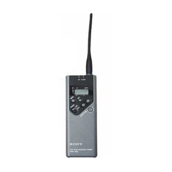
Uhf synthesized portable tuner
Hide thumbs
Also See for WRR-805A:
- Operating instructions manual (94 pages) ,
- Service manual (54 pages)

Related Manuals for Sony WRR-805A


Summary of Contents for Sony WRR-805A
- Page 1 3-866-674-31 (1) UHF Synthesized Portable Tuner Operating Instructions WRR-805A © 1999 by Sony Corporation [AU66]...
-
Page 2: Table Of Contents
Table of Contents Overview ................3 Features ................3 System Configuration ............ 4 Wireless Channels Selectable ........... 4 Precautions ................. 8 Parts Identification ............8 Power Supply ..............11 Settings ................12 Wireless Channel Selection ......... 12 Resetting the Accumulated Time Indication ....14 Connections .............. -
Page 3: Overview
Overview The WRR-805A is a highly reliable portable tuner for the Remote battery alarm from transmitter 800 MHz band Sony UHF wireless microphone system to be This tuner has capability of receiving “Battery status used for broadcast or movie production purposes. -
Page 4: System Configuration
To maintain this, Sony recommends that one of the original Sony groups, number Output monitoring 11, 12, 13, A1, A2, A3, L1, L2, M1, M2, H1 or H2 is The audio output can be monitored through headphones selected. - Page 5 Group 00: All channel access Use to scan for open channels. Use only for a one channel system.
- Page 6 Wireless Channels Selectable Group 11: 12-channel group Group A2: 6-channel group Group 13: 9-channel group Use when both TV channels 66 and 67 Use when TV channel 66 is on the air. Use when TV channel 67 is on the air. are available.
- Page 7 Group M1: 6-channel group Group L1: 6-channel group Group H1: 8-channel group Use when TV channel 67 is on the air. Use when TV channel 67 is on the air. Use when TV channel 66 is on the air. Channel Frequency (MHz) Channel Frequency (MHz)
-
Page 8: Precautions
Precautions Parts Identification • The unit is designed for use in ambient temperature range of 0°C to 50°C (32°F to 122°F). • Do not place the unit on or near heat sources, such as Wire antenna lighting equipment, power amplifiers, or in a place subject to direct sunlight or excessive moisture. - Page 9 1 MONITOR connector B BATT (battery) indication To monitor the audio output signal, connect the headphones Displays the status of the batteries of this unit. equipped with 3.5 mm dia. stereo mini jack. You can use See “Battery indication” on page 11. either of stereo or monaural headphones.
- Page 10 Parts Identification In Accumulated time indication, it displays the accumulated 9 MUTING switch time of battery use (in one-minute increments). Set to ON to eliminate the noise and signal interference See “Settings” on page 12. when the tuner is in signal reception standby mode. See “Muting Functions”...
-
Page 11: Power Supply
Match the polarities and insert the batteries. left in the holder case and the unit may cause poor battery contact. If there seems to be poor battery contact, consult Set the battery holder in the original position. your Sony dealer. -
Page 12: Settings
Settings Press the MODE button until the group name and channel Wireless Channel Selection number appear on the display. Press the SET button. The tuner enters in group selection mode and the group name flashes on the GP section. In group selection mode 3 , 5, 7 RF TX BATT BATT... - Page 13 When no button is pressed for more than 30 seconds, the Once the desired wireless channel is displayed, press the group selection mode or the subsequent wireless channel SET button. selection mode is automatically released. The display stops flashings, and the selected group and Once the desired group indication appears, press the SET wireless channel are stored in memory.
-
Page 14: Resetting The Accumulated Time Indication
If they are inadvertently removed, re- The time indication accumulates time in hours and minutes insert them immediately and repeat the steps on pages 12 when the WRR-805A is on. to 13 from the beginning. Reset the indication to “00:00” whenever you replace the •... -
Page 15: Connections
Connections Microphone System Operation Caution Set the MUTING switch ON before turning on the tuner. When connecting the unit to a camcorder, be sure to turn the unit off. Turn the POWER switch on. Connect the OUTPUT (BAL) connector to the microphone Set the reception channel. -
Page 16: Error Messages
An error occurred in backup memory data. The memory data is initialized. Reset the group and channel settings. ERROR 21 The PLL synthesized circuit is in trouble. Contact your Sony dealer. ERROR 51 Defect of the A/D converter. Contact your Sony dealer. -
Page 17: Use Of The Soft Case
Use of the Soft Case The soft case can be used as shown below. Output cable holder Inserting the unit in reverse direction Detaching the belt clip To microphone While pressing down the shoe MONITOR connector can be input of the on the case 1, pull out the belt used without hindrance. -
Page 18: Specifications
Approx. 170 mA Spurious rejection ratio Battery life Approx. 6 hours of continuous use with 70 dB or more two Sony LR6 batteries at 25°C Image rejection ratio Operating temperature 60 dB or more 0°C to +50°C (32°F to 122°F) Muting level 15 dBµ... - Page 20 Sony Corporation Printed in Japan...