Table of Contents
Advertisement
SCALANCE XC-100
SIMATIC NET
Industrial Ethernet switches
SCALANCE XC-100
Operating Instructions
06/2016
C79000-G8976-C415-02
___________________
Introduction
___________________
Safety notices
___________________
Description of the device
___________________
Mounting
___________________
Connecting up
___________________
Maintenance and
troubleshooting
___________________
Technical specifications
___________________
Certifications and approvals
___________________
Dimension drawings
1
2
3
4
5
6
7
8
9
Advertisement
Table of Contents

Related Manuals for Siemens SCALANCE XC-100


Summary of Contents for Siemens SCALANCE XC-100
- Page 1 ___________________ SCALANCE XC-100 Introduction ___________________ Safety notices ___________________ SIMATIC NET Description of the device ___________________ Mounting Industrial Ethernet switches SCALANCE XC-100 ___________________ Connecting up ___________________ Maintenance and troubleshooting Operating Instructions ___________________ Technical specifications ___________________ Certifications and approvals ___________________ Dimension drawings...
- Page 2 Note the following: WARNING Siemens products may only be used for the applications described in the catalog and in the relevant technical documentation. If products and components from other manufacturers are used, these must be recommended or approved by Siemens. Proper transport, storage, installation, assembly, commissioning, operation and maintenance are required to ensure that the products operate safely and without any problems.
-
Page 3: Table Of Contents
Technical specifications SCALANCE XC106-2 ..............39 Technical specifications of the SCALANCE XC108 ............... 41 Technical specifications of the SCALANCE XC116 ............... 43 Technical specifications of the SCALANCE XC124 ............... 45 Mechanical stability (in operation) ..................46 SCALANCE XC-100 Operating Instructions, 06/2016, C79000-G8976-C415-02... - Page 4 EU declaration of conformity ....................52 8.1.1 ATEX ............................53 8.1.2 EMC ............................53 8.1.3 RoHS ............................54 8.1.4 Products ..........................54 Dimension drawings ..........................55 SCALANCE XC-100 dimension drawings ................55 Index ..............................59 SCALANCE XC-100 Operating Instructions, 06/2016, C79000-G8976-C415-02...
-
Page 5: Introduction
● SCALANCE XC108 ● SCALANCE XC116 ● SCALANCE XC124 Unless mentioned otherwise, the descriptions in these operating instructions refer to all devices of the SCALANCE XC-100 product group named above in the section on validity. Designations used Classification Description Terms used Product line The product line includes all devices and variants of all product groups. - Page 6 You will find the SIMATIC NET glossary on the Internet at the following address: 50305045 (http://support.automation.siemens.com/WW/view/en/50305045) Catalogs You will find the order numbers for the Siemens products of relevance here in the following catalogs: ● SIMATIC NET Industrial Communication / Industrial Identification, catalog IK PI ●...
- Page 7 Siemens recommends strongly that you regularly check for product updates. For the secure operation of Siemens products and solutions, it is necessary to take suitable preventive action (e.g. cell protection concept) and integrate each component into a holistic, state-of-the-art industrial security concept.
- Page 8 • Place the modules only on conductive surfaces. • Pack, store and transport electronic modules and components only in conductive packaging such as metalized plastic or metal containers, conductive foam or household aluminum foil. SCALANCE XC-100 Operating Instructions, 06/2016, C79000-G8976-C415-02...
-
Page 9: Safety Notices
This equipment is suitable for use in Class I, Division 2, Groups A, B, C and D or non- hazardous locations only. This equipment is suitable for use in Class I, Zone 2, Group IIC or non-hazardous locations only. SCALANCE XC-100 Operating Instructions, 06/2016, C79000-G8976-C415-02... - Page 10 Safety notices SCALANCE XC-100 Operating Instructions, 06/2016, C79000-G8976-C415-02...
-
Page 11: Description Of The Device
24 x 10/100 Mbps RJ-45 ports 6GK5 124-0BA00-2AC2 Components of the product The following components are supplied with a SCALANCE XC-100: ● One IE switch ● A 4-pin terminal block for the power supply (spring-loaded terminal) ● A 2-pin terminal block for the signaling contact (spring-loaded terminal) -
Page 12: Device Views
Optical ports ③ Grounding screw ④ Knurled screw ⑤ Securing bar ⑥ Levering aid for moving the securing bar with a screwdriver ⑦ Power supply ⑧ Signaling contact ⑨ "SET" button ⑩ LED display SCALANCE XC-100 Operating Instructions, 06/2016, C79000-G8976-C415-02... -
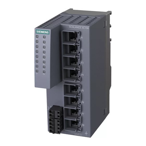
Page 13: Device View Of A Scalance Xc108
Electrical ports ② Grounding screw ③ Knurled screw ④ Securing bar ⑤ Levering aid for moving the securing bar with a screwdriver ⑥ Power supply ⑦ Signaling contact ⑧ "SET" button ⑨ LED display SCALANCE XC-100 Operating Instructions, 06/2016, C79000-G8976-C415-02... -
Page 14: Device View Of A Scalance Xc116
Electrical ports ② Grounding screw ③ Knurled screw ④ Securing bar ⑤ Levering aid for moving the securing bar with a screwdriver ⑥ Power supply ⑦ Signaling contact ⑧ "SET" button ⑨ LED display SCALANCE XC-100 Operating Instructions, 06/2016, C79000-G8976-C415-02... -
Page 15: Device View Of A Scalance Xc124
Electrical ports ② Grounding screw ③ Knurled screw ④ Securing bar ⑤ Levering aid for moving the securing bar with a screwdriver ⑥ Power supply ⑦ Signaling contact ⑧ "SET" button ⑨ LED display SCALANCE XC-100 Operating Instructions, 06/2016, C79000-G8976-C415-02... -
Page 16: Led Display
The port LEDs indicate the status of the ports. LED color LED status Meaning Green Link exists, no data reception at port Yellow Link exists, data reception at port Yellow Flashing Setting or display of the fault mask SCALANCE XC-100 Operating Instructions, 06/2016, C79000-G8976-C415-02... -
Page 17: Set Button
Description of the device 3.4 SET button SET button Position The "SET" button is located on the front of the SCALANCE XC-100. Image 3-1 Position of the "SET" button Function With the SET button, you can display and change the set fault mask. - Page 18 If the link is lost at a monitored port or a monitored power supply is lost, this is signaled as follows: ● the red fault LED lights up ● the signaling contact is opened SCALANCE XC-100 Operating Instructions, 06/2016, C79000-G8976-C415-02...
-
Page 19: Mounting
Replacing components may impair suitability for Class 1, Division 2 or Zone 2. WARNING The device is suitable only for operation in the interior. WARNING The device may only be operated in an environment with pollution degree 1 or 2 (see IEC 60664-1). SCALANCE XC-100 Operating Instructions, 06/2016, C79000-G8976-C415-02... - Page 20 Warming and premature aging of the network component due to direct sunlight Direct sunlight can heat up the device and can lead to premature aging of the network component and its cabling. Provide suitable shade to protect the network component against direct sunlight. SCALANCE XC-100 Operating Instructions, 06/2016, C79000-G8976-C415-02...
-
Page 21: Types Of Installation
Mounting 4.2 Types of installation Types of installation Types of installation The SCALANCE XC-100 can be installed in the following ways: ● DIN rail ● S7-300 standard rail ● S7-1500 standard rail ● Wall mounting Installation clearance Keep to the minimum clearances so that the convection ventilation of the device is not blocked. -
Page 22: Mounting On Din Rails
Mounting on DIN rails Installation Note Note the position of the securing bar, see also section “SCALANCE XC-100 dimension drawings (Page 55)“. When supplied, the securing bar is in the wall mounting position. To change the position of the securing bar, refer to the section “Changing the position of the securing bar (Page 28)“. -
Page 23: Installation On A Standard S7-300 Rail
Installation on a standard S7-300 rail Installing on an S7-300 standard rail Note Note the position of the securing bar, see also section “SCALANCE XC-100 dimension drawings (Page 55)“. When supplied, the securing bar is in the wall mounting position. To change the position of the securing bar, refer to the section “Changing the position of the securing bar (Page 28)“. - Page 24 2. If necessary, loosen the knurled screw with your hand or a screwdriver. 3. Lever the securing bar down using a screwdriver as far as it will go. 4. Remove the device from the mounting rail with the bar pulled. SCALANCE XC-100 Operating Instructions, 06/2016, C79000-G8976-C415-02...
-
Page 25: Installation On A Standard S7-1500 Rail
Installation on a standard S7-1500 rail Installing on an S7-1500 standard rail Note Note the position of the securing bar, see also section “SCALANCE XC-100 dimension drawings (Page 55)“. When supplied, the securing bar is in the wall mounting position. To change the position of the securing bar, refer to the section “Changing the position of the securing bar (Page 28)“. - Page 26 2. If necessary, loosen the knurled screw with your hand or a screwdriver. 3. Lever the securing bar down using a screwdriver as far as it will go. 4. Remove the device from the mounting rail with the bar pulled. SCALANCE XC-100 Operating Instructions, 06/2016, C79000-G8976-C415-02...
-
Page 27: Wall Mounting
4.6 Wall mounting Wall mounting Preparation Note the position of the securing bar, see also section “SCALANCE XC-100 dimension drawings (Page 55)“. When supplied, the securing bar is in the wall mounting position. You do not need to prepare the device any further. -
Page 28: Changing The Position Of The Securing Bar
The securing bar is fixed in the wall mounting position. 5. If applicable remove the pin. Wall mounting position - rail mounting position To move the securing bar from the wall mounting position to the rail mounting position, loosen the knurled screw. SCALANCE XC-100 Operating Instructions, 06/2016, C79000-G8976-C415-02... -
Page 29: Connecting Up
Safety notices on use in hazardous areas General safety notices relating to protection against explosion WARNING EXPLOSION HAZARD Do not connect or disconnect cables to or from the device when a flammable or combustible atmosphere is present. SCALANCE XC-100 Operating Instructions, 06/2016, C79000-G8976-C415-02... - Page 30 Do not connect any electrical connectors directly to the telephone network (telephone network voltage) or a WAN (Wide Area Network). WARNING EXPLOSION HAZARD Do not press the SELECT/SET button when there is an explosive atmosphere. SCALANCE XC-100 Operating Instructions, 06/2016, C79000-G8976-C415-02...
-
Page 31: Wiring Rules
** See note "Wire end ferrules" Note Wire end ferrules Use crimp shapes with smooth surfaces, such as provided by square and trapeze shaped crimp cross sections. Crimp shapes with wave-shaped profile are unsuitable. SCALANCE XC-100 Operating Instructions, 06/2016, C79000-G8976-C415-02... -
Page 32: Power Supply
Dehn Blitzductor BVT AVD 24, article number 918 422 or a comparable protective element. Manufacturer: DEHN+SOEHNE GmbH+Co.KG, Hans-Dehn-Str.1, Postfach 1640, D92306 Neumarkt, Germany Operate the SCALANCE XC-100 with suitable overvoltage protection. Note The device can be disconnected from the power supply with the terminal block. Information on the power supply ●... - Page 33 Connecting up 5.3 Power supply Position and assignment Image 5-1 Position of the power supply on the SCALANCE XC-100 and the assignment of the terminal block Contact Assignment L1+ DC 12 ... 24 V Ground Ground L2+ DC 12 ... 24 V...
-
Page 34: Signaling Contact
The signaling contact can be subjected to a maximum load of 100 mA (safety extra-low voltage SELV, 24 VDC). Higher voltages or currents can damage the device! Position and assignment Image 5-2 Position of the signaling contact on the SCALANCE XC-100 and the assignment of the terminal block Contact Assignment Fault contact 1... - Page 35 ● The signaling contact remains open until one of the following events occurs: – The problem is eliminated. – The current status is entered in the fault mask as the new desired status. SCALANCE XC-100 Operating Instructions, 06/2016, C79000-G8976-C415-02...
-
Page 36: Functional Ground
With automation components, functional ground also ensures interference-free operation of a controller. Via the functional ground, interference currents coupled in via the connecting cables are discharged to ground. SCALANCE XC-100 Operating Instructions, 06/2016, C79000-G8976-C415-02... -
Page 37: Maintenance And Troubleshooting
“far end fault” is detected and no data is forwarded. The port LED is already lit. Device defective If a fault develops, send the device to your SIEMENS service center for repair. Repairs on- site are not possible. - Page 38 Maintenance and troubleshooting SCALANCE XC-100 Operating Instructions, 06/2016, C79000-G8976-C415-02...
-
Page 39: Technical Specifications
9.6 to 31.2 VDC Safe Extra Low Voltage (SELV) Design Terminal block, 4 terminals Properties Implemented redundantly Current consumption At 12 VDC 400 mA at 24 VDC 200 mA Effective power loss 4.8 W Fusing 2.5 A SCALANCE XC-100 Operating Instructions, 06/2016, C79000-G8976-C415-02... - Page 40 Response to spanning tree BPDU Forwarding frames CoS acc. to IEEE 802.1Q QoS priority queues IEEE 802.1Q tags (VLAN ID, priori- transparent forwarding Maximum frame size 1532 bytes Forwarding of PRP frames (Parallel Redundancy Protocol) SCALANCE XC-100 Operating Instructions, 06/2016, C79000-G8976-C415-02...
-
Page 41: Technical Specifications Of The Scalance Xc108
• Installation on a DIN rail • Mounting on an S7-300 standard rail • Mounting on an S7-1500 standard rail • Mean time between failure (MTBF) MTBF (EN/IEC 61709; 40 °C) > 100.24 years SCALANCE XC-100 Operating Instructions, 06/2016, C79000-G8976-C415-02... - Page 42 Response to spanning tree BPDU Forwarding frames CoS acc. to IEEE 802.1Q QoS priority queues IEEE 802.1Q tags (VLAN ID, priority) transparent forwarding Maximum frame size 1532 bytes Forwarding of PRP frames (Parallel Redundancy Protocol) SCALANCE XC-100 Operating Instructions, 06/2016, C79000-G8976-C415-02...
-
Page 43: Technical Specifications Of The Scalance Xc116
• Installation on a DIN rail • Mounting on an S7-300 standard rail • Mounting on an S7-1500 standard rail • Mean time between failure (MTBF) MTBF (EN/IEC 61709; 40 °C) > 73.69 years SCALANCE XC-100 Operating Instructions, 06/2016, C79000-G8976-C415-02... - Page 44 Response to spanning tree BPDU Forwarding frames CoS acc. to IEEE 802.1Q QoS priority queues IEEE 802.1Q tags (VLAN ID, priori- transparent forwarding Maximum frame size 1532 bytes Forwarding of PRP frames (Parallel Redundancy Protocol) SCALANCE XC-100 Operating Instructions, 06/2016, C79000-G8976-C415-02...
-
Page 45: Technical Specifications Of The Scalance Xc124
• Installation on a DIN rail • Mounting on an S7-300 standard rail • Mounting on an S7-1500 standard rail • Mean time between failure (MTBF) MTBF (EN/IEC 61709; 40 °C) > 58.42 years SCALANCE XC-100 Operating Instructions, 06/2016, C79000-G8976-C415-02... -
Page 46: Mechanical Stability (In Operation)
10 - 58 Hz: 0.075 mm 6 shocks per axis 85 - 150 Hz: 1 g 1 octave/min, 20 sweeps SCALANCE XC106-2 ● ● SCALANCE XC108 ● ● SCALANCE XC116 ● ● SCALANCE XC124 ● ● SCALANCE XC-100 Operating Instructions, 06/2016, C79000-G8976-C415-02... -
Page 47: Certifications And Approvals
You can check which of the following approvals have been granted for your product by the markings on the type plate. Current approvals on the Internet You will find the current approvals for the product on the Internet pages of Siemens Industry Online Support (https://support.industry.siemens.com/cs/ww/en/ps/15273/cert). → Entry type "Certificates"... - Page 48 Area". You will find this document • on the data medium that ships with some devices. • on the Internet pages of Siemens Industry Online Support (http://support.automation.siemens.com/WW/view/en). Enter the document identification number C234 as the search term. The SIMATIC NET products meet the requirements of the EC directive 94/9/EC "Equipment and Protective Devices for Use in Potentially Explosive Atmospheres”.
- Page 49 ● CAN/CSA-IEC 61010-2-201 Report no. E85972 cULus Approval for Information Technology Equipment cULus Listed I. T. E. Underwriters Laboratories Inc. complying with ● UL 60950-1 (Information Technology Equipment) ● CSA C22.2 No. 60950-1-03 Report no. E115352 SCALANCE XC-100 Operating Instructions, 06/2016, C79000-G8976-C415-02...
- Page 50 Declaration of the conformity according to the technical regulations of the customs union (TR CU) MSIP 요구사항 - For Korea only A급 기기(업무용 방송통신기자재) 이 기기는 업무용(A급) 전자파 적합기기로서 판매자 또는 사용자는 이 점을 주의하시기 바라며, 가정 외의 지역에서 사용하는것을 목적으로 합니다. SCALANCE XC-100 Operating Instructions, 06/2016, C79000-G8976-C415-02...
- Page 51 ● SCALANCE XC108 SCALANCE XC116 SCALANCE XC124 Image 8-1 FDA and IEC approvals CAUTION Use of controls or adjustments or performance of procedures other than those specified herein may result in hazardous radiation exposure. SCALANCE XC-100 Operating Instructions, 06/2016, C79000-G8976-C415-02...
-
Page 52: Eu Declaration Of Conformity
DE-76181 Karlsruhe Germany You will find the EC declaration of conformity for these products on the Internet pages of Siemens Industry Online Support (https://support.industry.siemens.com/cs/ww/en/ps/15273/cert). The SIMATIC NET products described in these Operating Instructions meet the requirements of the following EC directives: ●... -
Page 53: Atex
EN 61000-6-3 Electromagnetic compatibility (EMC) - Part 6-3: Generic standards - Emission standard for residential, commercial and light-industrial environments. EN 61000-6-4 Electromagnetic compatibility (EMC) - Part 6-4: Generic standards - Emission standard for industrial environments. SCALANCE XC-100 Operating Instructions, 06/2016, C79000-G8976-C415-02... -
Page 54: Rohs
The standards that apply to the product are described in EMC (Page 53) and RoHS (Page 54). Product name Standards SCALANCE XC106-2 1, 2, 4, 6, 7 SCALANCE XC108 1, 2, 4, 6, 7 SCALANCE XC116 1, 2, 4, 6, 7 SCALANCE XC124 1, 2, 4, 6, 7 SCALANCE XC-100 Operating Instructions, 06/2016, C79000-G8976-C415-02... -
Page 55: Dimension Drawings
Dimension drawings SCALANCE XC-100 dimension drawings Note Dimensions are specified in mm. Front view of the SCALANCE XC106-2, SCALANCE XC108 ① Securing bar in the rail mounting position ② Securing bar in the wall mounting position (as supplied). Image 9-1... - Page 56 Dimension drawings 9.1 SCALANCE XC-100 dimension drawings Front view of the SCALANCE XC116, SCALANCE XC124 ① Securing bar in the rail mounting position ② Securing bar in the wall mounting position (as supplied). Image 9-2 Width and height SCALANCE XC-100...
- Page 57 Dimension drawings 9.1 SCALANCE XC-100 dimension drawings Side view of the SCALANCE XC-100 ① Securing bar in the rail mounting position ② Securing bar in the wall mounting position (as supplied). Image 9-3 Depth SCALANCE XC-100 Operating Instructions, 06/2016, C79000-G8976-C415-02...
- Page 58 Dimension drawings 9.1 SCALANCE XC-100 dimension drawings Drilling template for wall mounting Image 9-4 Drilling template SCALANCE XC-100 Operating Instructions, 06/2016, C79000-G8976-C415-02...
-
Page 59: Index
Glossary, 6 S7-300, 23 Grounding, 12, 13, 14, 15, 36 Safety notices Grounding screw, 12, 13, 14, 15 for installation, 19 general, 9 Use in hazardous areas, 9, 19, 29 when connecting up, 29 SCALANCE XC-100 Operating Instructions, 06/2016, C79000-G8976-C415-02... - Page 60 Signaling contact, 11, 12, 13, 14, 15, 34 SIMATIC NET glossary, 6 SIMATIC NET manual, 6 Spare parts, 11 Spring-loaded terminal, 11, 32, 34 Switching properties, 40, 42, 44, 46 System manual, 6, 47 Weight, 40, 41, 43, 45 SCALANCE XC-100 Operating Instructions, 06/2016, C79000-G8976-C415-02...