Advertisement
Quick Links
Installation Instructions
MODEL LIM-1
Loop Isolator Module
OPERATION
The Model LIM-1 Loop Isolator module from Siemens
Industry, Inc., isolates short circuits on MXL and
FireFinder-XLS intelligent device loops. By placing
devices between LIM-1s during installation, a short in
the wiring within that group is disconnected from the
rest of the loop. The remainder of the devices
continue to operate. The LIM-1 operates in both
Class A and Class B circuits.
A yellow LED flashes when a device detects a short
circuit. The LIM-1 then isolates that part of the loop.
When the short is removed, the LIM-1 automatically
restores the loop to normal operation. The LIM-1
does not have a loop address and therefore does not
require address programming nor does it reduce the
loop capacity below 60 (MXL) or 252 (XLS) devices.
ELECTRICAL RATINGS
A
i t c
e v
5
V
D
C
M
o
d
u
e l
C
A
i t c
e v
2
4
V
D
C
M
o
d
u
e l
S
a t
n
d
b
y
2
4
V
D
C
M
o
d
u
e l
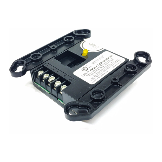
Figure 1
Model LIM-1
Siemens Industry, Inc.
Building Technologies Division
Florham Park, NJ
P/N 315-049552-6
r u
e r
t n
0
m
A
C
r u
e r
t n
7
6
0
u
A
C
r u
e r
t n
7
6
0
u
A
INSTALLATION
Remove all system power before installation, first
the battery and then the AC.
Refer to Figure 1 for the location and number of the
screw terminals on the LIM-1. The LIM-1 has two
input terminals, two output terminals and an earth
ground as listed below:
Terminal Number
1
2
3
4
5
MECHANICAL INSTALLATION (See Figure 2)
1. Use a standard 3
1
/
2
electrical switchbox or a 4-inch square electrical
box that is 2
1
/
inches deep.
8
2. Connect the field wiring. Press the LIM-1 into the
box and fasten the module plate to the box.
3. Cover the module front plate with the plate
supplied and fasten with screws supplied.
4-INCH SQUARE BOX
2 1/8-INCHES DEEP
SWITCHPLATE
5-INCHES SQUARE
(SUPPLIED)
Figure 2
Mounting the LIM-1
Siemens Canada Limited
Building Technologies Division
2 Kenview Boulevard
Brampton, Ontario L6T 5E4 Canada
Description
Loop + IN
Loop - IN
Loop + OUT
Loop - OUT
Earth Ground
-inch deep, double gang
DOUBLE GANG BOX
3 1/2-INCHES DEEP
SWITCHPLATE
5-INCHES SQUARE
(SUPPLIED)
Advertisement

Related Manuals for Siemens LIM-1


Summary of Contents for Siemens LIM-1
-
Page 1: Installation Instructions
Terminal Number Description A yellow LED flashes when a device detects a short Loop + IN circuit. The LIM-1 then isolates that part of the loop. Loop - IN When the short is removed, the LIM-1 automatically Loop + OUT restores the loop to normal operation. - Page 2 2. In order to provide adequate protection, it is recommended Class B (See Figure 3) that you do not install more than 20 devices on a single LIM-1. In Class B wiring each LIM-1 isolates a branch on the 3. Minimum wire gauge is 18 AWG.