Table of Contents
Advertisement
Quick Links
Advertisement
Table of Contents
Troubleshooting

Related Manuals for Philips VLX3


Summary of Contents for Philips VLX3
- Page 2 Please check www.vari-lite.com for latest version. Philips Vari-Lite assumes no responsibility or liability for any errors or inaccuracies that may appear in this manual. All information and graphics are property of Philips Vari- Lite, 10911 Petal Street, Dallas, Texas 75238.
- Page 3 To obtain warranty service, please contact customer service at 1-877-VARI-LITE (1-877-827-4548), +1-214-647-7880, or entertainment.service@philips.com and request a Return Material Authorization (RMA) for warranty service. You will need to provide the model and serial number of the item being returned, a description of the problem or failure and the name of the registered user or organization. If available, you should have your sales invoice to establish the date of sale as the beginning of the warranty period.
- Page 4 ❋ VARI LITE - VLX3 LED W UMINAIRE ERVICE ANUAL Compliance Notice This equipment has been tested and found to comply with the limits for a Class A digital device pursuant to Part 15 of FCC Rules. These limits are designed to provide reasonable protection against harmful interference when this equipment is operated in a commercial environment.
- Page 5 WARNING: INSTRUCTIONS FOR CONTINUED PROTECTION AGAINST FIRE 1. VARI❋LITE luminaires have been designed for use with specific light sources. The VLX3 LED Wash Luminaire uses a special type of LED light source. Installing another type of light source will be hazardous and void the luminaire warranty.
- Page 6 ❋ VARI LITE - VLX3 LED W UMINAIRE ERVICE ANUAL WARNING: INSTRUCTIONS FOR CONTINUED PROTECTION AGAINST EXCESSIVE EXPOSURE TO UV RADIATION 1. Many VARI❋LITE luminaires use a lamp that produces UV radiation. DO NOT look directly at lamp. 2. It is hazardous to operate luminaires without lens or shield. Shields, lenses, or ultraviolet screens shall be changed if they have become visibly damaged to such an extent that their effectiveness is impaired.
- Page 7 HINWEISE ZUM FEUERSCHUTZ 1. VARI❋LITE Beleuchtungen sind für Gebrauch mit spezifischen Lichtquellen bestimmt worden. Die VLX3 LED Wash Luminaire Beleuchtung benutzt eine spezielle Art LED-Lichtquelle. Eine andere Art Lichtquelle anzubringen ist gefährlich und hebt die Beleuchtunggarantie auf. 2. Scheinwerfer können auf jeder beliebigen Oberfläche montiert werden, solange Sie die Montageanweisungen befolgen.
- Page 8 ❋ VARI LITE - VLX3 LED W UMINAIRE ERVICE ANUAL WARNUNG: HINWEISE ZUM SCHUTZ GEGEN ÜBERHÖHTE UV-STRAHLUNG 1. Viele VARI❋LITE -Scheinwerfer verwenden die Lampentyp, der UV-Strahlen abgibt. SCHAUEN SIE NICHT direkt in die Lampe. 2. Es ist gefährlich, Leuchten ohne Linsen oder Blenden zu bedienen. Blenden, Linsen oder Ultraviolettschirme müssen ausgetauscht werden, sofern deren Schutzwirkung durch sichtbare...
- Page 9 1. Des appareils d'éclairage de VARI❋LITE ont été conçus pour l'usage avec des sources lumineuses spécifiques. L'appareil d'éclairage de VLX3 LED Wash Luminaire emploie un type spécial de source lumineuse de LED. L'installation d'un autre type de source lumineuse sera dangereuse et videra la garantie d'appareil d'éclairage.
- Page 10 ❋ VARI LITE - VLX3 LED W UMINAIRE ERVICE ANUAL AVERTISSEMENT: DIRECTIVES POUR SE PROTÉGER CONTRE UNE EXPOSITION EXCESSIVE AUX RAYONS UV 1. Plusieurs luminaires VARI❋LITE utilisent une lampe qui produit des rayons UV. NE PAS fixer son regard sur la lampe.
- Page 11 1. Los alumbrados de VARI❋LITE se han diseñado para el uso con fuentes de luz específicas. El alumbrado de VLX3 LED Wash Luminaire utiliza un tipo especial de fuente de luz del LED. La instalación de otro tipo de fuente de luz será peligrosa y anulará la garantía del alumbrado.
- Page 12 ❋ VARI LITE - VLX3 LED W UMINAIRE ERVICE ANUAL ADVERTENCIA: INSTRUCCIONES PARA PROTECCIÓN CONTINUA CONTRA LA EXPOSICIÓN EXCESIVA DE RADIACIÓN ULTRA VIOLETA 1. Muchas luminarias VARI❋LITE usan un tipo de lámpara que produce radiación UV. NO mire directamente a la lámpara.
- Page 13 OREWORD 02.97 03.001 0 0...
- Page 14 ❋ VARI LITE - VLX3 LED W UMINAIRE ERVICE ANUAL 0 2.9703 .0 010 0...
-
Page 15: Table Of Contents
VLX3 Wash Luminaire Components................6 VLX3 Wash Luminaire Head Components ..............7 VLX3 Wash Enclosure Components ................8 Principles of Operation VLX3 Wash Luminaire Functional Block Diagram ............ 9 Chapter 2. Maintenance Testing Luminaire Self-Tests ....................12 Calibration Sequence ....................12 Sensor Testing ...................... - Page 16 Wireless DMX Interconnect PCB Replacement ............45 Enclosure Fans Replacement..................46 Pan Motor Assembly Replacement ................47 Pan Belt Replacement....................48 VLX3 Wash dropCal (Reinstall Factory LED Calibration) ........50 Chapter 3. Illustrated Parts Breakdown Drawing Tree VLX3 Wash Luminaire ....................54 Top Assembly VLX3 Wash Included Items Kit .................
- Page 17 VLX3 Wash Pan Encoder Cable Assembly............. 104 VLX3 AUX COMM Interface Cable Assembly ............. 105 VLX3 LED Driver Grounds Cable Assembly ............106 VLX3 Yoke to Head Chassis Ground Cable Assembly........... 107 Appendix A. Technical Bulletins and Notices VLX3 Wash Technical Bulletins and Notices............109 02.97 03.001 0 0...
- Page 18 VARI❋LITE - VLX3 LED W UMINAIRE ERVICE ANUAL (This page intentionally blank.) 14 No vemb er 2011 02 .9 703.00 10 0...
-
Page 19: About This Manual
About This Manual This manual provides descriptions, repair procedures, and illustrated parts breakdowns for all configurations of the VLX3 LED Wash Luminaire. The manual is intended for use by Vari-Lite personnel and Authorized VARI❋LITE Service Centers and technicians. WARNING: It is important to read ALL accompanying safety and installation instructions to avoid damage to the product and potential injury to yourself or others. -
Page 20: Customer Service
All technical notices begin with the prefix TN and are numbered sequentially, such as TN-138 (Tech Notice number 138). A list of current technical bulletins and notices associated with VLX Series Luminaires is found in “VLX3 Wash Technical Bulletins and Notices” on page 109. 0 2.9703 .0 010 0... -
Page 21: Chapter 1. Description
HAPTER Description This chapter contains descriptions of luminaire features and components. • Features • Components • Principles of Operation 02.97 03.001 0 0... -
Page 22: Features
Hangs on 21.50 inch (54.6 cm) centers. • Weight is 44 lbs. / 20 kg (luminaire only). Technical Specifications For detailed technical specifications, refer to VLX3 LED Wash Luminaire User’s Manual (02.9701.0001) or the Vari-Lite web site at www.vari-lite.com. 02 .9 703.00 10 0... -
Page 23: Components
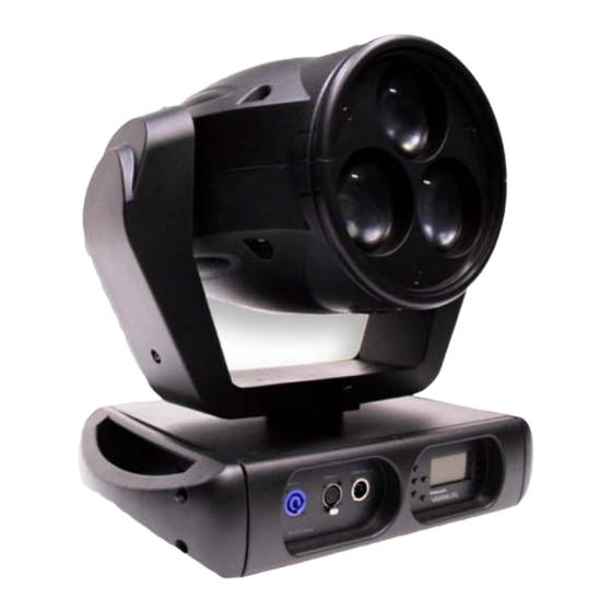
: VLX3 W OMPONENTS XTERNAL OMPONENTS Components VLX3 Wash External Components The following illustration shows the external luminaire components and controls. Upper Enclosure Assembly Houses power supply, pan motor, and display board. Truss Hook Brackets Attaches to enclosure base Menu LCD Display to allow truss hook installation. -
Page 24: Vlx3 Wash Luminaire Components
❋ VARI LITE - VLX3 LED W UMINAIRE ERVICE ANUAL VLX3 Wash Luminaire Components The following illustration shows the major sub-assemblies and components of the luminaire. Luminaire Head Covers Two covers, one on each side of luminaire head assembly. Head Assembly See “VLX3 Wash Luminaire... -
Page 25: Vlx3 Wash Luminaire Head Components
: VLX3 W OMPONENTS UMINAIRE OMPONENTS VLX3 Wash Luminaire Head Components The following illustration shows the major sub-assemblies which are located in the luminaire head assembly. LEDs/LED Cooling Assembly Houses three 120W LEDs and LED cooling assembly. LED Driver PCBs One Driver PCB per LED. -
Page 26: Vlx3 Wash Enclosure Components
❋ VARI LITE - VLX3 LED W UMINAIRE ERVICE ANUAL VLX3 Wash Enclosure Components The following illustration shows the major sub-assemblies which are located in the luminaire enclosure assembly. Wireless DMX Interconnect LCD Display Assembly Allows connection of optional For addressing, accessing wireless DMX module menu options and settings. -
Page 27: Principles Of Operation Vlx3 Wash Luminaire Functional Block Diagram
: VLX3 W RINCIPLES OF PERATION UMINAIRE UNCTIONAL LOCK IAGRAM Principles of Operation VLX3 Wash Luminaire Functional Block Diagram 02.97 03.001 0 0... - Page 28 ❋ VARI LITE - VLX3 LED W UMINAIRE ERVICE ANUAL Notes 02 .9 703.00 10 0...
-
Page 29: Chapter 2. Maintenance
HAPTER Maintenance This chapter contains test, service, and standard maintenance procedures. • Testing • Troubleshooting • Special Care and Handling • Maintenance Procedures WARNING: All maintenance procedures are to be performed with power com- pletely removed from the luminaire. Never remove covers while unit is in oper- ation. -
Page 30: Testing
Most mechanisms within the VLX3 luminaire are equipped with either optical or magnetic sensors. The VLX3 master control board (MCB) has labeled test points for reading DC voltages at each sensor. Testing is best performed with a digital voltmeter for sensor readings or an Oscilloscope for pan/tilt encoder readings. -
Page 31: Troubleshooting Error Messages
ROUBLESHOOTING RROR ESSAGES Troubleshooting Error Messages If a problem occurs during luminaire calibration, at the end of the calibration sequence the Menu Display will cycle through any applicable error message(s), one at a time until the end of the list is reached. -
Page 32: Troubleshooting Guide
❋ VARI LITE - VLX3 LED W UMINAIRE ERVICE ANUAL Troubleshooting Guide If a problem is suspected, try recalibrating the luminaire to prompt an error message. Refer to “Error Messages” on page 13 for more information. The chart below provides possible causes and remedies for each message. - Page 33 Colors (light output) not Color output not match- Calibration turned On or Off... matching from luminaire ing other VLX3 wash fix- - Check fixture calibration setting. Make sure to luminaire tures operating at same calibration is set to same setting (On or Off) as control settings.
-
Page 34: Special Care And Handling
Repeat the cleaning with isopropyl alcohol to eliminate streaks and soap residue. WARNING: Under no circumstances should ammonia-based cleaners, acetone, or other harsh solvents be used on or near the VLX3 LED Wash Luminaire. These types of cleaners or solvents can permanently damage the optics or housings of the fixture. -
Page 35: General Care And Equipment Handling
PC boards which contain batteries. Required Tools for VLX3 Wash Luminaire Service To properly maintain and service VLX3 LED Wash Luminaires, Vari-Lite recommends that the following tools (in addition to the tools recommended during Vari-Lite’s technical training classes) be available to technicians: •... -
Page 36: Maintenance Procedures Moving Zoom Assembly Replacement
Note: Each cover is secured by a safety tether. Locate clip attached to cover and unclip tether. Remove power and Head Cover CAUTION: allow fixture to cool. Zoom Assembly Quart-Turn Dzus Fasteners (x4) Head Cover Figure 2-1: VLX3 Wash Luminaire - Removing Head Covers 02 .9 703.00 10 0... - Page 37 Note: Some components not shown for clarity. PVC Tubing Side Rail Figure 2-2: VLX3 Wash Zoom Assembly Removal Step 4. Carefully slide Zoom Assembly off actuator motor. Step 5. Reassemble in reverse order. Step 6. Power luminaire and test. 02.97 03.001 0 0...
-
Page 38: Main Control Board (Mcb) Replacement
Note: Each cover is secured by a safety tether. Locate clip attached to cover and unclip tether Remove power and CAUTION: allow fixture to cool. Main Control Board (MCB) Head Cover Quart-Turn Dzus Fasteners (x4) Figure 2-3: VLX3 Wash MCB Removal 02 .9 703.00 10 0... - Page 39 Step 4. At MCB assembly, remove assembly by removing six 6-32 x 1/2" PPZ SEMS screws IMPORTANT! Color Calibration must be re-installed using dropCal and Vari-Lite Programming Dongle. See “VLX3 Wash dropCal (Reinstall Factory LED Calibration)” on page 50 for more information and procedure.
-
Page 40: Low Voltage Supply (Lvs)/Led Power Supply Replacement
10-32 x 5/8" PPB Screws (x4) Display Side Handle Upper Enclosure Figure 2-4: VLX3 Wash Luminaire Upper Enclosure Step 3. Remove the inlet exhaust screen. Step 4. Remove two 10-32 x 9/16" PFB screws securing power supply. Step 5. Slide power supply out of enclosure. Note, the power supply is connected to wiring. Do not pull all the way out until wiring is disconnected. - Page 41 (LVS)/LED P AINTENANCE ROCEDURES OLTAGE UPPLY OWER UPPLY EPLACEMENT Step 6. Disconnect wiring: Wiring Wire Description AC Line Input Black, White Earth Ground Green / Yellow 36 VDC Output Orange, Black Enclosure Fan Red, Black (does not matter which wire goes where) 12 VDC Output to Blue - individual Negative 12 VDC LED Drivers...
-
Page 42: Tilt Motor Assembly Replacement
Head Cover Quart-Turn Dzus Fasteners (x4) Figure 2-5: VLX3 Wash Luminaire Head Cover Removal Step 3. At MCB, disconnect wiring at connections J7, J13, and J14 (see Table 2-3 on page 21 more information). Step 4. Disconnect motor power from tilt motor. -
Page 43: Tilt Encoder Assembly Replacement
AINTENANCE ROCEDURES NCODER SSEMBLY EPLACEMENT Tilt Encoder Assembly Replacement Tools: • #2 Phillips screwdriver WARNING: Ensure that power is completely removed (disconnected) from luminaire before attempting any work. To remove tilt encoder assembly: Step 1. Remove power from luminaire and allow unit to completely cool. Step 2. -
Page 44: Tilt Sensor Assembly Replacement
Note: Each cover is secured by a safety tether. Locate clip attached to cover and unclip tether. Remove power and Head Cover CAUTION: allow fixture to cool. Quart-Turn Dzus Fasteners (x4) Head Cover Figure 2-7: VLX3 Wash Luminaire - Removing Head Covers 02 .9 703.00 10 0... - Page 45 Step 3. Remove both yoke covers by removing one 8-32 x 3/8" PPB SEMS screws per cover. Yoke Arm Cover (x2) 8-32 x 3/8" PPB SEMS Screw (x2) Figure 2-8: VLX3 Wash Yoke Arm Cover Removal Step 4. As shown in Figure 2-9, remove tilt lock by removing two 6-32 x 3/16"...
- Page 46 ❋ VARI LITE - VLX3 LED W UMINAIRE ERVICE ANUAL Step 6. Remove six (note, three per side) 8-32 x 3/8" PPB SEMS screws tilt sensor into yoke on each side. Tilt Bearing Assembly Mounting Holes 8-32 x 3/8" PPB SEMS (x3) Note: Drawing exploded for clarity.
-
Page 47: Led Driver Assembly Replacement
Note: Each cover is secured by a safety tether. Locate clip attached to cover and unclip tether. Remove power and Head Cover CAUTION: allow fixture to cool. Quart-Turn Dzus Fasteners (x4) Head Cover Figure 2-11: VLX3 Wash Luminaire - Removing Head Covers 02.97 03.001 0 0... - Page 48 LED Driver Board Note: Components removed and LED Driver Board drawing exploded for clarity. Figure 2-12: VLX3 Wash LED Driver Boards Step 4. To remove LED Driver Board #1: a. Remove MCB (see “Main Control Board (MCB) Replacement” on page 20).
- Page 49 : LED D AINTENANCE ROCEDURES RIVER SSEMBLY EPLACEMENT b. Remove one M4 x 10MM PPZ SEMS screw mounting driver board to +12vdc buss. Note the green ground wires attached. c. Cut any cable ties holding wiring too LED driver board cage. d.
-
Page 50: Motherboard Assembly Replacement
Note: Each cover is secured by a safety tether. Locate clip attached to cover and unclip tether. Remove power and Head Cover CAUTION: allow fixture to cool. Quart-Turn Dzus Fasteners (x4) Head Cover Figure 2-13: VLX3 Wash Luminaire - Removing Head Covers 02 .9 703.00 10 0... - Page 51 AINTENANCE ROCEDURES OTHERBOARD SSEMBLY EPLACEMENT Step 3. At rear, remove three M4 x 10MM PPZ SEMS screws and remove both rear air baffle and exhaust grill. Note, rear air baffle is split (as shown in detail in Figure 2-14). Rear Air Baffle Detail Baffle Split Motherboard Assembly M4 x 10 mm PPZ...
-
Page 52: Light Pipe Replacement
CAUTION: allow fixture to cool. Quart-Turn Dzus Fasteners (x4) Head Cover Figure 2-15: VLX3 Wash Luminaire - Removing Head Covers Step 3. Remove moving zoom assembly (refer to “Moving Zoom Assembly Replacement” on page 18). Step 4. Remove two M4 x 20MM SHC plastic screws and springs mounting Stationary Zoom Lens Assembly and remove. - Page 53 AINTENANCE ROCEDURES IGHT EPLACEMENT WARNING: Note that light pipe must be handled with extreme care and not be damaged. All fingerprints, grease, smudges, etc. must be removed. Any damage to light pipe and it should be replaced with new. Step 5. USING EXTREME CAUTION AND CARE, remove light pipe from tube. Light Pipe / Tube Top Light Seal Stationary Lens Assembly...
-
Page 54: 120W Rgbw Led Assembly Replacement
Note: Each cover is secured by a safety tether. Locate clip attached to cover and unclip tether. Head Cover Remove power and CAUTION: allow fixture to cool. Quart-Turn Dzus Fasteners (x4) Head Cover Figure 2-17: VLX3 Wash Luminaire - Removing Head Covers 02 .9 703.00 10 0... - Page 55 : 120W RGBW LED A AINTENANCE ROCEDURES SSEMBLY EPLACEMENT Step 3. Remove moving zoom assembly (refer to “Moving Zoom Assembly Replacement” on page 18). Step 4. Remove LED Driver Board of LED to be removed and replaced. See “LED Driver Assembly Replacement”...
-
Page 56: Led Cooling Assembly Replacement
CAUTION: allow fixture to cool. Quart-Turn Dzus Fasteners (x4) Head Cover Figure 2-19: VLX3 Wash Luminaire - Removing Head Covers Step 3. Remove moving zoom assembly (refer to “Moving Zoom Assembly Replacement” on page 18). 02 .9 703.00 10 0... - Page 57 : LED C AINTENANCE ROCEDURES OOLING SSEMBLY EPLACEMENT WARNING: Note that light pipe must be handled with extreme care and not be damaged. All fingerprints, grease, smudges, etc. must be removed. Any damage to light pipe and it should be replaced with new.
-
Page 58: Zoom Motor Assembly Replacement
CAUTION: allow fixture to cool. Quart-Turn Dzus Fasteners (x4) Head Cover Figure 2-21: VLX3 Wash Luminaire - Removing Head Covers Step 3. Remove moving zoom assembly (refer to “Moving Zoom Assembly Replacement” on page 18). Step 4. Remove mother board assembly. See “Motherboard Assembly Replacement”... - Page 59 AINTENANCE ROCEDURES OTOR SSEMBLY EPLACEMENT Step 6. Remove Fan Exhaust Chamber by removing six 10-32 x 1/2" PFZ screws, two from each fan and then three M4 x 8MM screws mounting Exhaust Chamber inside. Step 7. Remove cooler standoff and air dam. Step 8.
-
Page 60: Dmx Pcb Assembly Replacement
❋ VARI LITE - VLX3 LED W UMINAIRE ERVICE ANUAL DMX PCB Assembly Replacement Tools: • #2 Phillips screwdriver WARNING: Ensure that power is completely removed (disconnected) from luminaire before attempting any work. To remove DMX PCB assembly: Step 1. Remove power from luminaire and allow unit to completely cool. -
Page 61: Powercon (Ac Input) Assembly Replacement
(AC I AINTENANCE ROCEDURES OWER NPUT SSEMBLY EPLACEMENT PowerCon (AC Input) Assembly Replacement Tools: • #2 Phillips screwdriver WARNING: Ensure that power is completely removed (disconnected) from luminaire before attempting any work. To remove PowerCon (AC input) assembly: Step 1. Remove power from luminaire and allow unit to completely cool. Step 2. -
Page 62: Display Pcb Assembly Replacement
❋ VARI LITE - VLX3 LED W UMINAIRE ERVICE ANUAL Display PCB Assembly Replacement Tools: • #2 Phillips screwdriver WARNING: Ensure that power is completely removed (disconnected) from luminaire before attempting any work. To remove display PCB assembly: Step 1. Remove power from luminaire and allow unit to completely cool. -
Page 63: Wireless Dmx Interconnect Pcb Replacement
DMX I PCB R AINTENANCE ROCEDURES IRELESS NTERCONNECT EPLACEMENT Wireless DMX Interconnect PCB Replacement Tools: • #2 Phillips screwdriver WARNING: Ensure that power is completely removed (disconnected) from luminaire before attempting any work. To remove wireless DMX interconnect PCB assembly: Step 1. -
Page 64: Enclosure Fans Replacement
❋ VARI LITE - VLX3 LED W UMINAIRE ERVICE ANUAL Enclosure Fans Replacement Tools: • #2 Phillips screwdriver WARNING: Ensure that power is completely removed (disconnected) from luminaire before attempting any work. To remove enclosure fans: Step 1. Remove power from luminaire and allow unit to completely cool. -
Page 65: Pan Motor Assembly Replacement
AINTENANCE ROCEDURES OTOR SSEMBLY EPLACEMENT Pan Motor Assembly Replacement Tools: • #2 Phillips screwdriver WARNING: Ensure that power is completely removed (disconnected) from luminaire before attempting any work. To remove pan motor assembly: Step 1. Remove power from luminaire and allow unit to completely cool. Step 2. -
Page 66: Pan Belt Replacement
❋ VARI LITE - VLX3 LED W UMINAIRE ERVICE ANUAL Pan Belt Replacement Tools: • #2 Phillips screwdriver WARNING: Ensure that power is completely removed (disconnected) from luminaire before attempting any work. To remove pan motor assembly: Step 1. Remove power from luminaire and allow unit to completely cool. - Page 67 AINTENANCE ROCEDURES EPLACEMENT Step 8. As shown in Figure 2-30, at pan pulley cover, remove four 8-32 KEPS nuts and remove cover. 8-32 KEPS Nut (x4) Pan Pulley Cover Pan Motor Assembly Pan Belt Pan Pulley Note: Components removed and drawing exploded for clarity.
-
Page 68: Vlx3 Wash Dropcal (Reinstall Factory Led Calibration)
Using a dropCal file from another fixture will load a different calibration scheme and will cause the fixture to be out of calibration. To reinstall the calibration file in a VLX3 Wash Luminaire: Step 1. Power luminaire and allow calibration routine to run. - Page 69 Upper Enclosure DMX / AC Input Panel Figure 2-32: VLX3 Wash DMX / AC Input Panel Step 9. At PC, attach USB Programming Cable to available USB port and at luminaire, using other end of US Programming USB Cable, connect to DMX IN at DMX / AC Input Panel as...
- Page 70 ❋ VARI LITE - VLX3 LED W UMINAIRE ERVICE ANUAL Step 11. Drag .txt file for specific luminaire into dropCal application window as shown in Figure 2- (example, for VLX 67 [67 being the last digits of the serial number], drag file 67.txt into application window).
-
Page 71: Chapter 3. Illustrated Parts Breakdown
HAPTER Illustrated Parts Breakdown This chapter contains illustrated parts breakdowns for all VLX3 LED Wash Luminaire assemblies. • Drawing Tree • Top Assembly • Head Assembly • Enclosure Assembly • Cable Assemblies 02.97 03.001 0 0... -
Page 72: Drawing Tree
Tilt Motor Mount Assembly Right Tilt Tube Assembly 21.9703.0660 Rev C 21.9703.0661 Rev. A Pulley Pinion Assembly Left Tilt Tube Assembly 21.9687.0655 Rev. A 21.9703.0662 Rev. 0 Figure 3-1: VLX3 Wash Luminaire Subassembly Drawing Tree Part 1 02 .9 703.00 10 0... - Page 73 - 12V Driver Board #2 Cable Assembly 25.9703.0007 Rev A Chassis To Yoke Ground Cable Assembly 25.9661.1520 Rev D - 12V Driver Board #3 Cable Assembly 25.9703.0008 Rev A Figure 3-2: VLX3 Wash Luminaire Subassembly Drawing Tree Part 2 02.97 03.001 0 0...
-
Page 74: Top Assembly
UNPACK/QUICK START SHEET, VLX WASH 04.4037.0001 LABEL, 2.5 X .5 BARCODE (not shown) 04.9678.1001 LABEL, GREEN ROHS COMPLIANT (not shown) 04.9703.0003 LABEL, SHIPPING BOX, VLX3 WASH (not shown) 06.9687.0001 SHIPPING FOAM (not shown) 07.5044.0001 BAG, DESICCANT, SHIPPING BOX (not shown) 07.9703.0001 CARDBOARD SHIPPING BOX, VLX WASH (not shown) 08.9703.0001... - Page 75 : VLX3 W SSEMBLY NCLUDED TEMS VLX3 Wash Included Items Kit (continued) (x2) *3-Pole Neutrik PowerCon Locking Connector for AC Input Power. Power input cable must be constructed by user. Figure 3-3: VLX3 Wash Included Items Kit 02.97 03.001 0 0...
-
Page 76: Vlx3 Wash Luminaire
BASE COVER, HANDLE SIDE 21.9703.0010 GENERIC ASSY, VLX3 WASH 21.9703.0611 ASSEMBLY, HEAD COVER, VLX3 WASH 28.9703.0100 INCLUDED ITEMS KIT, VLX3 WASH (NOT SHOWN) 55.6553.0008 SCREW, 10-32 X 9/16" PFB 53.6575.0009 SCREW, 8-32 X 3/8" LG PPB SEMS 53.6627.0001 SCREW, 10-32 X 5/8" PPB 69.9703.0570... - Page 77 : VLX3 W SSEMBLY UMINAIRE VLX3 Wash Luminaire (continued) (x2) (x2) (x6) (x2) (x2) (x2) (x8) Figure 3-4: VLX3 Wash Luminaire 02.97 03.001 0 0...
-
Page 78: Vlx3 Wash Generic Assembly
25.9703.0011 CABLE ASSY, ZOOM (NOT SHOWN) 25.9703.0012 CABLE ASSY, TILT VLX3 WASH (NOT SHOWN) 25.9703.0013 CABLE ASSY, TILT SENSOR, VLX3 WASH (NOT SHOWN) 25.9703.0018 CABLE ASSY, CHASSIS GROUND, YOKE TO HEAD (NOT SHOWN) 53.6543.0003 SCREW, 6-32 X 3/16" PPB 53.6575.0009 SCREW, 8-32 X 3/8"... - Page 79 : VLX3 W SSEMBLY ENERIC SSEMBLY VLX3 Wash Generic Assembly (continued) (x4) (x2) (x6) (x2) (x4) (x6) Figure 3-5: VLX3 Wash Generic Assembly 02.97 03.001 0 0...
-
Page 80: Vlx3 Wash Head Cover Assembly
SCREW, #6 X 1/4" PPZ PLASTIC 55.2233.2003 DZUS RAPIER 1/4-TURN STUD RETAINER, 5 MM 55.2233.2005 DZUS RAPIER 1/4-TURN STUD, 5 MM, 12 MM LG (x2) (x4) (x2) (x4) (x4) Figure 3-6: VLX3 Wash Head Cover Assembly 02 .9 703.00 10 0... -
Page 81: Head Assembly
10.9678.0658 PLATE, COUNTERWEIGHT 10.9678.0672 TETHER, COVER, NYLON COATED 10.9678.0674 BRACKET, COVER TETHER 21.9703.0130 ASSY, ZOOM, MOVING 21.9703.1600 LIGHT ENGINE ASSY, 3 SOURCE LED, VLX3 WASH 21.9703.0650 ASSY, TILT CRADLE 21.9703.0663 ASSY, COVER MOUNT BRACKET (7a) 10.9703.0653 BRACKET, COVER MOUNT (7b) 55.2233.2001... - Page 82 ❋ VARI LITE - VLX3 LED W UMINAIRE ERVICE ANUAL VLX3 Wash Head Assembly (continued) (x4) (x12) (x2) (x2) (x4) See Detail (x18) (x6) Figure 3-1: VLX3 Wash Head Assembly 02 .9 703.00 10 0...
-
Page 83: Moving Zoom Assembly
SSEMBLY OVING SSEMBLY Moving Zoom Assembly 21.9703.0130 Rev A Refer to Figure 3-2 Item Qty. Description 10.9703.0140 LENS RING, FRONT 10.9703.0141 LENS RING, REAR 10.9693.0150 CLAMP, NUT, LINEAR MOTOR 10.9693.0242 BACKING PLATE, ZOOM NUT 10.9693.0740 LINEAR RAIL, LEFT 10.9693.0741 LINEAR RAIL, RIGHT 42.9692.0201 LENS, ASPHERIC, ARCYLIC, TEXTURED 94 MM DIA NUT FOR MOTOR... - Page 84 ❋ VARI LITE - VLX3 LED W UMINAIRE ERVICE ANUAL Moving Zoom Assembly (continued) (x3) (x9) See Note (x2) (x2) (x3) NOTE: *Shown for reference / positioning only. Part of motor in assembly 21.9703.0255. Figure 3-2: Moving Zoom Assembly 02 .9 703.00 10 0...
-
Page 85: Tilt Cradle Assembly
SSEMBLY RADLE SSEMBLY Tilt Cradle Assembly 21.9703.0650 Rev A Refer to Figure 3-3 Item Qty. Description 10.9703.0651 BULKHEAD, TILT CRADLE, FRONT 10.9703.0654 BULKHEAD, TILT CRADLE, REAR 10.9703.0671 MCB MOUNT, RIGHT 10.9703.0672 MCB MOUNT, LEFT 21.9703.0660 TILT MOTOR MOUNT ASSY 21.9703.0661 TILT TUBE ASSY, RIGHT 21.9703.0662 TILT TUBE ASSY, LEFT... - Page 86 ❋ VARI LITE - VLX3 LED W UMINAIRE ERVICE ANUAL Tilt Cradle Assembly (continued) (x8) (x8) Figure 3-3: Tilt Cradle Assembly 02 .9 703.00 10 0...
-
Page 87: Right Tilt Tube Assembly
SSEMBLY IGHT SSEMBLY Right Tilt Tube Assembly 21.9703.0661 Rev. A Refer to Figure 3-4. Item Qty. Description 10.9687.0652 BRACKET, SENSOR, TILT HOMING 10.9687.0658 PLATE, HOMING, TILT 10.9687.0659 RETAINER, TILT BEARING 10.9687.0660 TILT STOP 10.9687.0662 TILT TUBE 10.9703.0657 TILT TUBE MOUNT, RIGHT 25.9703.0013 SENSOR SWITCH, SLOTTED OPTICAL 53.6527.0001... -
Page 88: Left Tilt Tube Assembly
❋ VARI LITE - VLX3 LED W UMINAIRE ERVICE ANUAL Left Tilt Tube Assembly 21.9703.0662 Rev. 0 Refer to Figure 3-5. Item Qty. Description 10.9687.0659 RETAINER, TILT BEARING 10.9687.0660 TILT STOP 10.9687.0662 TILT TUBE 10.9703.0656 TILT TUBE MOUNT, LEFT 53.6545.0003 SCREW, 8-32 X 3/8"... -
Page 89: Tilt Motor Mount Assembly
SSEMBLY OTOR OUNT SSEMBLY Tilt Motor Mount Assembly 21.9703.0660 Rev C Refer to Figure 3-6 Item Qty. Description 10.9703.0655 MOTOR MOUNT, TILT 21.9687.0655 PULLEY, PINION (INCLUDES ENCODER WHEEL AND SET SCREWS) 24.9703.0690 BRD ASSY, PAN/TILT ENCODER 44.9678.0680 MOTOR, 3 PHASE, SIZE 23 HIGH TORQUE 53.6575.0010 SCREW, 8-32 X 1/2"... - Page 90 ❋ VARI LITE - VLX3 LED W UMINAIRE ERVICE ANUAL Tilt Motor Mount Assembly (continued) (x3) (x2) Drive Pulley Detail & Installation Step 1. Apply one drop of Loctite 603 to motor shaft. 0.379" Step 2. Install drive pulley on motor shaft using twisting motion to insure coverage of shaft with loctite.
-
Page 91: Pulley Pinion Assembly
SSEMBLY ULLEY INION SSEMBLY Pulley Pinion Assembly 21.9687.0655 Rev. A Refer to Figure 3-7. Item Qty. Description 10.9663.8820 CODE WHEEL, 120 COUNT 10.9687.1655 TIMING PULLEY, 18 GROVE, GT2, 6 MM BELT 53.5559.0250 SCREW, SET 6-40 X 0.25" CONE POINT (x2) NOTE: *On item 1, remove backing over adhesive and stick to item 2. -
Page 92: Light Engine (3 Source Led) Assembly
❋ VARI LITE - VLX3 LED W UMINAIRE ERVICE ANUAL Light Engine (3 Source LED) Assembly 21.9703.1600 Rev. C Refer to Figure 3-8. Item Qty. Description 10.9690.0332 TUBE, SHIELD, LIGHT PIPE 10.9690.0341 SEAL, LIGHT PIPE, TOP 10.9693.0345 SIDE RAIL 10.9703.0631 GRILL, AIR EXHAUST, VLX3 WASH 10.9703.0670... - Page 93 (3 S LED) A SSEMBLY IGHT NGINE OURCE SSEMBLY Light Engine (3 Source LED) Assembly (continued) (x3) (2 PL) (x2) (x2) (x2) (x8) (x6) (x8) (x3) (x2) (x4) (x3) (x3) (x6) (x3) (x3) (x6) Figure 3-8: Light Engine (3 Source LED) Assembly 02.97 03.001 0 0...
-
Page 94: Led Engine Cooling Assembly
❋ VARI LITE - VLX3 LED W UMINAIRE ERVICE ANUAL LED Engine Cooling Assembly 21.9693.0310 Rev C Refer to Figure 3-9 Item Qty. Description 10.9690.0333 Z-AXIS STOP, HEX 10.9690.1331 SEAL, Z-AXIS STOP, ULTRA SOFT 10.9693.0340 MOUNTING PLATE, COOLER 10.9693.0341 AIR DAM 10.9693.0342... - Page 95 : LED E SSEMBLY NGINE OOLING SSEMBLY LED Engine Cooling Assembly (continued) (x6) (x3) (x3) (x9) (x3) (x3) (x3) (x3) (x3) (x3) (x3) (x6) (See Torque Note) Torque Note: Torque screws (20) to 80-in oz. using a precision torque wrench. Do not overtighten! Figure 3-9: LED Engine Cooling Assembly 02.97 03.001 0 0...
-
Page 96: Led Driver Board Assembly
❋ VARI LITE - VLX3 LED W UMINAIRE ERVICE ANUAL LED Driver Board Assembly 21.9693.0652 Rev. A Refer to Figure 3-10. Item Qty. Description 10.9692.0237 EMI SHIELD, BODY 10.9692.0238 EMI SHIELD, LID 10.9693.0650 MOUNTING BRACKET, LED DRIVER 24.9690.0570 BOARD ASSY, LED DRIVER 53.6576.0034... -
Page 97: Zoom Intermediate Plate Assembly
SSEMBLY NTERMEDIATE LATE SSEMBLY Zoom Intermediate Plate Assembly 21.9703.0255 Rev. B Refer to Figure 3-11. Item Qty. Description 10.9693.0250 PLATE, INTERMEDIATE LENS MOUNT 10.9693.0387 SUPPORT PILLAR, INTERMEDIATE PLATE, MACHINED 44.9703.0208 MOTOR, LINEAR ACT, SIZE 17, 105 MM SHAFT 53.6520.0438 SCREW, 4-40 X 7/16" LG PPZ SEMS 55.3306.0006 WASHER, FLAT, 0.375"... - Page 98 ❋ VARI LITE - VLX3 LED W UMINAIRE ERVICE ANUAL Notes 02 .9 703.00 10 0...
-
Page 99: Enclosure Assembly Vlx3 Wash Upper Enclosure Assembly
CABLE ASSY, ENCLOSURE TO YOKE CHASSIS GROUND (NOT SHOWN) 25.9703.0001 CABLE ASSY, AC INPUT 25.9703.0002 CABLE ASSY, APS FAN (NOT SHOWN) 25.9703.0003 CABLE ASSY, DMX I/O COMM (NOT SHOWN) 25.9703.0004 CABLE ASSY, VLX3 DISPLAY LINK (NOT SHOWN) 02.97 03.001 0 0... - Page 100 ERVICE ANUAL Item Qty. Description 25.9703.0005 CABLE ASSY, VLX3 36V SUPPLY (NOT SHOWN) 25.9703.0006 CABLE ASSY, -12V DRIVER BOARD #1 (NOT SHOWN) 25.9703.0007 CABLE ASSY, -12V DRIVER BOARD #2 (NOT SHOWN) 25.9703.0008 CABLE ASSY, -12V DRIVER BOARD #3 (NOT SHOWN) 25.9703.0009...
- Page 101 : VLX3 W NCLOSURE SSEMBLY PPER NCLOSURE SSEMBLY VLX3 Wash Upper Enclosure Assembly (continued) (x4) (x4) (x4) (x4) Part of item (x4) (x6) (x4) (x4) Figure 3-12: VLX3 Wash Upper Enclosure Assembly Part 1 02.97 03.001 0 0...
- Page 102 ❋ VARI LITE - VLX3 LED W UMINAIRE ERVICE ANUAL VLX3 Wash Upper Enclosure Assembly (continued) (x2) (x2) (x10) (x6) (x4) (x4) (x4) (x2) (x4) (x4) Figure 3-13: VLX3 Wash Upper Enclosure Assembly Part 2 02 .9 703.00 10 0...
- Page 103 SSEMBLY VLX3 Wash Upper Enclosure Assembly (continued) (x6) (x4) (x2) (x4) (x4) (x4)* (x6) (x4)* *Note: When installing these items, use thread locker Loctite 271 or equivalent. Figure 3-14: VLX3 Wash Upper Enclosure Assembly Part 3 02.97 03.001 0 0...
-
Page 104: Pan Motor Assembly
❋ VARI LITE - VLX3 LED W UMINAIRE ERVICE ANUAL Pan Motor Assembly 21.9687.0860 Rev. B Refer to Figure 3-15 Item Qty. Description 10.9687.0822 PLATE, PAN MOTOR MOUNT 21.9687.0655 PULLEY, PINION (INCLUDES ENCODER WHEEL AND SET SCREWS) 24.9661.5000 BRD ASSY, PAN/TILT ENCODER 44.9687.1680... - Page 105 NCLOSURE SSEMBLY OTOR SSEMBLY Pan Motor Assembly (continued) (x2) (x4) Drive Pulley Detail & Installation Step 1. Apply one drop of Loctite 603 to motor shaft. Step 2. Install drive pulley on motor shaft using twisting motion to insure coverage of shaft with loctite.
- Page 106 ❋ VARI LITE - VLX3 LED W UMINAIRE ERVICE ANUAL Notes 02 .9 703.00 10 0...
-
Page 107: Cable Assemblies
ABLE SSEMBLIES HASSIS ROUND ABLE SSEMBLY Cable Assemblies Chassis To Yoke Ground Cable Assembly 25.9661.1520 Rev D Refer to Figure 3-16 Figure 3-16: Chassis To Yoke Ground Cable Assembly Cables are only available as complete assemblies. The information contained in this Note: section is for reference only. -
Page 108: Vlx3 Wash Ac Input Cable Assembly
25.9703.0001 Rev A Refer to Figure 3-17 Neutral Line Ground Figure 3-17: VLX3 Wash AC Input Cable Assembly Cables are only available as complete assemblies. The information contained in this Note: section is for reference only. 02 .9 703.00 10 0... -
Page 109: Aps Fan Cable Assembly
APS Fan Cable Assembly 25.9703.0002 Rev B Refer to Figure 3-18 Figure 3-18: VLX3 Wash APS Fan Cable Assembly Cables are only available as complete assemblies. The information contained in this Note: section is for reference only. 02.97 03.001 0 0... -
Page 110: Dmx I/O Cable Assembly
❋ VARI LITE - VLX3 LED W UMINAIRE ERVICE ANUAL DMX I/O Cable Assembly 25.9703.0003 Rev B Refer to Figure 3-19 Figure 3-19: DMX I/O Cable Assembly Cables are only available as complete assemblies. The information contained in this Note: section is for reference only. -
Page 111: Vlx3 Wash Display Link Cable Assembly
VLX3 Wash Display Link Cable Assembly 25.9703.0004 Rev B Refer to Figure 3-20 Figure 3-20: VLX3 Wash Display Link Cable Assembly Cables are only available as complete assemblies. The information contained in this Note: section is for reference only. 02.97 03.001 0 0... -
Page 112: Vlx3 Wash 36Vdc Supply Cable Assembly
VLX3 Wash 36VDC Supply Cable Assembly 25.9703.0005 Rev C Refer to Figure 3-21 Figure 3-21: VLX3 Wash 36VDC Supply Cable Assembly Cables are only available as complete assemblies. The information contained in this Note: section is for reference only. 02 .9 703.00 10 0... -
Page 113: - 12V Driver Board #1 Cable Assembly
: - 12V D #1 C ABLE SSEMBLIES RIVER OARD ABLE SSEMBLY - 12V Driver Board #1 Cable Assembly 25.9703.0006 Rev A Refer to Figure 3-22 Figure 3-22: - 12V Driver Board #1 Cable Assembly Cables are only available as complete assemblies. The information contained in this Note: section is for reference only. -
Page 114: - 12V Driver Board #2 Cable Assembly
❋ VARI LITE - VLX3 LED W UMINAIRE ERVICE ANUAL - 12V Driver Board #2 Cable Assembly 25.9703.0007 Rev A Refer to Figure 3-23 Figure 3-23: - 12V Driver Board #2 Cable Assembly Cables are only available as complete assemblies. The information contained in this Note: section is for reference only. -
Page 115: - 12V Driver Board #3 Cable Assembly
: - 12V D #3 C ABLE SSEMBLIES RIVER OARD ABLE SSEMBLY - 12V Driver Board #3 Cable Assembly 25.9703.0008 Rev A Refer to Figure 3-24 Figure 3-24: - 12V Driver Board #3 Cable Assembly Cables are only available as complete assemblies. The information contained in this Note: section is for reference only. -
Page 116: Led Driver Grounds Cable Assembly
❋ VARI LITE - VLX3 LED W UMINAIRE ERVICE ANUAL LED Driver Grounds Cable Assembly 25.9703.0009 Rev A Refer to Figure 3-25 Figure 3-25: LED Driver Grounds Cable Assembly Cables are only available as complete assemblies. The information contained in this Note: section is for reference only. -
Page 117: Led Drive Cable Assembly
: LED D ABLE SSEMBLIES RIVE ABLE SSEMBLY LED Drive Cable Assembly 25.9703.0010 Rev C Refer to Figure 3-26 Figure 3-26: LED Drive Cable Assembly Cables are only available as complete assemblies. The information contained in this Note: section is for reference only. 02.97 03.001 0 0... -
Page 118: Zoom Cable Assembly
❋ VARI LITE - VLX3 LED W UMINAIRE ERVICE ANUAL Zoom Cable Assembly 25.9703.0011 Rev A Refer to Figure 3-27 VIEWED FROM WIRE SIDE Figure 3-27: Zoom Cable Assembly Cables are only available as complete assemblies. The information contained in this Note: section is for reference only. -
Page 119: Vlx3 Wash Tilt Cable Assembly
VLX3 Wash Tilt Cable Assembly 25.9703.0012 Rev B Refer to Figure 3-28 Figure 3-28: VLX3 Wash Tilt Cable Assembly Cables are only available as complete assemblies. The information contained in this Note: section is for reference only. 02.97 03.001 0 0... -
Page 120: Vlx3 Tilt Sensor Cable Assembly
VLX3 Tilt Sensor Cable Assembly 25.9703.0013 Rev A Refer to Figure 3-29 Figure 3-29: VLX3 Tilt Sensor Cable Assembly Cables are only available as complete assemblies. The information contained in this Note: section is for reference only. 02 .9 703.00 10 0... -
Page 121: Vlx3 Wash Tilt Cable Assembly
VLX3 Wash Tilt Cable Assembly 25.9703.0014 Rev C Refer to Figure 3-30 Figure 3-30: VLX3 Wash Pan Motor Cable Assembly Cables are only available as complete assemblies. The information contained in this Note: section is for reference only. 02.97 03.001 0 0... -
Page 122: Vlx3 Wash Pan Encoder Cable Assembly
VLX3 Wash Pan Encoder Cable Assembly 25.9703.0015 Rev B Refer to Figure 3-31 Figure 3-31: VLX3 Wash Pan Encoder Cable Assembly Cables are only available as complete assemblies. The information contained in this Note: section is for reference only. 02 .9 703.00 10 0... -
Page 123: Vlx3 Aux Comm Interface Cable Assembly
VLX3 AUX COMM Interface Cable Assembly 25.9703.0016 Rev A Refer to Figure 3-32 Figure 3-32: VLX3 AUX COMM Interface Cable Assembly Cables are only available as complete assemblies. The information contained in this Note: section is for reference only. 02.97 03.001 0 0... -
Page 124: Vlx3 Led Driver Grounds Cable Assembly
VLX3 LED Driver Grounds Cable Assembly 25.9703.0017 Rev A Refer to Figure 3-33 27" Figure 3-33: VLX3 LED Driver Grounds Cable Assembly Cables are only available as complete assemblies. The information contained in this Note: section is for reference only. 02 .9 703.00 10 0... -
Page 125: Vlx3 Yoke To Head Chassis Ground Cable Assembly
25.9703.0018 Rev A Refer to Figure 3-34 16" Figure 3-34: VLX3 Yoke to Head Chassis Ground Cable Assembly Cables are only available as complete assemblies. The information contained in this Note: section is for reference only. 02.97 03.001 0 0... - Page 126 ❋ VARI LITE - VLX3 LED W UMINAIRE ERVICE ANUAL Notes 02 .9 703.00 10 0...
-
Page 127: Appendix A. Technical Bulletins And Notices
VLX3 Wash Technical Bulletins and Notices The following table identifies the current technical bulletins and notices associated with the VLX3 Wash Luminaires. These improvements have been incorporated into this manual (where applicable) and are available on the Vari-Lite web site at www.vari-lite.com. Please note that not all bulletins or notices are applicable to all versions of the fixtures included in this manual. - Page 128 VARI❋LITE - VLX3 LED W UMINAIRE ERVICE ANUAL Notes 02 .9 703.00 10 0...
- Page 130 Vari-Lite 10911 Petal Street Dallas, Texas 75238 USA 1.877.VARI-LITE ❋ Fax 1.214.647.8038 www.vari-lite.com Date: 14 November 2011 / Manual Part Number: 02.9703.0010 0 ©2011, Vari-Lite A Philips Group Company. All rights reserved. Printed in the U.S.A.