Advertisement
Quick Links
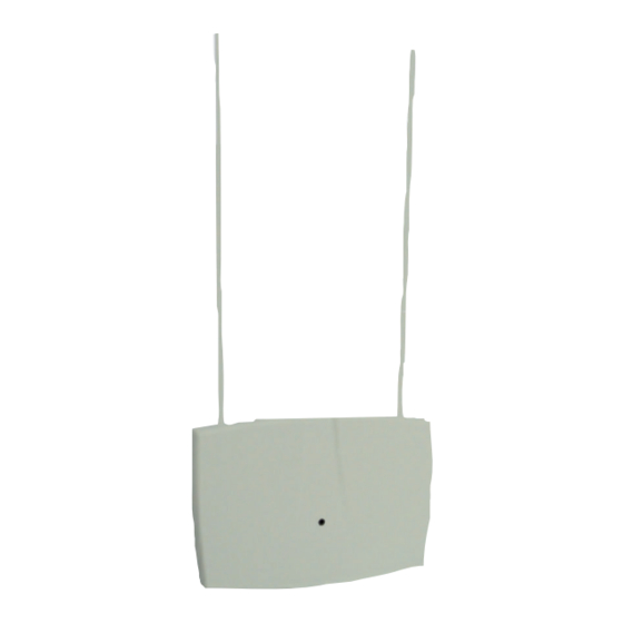
Installation Instructions
RF3222E RF Receiver
1.0 General Information
The RF3222E RF Receiver allows the use of wireless devices when
using the DS7400Xi Control Panel.
2.0 Specifications
• Dimensions (H x W x D):
• Operating Temperature:
• Frequency:
• Power Requirements:
• Compatible Control Panels: DS7400Xi revision 4.03 or
• Compliance: Changes or modifications not expressly approved
by Bosch Security Systems can void the user's authority to operate
the equipment.
3.0 Mounting
3.1
Mounting Considerations
• The receiver should be mounted in a central location in regard to
all wireless sensors, whenever possible.
• The receiver should be mounted on a vertical surface with at
least 25 cm clearance for the antennas.
• Avoid mounting the receiver in areas with significant metal or
electrical wiring, such as furnace rooms and utility rooms. If this
is unavoidable, mount the receiver with the antennas extending
above any metal surface.
• Avoid mounting the receiver in areas where it may be exposed to
moisture.
• Reception distances are generally improved with higher mounting
locations and with no metal objects near the antennas.
3.2
Wall Tamper Setup (Optional)
To enable the wall tamper switch, follow the procedure below. If
use of the wall tamper is not desired, proceed to Section 3.3.
• Remove the outer cover of the receiver (see Figure 1) and set it
aside.
Insert screwdriver here
Figure 1 - Removing the outer cover
• Remove the inner cover (see Figure 2) by pressing the latch.
Figure 2- Removing the inner cover
for the
10.8 cm x 15.2 cm x 3.1 cm
0°C to +65°C
433.42 MHz
12 VDC, 30 mA, nominal
higher.
and press in
Cover Tamper
+
-
+
-
PWR
BUS
ADDR
SUPV
Press Latch
to remove Inner Cover
• Move the wall tamper jumper as shown in Figure 3.
Wall Tamper Jumper
Wall Tamper disabled
(Default Position)
Figure 3 - Wall Tamper Jumper
• Replace the inner cover.
• Place the spring from the hardware packet over the shaft of the
tamper switch located on the back of the receiver (see Figure 4).
Rear of Receiver
Figure 4 - Installing the Tamper Spring
Note: Gently press the spring onto the tapered shaft. Do not force
it down onto the shaft.
3.3
Mounting the Receiver
• Determine the mounting location of the receiver.
Note: Prior to mounting, test the receiver with transmissions from
around the installation to verify reception.
• If not already done, remove the Outer Cover from the Receiver
(see Figure 1) and set it aside.
• Place the receiver base on the wall at the desired mounting
location and mark the two mounting holes (see Figure 5).
Antenna Connectors
Mounting Holes
Cover
Tamper
Switch
Figure 5- Receiver with outer cover removed
• Drill holes and install anchors (supplied) if necessary.
• Secure the receiver base to the wall with screws (supplied).
+
-
+
-
PWR
BUS
ADDR
SUPV
Wall Tamper enabled
Jumper left on pin for storage only.
LED
+
-
+
-
PWR
BUS
ADDR
SUPV
Bus and
Power
Connector
Advertisement

Related Manuals for Bosch RF3222E


Summary of Contents for Bosch RF3222E
- Page 1 Installation Instructions for the Wall Tamper Jumper RF3222E RF Receiver 1.0 General Information ADDR The RF3222E RF Receiver allows the use of wireless devices when SUPV using the DS7400Xi Control Panel. 2.0 Specifications Wall Tamper enabled Wall Tamper disabled • Dimensions (H x W x D): 10.8 cm x 15.2 cm x 3.1 cm...
- Page 2 • Disconnect power to the control panel. • Connect the DS7430 or DS7436 Multiplex Module terminals to the RF3222E receiver’s terminals as shown in Figure 9, using a minimum diameter of 0.8 mm solid wire or 1.0 mm stranded wire.