Table of Contents
Advertisement
Quick Links
Advertisement
Table of Contents

Related Manuals for ABB SREA-01


Summary of Contents for ABB SREA-01
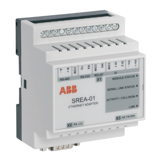
- Page 1 ABB Drives User’s Manual Ethernet Adapter Module SREA-01...
- Page 3 Ethernet Adapter Module SREA-01 User’s Manual 3AUA0000042896 Rev B EFFECTIVE: 30.12.2010 © 2010 ABB Oy. All Rights Reserved.
-
Page 5: Safety Instructions
Overview This chapter states the general safety instructions that must be followed when installing and operating the SREA-01 Ethernet Adapter module. The material in this chapter must be studied before attempting any work on, or with, the unit. In addition to the safety instructions given below, read the complete safety instructions of the specific drive you are working on. - Page 6 Safety instructions...
-
Page 7: Table Of Contents
Providing feedback on ABB Drives manuals ........ - Page 8 System Requirements of ABB IP Configuration Tool ........
- Page 9 Status ............... 55 Modem connection status .
- Page 10 Fault tracing Overview ..............91 Diagnostic LEDs .
-
Page 11: Introduction
Intended audience The manual is intended for the people who are responsible for installing, commissioning and using an SREA-01 Ethernet Adapter module with an ABB drive. The reader is expected to have a basic knowledge of electrical fundamentals, electrical wiring practices, the drive, the use of the drive control panel, internet browsers, and the basic network protocols. -
Page 12: Terms Used In This Manual
Device With SREA-01, the term device is used to refer to a device that is connected to SREA-01, i.e. the drive. DHCP DHCP stands for Dynamic Host Configuration Protocol. It is used in networks to... - Page 13 Internet connection, for example a typical GPRS connection. For more information, see www.dyndns.com. Fault Fault is a serious error condition that prevents the drive from running. SREA-01 can show the reasons for the last drive faults and optionally send alarm messages when a fault condition occurs.
- Page 14 MDI/MDI-X configuration. SREA-01 Ethernet adapter module from hardware revision B supports MDI/MDI-X. Thus in SREA-01 hardware revisions A and B a cross over Ethernet cable is used and in SREA-01 hardware revision C or later a straight Ethernet cable is used.
-
Page 15: Product And Service Inquiries
Product and service inquiries Address any inquiries about the product to your local ABB representative, quoting the type code and serial number of the unit in question. A listing of ABB sales, support and service contacts can be found by navigating to www.abb.com/drives... - Page 16 Introduction...
-
Page 17: Overview
Overview The SREA-01 Ethernet Adapter module SREA-01 is a remote interface device that can connect to 1…10 ABB drives and provide a browser-based service and monitoring interface. The interface provides access to drive parameters, actual values, drive status, faults and data. In addition it has the ability to collect logging data, send alarms and act as a Modbus/TCP gateway. -
Page 18: Delivery Check
The option package for the SREA-01 Ethernet Adapter module contains: • Ethernet Adapter module, type SREA-01 • Ethernet cable for connecting the PC to the SREA-01 for configuration. Straight Ethernet cable can be used permanently for connecting SREA-01 to Ethernet switch or hub. -
Page 19: Quick Start-Up Guide
If you have multiple drives, use the RS-485 connection. Connect the A- channels of the SREA-01 unit and the drives together, the B+ channels together and the COM connector to the data ground connectors of the drives. Use 120 ohm terminating resistors in the network. -
Page 20: Configuration Connection Method 1
The baud rate selection and parity have to be same on all drives and SREA-01. You can use for example 9600 bit/s, no parity, 1 stop bit. For settings and parameter groups, see the drive template guide. -
Page 21: Optional Important Setting Pages
Optional important setting pages For a logging application Setup – Regional Current time settings Setup – Modem Settings for using GSM/GPRS Setup – E-mail E-mail sending options Setup – Users E-mail log recipients Setup – FTP FTP upload settings Configuration – Log What to log and when to send logs For an alarm monitoring unit Setup –... - Page 22 Quick start-up guide...
-
Page 23: Mechanical Installation
Mechanical installation Mounting A – Snap on B – Snap off 1. Choose the location for the module. Note the following: • The cabling instructions in chapter Electrical installation must be followed. • The ambient conditions should be taken into account (see chapter Appendix A: Technical specifications). -
Page 24: Side By Side Mounting
Side by side mounting It is allowed to mount the modules side by side. However, the air outlets of the modules must be kept open so that the cooling air can flow through the modules. The air outlets are shown in the picture below. Air outlets Mechanical installation... -
Page 25: Electrical Installation
Note: Arrange the network and fieldbus cables as far away from the motor cables as possible. Avoid parallel runs. Use bushings at cable entries. Connectors SREA-01 has three connectors: the screw terminal X1, RS-232 connector X2 and Ethernet connector X3. RS-485... - Page 26 The terminal X1 has following pins: RS-485 Negative RS-485 channel Positive RS-485 channel RS-232/RS-485 ground RS-232 RS-232 transmit (RS-232 connector) RS-232 receive (RS-232 connector) RELAY (reserved for future use, not connected) (reserved for future use, not connected) Digital input, common ground Digital input 1 Digital input 2 Vin-...
-
Page 27: Power Supply Connection
SREA-01. Digital inputs SREA-01 has two digital inputs. The inputs can be used to trigger alarms and their status can be shown on custom pages, for example. Their status can also be read by Modbus/TCP by enabling the Internal module registers via Modbus/TCP. - Page 28 Electrical installation...
-
Page 29: Installation Of The Drive Connection
With drives as slaves, SREA-01 can act as Modbus master in a point-to-point RS-232 connection, multi-drop RS-485 connection or in Modbus/TCP connection. In addition SREA-01 can act as a Modbus/TCP gateway that connects to the drives by Modbus RTU and offers access to the drive data by Modbus/TCP. -
Page 30: About The Rs-485 Standard
Termination should be activated on devices located at bus ends and deactivated on other devices. Possible drive interfaces Generally there are four possible ways that the drive can be connected to SREA-01: • Using the panel port, • Using an embedded Modbus connector, •... -
Page 31: Connecting To The Panel Port Of A Single Drive
To make the connection, connect the negative signal connectors to the “RS-485 A-” connector of SREA-01 and the positive signal connectors to the “RS-485 B+” connector. For signal ground, use the COM connector. See the following schematic for more information. - Page 32 … Drive 1 Drive 2 Drive N SREA-01 If you have a dual twisted pair cable, connect both wires of the second twisted pair to ground. The shields of all RS-485 network cables should be connected together. They should be connected to only one device, for example the last drive of the network.
-
Page 33: Changing Network Settings
Note: Changing the network settings of the PC requires administrative privileges. 1. Connect the PC directly to SREA-01 by using an Ethernet cable. 2. Change the IP address of the PC to the same subnet as SREA-01, for example 10.200.1.2. In Microsoft Windows XP, for example, access Network Connections and open the Properties page for your local network adapter. - Page 34 Write down your current network settings. Change the IP address to 10.200.1.2 and the Subnet mask to 255.255.255.0. 3. Open your web browser and enter address http://10.200.1.1. Changing network settings...
- Page 35 Note: Make sure that your browser is not configured to use proxy server for this address. 4. Login in with username admin and password admin: 5. Select Setup – Ethernet from the menu and enter the new network settings. Save the settings when you are finished and reboot the module.
-
Page 36: System Requirements Of Abb Ip Configuration Tool
• Network Interface Card (Ethernet) Installing ABB IP Configuration Tool To install ABB IP Configuration Tool, double click on the ‘IP Configuration Tool Setup.exe’ file on the CD-ROM. The installer starts. Follow the instructions given in the install wizard to finish the installation. -
Page 37: Scanning For Connected Devices
Scanning for connected devices First ensure that you have connected the SREA-01 units you want to install on the same Ethernet network as the PC is connected to. Use standard Ethernet cables, straight-through or crossover cable depending on how you connect to the device. -
Page 38: Changing Ip Settings By Abb Ip Configuration Tool
You can test the new settings by opening a web-browser and entering the IP you assigned to the device. If you selected DHCP and want to know what IP your device have been assigned, you can do a new scan with the ABB IP Configuration Tool to view the new network configuration. -
Page 39: Setting Up Srea-01 For Typical Applications
Setting up SREA-01 for typical applications Overview This chapter explains the most important settings of SREA-01 and how SREA-01 can be configured for the typical applications: data logger application, alarm monitoring application, GPRS access interface application and Modbus/TCP gateway application. For more detailed information on configuring SREA-01, see... -
Page 40: Most Important Common Settings For All Applications
To be able to configure SREA-01 you should enter admin in the username field. The default password is admin. You can later change the default password to something else (recommended). This is described in section Users on page 61. Most important common settings for all applications These settings should be checked in all SREA-01 installations: 1. -
Page 41: Data Logger Application
The regional settings are used for setting the time of the internal real-time clock of the SREA-01 unit. In logging applications this is important because the data is time- stamped by the internal real-time clock. The regional settings can be accessed by selecting Setup –... -
Page 42: Alarm Monitoring Application
By default, there are three alarms defined for each drive. These alarms are sent when the drive is disconnected from SREA-01 and when the drive is in fault or warning state. To enable or disable these alarms or assign them to an alarm class different from 1, go to the page Configuration –... -
Page 43: Modbus/Tcp Gateway Application
Modbus page. • Internal module registers via Modbus/TCP: The Modbus address that can be used to access the internal registers of SREA-01. For example, if you have drives with addresses 1…10 you can set the Internal module registers via Modbus/TCP to 11 and use that address to access the internal registers. - Page 44 • IP Port: The port defined on the Modbus setup page, for example 502 • Unit ID/Node Addresses: The node address of the drive in question. If you want to access the internal registers of SREA-01, use the Internal module registers via Modbus/TCP Address that is defined on the page Setup – Modbus.
-
Page 45: User Interface
User interface Overview This chapter gives instructions on using the web browser interface of SREA-01. The web pages can be used to configure the SREA-01 unit, access information of the drive and control all features of SREA-01. Browser requirements The web pages are optimized for Internet Explorer and Mozilla Firefox. Other browsers can work as well, but the web pages might appear differently. -
Page 46: Menu Overview
The Drive summary page is the default start-up page if there are multiple drives connected to SREA-01. The page shows status and model codes of the drives that are configured and enabled. The page also has links to the sub-pages of each individual drive: the drive information page, the actual values page, the parameters page and the faults page. -
Page 47: Drive Information Page
The page shows the name of the drive, its model, how the drive is connected to SREA-01 and the status of the drive. In addition the page can display additional information text and a drive picture if the user has specified them in the Device configuration. -
Page 48: Actual Values
Actual values The actual values page of a drive can be accessed either by pressing the ‘actual values’ button on the Drive summary page or by selecting Actual values from the sub menu bar when viewing some other page of the drive. Usually the Actual values page shows the groups 1 to 10 of the drive, the command word and the status word. -
Page 49: Real Time Logging Of Parameters
Real time logging of parameters Actual values and parameters can be logged real time. Up to 8 parameters can be logged with cycle time 1 second. Add new parameter for real time logging by clicking the parameter name with the mouse. - Page 50 Note: Real time logging feature is for visual data monitoring and the data is not stored for further analysis or reporting. For more information on zooming the real time data, see section on page 57. User interface...
-
Page 51: Parameters
Parameters The parameters page of a drive can be accessed either by pressing the ‘parameters’ button on the Drive summary page or by selecting Parameters from the sub menu bar when viewing some other page of the drive. The parameters page shows groups 10 to 99 in a similar tree structure as the actual values page shows groups 1 to 10. - Page 52 The upload configuration button can be used to read the complete parameter configuration from the drive to the PC. The parameters are saved in a tab-delimited plain text file. Example of a parameter file: [SREA-01 Report File] 2008-06-02 09:19:19 ACS350 (Scalar) (1)
-
Page 53: Fault Log
01.12: EXTERNAL REF 2 [%] 01.13: CTRL LOCATION EXT1 (1) 01.14: RUN TIME (R) [h] 01.15: KWH COUNTER (R) [kWh]0 01.20: AI 1 [%] Group 03: FB ACTUAL SIGNALS NAME VALUE 03.01: FB CMD WORD 1 12865 03.02: FB CMD WORD 2 8192 03.03: FB STS WORD 1 03.04: FB STS WORD 2... - Page 54 “Online” and “Offline” events. The “Logger started” event is generated every time when the SREA-01 is powered on or a new drive is configured to the SREA-01. A “Drive disconnected” event is generated whenever the drive stops responding to SREA-01 and a “Drive connected”...
-
Page 55: Status
‘clear’ button below the Serial Modbus Status window. The Modbus/TCP messages field shows information about requests that originate from a Modbus/TCP master attached to SREA-01 and that are redirected by the internal Modbus/TCP gateway to the drive interface. Other Modbus messages field shows information about requests that originate from SREA-01, either from internal applications such as Logging and Alarms, or web pages such as the parameter page. -
Page 56: Internal Registers
Connecting to Internet: Calling Internet Service Provider and negotiate for a connection. Waiting for incoming connection: The unit is waiting for an incoming call. Waiting for Event/Alarm: The unit is in standby mode, and when an alarm or event appears it will connect to Internet. -
Page 57: Alarm
For more information about alarm classes, severities and other alarm properties, refer to the section Alarm on page 84. From this page it is possible to download the log file from SREA-01, provided that logging has been enabled. Simply click the ‘download’ button to download/view the User interface... - Page 58 file, or click the ‘clear’ button to remove all data from the log file. To view the log file as a graph, make sure that JAVA is installed on your computer. The graph will show all parameters in the log file, but in the graph it is possible to select which parameters to show (by clicking on the square next to the parameter name).The three first log points will be displayed in the graph.
- Page 59 By using a left click on the mouse, keep the button down and release it at the diagonal corner of a box the graph will zoom to that size. By right clicking and keeping the button down the graph can be scrolled by moving the mouse.
-
Page 60: Setup And Configuration
• web server and page display options, • FTP upload options, • Ethernet network options, such as the IP address. In addition the Setup pages can be used to backup the settings of SREA-01 and to upgrade the firmware. The Configuration pages are used for configuring •... -
Page 61: Setup Pages
• FTP upload options, • Ethernet network options, such as the IP address. In addition the Setup pages can be used to backup the settings of SREA-01 and to upgrade the firmware. Note: The user account must have super admin privileges to be able to access the Setup pages. - Page 62 When clicking the ‘add user’ button or a username, the Modify User page appears. Here you can enter the User ID (used on the login screen), name, contact info and a password. If an E-mail address is entered, then alarms will be sent to this address (if user is configured as an alarm recipient and E-mail alarm is enabled).
-
Page 63: Modbus
Each user can have specific start page for assuring smooth navigation. Select user- specific start page from drop-down menu. Default value of the start page is the default start page of the module. The user level defines what the user can do on the web pages: Read - View pages but can not do any configuration or modify parameters, Write - Can view pages and alter parameters, acknowledge alarms, Admin - Read, Write and also configure the module (templates, devices, pages,... -
Page 64: Serial Settings (Modbus Rtu/Ascii)
Serial Settings (Modbus RTU/ASCII) Transmission mode - Selects Modbus RTU or Modbus ASCII. Modbus RTU is used in all typical drive installations. Slave Response Timeout - The time that the module will wait for a response from the drive, before a Serial timeout will occur (default 1000 ms). Physical Interface - RS-485, RS-232 or RS-232 D-sub. -
Page 65: Internal Registers
IP Authentication - This can be used to configure the IP addresses that are allowed to connect to SREA-01. Connections from other IP addresses will be blocked. Example: You want the SREA-01 to be accessible only from the single IP address 192.168.25.99. Input this IP number to the IP number field and use Mask 255.255.255.255. -
Page 66: Modem
Start by selecting the correct type of modem attached (GSM, Analogue or GPRS). Also set the desired baud rate that the SREA-01 should connect to the modem with. In this section you can also enter a PIN-code for the GSM-modem. Clicking on the ‘modem info’... -
Page 67: Dial-Up/Gprs/Ethernet Failover Settings
Dial-up/GPRS/Ethernet failover settings In this section you find configuration to allow SREA-01 to connect to Internet using a modem. Dial Up - Specifies the dial-up settings disable/enable. With Ethernet failover to modem selection the SREA-01 communicates to Internet over wired Ethernet and changes to modem communication in case of the Ethernet communication to Internet is lost. -
Page 68: Dial-In Settings
Ethernet communication. Other options are 5 minutes, 30 minutes, 2 hours and 8 hours. Host to ping – address to the host that SREA-01 will ping when sending keep-alive messages for the GPRS connection. -
Page 69: Regional
Regional The Regional page contains configuration for time and date, generic module information and also configuration for how the log file list separator and decimal symbol should be represented. Time and date This configures the real-time clock on the module. The clock will continue to work during power-loss (max. -
Page 70: E-Mail
• User name for sending E-mails • Password for sending E-mails Sender – The "From" field in the alarm mail. Example “SREA-01”. Reply path – The E-mail address to send a mail to when someone wants to reply to an alarm mail. -
Page 71: Smtp Authentication
SMTP Authentication If the SMTP server require authentication you should enable SMTP Authentication. There are several types of authentication methods supported by the module: • Disable – No username based authentication is used. Usually this means that you have to use the Internet connection provided by your SMTP server provider. •... -
Page 72: Webserver
‘:’ followed by the new port number, i.e. http://10.10.10.30:8080 where 10.10.10.30 is the IP number or DNS address of the SREA-01 unit and :8080 the new port. Compression on web pages – (Only used for the Extra webserver port) is used to improve the data transfer for low bandwidth connection, such as modem connection. -
Page 73: Ftp
Therefore the refresh button has to be clicked to update values and status. SREA-01 has the ability to act as an FTP client. This functionality can be used to upload data log files and alarm status files to a remote FTP server. -
Page 74: Dyndns
“Unit_A_”, the uploaded log files will be named such as Unit_A_2008-05-30_1559.csv. Upload test – When the upload test button is pressed, SREA-01 sends a test file to the server and reports if the FTP configuration is working. -
Page 75: Ethernet
On this page you can view and change the TCP/IP network settings in the module. These settings are the same as the ones set by the ABB IP Configuration tool. Dynamic IP: Select this if you have a DHCP server on your network and you want the IP address to be assigned automatically by the server. -
Page 76: Backup
Backup The backup functionality makes it possible to backup and restore configurations. By pressing the ‘backup’ button you will get a backup file that can be stored locally. All configurations in the module except Ethernet settings will be in the backup. To upload a backup to a module, press the ‘Browse’... -
Page 77: Configuration Pages
Overview The Configuration pages are used to describe which drives are connected and how they should be monitored and logged by SREA-01. The pages are accessed by selecting Configuration from the main menu and then the feature to configure from the appearing sub-menu. -
Page 78: Devices
Unnecessary templates can be deleted from the module to save memory and likewise additional template files can be uploaded to add support for more drive models. Not all ABB drives are supported by SREA-01 by default. For some simple special cases, custom templates can also be created. For more information on... - Page 79 The device list shows the names of the drives and their templates and Modbus addresses. If the drives are connected to SREA-01, powered on and configured properly, the easiest way to add new drives to the configuration list is to use the autodetect function.
- Page 80 Disable device – A device can be disabled in case the device is switched off temporarily. In case the device is disabled, it is not monitored by SREA-01 or listed in drive summary page. No alarming is active regarding the disabled device. The device remains in devices list with indication that device is disabled.
- Page 81 To access the Pages configuration, select Configuration – Pages. The following view will be opened: The ‘start page’ button can be used to select the page as the page that is shown when the user logs in to SREA-01. The ‘clear start page’ button can be used to use Configuration pages...
-
Page 82: Adding Parameters To Web Page
the drive summary or drive information page as the start-up page, which is the default. To create a new page, click the ‘add page’ button. This will bring up the General Page Configuration: On this page all page properties can be configured. A maximum of 20 data points can be on each page. -
Page 83: Picture
Presentation format – You can select a different presentation for a value on the presentation pages. • Default: Value is presented as it is configured in the Device template. • Hexadecimal: Value is presented in hexadecimal form. • Binary: Value is presented in binary form. Presentation scaling –... -
Page 84: Overview Name And Advanced Overview Name
Alarm SREA-01 can send alarm messages by E-mail, SMS or SNMP (traps). In addition SREA-01 can send files containing alarm status information by FTP. Sending SMS alarms requires an external GSM modem. The alarm functionality can be enabled and disabled on the Alarm configuration page. -
Page 85: Defining Alarms
Device – The drive that is being monitored. Alternatively you can use the internal registers to trigger the alarm. This is useful if you want to trigger the alarm by external inputs of SREA-01. Group / Parameter – The parameter of the drive or SREA-01 to monitor. Configuration pages... - Page 86 Trig On – This configures the trig condition for the alarm parameter. It is possible to trigger on a Value (Higher than, Lower than, Equal to, Not Equal to, Change of Value) or on a bit-field (Any bit, Neither bit, All bits). The option ‘No response’ is used to send an alarm if there is no response from the drive.
-
Page 87: Log
SREA-01 can be used to log the values of actual values and parameters of the drive. All data is stored in a CSV file that can be uploaded to a computer for further analysis in eg, Microsoft Excel. A maximum of 64 log parameters can be configured. - Page 88 Note: The log file that is stored in SREA-01 will contain historical data for a maximum of two periods as defined in the ‘Send log files with E-mail’ property. I.e. if you set this to every day, the log file in the memory of SREA-01 will keep a maximum of two days historical.
-
Page 89: Bindings
On the Add Data Binding screen you choose the Source and Destination parameter, and the interval for the copying of data. With the configuration above, SREA-01 will copy the first constant speed parameter from the first drive to the second every 10 seconds. - Page 90 Configuration pages...
-
Page 91: Fault Tracing
Fault tracing Overview This chapter gives diagnostic information for finding out the root causes and corrections to the most common problems with the SREA-01 Ethernet Adapter module. Diagnostic LEDs MODULE STATUS SERIAL LINK STATUS ACTIVITY / COLLISION LINK Mode Description... -
Page 92: Troubleshooting Guide
• Some firewall applications block the ABB IP Configuration Tool. If you are experiencing problems with finding the SREA-01 unit, try disabling your firewall. • Make sure that SREA-01 is connected to the same network as the PC without any gateways. - Page 93 Problem: SREA-01 cannot send E-mails • Check that you are using the correct SMTP server. If SREA-01 is not connected to a company network, be sure to use the SMTP server of the Internet Service Provider that is used to connect SREA-01 to Internet.
- Page 94 Fault tracing...
-
Page 95: Appendix A: Technical Specifications
Appendix A: Technical specifications Ethernet connection 10Base-T or 100Base-TX (IEEE 802.3) RJ45 connector Serial interfaces RS-232 with full modem control (RTS, CTS, DCD, DTR, DSR, RI) 300-115.200 bps, 9-pole DSUB connector RS-485, 300-115.200 bps, screw connector Power supply 9…28 V AC/DC (2 W) Temperature range Operating: -40…85 °C Storage: -40…85 °C... -
Page 96: Dimension Drawings
Dimension drawings Dimensions of SREA-01 module in millimeters and inches are shown below. 70 mm (2.8”) 70 mm (2.8”) 4 mm (0.2”) 86 mm (3.4”) Appendix A: Technical specifications... -
Page 97: Appendix B: Internal Modbus Registers
Appendix B: Internal Modbus registers Holding Name Values Options Access Comment register Digital input 1 status 0 or 1 Read only Digital input 2 status 0 or 1 Read only Number Active Connections 0…10 Read only MB/TCP Number Active Internal 0…10 Read only Connections... -
Page 98: Appendix B: Internal Modbus Registers
Holding Name Values Options Access Comment register 2400 2400 bps. 4800 4800 bps. 9600 9600 bps. Default value 19200 19200 bps. 38400 38400 bps. 57600 57600 bps. 115200 115200 bps. Parity 0…2 Read-write No parity Default Even parity Odd parity Number of Stop bits 1…2 Read-write... -
Page 99: Appendix C: Creating Custom Device Templates For Unsupported Devices
These properties include: Parameter Names, Modbus register types and addresses, data scaling and presentation. If you have an ABB drive that has Modbus support but is still not supported by SREA-01, you can use some of SREA-01 functionality if you create a device template yourself. - Page 100 Note: You must always add a Group before you can add a Parameter. When you have created a Group, and at least one parameter, it is possible to edit the Parameter by clicking the ‘edit’ button. This will bring up the following screen (Edit Parameter): The Edit Parameter screen contains the following fields: Name –...
- Page 101 Datatype - Defines the data type of the Modbus register. Can be one of the following: • Unsigned 16 – 16-bit positive value • Signed 16 – 16-bit value, with sign Unsigned 32 - 32-bit positive value. Most significant word (register) on low address. Signed 32 - 32-bit value, with sign.
- Page 102 Scaling - The Modbus register value will be divided by the scale value before presented on the web page, logged or compared with for alarm. It will be multiplied with the scale value before the value is written to the drive. Examples: Modbus register value = 510, Scale value = 10.
- Page 103 Example of creating a custom device template for an unsupported drive: You have an ABB drive that is not supported by SREA-01. The drive has, however, Modbus support. You want to log actual values 1.02 SPEED and 1.06 POWER.
- Page 104 Appendix C: Creating custom device templates for unsupported devices...
- Page 106 ABB Oy ABB Inc. ABB Beijing Drive Systems Co. Ltd. Drives Automation Technologies No. 1, Block D, A-10 Jiuxianqiao Beilu P.O. Box 184 Drives & Motors Chaoyang District FI-00381 HELSINKI 16250 West Glendale Drive Beijing, P.R. China, 100015 FINLAND New Berlin, WI 53151...