Table of Contents
Advertisement
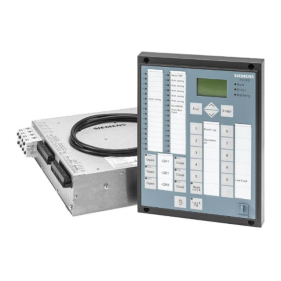
SIPROTEC Compact
Feeder Protection and
Recloser Controller 7SC80
V4.41
Manual
E50417-G1140-C486-A8
Preface
Open Source Software
Table of Contents
Introduction
Functions
Mounting and Commissioning
Technical Data
Ordering Information and Accessories
Terminal Assignments
Connection Examples
Current Transformer Requirements
Default Settings and Protocol-dependent
Functions
Functions, Settings, Information
Literature
Glossary
Index
1
2
3
4
A
B
C
D
E
F
Advertisement
Table of Contents

Related Manuals for Siemens 7SC80


Summary of Contents for Siemens 7SC80
- Page 1 Preface Open Source Software Table of Contents SIPROTEC Compact Introduction Feeder Protection and Functions Recloser Controller 7SC80 Mounting and Commissioning V4.41 Technical Data Ordering Information and Accessories Manual Terminal Assignments Connection Examples Current Transformer Requirements Default Settings and Protocol-dependent Functions...
- Page 2 SIPROTEC, SINAUT, SICAM and DIGSI are registered trade- relations; nor does it change these. All obligations of marks of Siemens AG. Any unauthorized use is illegal. All Siemens AG are stated in the relevant contractual agree- other designations in this document can be trademarks ments.
-
Page 3: Preface
Preface Purpose of this Manual This manual describes the functions, operation, installation, and commissioning of devices 7SC80. In partic- ular, one will find: • Information regarding the configuration of the scope of the device and a description of the device func- tions and settings →... - Page 4 CAUTION indicates that minor personal injury or property damage may result if proper precautions are not taken. This particularly applies to damage to or within the device itself and consequential damage thereof. ² SIPROTEC Compact, 7SC80, Manual E50417-G1140-C486-A8, Edition 07.2017...
- Page 5 Deviations may be permitted in drawings and tables when the type of designator can be obviously derived from the illustration. The following symbols are used in drawings: SIPROTEC Compact, 7SC80, Manual E50417-G1140-C486-A8, Edition 07.2017...
- Page 6 (name) Timer (dropout delay T, example non-adjustable) Dynamic triggered pulse timer T (monoflop) Static memory (SR flipflop) with setting input (S), resetting input (R), output (Q) and inverted output (Q), setting input dominant SIPROTEC Compact, 7SC80, Manual E50417-G1140-C486-A8, Edition 07.2017...
- Page 7 Preface Static memory (RS-flipflop) with setting input (S), resetting input (R), output (Q) and inverted output (Q), resetting input dominant SIPROTEC Compact, 7SC80, Manual E50417-G1140-C486-A8, Edition 07.2017...
- Page 8 SIPROTEC Compact, 7SC80, Manual E50417-G1140-C486-A8, Edition 07.2017...
-
Page 9: Open Source Software
License Conditions provide for it you can order the source code of the Open Source Software from your Siemens sales contact - against payment of the shipping and handling charges - for a period of at least 3 years since purchase of the Product. We are liable for the Product including the Open Source Software contained in it pursuant to the license conditions applicable to the Product. - Page 10 SIPROTEC Compact, 7SC80, Manual E50417-G1140-C486-A8, Edition 07.2017...
-
Page 11: Table Of Contents
Description......................65 2.1.6.2 Setting Notes......................65 2.1.6.3 Settings......................... 68 2.1.6.4 Information List..................... 69 2.1.7 EN100-Module......................69 2.1.7.1 Description......................69 2.1.7.2 Information List..................... 70 Overcurrent Protection 50, 51, 50N, 51N................71 2.2.1 General ........................71 SIPROTEC Compact, 7SC80, Manual E50417-G1140-C486-A8, Edition 07.2017... - Page 12 Setting Notes......................170 2.5.5 Settings........................175 2.5.6 Information List......................186 Voltage Protection 27, 59....................187 2.6.1 Measurement Principle....................187 2.6.2 Overvoltage Protection 59..................189 2.6.3 Undervoltage Protection 27..................189 2.6.4 Displacement Voltage Protection................192 2.6.5 Setting Notes......................194 SIPROTEC Compact, 7SC80, Manual E50417-G1140-C486-A8, Edition 07.2017...
- Page 13 2.12.2.4 Information List....................246 2.12.3 Malfunction Responses of the Monitoring Functions..........246 2.12.3.1 Description......................246 2.13 Ground Fault Protection 64, 67N(s), 50N(s), 51N(s)............248 2.13.1 Ground Fault Detection for cos-φ–/sin-φ Measurement (Standard Method)....248 SIPROTEC Compact, 7SC80, Manual E50417-G1140-C486-A8, Edition 07.2017...
- Page 14 Information List......................335 2.20 Synchrocheck......................... 337 2.20.1 General........................337 2.20.2 Functional Sequence....................338 2.20.3 De-energized Switching..................... 340 2.20.4 Direct Command / Blocking..................340 2.20.5 Interaction with Control, Automatic Reclosing and External Control......341 2.20.6 Setting Notes......................342 SIPROTEC Compact, 7SC80, Manual E50417-G1140-C486-A8, Edition 07.2017...
- Page 15 Information List....................376 2.26.5 Min/Max Measurement Setup..................377 2.26.5.1 Description......................377 2.26.5.2 Setting Notes....................... 377 2.26.5.3 Settings....................... 377 2.26.5.4 Information List....................377 2.26.6 Set Points for Statistic....................379 2.26.6.1 Description......................379 2.26.6.2 Setting Notes....................... 380 SIPROTEC Compact, 7SC80, Manual E50417-G1140-C486-A8, Edition 07.2017...
- Page 16 2.30.4 Voltage-Transformer Supervision of Side 2..............442 2.30.4.1 Description......................442 2.30.4.2 Setting Notes....................... 445 2.30.4.3 Settings....................... 446 2.30.4.4 Information List....................446 Mounting and Commissioning......................... 449 Mounting and Connections..................... 450 3.1.1 Configuration Information..................450 SIPROTEC Compact, 7SC80, Manual E50417-G1140-C486-A8, Edition 07.2017...
- Page 17 Service Conditions..................... 507 4.1.9 Constructive Design....................507 4.1.10 UL certification conditions..................508 Definite-Time Overcurrent Protection 50, 50N..............509 Inverse-Time Overcurrent Protection................511 Directional Overcurrent Protection 67, 67N..............527 Inrush Restraint.......................529 Dynamic Cold Load Pickup....................530 SIPROTEC Compact, 7SC80, Manual E50417-G1140-C486-A8, Edition 07.2017...
- Page 18 Ordering Information 7SC802 ..................584 Ordering Information 7SC803 ..................587 Accessories........................590 Terminal Assignments..........................591 7SC80 — Housing for cabinet flush mounting and cabinet surface mounting ....592 Connection Examples..........................599 Connection Examples for Current and Voltage Transformers..........600 Current Transformer Requirements......................605 Accuracy limiting factors....................
- Page 19 Table of Contents Protocol-dependent Functions..................616 Functions, Settings, Information......................617 Functional Scope......................618 Settings.......................... 621 Information List......................694 Group Alarms........................759 Measured Values......................761 Literature..............................767 Glossary..............................769 Index.................................779 SIPROTEC Compact, 7SC80, Manual E50417-G1140-C486-A8, Edition 07.2017...
- Page 20 SIPROTEC Compact, 7SC80, Manual E50417-G1140-C486-A8, Edition 07.2017...
-
Page 21: Introduction
Introduction This chapter introduces the SIPROTEC Feeder Protection and Recloser Controller 7SC80 and gives an overview of the device's application, properties and functions. Overall Operation Application Scope Characteristics SIPROTEC Compact, 7SC80, Manual E50417-G1140-C486-A8, Edition 07.2017... -
Page 22: Overall Operation
Introduction 1.1 Overall Operation Overall Operation This chapter introduces the SIPROTEC Feeder Protection and Recloser Controller 7SC80 and gives an overview of the device's application, properties and functions. Analog Inputs The measuring inputs (MI) convert the currents and voltages coming from the transformers and adapt them to the level appropriate for the internal processing of the device. - Page 23 1.1 Overall Operation [7sc80-hw-struktur-20110520, 1, en_US] Figure 1-1 Hardware structure Feeder Protection and Recloser Controller 7SC80 Microcomputer System Apart from processing the measured values, the microcomputer system (μC) also executes the actual protec- tion and control functions. They especially include: •...
- Page 24 The HMI of the device is used to connect the operator panel. The operator panel can be permanently attached to the 7SC80 or it can be detached. The operator panel contains 32 LEDs for displaying operating states or indications and a 6-line field for displaying operational indications and measured values or on the Web Monitor a graphical field for displaying the control display.
-
Page 25: Application Scope
1.2 Application Scope Application Scope The Feeder Protection and Recloser Controller 7SC80 can be used to protect, control, and monitor the line protection in networks with grounded, low-resistance grounded, isolated, or compensated neutral. It is suit- able for radial networks supplied from a single source, open or closed looped networks, and for lines with sources at both ends. - Page 26 Alternatively, additional connection options are available with serial DNP3.0 RS485 protocols. If an EN100 module is available, you can use the protocols DNP3 TCP, IEC61850, IEC 60870-5-104, or PROFINET. Further- more, connecting a SICAM I/O unit is possible via IEC61850 GOOSE. SIPROTEC Compact, 7SC80, Manual E50417-G1140-C486-A8, Edition 07.2017...
-
Page 27: Characteristics
Their pickup values and time delays can be set independently of these elements. • For inverse time overcurrent protection, it is possible to select from various characteristics of different standards or define user-specific characteristics SIPROTEC Compact, 7SC80, Manual E50417-G1140-C486-A8, Edition 07.2017... - Page 28 • Monitoring of falling below (f<) and/or exceeding (f>) with 4 frequency limits and time delays that are independently adjustable • Insensitive to harmonics and abrupt phase angle changes • Adjustable undervoltage threshold. SIPROTEC Compact, 7SC80, Manual E50417-G1140-C486-A8, Edition 07.2017...
- Page 29 Sectionalizer • Have no capacity to break the fault current • Isolate the fault current sections of a distribution circuit only when an upstream breaker or recloser has interrupted the fault current. SIPROTEC Compact, 7SC80, Manual E50417-G1140-C486-A8, Edition 07.2017...
- Page 30 Several independent subfunctions have been implemented (ΣΙ-procedure, ΣΙ -procedure, 2P-procedure, and Ι t-procedure) • Acquisition and conditioning of measured values for all subfunctions operates in a phase-selective way using one procedure-specific threshold per subfunction. SIPROTEC Compact, 7SC80, Manual E50417-G1140-C486-A8, Edition 07.2017...
- Page 31 (service interlocking). Device Operation • Device operation via the Web Monitor • Operation via operation panel. The operation panel can also be mounted detached from the device. SIPROTEC Compact, 7SC80, Manual E50417-G1140-C486-A8, Edition 07.2017...
- Page 32 SIPROTEC Compact, 7SC80, Manual E50417-G1140-C486-A8, Edition 07.2017...
-
Page 33: Functions
Functions This chapter describes the numerous functions available on the SIPROTEC 4 device 7SC80. It shows the setting possibilities for each function in maximum configuration. Information with regard to the determination of setting values as well as formulas, if required, are also provided. -
Page 34: General
The available protection functions and additional functions can be configured as Enabled or Disabled. For some functions, there is a choice between several alternatives possible, as described below. Functions configured as Disabled are not processed in the 7SC80, there are no indications and the associ- ated setting parameters (functions, limiting values) are not available. - Page 35 At address 368 AssignMeasInput you can use the input Vx also as LoPo/LPS input. With the setting Ia, Ib, Ic, Vx, any voltage can be connected to the Vx voltage input. SIPROTEC Compact, 7SC80, Manual E50417-G1140-C486-A8, Edition 07.2017...
-
Page 36: Settings
With the setting Ia, INs, Ic, Vx, however, the measuring input Ib is used as sensitive current input In sensitive and the current Ib is calculated. It is thus possible to detect any voltage via the voltage input Vx also in this connection variant. Siemens recommends supplying the Ι input up to 2.5 Ι... - Page 37 25 Function 1 Disabled Disabled 25 Function group 1 SYNCHROCHECK 50BF Disabled Disabled 50BF Breaker Failure Protection Enabled enabled w/ 3I0> Enabled w/o I> 79 Auto Recl. Disabled Disabled 79 Auto-Reclose Function Enabled SIPROTEC Compact, 7SC80, Manual E50417-G1140-C486-A8, Edition 07.2017...
- Page 38 Triple Single Mode Enabled Capacitor Test Disabled Disabled Recloser capacitor Test Enabled Sectionalizer Disabled Disabled Sectionalizer Function With prot. Without prot. VT Con Type S2 CONVENTIONAL CONVENTIONAL Voltage connection type Side2 LoPo/LPS Cap. Volt.Meas. SIPROTEC Compact, 7SC80, Manual E50417-G1140-C486-A8, Edition 07.2017...
-
Page 39: Device, General Settings
These pieces of information are not output if one or more protection functions have picked up during a fault, but the 7SC80 device has not tripped, because the fault was cleared by a different device (on a different line, for example). These pieces of information are then limited to faults on the line to be protected. - Page 40 Firmware Update The 7SC80 provides the option to update the device firmware via Ethernet. To do so, you need the program remote_firmware_update.exe which is available on the SIPROTEC homepage. The function can be enabled or disabled.
-
Page 41: Setting Notes
EN100+ module are optimized for the fastest possible transmission of multiple concurrent status changes of binary values. This might require a special version of the EN100 firm- ware, which is available in the 7SC80 Sharepoint/Download area. This results in the following restrictions: •... - Page 42 For the battery test under load, it is necessary first to disconnect the external battery charger from the battery and then to connect an external, defined load impedance. The 7SC80 provides two binary signals for this purpose. With the signal 2539 Execut.
- Page 43 After a waiting period of 30 minutes, the battery is again monitored cyclically every 600 ms in trickle charging mode. Upon triggering of a protection function of the 7SC80, any running battery test is aborted, the test impedance is disconnected from the battery (2596 Test load act.
- Page 44 Switching operations are only allowed if none of the three indications is active. As soon as the status of at least one of the 3 indications changes to active, however, any switching state changes of the discon- nector/circuit breaker are suppressed. SIPROTEC Compact, 7SC80, Manual E50417-G1140-C486-A8, Edition 07.2017...
- Page 45 The following figure shows a sample circuit. With each keystroke, the inverted actual state of the service interlocking is transferred to the memory. Alternatively, you can use 2 binary inputs as separate ON/OFF buttons. SIPROTEC Compact, 7SC80, Manual E50417-G1140-C486-A8, Edition 07.2017...
-
Page 46: Settings
Fast GOOSE transmission EvLog Fill Lev1 10 .. 100 % 70 % Threshold Fill level 1 Event Log EvLog Fill Lev2 10 .. 100 % 90 % Threshold Fill level 2 Event Log SIPROTEC Compact, 7SC80, Manual E50417-G1140-C486-A8, Edition 07.2017... -
Page 47: Information List
Alarm: NO calibration data available Error neutralCT Error: Neutral CT different from MLFB Pow.Sys.Flt. Power System fault Fault Event Fault Event sens Gnd flt sensitive Ground fault Warn Mem. Data Warn: Limit of Memory Data exceeded SIPROTEC Compact, 7SC80, Manual E50417-G1140-C486-A8, Edition 07.2017... -
Page 48: Power System Data 1
(where applicable), etc. There are also certain parameters that are common to all functions, i.e. not associated with a specific protec- tion, control or monitoring function. The following section discusses this data. SIPROTEC Compact, 7SC80, Manual E50417-G1140-C486-A8, Edition 07.2017... -
Page 49: Setting Notes
Voltage Connection (Power System) Address 213 specifies how the voltage transformers are connected. VT Connect. 3ph = Van, Vbn, Vcn means that the three phase voltages are wye connected, i.e. the three phase-to-ground voltages are measured. SIPROTEC Compact, 7SC80, Manual E50417-G1140-C486-A8, Edition 07.2017... - Page 50 Capacitive voltage measurement always measures the phase-to-ground voltages from the protection device. The following figure shows this type of connection. [7sc80-kapazitiver-u-anschluss-240113, 1, en_US] Figure 2-5 Connection Principle for a Capacitive Voltage Measurement SIPROTEC Compact, 7SC80, Manual E50417-G1140-C486-A8, Edition 07.2017...
- Page 51 As an additional parameter, the value C , which is the sum of line capacitance S,LX and stray capacitance, is varied in the range from 2000 pF to 10 000 pF in increments of 500 pF. SIPROTEC Compact, 7SC80, Manual E50417-G1140-C486-A8, Edition 07.2017...
- Page 52 “Device Failure” and 10036 Capac.Par.Fail. after startup. NOTE The bushing capacitances used only have to be available to the connected 7SC80. It is therefore not permitted to connect, for example, a capacitive voltage measuring device to the same bushing capaci- tances! Internal Normalization of the Measured Voltages The capacitance values for the three voltage inputs will usually not be absolutely identical.
- Page 53 (phase-to-phase) of the connected voltage transformers. At addresses 333 Vnom prim Vx and 325 Vnom sec Vx, you can enter the primary and secondary rated voltage for the 4th voltage input Vx. SIPROTEC Compact, 7SC80, Manual E50417-G1140-C486-A8, Edition 07.2017...
- Page 54 When using a 300 A/225 mV current sensor, currents from approx. 5 A can thus be measured; with different transformation ratios, correspondingly lower currents. The allowed range of secondary nominal phase current for protection in 7SC80 firmware is from 15 mV to 25 V. If it is out of range, indication 2184 CT LPS mismatch occurs and the function of the device will be blocked to avoid unexpected operation.
- Page 55 At address 349 Vx AMPL COR, enter the correction factor for the 4th voltage transformer Vx. This allows system-related deviations of voltage measurement to be compensated for. SIPROTEC Compact, 7SC80, Manual E50417-G1140-C486-A8, Edition 07.2017...
- Page 56 In a 3-phase connection, overvoltage protection optionally uses the following quantities: • Fundamental harmonic of the largest of the phase-to-phase voltages (Vphph) • Fundamental harmonic of the largest of the phase-to-ground voltages (Vph-n) • Positive sequence voltage (V1) SIPROTEC Compact, 7SC80, Manual E50417-G1140-C486-A8, Edition 07.2017...
-
Page 57: Settings
0.04 .. 1.00 A 0.04 A Closed Breaker Min. Current Threshold 0.20 .. 5.00 A 0.20 A VT Connect. 3ph Van, Vbn, Vcn Van, Vbn, Vcn VT Connection, three- phase Vab, Vbc, VGnd Vab, Vbc SIPROTEC Compact, 7SC80, Manual E50417-G1140-C486-A8, Edition 07.2017... - Page 58 250 .. 10000 pF 2200 pF Voltage transducer 2B: Capacity C2 Volt.tran.2C:C1 1.0 .. 100.0 pF 10.0 pF Voltage transducer 2C: Capacity C1 Volt.tran.2C:C2 250 .. 10000 pF 2200 pF Voltage transducer 2C: Capacity C2 SIPROTEC Compact, 7SC80, Manual E50417-G1140-C486-A8, Edition 07.2017...
- Page 59 Rated sec. volt. f. earth curr. LoPo/LPS 337A CT Ph. Connect. A B C A B C CT Phase terminal connec- tion B C A C A B A C B B A C C B A SIPROTEC Compact, 7SC80, Manual E50417-G1140-C486-A8, Edition 07.2017...
- Page 60 2C 365A VT Ph. Con. S2 A B C A B C VT Phase terminal connec- tion Side2 B C A C A B A C B B A C C B A SIPROTEC Compact, 7SC80, Manual E50417-G1140-C486-A8, Edition 07.2017...
-
Page 61: Information List
Malparameteriz. Volt.-divider Capacities 2.1.4 Oscillographic Fault Records Feeder Protection and Recloser Controller 7SC80 features a fault memory. The instantaneous values of the measurands and u (voltages depending on connection) are sampled at intervals of 1.0 ms (at 50 Hz) and stored in a revolving buffer (20 samples per cycle). -
Page 62: Description
Storage is then triggered dynamically. The length of the fault recording is set in address 406 BinIn CAPT.TIME (but not longer than MAX. LENGTH, address 403). Pre-fault and post-fault times will add to this. SIPROTEC Compact, 7SC80, Manual E50417-G1140-C486-A8, Edition 07.2017... -
Page 63: Settings
A setting group includes the parameter values for all functions that have been selected as Enabled during configuration (see Section 2.1.1.2 Setting Notes). In 7SC80 devices, 16 independent setting groups (A to P) are supported. Whereas the setting values may vary, the selected functions of each setting group remain the same. -
Page 64: Settings
Setting Group P is active >Set Group Bit0 >Setting Group Select Bit 0 >Set Group Bit1 >Setting Group Select Bit 1 >Set Group Bit2 >Setting Group Select Bit 2 >Set Group Bit3 >Setting Group Select Bit 3 SIPROTEC Compact, 7SC80, Manual E50417-G1140-C486-A8, Edition 07.2017... -
Page 65: Power System Data 2
/s = 1.26 Ω/km (2.03 Ω/mile) Zero sequence reactance /s = 0.24 Ω/km (0.39 Ω/mile) Positive sequence resistance /s = 0.34 Ω/km (0.55 Ω/mile) Positive sequence reactance For ground impedance ratios, the following results: SIPROTEC Compact, 7SC80, Manual E50417-G1140-C486-A8, Edition 07.2017... - Page 66 Line Angle (only for Fault Location) The setting of the line angle is only important for the utilization of the line fault location function. The line angle can be derived from the line constants. The following applies: SIPROTEC Compact, 7SC80, Manual E50417-G1140-C486-A8, Edition 07.2017...
- Page 67 1108 P,Q sign to reversed. If the setting is not reversed (default), the positive direction for the power etc. corresponds to the "forward" direction for the protection functions. Section 4 Technical Data provides a detailed list of the values in question. SIPROTEC Compact, 7SC80, Manual E50417-G1140-C486-A8, Edition 07.2017...
-
Page 68: Settings
S2: Line length in kilometer 6021 S3: RE/RL -0.33 .. 7.00 1.00 S3: Zero seq. compen- sating factor RE/RL 6022 S3: XE/XL -0.33 .. 7.00 1.00 S3: Zero seq. compen- sating factor XE/XL SIPROTEC Compact, 7SC80, Manual E50417-G1140-C486-A8, Edition 07.2017... -
Page 69: Information List
2.1.7.1 Description The EN100-Module enables integration of the 7SC80 in 100-Mbit communication networks in control and automation systems with the protocols according to IEC 61850 standard. This standard permits uniform communication of the devices without gateways and protocol converters. Even when installed in heteroge- neous environments, SIPROTEC 4 relays therefore provide for open and interoperable operation. -
Page 70: Information List
The GOOSE function can be disabled in a device parameter. For more information, please refer to Section 2.1.2.2 Setting Notes. You can use an optical or electrical EN100-Module with 2 ports for IEC 61850 and/or DNP 3.0 TCP and/or PROFINET and/or IEC 60870-5-104 in the 7SC80 Feeder Protection and Recloser Controller. 2.1.7.2 Information List Information... -
Page 71: Overcurrent Protection 50, 51, 50N, 51N
2.2 Overcurrent Protection 50, 51, 50N, 51N Overcurrent Protection 50, 51, 50N, 51N The overcurrent protection is the main protection function of the 7SC80 relay. Each phase current and ground current is provided with three definite time and several inverse time elements. All elements are independent from each other and can be combined as desired. -
Page 72: Definite Time Overcurrent Elements 50-1, 50N-1
The pickup values of each 50-1 element for phase currents and 50N-1 element for the ground current and the element-specific time delays can be set individually. The following figures show the logic diagrams for the current elements 50-1 and 50N-1. SIPROTEC Compact, 7SC80, Manual E50417-G1140-C486-A8, Edition 07.2017... - Page 73 The dropout delay only operates when no inrush was detected. An incoming inrush resets an already running dropout time delay. [7sj6x_rueckfallverzoegerung_i_gr_ph_260803_he, 1, en_US] Figure 2-8 Logic diagram of the dropout delay for 50-1 SIPROTEC Compact, 7SC80, Manual E50417-G1140-C486-A8, Edition 07.2017...
-
Page 74: Inverse Time Overcurrent Elements 51, 51N
The inverse time overcurrent elements depend on the order variant. They always operate with an inverse time characteristic according to IEC or ANSI standards, a user-defined characteristic, or a recloser characteristic. The characteristic curves and associated formulas are shown in the Technical Data. SIPROTEC Compact, 7SC80, Manual E50417-G1140-C486-A8, Edition 07.2017... - Page 75 Pickup values of elements 51 (phase currents) and 51N (ground current) and the relevant time multiplicators may be set individually. The following two figures show the logic diagrams for the inverse time overcurrent protection. SIPROTEC Compact, 7SC80, Manual E50417-G1140-C486-A8, Edition 07.2017...
- Page 76 If parameter 1213 MANUAL CLOSE is set to 51 instant. and manual close detection is used, a pickup causes instantaneous tripping even if the element is blocked via a binary input. The same applies to 79 AR 51 inst. SIPROTEC Compact, 7SC80, Manual E50417-G1140-C486-A8, Edition 07.2017...
- Page 77 This process corresponds to the reset of a Ferraris disk (explaining its denomination “disk emulation”). In case several faults occur in succession, the "history" is taken into consideration due to the inertia of the SIPROTEC Compact, 7SC80, Manual E50417-G1140-C486-A8, Edition 07.2017...
-
Page 78: Inverse Time Overcurrent Elements 51-1, 51-2, 51-3, 51-4 And 51N-1, 51N-2, 51N-3, 51N-4
Pickup values of elements and the relevant time multiplicators may be set individually The following two figures show the logic diagrams for the 51-1 and 51N-1 inverse time overcurrent protection respectively. SIPROTEC Compact, 7SC80, Manual E50417-G1140-C486-A8, Edition 07.2017... - Page 79 The same applies to 79 AR 51-1 inst., 79 AR 51-2 inst., 79 AR 51-3 inst., 79 AR 51-4 inst.. SIPROTEC Compact, 7SC80, Manual E50417-G1140-C486-A8, Edition 07.2017...
- Page 80 Ferraris disk and the time response is adapted. Reset begins as soon as 90 % of the setting value is undershot, in accordance to the dropout curve of the selected characteristic. In the range between the dropout value (95 SIPROTEC Compact, 7SC80, Manual E50417-G1140-C486-A8, Edition 07.2017...
-
Page 81: Inverse Time Overcurrent Protection 51V (Voltage-Controlled/Voltage-Restraint)
Ι/ 51 PICKUP ratio is increased and the tripping time is reduced. Compared with the standard curves repre- sented in Section “Technical Data”, the tripping curve shifts to the left side as the voltage decreases. SIPROTEC Compact, 7SC80, Manual E50417-G1140-C486-A8, Edition 07.2017... - Page 82 The following two figures show the logic diagrams for the inverse time overcurrent protection with under- voltage consideration. SIPROTEC Compact, 7SC80, Manual E50417-G1140-C486-A8, Edition 07.2017...
- Page 83 Functions 2.2 Overcurrent Protection 50, 51, 50N, 51N [7sjx_logic_51-phase-schleife-aktiv, 1, en_US] Figure 2-16 Logic diagram of the voltage-controlled inverse time overcurrent protection SIPROTEC Compact, 7SC80, Manual E50417-G1140-C486-A8, Edition 07.2017...
-
Page 84: Special Variant Function 50-1, 50N-1 For Service Interlocking
6090 50 HLT BLOCKED or 6094 50N HLT BLOCKED . When service interlocking is activated, the blocking of this element is reset. The following figure applies analogously also to the ground current. SIPROTEC Compact, 7SC80, Manual E50417-G1140-C486-A8, Edition 07.2017... -
Page 85: Dynamic Cold Load Pickup Function
2.2.9 Inrush Restraint The 7SC80 Feeder Protection and Recloser Controller features an inrush current detection which you can acti- vate separately for each element of the overcurrent protection. The function is described in Section 2.12.1 Measurement Supervision. - Page 86 50-1 B PU Figure 2-7 1810 50-1 picked up 50-1 C PU Figure 2-7 50N-1 PU 1834 50N-1 picked up 51 A PU 51 B PU 1820 51 picked up 51 C PU SIPROTEC Compact, 7SC80, Manual E50417-G1140-C486-A8, Edition 07.2017...
-
Page 87: Two-Phase Overcurrent Protection (Only Non-Directional)
The current amplitude is derived from the sampled values in accordance with the definition equation of the true RMS value. This measurement method should be selected when higher harmonics are to be considered by the function (e.g. in capacitor banks). SIPROTEC Compact, 7SC80, Manual E50417-G1140-C486-A8, Edition 07.2017... - Page 88 = 84 A (High Voltage Side) = 462 A (Low Voltage Ι Ι NomT, 110 NomT, 20 Side) Current Transformer (High Voltage Side) 100 A/1 A Current Transformer (Low Voltage Side) 500 A/1 A SIPROTEC Compact, 7SC80, Manual E50417-G1140-C486-A8, Edition 07.2017...
- Page 89 If the 50N-1 element is not required at all, the pickup threshold 50N-1 PICKUP should be set to ∞. This setting prevents tripping and the generation of a pickup message. SIPROTEC Compact, 7SC80, Manual E50417-G1140-C486-A8, Edition 07.2017...
- Page 90 This means that a pickup will only occur if a current of about 1.1 times the setting value is present. If Disk Emulation were selected at address 1235 SIPROTEC Compact, 7SC80, Manual E50417-G1140-C486-A8, Edition 07.2017...
- Page 91 This means that a pickup will only occur if a current of about 1.1 times the setting value is present. If Disk Emulations were selected at address 1335 SIPROTEC Compact, 7SC80, Manual E50417-G1140-C486-A8, Edition 07.2017...
- Page 92 5.50 7.00 10.00 17.00 1.19 1.69 2.75 4.25 5.75 7.25 11.00 18.00 1.25 1.75 3.00 4.50 6.00 7.50 12.00 19.00 1.31 1.81 3.25 4.75 6.25 7.75 13.00 20.00 1.38 1.88 14.00 1.44 1.94 SIPROTEC Compact, 7SC80, Manual E50417-G1140-C486-A8, Edition 07.2017...
- Page 93 The respective upper limits of the ranges of value are indicated by dotted lines in the right-hand and upper area of the system of coordinates. If the position of a data point lies outside these limits, the associated value is set to infinity. SIPROTEC Compact, 7SC80, Manual E50417-G1140-C486-A8, Edition 07.2017...
- Page 94 Parameter 1325 51N Time adder. Inrush Restraint When using the protection device at transformers with large inrush currents, the inrush current detection can be activated in the 7SC80. The general setting notes for the inrush current detection are described in Section 2.12.1.8 Setting Notes.
- Page 95 Manual close feature External Control Command If the manual closing signal is not sent from the 7SC80 Feeder Protection and Recloser Controller, but directly from a control acknowledgment switch, this signal must be forwarded to a binary input of 7SC80 and routed accordingly ( >Manual Close ) so that the element selected for MANUAL CLOSE can take effect.
-
Page 96: Settings
79 active 1217 50-3 PICKUP 1.00 .. 30.00 A; ∞ ∞ A 50-3 Pickup 5.00 .. 150.00 A; ∞ ∞ A 1218 50-3 DELAY 0.00 .. 60.00 sec; ∞ 0.00 sec 50-3 Time Delay SIPROTEC Compact, 7SC80, Manual E50417-G1140-C486-A8, Edition 07.2017... - Page 97 0.01 .. 20.00 sec; ∞ 0.50 sec 51-1 Time Dial 1235 51-1 Drop-out Instantaneous Disk Emulation Drop-out characteristic Disk Emulation 1236 51-1 IEC Curve Normal Inverse 51-1 IEC Curve Normal Inverse Very Inverse Extremely Inv. Long Inverse SIPROTEC Compact, 7SC80, Manual E50417-G1140-C486-A8, Edition 07.2017...
- Page 98 1267 51-4 PICKUP 0.02 .. 4.00 A; ∞ 1.00 A 51-4 Pickup 0.10 .. 20.00 A; ∞ 5.00 A 1268 51-4 TIME DIAL 0.01 .. 20.00 sec; ∞ 0.50 sec 51-4 Time Dial SIPROTEC Compact, 7SC80, Manual E50417-G1140-C486-A8, Edition 07.2017...
- Page 99 Curve E (132) Curve K (162) Curve N (104) Curve R (105) Curve W (138) Curve 2 (135) Curve 3 (140) Curve 8 (113) Curve 8* (111) Curve 9 (131) Curve 11 (141) SIPROTEC Compact, 7SC80, Manual E50417-G1140-C486-A8, Edition 07.2017...
- Page 100 Curve E (132) Curve K (162) Curve N (104) Curve R (105) Curve W (138) Curve 2 (135) Curve 3 (140) Curve 8 (113) Curve 8* (111) Curve 9 (131) Curve 11 (141) SIPROTEC Compact, 7SC80, Manual E50417-G1140-C486-A8, Edition 07.2017...
- Page 101 0.50 .. 15.00 ; ∞ 5.00 51N Time Dial 1310 51N Drop-out Instantaneous Disk Emulation Drop-Out Characteristic Disk Emulation 1311 51N IEC CURVE Normal Inverse Normal Inverse IEC Curve Very Inverse Extremely Inv. Long Inverse SIPROTEC Compact, 7SC80, Manual E50417-G1140-C486-A8, Edition 07.2017...
- Page 102 50N-1 measurem. Fundamental Fundamental 50N-1 measurement of True RMS 1322A 51N measurem. Fundamental Fundamental 51N measurement of True RMS 1325A 51N Time adder 0.00 .. 30.00 sec 0.00 sec Constant time adder 51N SIPROTEC Compact, 7SC80, Manual E50417-G1140-C486-A8, Edition 07.2017...
- Page 103 51N-2 IEC Curve Normal Inverse Very Inverse Extremely Inv. Long Inverse 1343 51N-2 T adder 0.00 .. 30.00 sec 0.00 sec Constant time adder 51N-2 1344A 51N-3 measure. Fundamental Fundamental 51N-3 measurement of True RMS SIPROTEC Compact, 7SC80, Manual E50417-G1140-C486-A8, Edition 07.2017...
- Page 104 Curve E (132) Curve K (162) Curve N (104) Curve R (105) Curve W (138) Curve 2 (135) Curve 3 (140) Curve 8 (113) Curve 8* (111) Curve 9 (131) Curve 11 (141) SIPROTEC Compact, 7SC80, Manual E50417-G1140-C486-A8, Edition 07.2017...
- Page 105 Curve E (132) Curve K (162) Curve N (104) Curve R (105) Curve W (138) Curve 2 (135) Curve 3 (140) Curve 8 (113) Curve 8* (111) Curve 9 (131) Curve 11 (141) SIPROTEC Compact, 7SC80, Manual E50417-G1140-C486-A8, Edition 07.2017...
- Page 106 50-3 with Inrush Restraint 2210 51 w. Inrush 51 with Inrush Restraint 2211 50N-1 w. Inrush 50N-1 with Inrush Restraint 2212 50N-2 w. Inrush 50N-2 with Inrush Restraint 2213 50N-3 w. Inrush 50N-3 with Inrush Restraint SIPROTEC Compact, 7SC80, Manual E50417-G1140-C486-A8, Edition 07.2017...
-
Page 107: Information List
50/51 Phase B picked up 1764 50/51 Ph C PU 50/51 Phase C picked up 1765 50N/51NPickedup 50N/51N picked up 1767 50-3 picked up 50-3 picked up 1768 50N-3 picked up 50N-3 picked up SIPROTEC Compact, 7SC80, Manual E50417-G1140-C486-A8, Edition 07.2017... - Page 108 50N Hotline Tag picked up 6093 50N HLT TRIP 50N Hotline Tag TRIP 6094 50N HLT BLOCKED 50N HLT is BLOCKED 7551 50-1 InRushPU 50-1 InRush picked up 7552 50N-1 InRushPU 50N-1 InRush picked up SIPROTEC Compact, 7SC80, Manual E50417-G1140-C486-A8, Edition 07.2017...
- Page 109 51N-2 InRushPU 51N-2 InRush picked up 31067 >BLOCK 51N-3 >BLOCK 51N-3 31068 51N-3 picked up 51N-3 picked up 31069 51N-3 TRIP 51N-3 TRIP 31070 51N-3 TimeOut 51N-3 Time Out 31071 51N-3 BLOCKED 51N-3 BLOCKED SIPROTEC Compact, 7SC80, Manual E50417-G1140-C486-A8, Edition 07.2017...
- Page 110 51-4 curve multi-selection error 31163 51N-1 Curve Er. 51N-1 curve multi-selection error 31164 51N-2 Curve Er. 51N-2 curve multi-selection error 31165 51N-3 Curve Er. 51N-3 curve multi-selection error 31166 51N-4 Curve Er. 51N-4 curve multi-selection error SIPROTEC Compact, 7SC80, Manual E50417-G1140-C486-A8, Edition 07.2017...
-
Page 111: Directional Overcurrent Protection 67, 67N
Applications • The directional overcurrent protection allows the 7SC80 Feeder Protection and Recloser Controller to be used also in power systems where protection coordination depends on knowing both the magnitude of the fault current and the direction of power flow to the fault location. -
Page 112: Directional Definite Time High-Current Elements 67-2, 67-3, 67N-2 And 67N-3
The trip command delay times 50-2 DELAY, 67-3 DELAY or 50N-2 DELAY, 67N-3 DELAY continue in the meantime. After the expiry of the dropout delay time, the SIPROTEC Compact, 7SC80, Manual E50417-G1140-C486-A8, Edition 07.2017... -
Page 113: Definite Time, Directional Time Overcurrent Elements 67-1, 67N-1
Each of these elements can be directional or non-directional. These elements can be blocked by the automatic reclosing function (AR). The following figure shows by way of an example the logic diagram for the directional overcurrent element 67-1. SIPROTEC Compact, 7SC80, Manual E50417-G1140-C486-A8, Edition 07.2017... - Page 114 The same applies to 79 AR 67-1 instantaneous. The dropout delay does only function if no inrush was detected. An approaching inrush resets an already running dropout time delay. SIPROTEC Compact, 7SC80, Manual E50417-G1140-C486-A8, Edition 07.2017...
-
Page 115: Inverse Time, Directional Time Overcurrent Elements 67-Toc, 67N-Toc
Disk emulation offers advantages when the overcurrent relay elements must be coordinated with conven- tional electromechanical overcurrent relays located towards the source. For recloser characteristics, an element drops out immediately after the value has fallen below a threshold. SIPROTEC Compact, 7SC80, Manual E50417-G1140-C486-A8, Edition 07.2017... - Page 116 95% of the pickup setting. When a new pickup occurs, the timer starts at zero again. The following figure shows by way of an example the logic diagram for the 67-TOC relay element of the direc- tional inverse time overcurrent protection of the phase currents. SIPROTEC Compact, 7SC80, Manual E50417-G1140-C486-A8, Edition 07.2017...
-
Page 117: Inverse Time, Directional Time Overcurrent Elements 67-Toc-1, 67-Toc-2, 67- Toc-3, 67-Toc-4 And 67N-Toc-1, 67N-Toc-2, 67N-Toc-3, 67N-Toc-4
TOC-3, 67-TOC-4 and 67N-TOC-1, 67N-TOC-2, 67N-TOC-3, 67N-TOC-4 There are 4 inverse elements for Recloser, you can pre-define these 4 inverse elements in overcurrent protec- tion independently without any type restriction, then assign them in each recloser cycle. SIPROTEC Compact, 7SC80, Manual E50417-G1140-C486-A8, Edition 07.2017... - Page 118 For recloser characteristics, an element drops out immediately after the value has fallen below a threshold. The following two figures show the logic diagrams for the 67-TOC-1 and 67N-TOC-1 inverse time overcurrent protection respectively. SIPROTEC Compact, 7SC80, Manual E50417-G1140-C486-A8, Edition 07.2017...
- Page 119 Functions 2.3 Directional Overcurrent Protection 67, 67N [Lo_67-TOC-1, 1, en_US] Figure 2-28 Logic diagram of the directional overcurrent protection; example: inverse time overcurrent element 67-TOC- 1, phases SIPROTEC Compact, 7SC80, Manual E50417-G1140-C486-A8, Edition 07.2017...
- Page 120 The minimum operating time defines the minimum interval for tripping the inverse element. When an inverse element picks up, an individual time 67-TOC-1MinO.T, 67-TOC-2MinO.T, 67-TOC-3MinO.T, 67- TOC-4MinO.T, 67N-TOC-1MinO.T, 67N-TOC-2MinO.T, 67N-TOC-3MinO.T, 67N-TOC-4MinO.T starts. The inverse element can only trip after the minimum operating time elapses. SIPROTEC Compact, 7SC80, Manual E50417-G1140-C486-A8, Edition 07.2017...
-
Page 121: Interaction With Voltage Monitoring
Inrush Restraint 2.3.8 The 7SC80 Feeder Protection and Recloser Controller features an inrush current detection which you can acti- vate separately for each element of the directional overcurrent protection. The function is described in Section 2.12.1 Measurement Supervision. - Page 122 — — — — Ι — — — — — — Ι — — — — — — Ι — — — — — — Ι A, N — — — — Ι SIPROTEC Compact, 7SC80, Manual E50417-G1140-C486-A8, Edition 07.2017...
- Page 123 If the vector of the fault current is in this area, the ref,rot device detects forward direction. In the mirrored area, the device detects reverse direction. In the intermediate area, the direction result is undefined. SIPROTEC Compact, 7SC80, Manual E50417-G1140-C486-A8, Edition 07.2017...
- Page 124 The forward area is also a range of ±86° around the rotated reference voltage V . If the vector of the fault ref, rot current -Ι (or Ι ) is in this area, the device detects forward direction. SIPROTEC Compact, 7SC80, Manual E50417-G1140-C486-A8, Edition 07.2017...
-
Page 125: Setting Notes
Measurement of the Fundamental Harmonic (standard method): This measurement method processes the sampled values of the current and filters in numerical order the fundamental harmonic so that the higher harmonics or transient peak currents are rejected. SIPROTEC Compact, 7SC80, Manual E50417-G1140-C486-A8, Edition 07.2017... - Page 126 0° (remote fault) and 30° (close-up fault) depending on the collapse of the faulty voltage. This can be taken into account with a mean value of 15°: Ref. volt. angle of rotation = 90 - φ -15° Phase directional element (phase-to-phase fault). SIPROTEC Compact, 7SC80, Manual E50417-G1140-C486-A8, Edition 07.2017...
- Page 127 Address 1623 67N-2 Direction • Address 1624 67N-1 Direction • Address 1625 67N-TOC Direct. • Address 1640 67N-TOC-1 Dir. • Address 1641 67N-TOC-2 Dir. • Address 1642 67N-TOC-3 Dir. • Address 1643 67N-TOC-4 Dir. SIPROTEC Compact, 7SC80, Manual E50417-G1140-C486-A8, Edition 07.2017...
- Page 128 The selected time is only an additional time delay and does not include the operating time (measuring time, dropout time). The delay can be set to ∞. After pickup the element will then not trip. Pickup, however, will be SIPROTEC Compact, 7SC80, Manual E50417-G1140-C486-A8, Edition 07.2017...
- Page 129 IEC, ANSI, or Recloser indivitually. For each element, you select one of tree parameters. The other two parameters must be set to NO. For example, for the element 67-TOC-1 you can select: SIPROTEC Compact, 7SC80, Manual E50417-G1140-C486-A8, Edition 07.2017...
- Page 130 Notes), the elements 51-1, 51-2, 51-3, 51-4 are available. For each element, you can select the curve type IEC, ANSI, or Recloser indivitually. For each element, you select one of tree parameters. The other two parameters must be set to NO. SIPROTEC Compact, 7SC80, Manual E50417-G1140-C486-A8, Edition 07.2017...
- Page 131 MofPU = 1 bis 1.94 MofPU = 2 bis 4.75 MofPU = 5 bis 7.75 MofPU = 8 bis 20 1.00 1.50 2.00 3.50 5.00 6.50 8.00 15.00 1.06 1.56 2.25 3.75 5.25 6.75 9.00 16.00 SIPROTEC Compact, 7SC80, Manual E50417-G1140-C486-A8, Edition 07.2017...
- Page 132 You can prolong the tripping time by a parameterizable, constant time. The overcurrent element 67-TOC is set using parameter 2225 67-TOC T adder and the overcurrent element 67N-TOC using parameter 2325 67N- TOC T adder. SIPROTEC Compact, 7SC80, Manual E50417-G1140-C486-A8, Edition 07.2017...
- Page 133 External Control Switch If the manual close signal is not from the 7SC80 device, that is, neither sent via the built-in operator interface nor via a serial port but directly from a control acknowledgment switch, this signal must be passed to a 7SC80 binary input, and configured accordingly ( >Manual Close ), so that the element selected for MANUAL...
-
Page 134: Settings
If this is not desired, the setting always is selected so that the 67-2 elements are always active. The integrated automatic reclosing function of 7SC80 also provides the option to determine individually for each overcurrent element whether tripping or blocking is to be carried out instantaneously, unaffected by the AR with time delay (see Section 2.14 Automatic Reclosing System... - Page 135 Fundamental 67-TOC measurement of True RMS 1523 67-2 Direction Forward Forward 67-2 Direction Reverse Non-Directional 1524 67-1 Direction Forward Forward 67-1 Direction Reverse Non-Directional 1525 67-TOC Direct. Forward Forward 67-TOC Direction Reverse Non-Directional SIPROTEC Compact, 7SC80, Manual E50417-G1140-C486-A8, Edition 07.2017...
- Page 136 67-TOC-1 Pickup 0.10 .. 20.00 A; ∞ 5.00 A 1545 67-TOC-1 T DIAL 0.01 .. 20.00 sec; ∞ 0.50 sec 67-TOC-1 Time Dial 1546A 67-TOC-1 MEAS. Fundamental Fundamental 67-TOC-1 measurement of True RMS SIPROTEC Compact, 7SC80, Manual E50417-G1140-C486-A8, Edition 07.2017...
- Page 137 67-TOC-4 T DIAL 0.01 .. 20.00 sec; ∞ 0.50 sec 67-TOC-4 Time Dial 1564A 67-TOC-4 MEAS. Fundamental Fundamental 67-TOC-4 measurement of True RMS 1565 67-TOC-4 Drop. Instantaneous Disk Emulation Drop-Out Characteristic Disk Emulation SIPROTEC Compact, 7SC80, Manual E50417-G1140-C486-A8, Edition 07.2017...
- Page 138 Curve 3 (140) Curve 8 (113) Curve 8* (111) Curve 9 (131) Curve 11 (141) 1570 67-TOC-2 ANSI 67-TOC-2 ANSI Curve Very Inverse Inverse Short Inverse Long Inverse Moderately Inv. Extremely Inv. Definite Inv. SIPROTEC Compact, 7SC80, Manual E50417-G1140-C486-A8, Edition 07.2017...
- Page 139 Curve 3 (140) Curve 8 (113) Curve 8* (111) Curve 9 (131) Curve 11 (141) 1574 67-TOC-4 ANSI 67-TOC-4 ANSI Curve Very Inverse Inverse Short Inverse Long Inverse Moderately Inv. Extremely Inv. Definite Inv. SIPROTEC Compact, 7SC80, Manual E50417-G1140-C486-A8, Edition 07.2017...
- Page 140 0.50 .. 15.00 ; ∞ 5.00 67N-TOC Time Dial 1610 67N-TOC DropOut Instantaneous Disk Emulation Drop-Out Characteristic Disk Emulation 1611 67N-TOC IEC Normal Inverse Normal Inverse IEC Curve Very Inverse Extremely Inv. Long Inverse SIPROTEC Compact, 7SC80, Manual E50417-G1140-C486-A8, Edition 07.2017...
- Page 141 Fundamental 67N-TOC measurement of True RMS 1623 67N-2 Direction Forward Forward 67N-2 Direction Reverse Non-Directional 1624 67N-1 Direction Forward Forward 67N-1 Direction Reverse Non-Directional 1625 67N-TOC Direct. Forward Forward 67N-TOC Direction Reverse Non-Directional SIPROTEC Compact, 7SC80, Manual E50417-G1140-C486-A8, Edition 07.2017...
- Page 142 1.00 A 67N-TOC-1 Pickup 0.25 .. 20.00 A; ∞ 5.00 A 1645 67N-TOC-1 TD 0.01 .. 20.00 sec; ∞ 0.50 sec 67N-TOC-1 Time Dial 1646A 67N-TOC-1 MEAS. Fundamental Fundamental 67N-TOC-1 measurement True RMS SIPROTEC Compact, 7SC80, Manual E50417-G1140-C486-A8, Edition 07.2017...
- Page 143 5.00 A 1663 67N-TOC-4 TD 0.01 .. 20.00 sec; ∞ 0.50 sec 67N-TOC-4 Time Dial 1664A 67N-TOC-4 MEAS. Fundamental Fundamental 67N-TOC-4 measurement True RMS 1665 67N-TOC-4 Drop. Instantaneous Disk Emulation Drop-Out Characteristic Disk Emulation SIPROTEC Compact, 7SC80, Manual E50417-G1140-C486-A8, Edition 07.2017...
- Page 144 Curve 3 (140) Curve 8 (113) Curve 8* (111) Curve 9 (131) Curve 11 (141) 1670 67N-TOC-2 ANSI 67N-TOC-2 ANSI Curve Very Inverse Inverse Short Inverse Long Inverse Moderately Inv. Extremely Inv. Definite Inv. SIPROTEC Compact, 7SC80, Manual E50417-G1140-C486-A8, Edition 07.2017...
- Page 145 Curve 3 (140) Curve 8 (113) Curve 8* (111) Curve 9 (131) Curve 11 (141) 1674 67N-TOC-4 ANSI 67N-TOC-4 ANSI Curve Very Inverse Inverse Short Inverse Long Inverse Moderately Inv. Extremely Inv. Definite Inv. SIPROTEC Compact, 7SC80, Manual E50417-G1140-C486-A8, Edition 07.2017...
- Page 146 Restraint 2231 67-TOC-2 w. In. 67-TOC-2 with Inrush Restraint 2232 67-TOC-3 w. In. 67-TOC-3 with Inrush Restraint 2233 67-TOC-4 w. In. 67-TOC-4 with Inrush Restraint 2234 67N-TOC-1 w. I. 67N-TOC-1 with Inrush Restraint SIPROTEC Compact, 7SC80, Manual E50417-G1140-C486-A8, Edition 07.2017...
-
Page 147: Information List
67N-2 Time Out 67N-2 Time Out 2649 67-2 TRIP 67-2 TRIP 2651 67/67-TOC OFF 67/67-TOC switched OFF 2652 67 BLOCKED 67/67-TOC is BLOCKED 2653 67 ACTIVE 67/67-TOC is ACTIVE 2655 67-2 BLOCKED 67-2 is BLOCKED SIPROTEC Compact, 7SC80, Manual E50417-G1140-C486-A8, Edition 07.2017... - Page 148 >BLK 67-TOC-1 >BLOCK 67-TOC-1 31080 67-TOC-1 PU 67-TOC-1 pickedup 31081 67-TOC-1 TRIP 67-TOC-1 TRIP 31082 67-TOC-1 T. O. 67-TOC-1 Time Out 31083 67-TOC-1 BLK 67-TOC-1 is BLOCKED 31084 67-TOC-1 InR.PU 67-TOC-1 InRush picked up SIPROTEC Compact, 7SC80, Manual E50417-G1140-C486-A8, Edition 07.2017...
- Page 149 67N-TOC-4 is BLOCKED 31126 67N-TOC-4InR.PU 67N-TOC-4 InRush picked up 31167 67-TOC-1 C. Er. 67-TOC-1 curve multi-selection error 31168 67-TOC-2 C. Er. 67-TOC-2 curve multi-selection error 31169 67-TOC-3 C. Er. 67-TOC-3 curve multi-selection error SIPROTEC Compact, 7SC80, Manual E50417-G1140-C486-A8, Edition 07.2017...
- Page 150 67-TOC-4 C. Er. 67-TOC-4 curve multi-selection error 31171 67N-TOC-1 C.Er. 67N-TOC-1 curve multi-selection error 31172 67N-TOC-2 C.Er. 67N-TOC-2 curve multi-selection error 31173 67N-TOC-3 C.Er. 67N-TOC-3 curve multi-selection error 31174 67N-TOC-4 C.Er. 67N-TOC-4 curve multi-selection error SIPROTEC Compact, 7SC80, Manual E50417-G1140-C486-A8, Edition 07.2017...
-
Page 151: Dynamic Cold Load Pickup
If the binary input >BLOCK CLP is enabled, all triggered timers are reset and, as a consequence, all "normal" settings are immediately restored. If blocking occurs during an on-going fault with dynamic cold load pickup SIPROTEC Compact, 7SC80, Manual E50417-G1140-C486-A8, Edition 07.2017... - Page 152 Figure 2-38 illustrates the timing sequence. Figure 2-39 shows the logic diagram of the dynamic cold load pickup feature. [zeitablaeufe-der-dynamischen-parameterumschaltung-260602-kn, 1, en_US] Figure 2-38 Timing charts of the dynamic cold load pickup function SIPROTEC Compact, 7SC80, Manual E50417-G1140-C486-A8, Edition 07.2017...
-
Page 153: Setting Notes
The option 79 ready dynamically modifies the pickup thresholds, trip times, characteristics, and the dropout behavior of the directional and non-directional time overcurrent protection when the automatic reclosing SIPROTEC Compact, 7SC80, Manual E50417-G1140-C486-A8, Edition 07.2017... - Page 154 Curve 8 (113), Curve 8* (111), Curve 9 (131), Curve 11 (141) At address 1810 51c Drop-out or 1816 51c-1 Drop-out, you can set the dropout behavior Disk Emulation or Instantaneous for the phase currents of the overcurrent protection. SIPROTEC Compact, 7SC80, Manual E50417-G1140-C486-A8, Edition 07.2017...
- Page 155 The dynamic pickup thresholds for the phase currents of the overcurrent protection are set at the following addresses: Address 2003 50c-1 PICKUP Address 2001 50c-2 PICKUP Address 2008 67c-3 PICKUP Address 2005 51c PICKUP Address 2014 67c-TOC-1 PU SIPROTEC Compact, 7SC80, Manual E50417-G1140-C486-A8, Edition 07.2017...
- Page 156 Address 2106 for recloser characteristics. The parameter must cover an extended 51Nc T-DIAL setting range by the bandwidth of the recloser characteristic 67Nc-TOC T-DIAL Address 2107 for ANSI characteristics Address 2115 for setting value all curves 67Nc-TOC-1 TD SIPROTEC Compact, 7SC80, Manual E50417-G1140-C486-A8, Edition 07.2017...
-
Page 157: Settings
0.05 .. 3.20 sec; ∞ 0.50 sec 51c Time dial 1806 51c TIME DIAL 0.01 .. 20.00 sec; ∞ 0.50 sec 51c Time dial 1807 51c TIME DIAL 0.50 .. 15.00 ; ∞ 5.00 51c Time dial SIPROTEC Compact, 7SC80, Manual E50417-G1140-C486-A8, Edition 07.2017... - Page 158 Disk Emulation 1817 51c-1 IEC Cur. Normal Inverse 51c-1 IEC Curve Normal Inverse Very Inverse Extremely Inv. Long Inverse 1818 51c-1 T adder 0.00 .. 30.00 sec 0.00 sec Constant time adder 51c-1 SIPROTEC Compact, 7SC80, Manual E50417-G1140-C486-A8, Edition 07.2017...
- Page 159 0.00 .. 60.00 sec; ∞ 0.00 sec 50Nc-3 Time Delay 1910 51Nc Drop-out Disk Emulation Disk Emulation Drop-out Characteristic Instantaneous 1911 51Nc IEC Normal Inverse Normal Inverse IEC Curve Very Inverse Extremely Inv. Long Inverse SIPROTEC Compact, 7SC80, Manual E50417-G1140-C486-A8, Edition 07.2017...
- Page 160 51Nc-1 T adder 0.00 .. 30.00 sec 0.00 sec Constant time adder 51Nc-1 1919 51Nc-1 ANSI Cu. 51Nc-1 ANSI Curve Very Inverse Inverse Short Inverse Long Inverse Moderately Inv. Extremely Inv. Definite Inv. SIPROTEC Compact, 7SC80, Manual E50417-G1140-C486-A8, Edition 07.2017...
- Page 161 67c-TOC IEC Normal Inverse Normal Inverse IEC Curve Very Inverse Extremely Inv. Long Inverse 2012 67c-TOC ANSI Very Inverse Very Inverse ANSI Curve Inverse Short Inverse Long Inverse Moderately Inv. Extremely Inv. Definite Inv. SIPROTEC Compact, 7SC80, Manual E50417-G1140-C486-A8, Edition 07.2017...
- Page 162 67c-TOC-1 T ad. 0.00 .. 30.00 sec 0.00 sec Constant time adder 67c- TOC-1 2019 67c-TOC-1 ANSI 67c-TOC-1 ANSI Curve Very Inverse Inverse Short Inverse Long Inverse Moderately Inv. Extremely Inv. Definite Inv. SIPROTEC Compact, 7SC80, Manual E50417-G1140-C486-A8, Edition 07.2017...
- Page 163 67Nc-TOC IEC Normal Inverse Normal Inverse IEC Curve Very Inverse Extremely Inv. Long Inverse 2112 67Nc-TOC ANSI Very Inverse Very Inverse ANSI Curve Inverse Short Inverse Long Inverse Moderately Inv. Extremely Inv. Definite Inv. SIPROTEC Compact, 7SC80, Manual E50417-G1140-C486-A8, Edition 07.2017...
- Page 164 67Nc-TOC-1 T a. 0.00 .. 30.00 sec 0.00 sec Constant time adder 67Nc- TOC-1 2119 67Nc-TOC-1 ANSI 67Nc-TOC-1 ANSI Curve Very Inverse Inverse Short Inverse Long Inverse Moderately Inv. Extremely Inv. Definite Inv. SIPROTEC Compact, 7SC80, Manual E50417-G1140-C486-A8, Edition 07.2017...
-
Page 165: Information List
>BLOCK Cold-Load-Pickup stop timer 1732 >ACTIVATE CLP >ACTIVATE Cold-Load-Pickup 1994 CLP OFF Cold-Load-Pickup switched OFF 1995 CLP BLOCKED Cold-Load-Pickup is BLOCKED 1996 CLP running Cold-Load-Pickup is RUNNING 1997 Dyn set. ACTIVE Dynamic settings are ACTIVE SIPROTEC Compact, 7SC80, Manual E50417-G1140-C486-A8, Edition 07.2017... -
Page 166: Single-Phase Overcurrent Protection
PICKUP element by at least factor 2 · √2. [ueb-einph-kennlinie-020926-rei, 1, en_US] Figure 2-40 Two-stage characteristic of the single-phase time-overcurrent protection The following figure shows the logic diagram of the single-phase overcurrent protection function. SIPROTEC Compact, 7SC80, Manual E50417-G1140-C486-A8, Edition 07.2017... -
Page 167: High-Impedance Ground Fault Unit Protection
The CTs must be of the same design and feature at least a separate core for high-impedance differential protection. In particular, they must have the same transformer ratios and approximately identical knee-point voltage With 7SC80, the high-impedance principle is particularly suited for detecting ground faults at transformers, generators, motors and parallel reactors in grounded systems. Figure 2-42 on the left shows an application example for a grounded transformer winding or a grounded generator. - Page 168 Resistance R is sized such that, even with the very lowest ground fault current to be detected, it generates a secondary voltage, which is equal to half the saturation voltage of current transformers (see also notes on "Dimensioning" in Subsection 2.5.4 Setting Notes). SIPROTEC Compact, 7SC80, Manual E50417-G1140-C486-A8, Edition 07.2017...
-
Page 169: Tank Leakage Protection
Functions 2.5 Single-Phase Overcurrent Protection High-impedance Protection With 7SC80, the sensitive measuring input Ι is used for high-impedance protection. As this is a current input, the protection detects current through the resistor instead of the voltage across the resistor R. -
Page 170: Setting Notes
Ι . In this case, only the pickup value for 1-phase overcurrent protection is set at the 7SC80 device for the current at input Ι The entire function of high-impedance differential protection, however, depends on the interaction of current transformer characteristics, external resistor R, and voltage across R. - Page 171 CT 800/1; 5P10; 30 VA with R = 5 Ω [ueb-einph-saettigungssp-beisp2-021026-rei, 1, en_US] Besides the CT data, the resistance of the longest connection lead between the CTs and the 7SC80 device must be known. Stability with High-impedance Protection The stability condition is based on the following simplified assumption: If there is an external fault, one of the current transformers gets totally saturated.
- Page 172 The voltage across R is then = Ι · ( 2R It is assumed that the pickup value of the 7SC80 corresponds to half the knee-point voltage of the current transformers. In the balanced case results This results in a stability limit Ι...
- Page 173 For the 1 A current transformer 800/1 with 40 kA primary Ι equals 50 A secondary k,max,int This yields a short-time load over 0.5 s for the series resistor of: [fohochimpp-5a-20120514, 1, en_US] SIPROTEC Compact, 7SC80, Manual E50417-G1140-C486-A8, Edition 07.2017...
- Page 174 The use as tank protection requires a sensitive input transformer to be available at device input Ι . In this case, only the pickup value for 1-phase overcurrent protection is set at the 7SC80 device for the current at input Ι...
-
Page 175: Settings
ROTATION ANGLE -180 .. 180 ° 45 ° Rotation Angle of Refer- ence Voltage 1520A 67-2 MEASUREM. Fundamental Fundamental 67-2 measurement of True RMS 1521A 67-1 MEASUREM. Fundamental Fundamental 67-1 measurement of True RMS SIPROTEC Compact, 7SC80, Manual E50417-G1140-C486-A8, Edition 07.2017... - Page 176 67-3 w. Inrush 67-3 with Inrush Restraint 1539A 67-3 active with 79 active always 67-3 active always 1540 67-TOC-1 Dir. Forward Forward 67-TOC-1 Direction Reverse Non-Directional 1541 67-TOC-2 Dir. Forward Forward 67-TOC-2 Direction Reverse Non-Directional SIPROTEC Compact, 7SC80, Manual E50417-G1140-C486-A8, Edition 07.2017...
- Page 177 Disk Emulation 1560 67-TOC-3 IEC Normal Inverse 67-TOC-3 IEC Curve Normal Inverse Very Inverse Extremely Inv. Long Inverse 1561 67-TOC-3 T add. 0.00 .. 30.00 sec 0.00 sec Constant time adder 67- TOC-3 SIPROTEC Compact, 7SC80, Manual E50417-G1140-C486-A8, Edition 07.2017...
- Page 178 Curve 3 (140) Curve 8 (113) Curve 8* (111) Curve 9 (131) Curve 11 (141) 1570 67-TOC-2 ANSI 67-TOC-2 ANSI Curve Very Inverse Inverse Short Inverse Long Inverse Moderately Inv. Extremely Inv. Definite Inv. SIPROTEC Compact, 7SC80, Manual E50417-G1140-C486-A8, Edition 07.2017...
- Page 179 Curve 3 (140) Curve 8 (113) Curve 8* (111) Curve 9 (131) Curve 11 (141) 1574 67-TOC-4 ANSI 67-TOC-4 ANSI Curve Very Inverse Inverse Short Inverse Long Inverse Moderately Inv. Extremely Inv. Definite Inv. SIPROTEC Compact, 7SC80, Manual E50417-G1140-C486-A8, Edition 07.2017...
- Page 180 67N-TOC IEC Normal Inverse Normal Inverse IEC Curve Very Inverse Extremely Inv. Long Inverse 1612 67N-TOC ANSI Very Inverse Very Inverse ANSI Curve Inverse Short Inverse Long Inverse Moderately Inv. Extremely Inv. Definite Inv. SIPROTEC Compact, 7SC80, Manual E50417-G1140-C486-A8, Edition 07.2017...
- Page 181 Curve 2 (135) Curve 3 (140) Curve 8 (113) Curve 8* (111) Curve 9 (131) Curve 11 (141) 1630 M.of PU TD 1.00 .. 20.00 I/Ip; ∞ Multiples of PU Time-Dial 0.01 .. 999.00 TD SIPROTEC Compact, 7SC80, Manual E50417-G1140-C486-A8, Edition 07.2017...
- Page 182 5.00 A 1651 67N-TOC-2 TD 0.01 .. 20.00 sec; ∞ 0.50 sec 67N-TOC-2 Time Dial 1652A 67N-TOC-2 MEAS. Fundamental Fundamental 67N-TOC-2 measurement True RMS 1653 67N-TOC-2 Drop. Instantaneous Disk Emulation Drop-Out Characteristic Disk Emulation SIPROTEC Compact, 7SC80, Manual E50417-G1140-C486-A8, Edition 07.2017...
- Page 183 67N-TOC-4 T ad. 0.00 .. 30.00 sec 0.00 sec Constant time adder 67N- TOC-4 1668 67N-TOC-1 ANSI 67N-TOC-1 ANSI Curve Very Inverse Inverse Short Inverse Long Inverse Moderately Inv. Extremely Inv. Definite Inv. SIPROTEC Compact, 7SC80, Manual E50417-G1140-C486-A8, Edition 07.2017...
- Page 184 Curve 3 (140) Curve 8 (113) Curve 8* (111) Curve 9 (131) Curve 11 (141) 1672 67N-TOC-3 ANSI 67N-TOC-3 ANSI Curve Very Inverse Inverse Short Inverse Long Inverse Moderately Inv. Extremely Inv. Definite Inv. SIPROTEC Compact, 7SC80, Manual E50417-G1140-C486-A8, Edition 07.2017...
- Page 185 Curve 11 (141) 2215 67-1 w. Inrush 67-1 with Inrush Restraint 2216 67-2 w. Inrush 67-2 with Inrush Restraint 2217 67-TOC w. Inru. 67-TOC with Inrush Restraint 2218 67N-1 w. Inrush 67N-1 with Inrush Restraint SIPROTEC Compact, 7SC80, Manual E50417-G1140-C486-A8, Edition 07.2017...
-
Page 186: Information List
50 1Ph-1 picked up 5975 50 1Ph-1 TRIP 50 1Ph-1 TRIP 5977 50 1Ph-2 PU 50 1Ph-2 picked up 5979 50 1Ph-2 TRIP 50 1Ph-2 TRIP 5980 50 1Ph I: 50 1Ph: I at pick up SIPROTEC Compact, 7SC80, Manual E50417-G1140-C486-A8, Edition 07.2017... -
Page 187: Voltage Protection 27, 59
Vph-n selective (phase-specific Phase-specific phase-to- ground pickup voltage phase-to-ground voltage) Vphph (largest phase-to-phase voltage) Phase-to-phase voltage Vab, Vbc, VGnd Vab, Vbc V1 (positive sequence voltage) Positive sequence voltage Phase-specific phase-to- Vphph selective phase pickup voltage SIPROTEC Compact, 7SC80, Manual E50417-G1140-C486-A8, Edition 07.2017... - Page 188 Moreover you have the option of setting a flag via device operation for blocking the voltage protection. This initiates the reset of the pickup and device configuration can be resumed. SIPROTEC Compact, 7SC80, Manual E50417-G1140-C486-A8, Edition 07.2017...
-
Page 189: Overvoltage Protection 59
Voltage thresholds and time delays can be set individually for both elements. The pickup voltages and time delays can also be set phase-specifically. SIPROTEC Compact, 7SC80, Manual E50417-G1140-C486-A8, Edition 07.2017... - Page 190 MIN) is exceeded. Pickup of the protection function is also reset by the action of the AND-combination of voltage and current. As a consequence, energization is admitted a new when the minimum command time elapsed. SIPROTEC Compact, 7SC80, Manual E50417-G1140-C486-A8, Edition 07.2017...
- Page 191 The following figure shows the logic diagram of the undervoltage protection function. The logic diagram also applies to setting the phase-specific undervoltage protection (Vphph selective or Vph-n selective). The threshold values and time delays have to be replaced with the phase-specific values. SIPROTEC Compact, 7SC80, Manual E50417-G1140-C486-A8, Edition 07.2017...
-
Page 192: Displacement Voltage Protection
Logic diagram of the undervoltage protection 2.6.4 Displacement Voltage Protection General The displacement voltage protection has 3 elements. The elements V0> and V0>> work independently. The V0p element allows you to implement a dependent displacement voltage protection. SIPROTEC Compact, 7SC80, Manual E50417-G1140-C486-A8, Edition 07.2017... - Page 193 For the dependent displacement voltage protection, pickup stabilization is accomplished via settable dropout times. Pickup threshold and dropout ratio can be set. The following logic diagram shows the function of the dependent displacement voltage protection. SIPROTEC Compact, 7SC80, Manual E50417-G1140-C486-A8, Edition 07.2017...
-
Page 194: Setting Notes
The choice between phase-to-ground and phase-to-phase voltage allows voltage asymmetries (e.g. caused by a ground fault) to be taken into account (phase-to-ground) or to remain unconsidered (phase-to-phase) during evaluation. SIPROTEC Compact, 7SC80, Manual E50417-G1140-C486-A8, Edition 07.2017... - Page 195 5110 or 5111, 27-2 PICKUP (depending on the voltage transformer connection, phase-to-ground or phase- to-phase), while time delay is set at address 5112, 27-2 DELAY (short time delay). The pickup value of the SIPROTEC Compact, 7SC80, Manual E50417-G1140-C486-A8, Edition 07.2017...
- Page 196 The selectable voltage range depends on the type of connection phase-to-phase voltage or phase-to-ground voltage (parameter 213). Phase-specific Time Delays Undervoltage Protection The phase-specific times for tripping delay of the two undervoltage protection elements are set at the following addresses: SIPROTEC Compact, 7SC80, Manual E50417-G1140-C486-A8, Edition 07.2017...
- Page 197 At address 2321 59N IT D.Ratio, you can enter the dropout ratio. The associated dropout time delay is set at address 2323 59N IT T Res.. Address 2322 59N IT TD allows you to set the trip time delay of the dependent element. SIPROTEC Compact, 7SC80, Manual E50417-G1140-C486-A8, Edition 07.2017...
-
Page 198: Settings
120 V 59-2 Phase B Pickup 5040 59-2 PhC Pickup 20 .. 260 V 120 V 59-2 Phase C Pickup 5041 59-2 PhC Pickup 20 .. 150 V 120 V 59-2 Phase C Pickup SIPROTEC Compact, 7SC80, Manual E50417-G1140-C486-A8, Edition 07.2017... -
Page 199: Information List
IntSP 27, 59 blocked via operation 2203 27-1 PhA pickup 27-1 Phase A Undervoltage pickup 2204 27-1 PhB pickup 27-1 Phase B Undervoltage pickup 2205 27-1 PhC pickup 27-1 Phase C Undervoltage pickup SIPROTEC Compact, 7SC80, Manual E50417-G1140-C486-A8, Edition 07.2017... - Page 200 59N IT TRIP 59N IT TRIP 6503 >BLOCK 27 >BLOCK 27 undervoltage protection 6505 >27 I SUPRVSN >27-Switch current supervision ON 6506 >BLOCK 27-1 >BLOCK 27-1 Undervoltage protection 6508 >BLOCK 27-2 >BLOCK 27-2 Undervoltage protection SIPROTEC Compact, 7SC80, Manual E50417-G1140-C486-A8, Edition 07.2017...
- Page 201 59-Overvoltage protection is ACTIVE 6568 59-1 picked up 59-1 Overvoltage V> picked up 6570 59-1 TRIP 59-1 Overvoltage V> TRIP 6571 59-2 picked up 59-2 Overvoltage V>> picked up 6573 59-2 TRIP 59-2 Overvoltage V>> TRIP SIPROTEC Compact, 7SC80, Manual E50417-G1140-C486-A8, Edition 07.2017...
-
Page 202: 47 Negative Phase Sequence Overvoltage
[ueberspg-gegensystem-20130115, 1, en_US] Figure 2-54 Logic Diagram of Overvoltage Protection with Negative-Sequence Voltage Setting Notes 2.7.2 General At address 2250 FCT 47NPS, you can switch the negative-sequence system overvoltage protection ON or OFF. SIPROTEC Compact, 7SC80, Manual E50417-G1140-C486-A8, Edition 07.2017... -
Page 203: Settings
2523 47NPS ACTIVE 47NPS is ACTIVE 2524 47NPS-2 Pickup 47NPS-2 picked up 2525 47NPS-1 Pickup 47NPS-1 picked up 2526 47NPS TRIP 47NPS TRIP 2527 47NPS-2 TRIP 47NPS-2 TRIP 2528 47NPS-1 TRIP 47NPS-1 TRIP SIPROTEC Compact, 7SC80, Manual E50417-G1140-C486-A8, Edition 07.2017... -
Page 204: 27/59 Under/Over Voltage For Vx
27/59 Under/Over Voltage for Vx The Feeder Protection and Recloser Controller 7SC80 features a voltage input Vx, which is provided in all device variants. This voltage can be used for 1-phase voltage protection. This does not apply if the voltage input Vx was already used as measuring input ΙA in the configuration. -
Page 205: Setting Notes
You can set the pickup thresholds at the following addresses: Address 391 59-1 Vx Pickup Address 392 59-2 Vx Pickup The times for tripping delay are set at the following addresses: Address 393 59-1 Vx Delay Address 394 59-2 Vx Delay SIPROTEC Compact, 7SC80, Manual E50417-G1140-C486-A8, Edition 07.2017... -
Page 206: Settings
0.00 .. 60.00 sec; ∞ 0.50 sec Overvoltage Vx>> delay time 395A 59-1 Vx DOut R. 0.90 .. 0.99 0.95 59-1 Vx Dropout Ratio 396A 59-2 Vx DOut R. 0.90 .. 0.99 0.95 59-2 Vx Dropout Ratio SIPROTEC Compact, 7SC80, Manual E50417-G1140-C486-A8, Edition 07.2017... -
Page 207: Information List
59-1 Vx PU 59-1 over voltage Vx PICKUP 2200 59-1 Vx TRIP 59-1 over voltage Vx TRIP 2201 59-2 Vx PU 59-2 over voltage Vx PICKUP 2202 59-2 Vx TRIP 59-2 over voltage Vx TRIP SIPROTEC Compact, 7SC80, Manual E50417-G1140-C486-A8, Edition 07.2017... -
Page 208: Negative Sequence Protection 46
The inverse time element is dependent on the ordered device version. It operates with IEC or ANSI character- istic tripping curves. The curves and associated formulas are given in the Technical Data. When programming SIPROTEC Compact, 7SC80, Manual E50417-G1140-C486-A8, Edition 07.2017... - Page 209 Logic The following figure shows the logic diagram for the negative sequence protection function. The protection may be blocked via a binary input. This resets pickup and time elements and clears measured values. SIPROTEC Compact, 7SC80, Manual E50417-G1140-C486-A8, Edition 07.2017...
- Page 210 The configured dropout times do not influence the tripping times of the inverse time elements as these depend dynamically on the measured current value. For purposes of dropout coordination, disc emulation is used with electro-mechanical relays. SIPROTEC Compact, 7SC80, Manual E50417-G1140-C486-A8, Edition 07.2017...
-
Page 211: Setting Notes
Nom prim Nom sec Setting value 46-1 Pickup = 0.11 · 545 A · (1/600 A) = 0.10 A Setting value 46-2 Pickup = 0.55 · 545 A · (1/600 A) = 0.50 A SIPROTEC Compact, 7SC80, Manual E50417-G1140-C486-A8, Edition 07.2017... - Page 212 1.1 times the setting value 46-TOC PICKUP is present (address 4008). The dropout is performed as soon as the value falls below 95% of the pickup value. The associated time multiplier is entered at address 4010, 46-TOC TIMEDIAL. SIPROTEC Compact, 7SC80, Manual E50417-G1140-C486-A8, Edition 07.2017...
-
Page 213: Settings
0.05 .. 3.20 sec; ∞ 0.50 sec 46-TOC Time Dial 4011 46-TOC RESET Instantaneous Instantaneous 46-TOC Drop Out Disk Emulation 4012A 46 T DROP-OUT 0.00 .. 60.00 sec 0.00 sec 46 Drop-Out Time Delay SIPROTEC Compact, 7SC80, Manual E50417-G1140-C486-A8, Edition 07.2017... -
Page 214: Information List
46-2 picked up 46-2 picked up 5165 46-1 picked up 46-1 picked up 5166 46-TOC pickedup 46-TOC picked up 5170 46 TRIP 46 TRIP 5171 46 Dsk pickedup 46 Disk emulation picked up SIPROTEC Compact, 7SC80, Manual E50417-G1140-C486-A8, Edition 07.2017... -
Page 215: Frequency Protection 81 O/U
When a frequency element drops out, the tripping command is immediately terminated, but not before the minimum command duration has elapsed. Each of the four frequency elements can be blocked individually via binary inputs. The following figure shows the logic diagram for the frequency protection function. SIPROTEC Compact, 7SC80, Manual E50417-G1140-C486-A8, Edition 07.2017... -
Page 216: Setting Notes
PICKUP is set individually as overfrequency or underfrequency protection or set to OFF, if the element is not required. Minimum Voltage Address 5402 Vmin is used to set the minimum voltage. Frequency protection is blocked as soon as the minimum voltage is undershot. SIPROTEC Compact, 7SC80, Manual E50417-G1140-C486-A8, Edition 07.2017... -
Page 217: Settings
81-2 DELAY 0.00 .. 100.00 sec; ∞ 30.00 sec 81-2 Time Delay 5409 81-3 PICKUP 40.00 .. 60.00 Hz 47.50 Hz 81-3 Pickup 5410 81-3 PICKUP 50.00 .. 70.00 Hz 57.50 Hz 81-3 Pickup SIPROTEC Compact, 7SC80, Manual E50417-G1140-C486-A8, Edition 07.2017... -
Page 218: Information List
81-3 picked up 81-3 picked up 5235 81-4 picked up 81-4 picked up 5236 81-1 TRIP 81-1 TRIP 5237 81-2 TRIP 81-2 TRIP 5238 81-3 TRIP 81-3 TRIP 5239 81-4 TRIP 81-4 TRIP SIPROTEC Compact, 7SC80, Manual E50417-G1140-C486-A8, Edition 07.2017... -
Page 219: Thermal Overload Protection 49
The maximum thermally permissible continuous current Ι is described as a multiple of the object nominal currentΙ Nom Obj. = k · Ι Ι Nom Obj. SIPROTEC Compact, 7SC80, Manual E50417-G1140-C486-A8, Edition 07.2017... - Page 220 When running down or stationary, a motor without external cooling looses heat more slowly, and a longer thermal time constant must be used for calculation. For a motor that is switched off, the 7SC80 increases the time constant τ by a programmable factor (kτ factor). The motor is considered switched off when the motor currents drop below a configurable minimum current setting BkrClosed I MIN (refer to "Current Flow Monitoring"...
-
Page 221: Setting Notes
Logic diagram of the overload protection 2.11.2 Setting Notes General Overload protection is only effective and accessible if address 142 49 was set to No ambient temp. If the function is not required, Disabled is set. SIPROTEC Compact, 7SC80, Manual E50417-G1140-C486-A8, Edition 07.2017... - Page 222 (limited) overload capacity. The 7SC80 devices feature an overload protection function with thermal tripping characteristic adaptable to the overload capability of the equipment being protected (overload protection with memory function).
-
Page 223: Settings
Addresses which have an appended “A” can only be changed with DIGSI, under “Additional Settings”. The table indicates region-specific presettings. Column C (configuration) indicates the corresponding secon- dary nominal current of the current transformer. SIPROTEC Compact, 7SC80, Manual E50417-G1140-C486-A8, Edition 07.2017... -
Page 224: Information List
49 Winding O/L 49 Winding Overload 1521 49 Th O/L TRIP 49 Thermal Overload TRIP 1580 >RES 49 Image >49 Reset of Thermal Overload Image 1581 49 Image res. 49 Thermal Overload Image reset SIPROTEC Compact, 7SC80, Manual E50417-G1140-C486-A8, Edition 07.2017... -
Page 225: Monitoring Functions
For this reason, this function is only available in a Holmgreen circuit to exclude pickup due to transformer saturation (see also Section 2.1.3.2 Setting Notes). Faults in the current circuits are recognized if SIPROTEC Compact, 7SC80, Manual E50417-G1140-C486-A8, Edition 07.2017... - Page 226 The settings CT SECONDARY (address 205) and Ignd-CT SEC (address 218) must be the same. The following logic diagram illustrates the operational mode of the current sum monitoring. [7sc80-stromsummenueberw-20110520, 1, en_US] Figure 2-63 Logic diagram for the fast current sum monitoring SIPROTEC Compact, 7SC80, Manual E50417-G1140-C486-A8, Edition 07.2017...
-
Page 227: Software Monitoring
Figure 2-64). Both parameters can be set. The dropout ratio is about 95 %. This failure is therefore located below the curve for all values and is reported as Fail I balance . SIPROTEC Compact, 7SC80, Manual E50417-G1140-C486-A8, Edition 07.2017... - Page 228 2-65). Both parameters can be set. The dropout ratio is about 97%. This failure is therefore located below the curve for all values and is reported as Fail V balance . [spannungssymmetrieueberwachung-020313-kn, 1, en_US] Figure 2-65 Voltage symmetry monitoring SIPROTEC Compact, 7SC80, Manual E50417-G1140-C486-A8, Edition 07.2017...
-
Page 229: Broken Conductor Detection
(Direction 1 or Direction 2). The direction can be set separately for the current and voltage trans- formers. The following examples show 4 arrangement options. [anschluss-drahtbrucherk-a, 1, en_US] Figure 2-66 Broken Conductor Detection - Current and Voltage Measurement Direction 1 SIPROTEC Compact, 7SC80, Manual E50417-G1140-C486-A8, Edition 07.2017... - Page 230 1 [anschluss-drahtbrucherk-d, 1, en_US] Figure 2-69 Broken Conductor Detection - Current and Voltage Measurement Direction 2 You can customize the function to your individual system conditions using adaptation factors for current and voltage. SIPROTEC Compact, 7SC80, Manual E50417-G1140-C486-A8, Edition 07.2017...
-
Page 231: Inrush-Current Detection
Logic of the Broken Conductor Detection for Current and Voltage Connections 2.12.1.6 Inrush-Current Detection When using the 7SC80 multifunctional protection with control to protect a transformer feeder, for example, large inrush currents must be expected when energizing the transformer. These inrush currents can be several SIPROTEC Compact, 7SC80, Manual... - Page 232 7SC80 therefore features and integrated inrush-current detection. It prevents “normal” pickup of the elements in the phases and in the ground path of the non-directional and directional overcurrent protection. The same is true for the alternative pickup thresholds of the dynamic cold load pickup function.
- Page 233 The function is depicted exemplary for the 50-1 element or 50N-1element. It applies analogously to the other elements of the directional and the non-directional overcurrent protection. [7sc80_einschaltstab-10012013, 1, en_US] Figure 2-71 Logic Diagram of Inrush-Current Detection SIPROTEC Compact, 7SC80, Manual E50417-G1140-C486-A8, Edition 07.2017...
-
Page 234: Current And Voltage Transformer Monitoring
0.3 times the rated voltage are reached. In contrast to a real failure, however, the current levels of the negative sequence system I2 do not increase. Thus, the 7SC80 can differentiate between the voltage transformer fault and a failure. - Page 235 [anschl-spg-wdl-3phl1e-131106, 1, en_US] Figure 2-72 Wiring for 3-phase voltage transformer connection: VAN, VBN, VCN SIPROTEC Compact, 7SC80, Manual E50417-G1140-C486-A8, Edition 07.2017...
-
Page 236: Setting Notes
If especially high operating unbalance in the currents and/or voltages are to be expected during operation, or if it becomes apparent during operation that certain monitoring functions are activated sporadically, the setting should be less sensitive. SIPROTEC Compact, 7SC80, Manual E50417-G1140-C486-A8, Edition 07.2017... - Page 237 If large inrush currents are expected when using the protection device at transformers, an inrush detection function can be activated for the directional and non-directional overcurrent elements in the 7SC80. Inrush current detection is active if address 122 InrushRestraint was set to Enabled. If this function is not required, it is set to Disabled.
- Page 238 5515 60VTS I1 load but remains below the threshold value 5516 60VTS I1 fault fault. If a 1-, 2-, or 3-phase voltage transformer fault is detected, the indication 1170 Fail VT Superv. is issued. SIPROTEC Compact, 7SC80, Manual E50417-G1140-C486-A8, Edition 07.2017...
- Page 239 5522 60CTS I2 and at the same time, the voltage of the negative sequence system V2 falls below the threshold value 5521 60CTS V2 for a period longer than 5523 60CTS T-Delay. If all conditions apply, the indication 2533 60CTS Alarm is issued. SIPROTEC Compact, 7SC80, Manual E50417-G1140-C486-A8, Edition 07.2017...
-
Page 240: Settings
5505 CT Location Direction 1 Direction 1 Measurement location of Direction 2 5506 VT Location Direction 1 Direction 1 Measurement location of Direction 2 5510 60VTS 60VTS Voltage Transformer Supervision ON with NPS SIPROTEC Compact, 7SC80, Manual E50417-G1140-C486-A8, Edition 07.2017... -
Page 241: Information List
Failure: VT Supervision (alarm instant.) Fail Ph. Seq. Failure: Phase Sequence Fail Ph. Seq. I Failure: Phase Sequence Current Fail Ph. Seq. V Failure: Phase Sequence Voltage MeasSup OFF Measurement Supervision is switched OFF SIPROTEC Compact, 7SC80, Manual E50417-G1140-C486-A8, Edition 07.2017... -
Page 242: Trip Circuit Supervision 74Tc
Trip Circuit Supervision 74TC 2.12.2 The 7SC80 device features an integrated trip circuit supervision. Depending on the number of available binary inputs (not connected to a common potential), supervision with one or two binary inputs can be selected. If the allocation of the required binary inputs does not match the selected supervision type, then a message to this effect is generated ( 74TC ProgFail ). -
Page 243: Description
Condition table for binary inputs, depending on RTC and CB position Trip contact Circuit breaker 52a Contact 52b Contact BI 1 BI 2 Open Closed Closed Open Open Open Open Closed Closed Closed Closed Open Closed Open Open Closed SIPROTEC Compact, 7SC80, Manual E50417-G1140-C486-A8, Edition 07.2017... - Page 244 2-79). The delay time can be set via parameter 8202 Alarm Delay. A message is only released after expiry of this time. After clearance of the fault in the trip circuit, the fault message is automatically reset. SIPROTEC Compact, 7SC80, Manual E50417-G1140-C486-A8, Edition 07.2017...
-
Page 245: Setting Notes
When using only one binary input, a resistor R is inserted into the circuit on the system side, instead of the missing second binary input. Through appropriate sizing of the resistor and depending on the system condi- tions, a lower control voltage is mostly sufficient. SIPROTEC Compact, 7SC80, Manual E50417-G1140-C486-A8, Edition 07.2017... -
Page 246: Settings
(auxiliary voltage) internal (converter) Buffer battery internal Indication Fail Battery (177) (buffer battery) Hardware Watchdog internal LED "ERROR" Restart attempt drops (processor failure) Software Watchdog internal LED "ERROR" Restart attempt drops (processor failure) SIPROTEC Compact, 7SC80, Manual E50417-G1140-C486-A8, Edition 07.2017... - Page 247 Appendix F.4 Group Alarms. Keep in mind that the indication 160 Alarm Sum Event is only issued when the measured value monitoring functions (8101 MEASURE. SUPERV) are activated. SIPROTEC Compact, 7SC80, Manual E50417-G1140-C486-A8, Edition 07.2017...
-
Page 248: Ground Fault Protection 64, 67N(S), 50N(S), 51N(S)
2.13 Ground Fault Protection 64, 67N(s), 50N(s), 51N(s) Depending on the variant, the 4th current input of the 7SC80 multifunctional protection device is equipped either with a sensitive input transformer or a standard transformer for 1/5 A. In the first case, the protection function is designed for ground fault detection in isolated or grounded systems due to its high sensitivity. - Page 249 When determining the sensitive ground fault direction, it is not the current value that is crucial, but the part of the current which is perpendicular to a settable directional characteristic (axis of symmetry). As a prerequisite SIPROTEC Compact, 7SC80, Manual E50417-G1140-C486-A8, Edition 07.2017...
- Page 250 -45°, or in case of electric machines in busbar connection in the resistive-capacitive range with a rotation of +45° (see the following Figure). Furthermore, the symmetry axis can be rotated by 90° to deter- mine ground faults and their direction in grounded systems. SIPROTEC Compact, 7SC80, Manual E50417-G1140-C486-A8, Edition 07.2017...
- Page 251 As the pickup of the V element drops out, fault recording is terminated (see logic diagrams Figure 2-85 Figure 2-86). The entire function can be blocked under the following conditions: SIPROTEC Compact, 7SC80, Manual E50417-G1140-C486-A8, Edition 07.2017...
- Page 252 Parameter PU CRITERIA specifies, whether a fault is generated by means of the AND function or the OR combination of displacement voltage and pickup of the ground current. The former may be advantageous if the pickup setting of displacement voltage element V was chosen to be very low. SIPROTEC Compact, 7SC80, Manual E50417-G1140-C486-A8, Edition 07.2017...
- Page 253 Functions 2.13 Ground Fault Protection 64, 67N(s), 50N(s), 51N(s) [7sj80-erdfehler-ue-cos-sin-20061206, 1, en_US] Figure 2-85 Logic diagram of the V > element for cos-φ -/sin-φ -measurement SIPROTEC Compact, 7SC80, Manual E50417-G1140-C486-A8, Edition 07.2017...
-
Page 254: Ground Fault Detection For V0/I0-Φ Measurement
The voltage element relies on a pickup initiated by the displacement voltage V or 3 · V . Additionally, the faulty phase is determined. The displacement voltage V can be directly applied to the device, or the summa- SIPROTEC Compact, 7SC80, Manual E50417-G1140-C486-A8, Edition 07.2017... - Page 255 50Ns-1 PICKUP and 50Ns-1 DELAY and the high-set element 50Ns-2 PICKUP and 50Ns-2 DELAY. The pickup of the definite time overcurrent protection can be stabilized by the configured dropout delay time (address 3121 50Ns T DROP-OUT). SIPROTEC Compact, 7SC80, Manual E50417-G1140-C486-A8, Edition 07.2017...
- Page 256 A binary input is set, • the voltage transformer monitor or the voltage transformer protection breaker picks up. Switching off or blocking means that measurement is deactivated. Therefore, time delays and pickup messages are reset. SIPROTEC Compact, 7SC80, Manual E50417-G1140-C486-A8, Edition 07.2017...
- Page 257 [7sj80-aktiv-empf-erdfehler-20061218, 1, en_US] Figure 2-89 Activation of the sensitive ground fault detection for V0/I0-φ measurement [7sc80-erdfehler-ue-u0-i0-messung-15012013, 1, en_US] Figure 2-90 Logic Diagram for V0/Ι0 -φ Measurement, Part 1 SIPROTEC Compact, 7SC80, Manual E50417-G1140-C486-A8, Edition 07.2017...
-
Page 258: Ground Fault Location
Petersen coil that flows via the measuring point. Therefore, on the faulty cables a clear "forward" decision is made whereas in other feeders either "reverse" direction is sent back or no measurement is carried out in case ground current is too low. Definitely the faulty line can be determined clearly. SIPROTEC Compact, 7SC80, Manual E50417-G1140-C486-A8, Edition 07.2017... -
Page 259: Setting Notes
At address 3101 Sens. Gnd Fault, the function ON or OFF can be set to either ON with GF log or Alarm Only. If settings ON and ON with GF log are applied, tripping is also possible, otherwise a fault log SIPROTEC Compact, 7SC80, Manual E50417-G1140-C486-A8, Edition 07.2017... - Page 260 The default setting of current values is ∞. They are, therefore, not enabled — and no pickup or tripping of these protective functions will occur. Up to 20 value pairs (current and time) may be entered at address 3131 M.of PU TD. The device then approximates the characteristic, using linear interpolation. SIPROTEC Compact, 7SC80, Manual E50417-G1140-C486-A8, Edition 07.2017...
- Page 261 For V = 100 V, approximately 75 V is a typical setting. These settings have no significance in a grounded system. SIPROTEC Compact, 7SC80, Manual E50417-G1140-C486-A8, Edition 07.2017...
- Page 262 [beispiel-uen-83kv-130503-kn, 1, en_US] With the following configuration Parameter 213 = Van, Vbn, Vcn VT Connect. 3ph Parameter 3110 = 40 V 64-1 VGND the following applies when switching to primary values: [beispiel-3u0-48kv-130503-kn, 1, en_US] SIPROTEC Compact, 7SC80, Manual E50417-G1140-C486-A8, Edition 07.2017...
- Page 263 RELEASE DIRECT. (3Ι0 DIR.), MEAS. METHOD = SIN φ the reactive (capacitive) component of the ground current with respect to the displacement voltage is most relevant for the current value RELEASE DIRECT. (3Ι0 DIR.) (Figure 2-95). SIPROTEC Compact, 7SC80, Manual E50417-G1140-C486-A8, Edition 07.2017...
- Page 264 (i.e. not via the measuring point). SIPROTEC Compact, 7SC80, Manual E50417-G1140-C486-A8, Edition 07.2017...
-
Page 265: Settings
Sens. Gnd Fault (Sensitive) Ground Fault ON with GF log Alarm Only 3102 CT Err. I1 0.001 .. 1.600 A 0.050 A Current I1 for CT Angle Error 0.005 .. 8.000 A 0.250 A SIPROTEC Compact, 7SC80, Manual E50417-G1140-C486-A8, Edition 07.2017... - Page 266 0.25 .. 150.00 A 2.50 A 3124 PHI CORRECTION -45.0 .. 45.0 ° 0.0 ° Correction Angle for Dir. Determination 3125 MEAS. METHOD COS φ COS φ Measurement method for Direction SIN φ SIPROTEC Compact, 7SC80, Manual E50417-G1140-C486-A8, Edition 07.2017...
-
Page 267: Information List
Active comp. of sens Gnd Flt current 1220 INs-r = Reactive comp. of sens Gnd Flt current 1221 50Ns-2 Pickup 50Ns-2 Pickup 1223 50Ns-2 TRIP 50Ns-2 TRIP 1224 50Ns-1 Pickup 50Ns-1 Pickup 1226 50Ns-1 TRIP 50Ns-1 TRIP SIPROTEC Compact, 7SC80, Manual E50417-G1140-C486-A8, Edition 07.2017... - Page 268 Sensitive Gnd fault in reverse direction 1278 SensGnd undef. Sensitive Gnd fault direction undefined 16030 φ(3Vo,INs) = Angle between 3Vo and INsens. 16034 50Ns-1n.TRrange 50Ns-1 not in tripping range 16035 50Ns-2n.TRrange 50Ns-2 not in tripping range SIPROTEC Compact, 7SC80, Manual E50417-G1140-C486-A8, Edition 07.2017...
-
Page 269: Automatic Reclosing System 79
Applications • The automatic reclosing function integrated in the 7SC80 can also be controlled by an external protection device (e.g. backup protection). This requires signals to be exchanged between 7SC80 and the external protection device via binary inputs and outputs. - Page 270 Negative sequence protection 50N-1 67N-1 SENS. GROUND FAULT 50-2 67-2 BINARY INPUT 50N-2 67N-2 50-3 67-33 50N-3 67N-3 67-TOC 67N-TOC 50-1 67-TOC-1 50-2 67-TOC-2 50-3 67-TOC-3 50-4 67-TOC-4 50N-1 67N-TOC-1 50N-2 67N-TOC-2 50N-3 67N-TOC-3 SIPROTEC Compact, 7SC80, Manual E50417-G1140-C486-A8, Edition 07.2017...
- Page 271 For each of the programs, up to 9 reclosing attempts can be separately programmed. The first four reclosing attempts can be set differently for each of the two reclosing programs. The fifth and each of the following automatic reclosures will correspond to the fourth dead time. SIPROTEC Compact, 7SC80, Manual E50417-G1140-C486-A8, Edition 07.2017...
- Page 272 Multi-shot Reclosing 7SC80 permits up to 9 reclosings. The number can be set differently for the phase fault reclosing program and the ground fault reclosing program. The first reclose cycle is, in principle, the same as the single-shot auto-reclosing. If the first reclosing attempt is unsuccessful, this does not result in a final trip, but in a reset of the restraint time interval and start of the next reclose cycle with the next dead time.
-
Page 273: Blocking
The circuit breaker position is reported as being "open" and no trip command applies (associated message: 79 BLK: CB open ). This presumes that 7SC80 is informed of the circuit breaker position via the auxiliary contacts of the circuit breaker. -
Page 274: Status Recognition And Monitoring Of The Circuit Breaker
The dead time is started if the binary input gets inactive following the trip command of a starting element (4601 >52-a = inactive). An intermediate position of the circuit breaker cannot be detected for this type of allocation. SIPROTEC Compact, 7SC80, Manual E50417-G1140-C486-A8, Edition 07.2017... -
Page 275: Controlling Protection Elements
Circuit Breaker Monitoring The time needed by the circuit breaker to perform a complete reclose cycle can be monitored by the 7SC80. Breaker failure is detected:... - Page 276 Control of the protection is again assumed by the parameters for the starting cycle. The following figure illustrates the control of the protection elements 50-2 and 50N-2. SIPROTEC Compact, 7SC80, Manual E50417-G1140-C486-A8, Edition 07.2017...
-
Page 277: Zone Sequencing / Fuse Saving Scheme
As a special feature, changing from one reclosing cycle to the next is possible without trip command only via pickup/dropout of 50-1 or 50N-1. The following figure shows an example of a group reclosure at feeder 3. It is assumed that reclosure is performed twice. SIPROTEC Compact, 7SC80, Manual E50417-G1140-C486-A8, Edition 07.2017... -
Page 278: Setting Notes
ON or OFF under address 7101 FCT 79. If no automatic reclosing is performed on the feeder for which the 7SC80 is used (e.g. cables, transformers, motors, etc.), the automatic reclosing function is disabled. The automatic reclosing function then has abso- lutely no effect, that is there will be no associated indications, and binary inputs for the automatic reclosing function are ignored. - Page 279 The action time prevents reclosing in case of far remote or high-resistance faults with long tripping time. Trip commands of protective functions which are not config- ured as starter do not affect the action time. SIPROTEC Compact, 7SC80, Manual E50417-G1140-C486-A8, Edition 07.2017...
- Page 280 If this behavior is not desired, the auto-reclose function can also generate the close command 79 Close directly which must be allocated to the associated contact. The CFC chart as in Figure 2-100 is not needed in this case. SIPROTEC Compact, 7SC80, Manual E50417-G1140-C486-A8, Edition 07.2017...
- Page 281 4th cycle. The same options are available as for the first cycle. For the 2nd cycle: Address 7129 DEADTIME 2: PH Dead time for the 2nd reclosing attempt, phase Address 7130 Dead time for the 2nd reclosing attempt ground DEADTIME 2: G SIPROTEC Compact, 7SC80, Manual E50417-G1140-C486-A8, Edition 07.2017...
- Page 282 The parameters at addresses 7200 to 7255 (see paragraph below at "Start and Blocking of SIPROTEC Compact, 7SC80, Manual E50417-G1140-C486-A8, Edition 07.2017...
-
Page 283: Settings
Maximum dead time extension 7117 T-ACTION 0.01 .. 320.00 sec; ∞ ∞ sec Action time 7118 T DEAD DELAY 0.0 .. 1800.0 sec; ∞ 1.0 sec Maximum Time Delay of Dead- Time Start SIPROTEC Compact, 7SC80, Manual E50417-G1140-C486-A8, Edition 07.2017... - Page 284 7156 67-1 No influence No influence 67-1 Starts 79 Stops 79 7157 67N-1 No influence No influence 67N-1 Starts 79 Stops 79 7158 67-2 No influence No influence 67-2 Starts 79 Stops 79 SIPROTEC Compact, 7SC80, Manual E50417-G1140-C486-A8, Edition 07.2017...
- Page 285 7172 51-2 No influence No influence 51-2 Starts 79 Stops 79 7173 51N-2 No influence No influence 51N-2 Starts 79 Stops 79 7174 51-3 No influence No influence 51-3 Starts 79 Stops 79 SIPROTEC Compact, 7SC80, Manual E50417-G1140-C486-A8, Edition 07.2017...
- Page 286 T=∞ 7203 bef.1.Cy:50N-2 Set value T=T Set value T=T before 1. Cycle: 50N-2 instant. T=0 blocked T=∞ 7204 bef.1.Cy:51 Set value T=T Set value T=T before 1. Cycle: 51 instant. T=0 blocked T=∞ SIPROTEC Compact, 7SC80, Manual E50417-G1140-C486-A8, Edition 07.2017...
- Page 287 T=∞ 7219 bef.2.Cy:67N-1 Set value T=T Set value T=T before 2. Cycle: 67N-1 instant. T=0 blocked T=∞ 7220 bef.2.Cy:67-2 Set value T=T Set value T=T before 2. Cycle: 67-2 instant. T=0 blocked T=∞ SIPROTEC Compact, 7SC80, Manual E50417-G1140-C486-A8, Edition 07.2017...
- Page 288 7235 bef.3.Cy:67NTOC Set value T=T Set value T=T before 3. Cycle: 67N TOC instant. T=0 blocked T=∞ 7236 bef.4.Cy:50-1 Set value T=T Set value T=T before 4. Cycle: 50-1 instant. T=0 blocked T=∞ SIPROTEC Compact, 7SC80, Manual E50417-G1140-C486-A8, Edition 07.2017...
- Page 289 T=∞ 7251 bef.2.Cy:50N-3 Set value T=T Set value T=T before 2. Cycle: 50N-3 instant. T=0 blocked T=∞ 7252 bef.3.Cy:50-3 Set value T=T Set value T=T before 3. Cycle: 50-3 instant. T=0 blocked T=∞ SIPROTEC Compact, 7SC80, Manual E50417-G1140-C486-A8, Edition 07.2017...
- Page 290 67-TOC IEC Curve before 2.cycle Very Inverse Extremely Inv. Long Inverse 7267 67-TOC ANSI 2.C Very Inverse Very Inverse 67-TOC ANSI Curve before 2.cycle Inverse Short Inverse Long Inverse Moderately Inv. Extremely Inv. Definite Inv. SIPROTEC Compact, 7SC80, Manual E50417-G1140-C486-A8, Edition 07.2017...
- Page 291 Curve 8* (111) Curve 9 (131) Curve 11 (141) 7272 51 ANSI 2.C Very Inverse Very Inverse 51 ANSI Curve before 2.cycle Inverse Short Inverse Long Inverse Moderately Inv. Extremely Inv. Definite Inv. SIPROTEC Compact, 7SC80, Manual E50417-G1140-C486-A8, Edition 07.2017...
- Page 292 51 IEC Curve before 3.cycle Very Inverse Extremely Inv. Long Inverse 7281 51 ANSI 3.C Very Inverse Very Inverse 51 ANSI Curve before 3.cycle Inverse Short Inverse Long Inverse Moderately Inv. Extremely Inv. Definite Inv. SIPROTEC Compact, 7SC80, Manual E50417-G1140-C486-A8, Edition 07.2017...
- Page 293 Curve 3 (140) Curve 8 (113) Curve 8* (111) Curve 9 (131) Curve 11 (141) 7286 67-TOC IEC 3.C Normal Inverse Normal Inverse 67-TOC IEC Curve before 3.cycle Very Inverse Extremely Inv. Long Inverse SIPROTEC Compact, 7SC80, Manual E50417-G1140-C486-A8, Edition 07.2017...
- Page 294 Curve E (132) Curve K (162) Curve N (104) Curve R (105) Curve W (138) Curve 2 (135) Curve 3 (140) Curve 8 (113) Curve 8* (111) Curve 9 (131) Curve 11 (141) SIPROTEC Compact, 7SC80, Manual E50417-G1140-C486-A8, Edition 07.2017...
- Page 295 51N IEC Curve before 4.cycle Very Inverse Extremely Inv. Long Inverse 7304 51N ANSI 4.C Very Inverse Very Inverse 51N ANSI Curve before 4.cycle Inverse Short Inverse Long Inverse Moderately Inv. Extremely Inv. Definite Inv. SIPROTEC Compact, 7SC80, Manual E50417-G1140-C486-A8, Edition 07.2017...
- Page 296 Curve 3 (140) Curve 8 (113) Curve 8* (111) Curve 9 (131) Curve 11 (141) 7309 67N-T IEC 4.C Normal Inverse Normal Inverse 67N-TOC IEC Curve before 4.cycle Very Inverse Extremely Inv. Long Inverse SIPROTEC Compact, 7SC80, Manual E50417-G1140-C486-A8, Edition 07.2017...
- Page 297 T=∞ 7326 bef.4.Cy:67-3 Set value T=T Set value T=T before 4. Cycle: 67-3 instant. T=0 blocked T=∞ 7327 bef.4.Cy:67N-3 Set value T=T Set value T=T before 4. Cycle: 67N-3 instant. T=0 blocked T=∞ SIPROTEC Compact, 7SC80, Manual E50417-G1140-C486-A8, Edition 07.2017...
- Page 298 TOC-4 Set value T=T Set value T=T before 1. Cycle: 67 TOC-4 instant. T=0 blocked T=∞ 7345 b.1.Cy:67NTOC-4 Set value T=T Set value T=T before 1. Cycle: 67N TOC-4 instant. T=0 blocked T=∞ SIPROTEC Compact, 7SC80, Manual E50417-G1140-C486-A8, Edition 07.2017...
- Page 299 TOC-4 Set value T=T Set value T=T before 2. Cycle: 67 TOC-4 instant. T=0 blocked T=∞ 7361 b.2.Cy:67NTOC-4 Set value T=T Set value T=T before 2. Cycle: 67N TOC-4 instant. T=0 blocked T=∞ SIPROTEC Compact, 7SC80, Manual E50417-G1140-C486-A8, Edition 07.2017...
- Page 300 TOC-4 Set value T=T Set value T=T before 3. Cycle: 67 TOC-4 instant. T=0 blocked T=∞ 7377 b.3.Cy:67NTOC-4 Set value T=T Set value T=T before 3. Cycle: 67N TOC-4 instant. T=0 blocked T=∞ SIPROTEC Compact, 7SC80, Manual E50417-G1140-C486-A8, Edition 07.2017...
- Page 301 TOC-4 Set value T=T Set value T=T before 4. Cycle: 67 TOC-4 instant. T=0 blocked T=∞ 7393 b.4.Cy:67NTOC-4 Set value T=T Set value T=T before 4. Cycle: 67N TOC-4 instant. T=0 blocked T=∞ SIPROTEC Compact, 7SC80, Manual E50417-G1140-C486-A8, Edition 07.2017...
-
Page 302: Information List
ZSC ON Zone sequence coordination switched ON 2885 ZSC OFF Zone sequence coordination switched OFF 2889 79 1.CycZoneRel 79 1st cycle zone extension release 2890 79 2.CycZoneRel 79 2nd cycle zone extension release SIPROTEC Compact, 7SC80, Manual E50417-G1140-C486-A8, Edition 07.2017... - Page 303 Information Type of Comments Informa- tion 2891 79 3.CycZoneRel 79 3rd cycle zone extension release 2892 79 4.CycZoneRel 79 4th cycle zone extension release 2899 79 CloseRequest 79: Close request to Control Function SIPROTEC Compact, 7SC80, Manual E50417-G1140-C486-A8, Edition 07.2017...
-
Page 304: Sectionalizer Function
9524 Min. Iph CLP and 9525 Min. Ignd CLP are active. In normal condition, the parameters 9522 Min. Iph and 9523 Min. Ignd are active instead. The following figure shows the sectionalizer logic in the normal condition. SIPROTEC Compact, 7SC80, Manual E50417-G1140-C486-A8, Edition 07.2017... - Page 305 BkrClosed I MIN, the time 9527 Time to open will be reset. If the time 9527 Time to open is exceeded, the sectionalizer issues an open command to isolate the fault. The following figure shows the sectionalizer logic in the normal condition. [Lo_Sectionalizer _Logic, 1, en_US] Figure 2-103 Logic Diagram of Sectionalizer SIPROTEC Compact, 7SC80, Manual E50417-G1140-C486-A8, Edition 07.2017...
-
Page 306: Setting Notes
79 Auto-Reclose Function Fault Locator 50BF Breaker Failure Protection Demand Measurement Setup Min/Max Measurement Setup Energy 50 1Ph 47 Negative Phase Sequence Overvoltage 27/59 Over/under volt. Prot. for Vx Capacitor Control Tap Changer SIPROTEC Compact, 7SC80, Manual E50417-G1140-C486-A8, Edition 07.2017... -
Page 307: Settings
0.04 .. 30.00 A; ∞ 2.00 A Minimum Phase Current 0.20 .. 150.00 A; ∞ 10.00 A 9523 Min. Ignd 0.04 .. 30.00 A; ∞ 0.50 A Minimum Neutral Current 0.20 .. 150.00 A; ∞ 2.50 A SIPROTEC Compact, 7SC80, Manual E50417-G1140-C486-A8, Edition 07.2017... -
Page 308: Information List
Sec. Ia = Primary Sectionalizer fault current Ia 31189 Sec. Ib = Primary Sectionalizer fault current Ib 31190 Sec. Ic = Primary Sectionalizer fault current Ic 31191 Sec. In = Primary Sectionalizer fault current In SIPROTEC Compact, 7SC80, Manual E50417-G1140-C486-A8, Edition 07.2017... -
Page 309: Triple Single Mode
Mode 3 Phase Trip, 3 Phase Lockout This mode allows the 7SC80 to work as a normal 3-pole reclosing device. The TRIP information of the protec- tion functions is simultaneously output to all 3 poles. The automatic reclosing (AR) CLOSE commands are 3- pole, too. - Page 310 The final TRIP can only be canceled with a manual operator action. The handling of subsequent faults on other phases is not influenced by the final TRIP of the already open phase by the 7SC80. If independent automatic reclosing sequences on 2 or 3 phases occur at the same time, the CLOSE commands are output simultane- ously.
-
Page 311: Settings
If a 1-pole AR cycle was unsuccessful and the final TRIP is reached, this only affects the corresponding phase. In this case, the 7SC80 does not force a 3-pole TRIP. Table 2-21... - Page 312 79 1st cycle running phase 2 6055 79 1stCycRunPh3 79 1st cycle running phase 3 6056 79 2ndCycRunPh1 79 2nd cycle running phase 1 6057 79 2ndCycRunPh2 79 2nd cycle running phase 2 SIPROTEC Compact, 7SC80, Manual E50417-G1140-C486-A8, Edition 07.2017...
- Page 313 79 NOTReady Ph1 79 Auto recloser is NOT ready phase 1 6079 79 NOTReady Ph2 79 Auto recloser is NOT ready phase 2 6080 79 NOTReady Ph3 79 Auto recloser is NOT ready phase 3 SIPROTEC Compact, 7SC80, Manual E50417-G1140-C486-A8, Edition 07.2017...
-
Page 314: Fault Locator
General The fault locator is a stand-alone and independent function which uses the line and power system parameters set in other functions. In the event of a fault, it is addressed by the protection functions provided in the 7SC80 device. -
Page 315: Setting Notes
Ω/kilometer or Ω/mile. Furthermore, the line length in km or miles, the angle of the line impedance, and resis- tance and reactance ratios are required. These parameters have already been set in the Power System Data 2 SIPROTEC Compact, 7SC80, Manual E50417-G1140-C486-A8, Edition 07.2017... -
Page 316: Settings
Fault Locator Loop CG 1126 FL Loop AB Fault Locator Loop AB 1127 FL Loop BC Fault Locator Loop BC 1128 FL Loop CA Fault Locator Loop CA 1132 Flt.Loc.invalid Fault location invalid SIPROTEC Compact, 7SC80, Manual E50417-G1140-C486-A8, Edition 07.2017... -
Page 317: Breaker Failure Protection 50Bf
Function principle of the breaker failure protection Initiation The breaker failure protection function can be initiated by two different sources: • Trip signals of internal protective functions of the 7SC80, • external trip signals via binary inputs ( >50BF ext SRC ). - Page 318 "open" is configured (4602 >52-b ), • only the auxiliary contact for circuit breaker "closed" is configured (4601 >52-a ), • none of the two auxiliary contacts is configured. SIPROTEC Compact, 7SC80, Manual E50417-G1140-C486-A8, Edition 07.2017...
- Page 319 To protect against nuisance tripping due to excessive contact bounce, a stabilization of the binary inputs for external trip signals takes place. This external signal must be present during the entire period of the delay time, otherwise the timer is reset and no trip signal is issued. SIPROTEC Compact, 7SC80, Manual E50417-G1140-C486-A8, Edition 07.2017...
-
Page 320: Setting Notes
CB Icrit.closed is not included in the logic (see Figure 2-105). If this function is not required, then Disabled is set. The function can be set to ON or OFF under address 7001 FCT 50BF. SIPROTEC Compact, 7SC80, Manual E50417-G1140-C486-A8, Edition 07.2017... -
Page 321: Settings
0.10 A 50BF Pickup current threshold 0.25 .. 100.00 A 0.50 A 7007 50BF PICKUP IE> 0.05 .. 20.00 A 0.10 A 50BF Pickup earth current threshold 0.25 .. 100.00 A 0.50 A SIPROTEC Compact, 7SC80, Manual E50417-G1140-C486-A8, Edition 07.2017... -
Page 322: Information List
1456 50BF int Pickup 50BF (internal) PICKUP 1457 50BF ext Pickup 50BF (external) PICKUP 1471 50BF TRIP 50BF TRIP 1480 50BF int TRIP 50BF (internal) TRIP 1481 50BF ext TRIP 50BF (external) TRIP SIPROTEC Compact, 7SC80, Manual E50417-G1140-C486-A8, Edition 07.2017... -
Page 323: Flexible Protection Functions
Voltage protection 27, 59, component Displacement voltage Jump detection True RMS (RMS value) Voltage protection 27, 59, Displacement voltage Zero-sequence system Displacement voltage Positive-sequence component Voltage protection 27, 59 Negative-sequence component Voltage unbalance SIPROTEC Compact, 7SC80, Manual E50417-G1140-C486-A8, Edition 07.2017... - Page 324 OPERRAT. MODE can be set to specify whether the function works 3-phase, 1-phase or no reference, i.e. without a fixed phase reference. The three-phase method evaluates all three phases in parallel. This implies that threshold evaluation, pickup indications and trip time delay are accomplished selectively for each SIPROTEC Compact, 7SC80, Manual E50417-G1140-C486-A8, Edition 07.2017...
- Page 325 Function Logic The following figure shows the logic diagram of a three-phase function. If the function operates on one phase or without phase reference, phase selectivity and phase-specific indications are not relevant. SIPROTEC Compact, 7SC80, Manual E50417-G1140-C486-A8, Edition 07.2017...
- Page 326 It is also possible to bypass the expiration of the time delay by activating binary input (no. 235.2111 >$00 instant. ). The trip will be launched immediately when the pickup is SIPROTEC Compact, 7SC80, Manual E50417-G1140-C486-A8, Edition 07.2017...
- Page 327 IA, IB, IC, and the values of the third from last cycle. If the present current is higher than the current of the third from last cycle, a positive jump is detected. In the other case, the function detects a nega- tive jump. Which cycle is evaluated depends on the selected measurand. SIPROTEC Compact, 7SC80, Manual E50417-G1140-C486-A8, Edition 07.2017...
- Page 328 The function evaluates the power factor and the values of the third from last cycle. Jump detection is available in 3-phase operation. • Frequency The function evaluates the frequency and the values of the 6th last cycle. SIPROTEC Compact, 7SC80, Manual E50417-G1140-C486-A8, Edition 07.2017...
-
Page 329: Setting Notes
The measurement procedures as set out in the following table can be configured for the measured variables - current, voltage and power. The dependencies of the available measurement procedures of configurable modes of operation and the measured variable are also indicated. SIPROTEC Compact, 7SC80, Manual E50417-G1140-C486-A8, Edition 07.2017... - Page 330 With phase-to-phase voltage connection, the parameter is hidden. Parameter MEAS. QUANTITY = Voltage Side2 Parameter VOLTAGE SYSTEM SIPROTEC Compact, 7SC80, Manual E50417-G1140-C486-A8, Edition 07.2017...
- Page 331 Difference to the funda- The setting Delta value activates the jump detection. For more information, see mental component Section 2.19 Flexible Protection Functions at Jump Detection. Parameter MEAS. QUANTITY = Current Parameter CURRENT SIPROTEC Compact, 7SC80, Manual E50417-G1140-C486-A8, Edition 07.2017...
- Page 332 A setting deviating from zero may be appropriate if a trip log is not desired to be started upon each short-term SIPROTEC Compact, 7SC80, Manual E50417-G1140-C486-A8, Edition 07.2017...
-
Page 333: Settings
The table indicates region-specific presettings. Column C (configuration) indicates the corresponding secon- dary nominal current of the current transformer. Addr. Parameter Setting Options Default Setting Comments FLEXIBLE FUNC. Flexible Function Alarm Only OPERRAT. MODE 3-phase 3-phase Mode of Operation 1-phase no reference SIPROTEC Compact, 7SC80, Manual E50417-G1140-C486-A8, Edition 07.2017... - Page 334 Please select Please select Voltage VOLTAGE Please select Please select Voltage V2an V2bn V2cn V2a2b V2b2c V2c2a POWER Ia Van Ia Van Power Ib Vbn Ic Vcn VOLTAGE SYSTEM Phase-Phase Phase-Phase Voltage System Phase-Ground SIPROTEC Compact, 7SC80, Manual E50417-G1140-C486-A8, Edition 07.2017...
-
Page 335: Information List
>Function $00 BLOCK TRIP Phase C 235.2118 $00 BLOCKED Function $00 is BLOCKED 235.2119 $00 OFF Function $00 is switched OFF 235.2120 $00 ACTIVE Function $00 is ACTIVE 235.2121 $00 picked up Function $00 picked up SIPROTEC Compact, 7SC80, Manual E50417-G1140-C486-A8, Edition 07.2017... - Page 336 Function $00 Pickup Phase C 235.2125 $00 Time Out Function $00 TRIP Delay Time Out 235.2126 $00 TRIP Function $00 TRIP 235.2128 $00 inval.set Function $00 has invalid settings 236.2127 BLK. Flex.Fct. IntSP BLOCK Flexible Function SIPROTEC Compact, 7SC80, Manual E50417-G1140-C486-A8, Edition 07.2017...
-
Page 337: Synchrocheck
V If a transformer is connected between the 2 voltage transformers, as in the following example, its vector group can be adapted in the 7SC80 so that no external adaptors are required. [7sc80-synchro-fkt-einspeis-24012013, 1, en_US]... -
Page 338: Functional Sequence
Figure 2-112 Busbar Coupling The synchrocheck function of the 7SC80 usually coordinates with the integrated automatic reclosing system and the control function. Nevertheless, it is also possible to employ an external automatic reclosing system. In such a case, the signal exchange between the devices is to be accomplished via binary inputs and outputs. - Page 339 The following is displayed: • Value of the reference voltage V • Value of the voltage to be synchronized V • Frequency values f and f • Differences of voltage, frequency and angle. SIPROTEC Compact, 7SC80, Manual E50417-G1140-C486-A8, Edition 07.2017...
-
Page 340: De-Energized Switching
If the synchrocheck function fails, a direct command may be issued or not, depending on the type of failure (also see “Plausibility Check” and “SYNC Error”). Via the binary input >25direct CO , this release can also be granted externally. SIPROTEC Compact, 7SC80, Manual E50417-G1140-C486-A8, Edition 07.2017... -
Page 341: Interaction With Control, Automatic Reclosing And External Control
As this breaker requires synchronization, the control launches the synchrocheck function and awaits release. If the configured conditions of the SYNC function group are fulfilled, the release is granted and the control issues the CLOSE command. SIPROTEC Compact, 7SC80, Manual E50417-G1140-C486-A8, Edition 07.2017... -
Page 342: Setting Notes
The synchronization function works with the settings Van, Vbn, Vcn or Vab, Vbc, VGnd or Vab, Vbc. Use the V as reference voltage V . In the 6 PT mode, use the voltage from the terminal VX/V2A as reference voltage V SIPROTEC Compact, 7SC80, Manual E50417-G1140-C486-A8, Edition 07.2017... - Page 343 If a transformer is located between the system parts to be synchronized, its vector group can be accounted for by angle adjustment so that no external adjusting measures are required. Parameter ANGLE ADJUSTM. (address 6122) is used to this end. SIPROTEC Compact, 7SC80, Manual E50417-G1140-C486-A8, Edition 07.2017...
- Page 344 For the internal conversion to primary values, the primary rated transformer voltage of measurand V must be entered via parameter 6125 VT Vn2, primary if a transformer is located between the system parts to be synchronized. SIPROTEC Compact, 7SC80, Manual E50417-G1140-C486-A8, Edition 07.2017...
-
Page 345: Settings
20 .. 140 V 110 V Maximum voltage limit: Vmax 6105 V< 1 .. 60 V Threshold V1, V2 without voltage 6106 V> 20 .. 140 V 80 V Threshold V1, V2 with voltage SIPROTEC Compact, 7SC80, Manual E50417-G1140-C486-A8, Edition 07.2017... -
Page 346: Information List
25 Synchronization Error 170.0051 25-1 BLOCK 25-group 1 is BLOCKED 170.2007 25 Measu. req. 25 Sync. Measuring request of Control 170.2008 >BLK 25-1 >BLOCK 25-group 1 170.2009 >25direct CO >25 Direct Command output SIPROTEC Compact, 7SC80, Manual E50417-G1140-C486-A8, Edition 07.2017... - Page 347 25 Multiple selection of func-groups 170.2097 25 Set-Error 25 Setting error 170.2101 25-1 OFF Sync-group 1 is switched OFF 170.2102 >BLK 25 CLOSE >BLOCK 25 CLOSE command 170.2103 25 CLOSE BLK 25 CLOSE command is BLOCKED SIPROTEC Compact, 7SC80, Manual E50417-G1140-C486-A8, Edition 07.2017...
-
Page 348: Capacitor Control
This setting is used to slow down the capacitor bank operation and to minimize the number of switching operations. Address 1243 T ON/OFF CMD allows setting of the required ON/OFF command pulse width. SIPROTEC Compact, 7SC80, Manual E50417-G1140-C486-A8, Edition 07.2017... - Page 349 This input allows one single OFF command to be issued by the capacitor 2558 Init OFF Enable bank control when the 7SC80 controller was initialized for the first time. The single OFF command will synchronize the internal feedback with the capacitor bank status.
-
Page 350: Settings
Status ON and 2545 CapCmdStat. OFF to the control center and the rest of the system. In order to synchronize the internal feedback with the actual capacitor bank status, 7SC80 issues one single OFF command when initialized for the first time. The input 2558 Init OFF Enable should be provided with a permanent high indication. -
Page 351: Tap Changer
VTs, while the current inputs are connected to the transformer or voltage-regulator secondary CTs. The voltage regulator function requires line end voltage signals supplied by a 7SC80 located at the line end. These signals will provide the 7SC80 installed at the voltage regulator with upper and lower limit conditions through “GOOSE”... - Page 352 Status ON and 2545 CapCmdStat. OFF to the control center and the rest of the system. In order to synchronize the internal feedback with the actual capacitor bank status, 7SC80 issues one single OFF command when initialized for the first time. The input 2558 Init OFF Enable should be provided with a permanent high indication.
-
Page 353: Settings
Tap up/down commands can be configured in the matrix to control the binary outputs directly. In order to avoid the possibility of issuing duplicate or opposite commands to the tap change mechanism, the existing tap change controller or voltage regulator should be blocked in the application with the 7SC80 tap changer. 2.22.3 Settings Addr. -
Page 354: Information List
Measured Voltage is equal to threshold 2581 Vmeas > Vthr Measured Volt. is greater than threshold 2582 Vmeas < Vthr Measured Voltage is less than threshold 2583 Vmeas > Vmin Measured Voltage is greater than minimum SIPROTEC Compact, 7SC80, Manual E50417-G1140-C486-A8, Edition 07.2017... -
Page 355: Recloser Capacitor Test
>CapMon Input 1 and 6003 >CapMon Input 2 . In the idle state, both inputs should show a logical "1". If both inputs show "0" in the idle state, the 7SC80 issues the error indication 6004 Cap.supply fail . This indication remains active until a subsequent capacity test could be completed successfully. - Page 356 The signal 6006 Cap.recov.fail is set and the recloser functions of the 7SC80 are blocked. This is signaled with the indication 2781 79 OFF .
-
Page 357: Setting Notes
The maximum permissible recovery time of recharging the capacitor bank is set via parameter 2803 Cap.recovery T. Actuation After activation of the function, the 7SC80 cyclically monitors the capacitor bank. You can set the required cycle time at address 2802 CapTestInterval. However, manual actuation is also possible. Activate the binary input 6001 >Start Cap.Test for this purpose. -
Page 358: Phase Rotation
2.24.1 General Various functions of the 7SC80 only operate correctly if the phase rotation of the voltages and currents is known. Among these functions are the undervoltage protection (based on positive sequence voltages), the directional overcurrent protection (direction with cross-polarized voltages), and several measured value super- vision functions. -
Page 359: Function Logic
>Reset LED ). A precondition, of course, is that the circuit-breaker close coil – as usual – remains blocked as long as the trip signal is present, and that the trip coil current is interrupted by the auxil- iary contact of the circuit breaker. SIPROTEC Compact, 7SC80, Manual E50417-G1140-C486-A8, Edition 07.2017... - Page 360 Functions 2.25 Function Logic [7sj6x-abst-ausloesekommando-150502-kn, 1, en_US] Figure 2-121 Terminating the Trip Signal SIPROTEC Compact, 7SC80, Manual E50417-G1140-C486-A8, Edition 07.2017...
-
Page 361: Auxiliary Functions
The device is equipped with several event buffers for operational indications, circuit breaker statistics etc., which are protected against loss of the auxiliary voltage by a buffer battery. Reading indications during opera- tion is described in the Web Monitor section and in the SIPROTEC 4 System Description. SIPROTEC Compact, 7SC80, Manual E50417-G1140-C486-A8, Edition 07.2017... -
Page 362: Information To A Substation Control Center
Information to a Substation Control Center If the device has a serial system interface, stored information may additionally be transferred via this interface to a centralized control and storage device. Transmission is possible via different transmission protocols. SIPROTEC Compact, 7SC80, Manual E50417-G1140-C486-A8, Edition 07.2017... -
Page 363: Statistics
Description Number of Trips In order to count the number of trips initiated by the 7SC80, the position of the circuit breaker auxiliary contacts must be communicated to the 7SC80 via binary inputs. This requires the internal pulse counter „#of TRIPs=“... - Page 364 52 WearSet.fail , 52WL.blk n PErr or 52WL.blk I PErr (see Section 2.1.6.2 Setting Notes, “Power System Data 2”). The latter two indications can only take effect if the 2P-proce- dure was configured. SIPROTEC Compact, 7SC80, Manual E50417-G1140-C486-A8, Edition 07.2017...
- Page 365 The interrupted current in each pole is determined for each trip signal. The interrupted fault current is indi- cated in the fault messages and is added up with previously stored fault current values in the statistic-coun- ters. Measured values are indicated in primary terms. SIPROTEC Compact, 7SC80, Manual E50417-G1140-C486-A8, Edition 07.2017...
- Page 366 Point P1 is determined by the number of permitted operating cycles at rated operating current Ιr, point P2 by the maximum number of operating cycles at rated fault tripping current Ιsc. The associ- ated four values can be configured. SIPROTEC Compact, 7SC80, Manual E50417-G1140-C486-A8, Edition 07.2017...
- Page 367 The maximum number of operating cycles with Ιsc (263 OP.CYCLES Isc) is used instead as the calculation result for the current number of operating cycles, see Figure 2-125. SIPROTEC Compact, 7SC80, Manual E50417-G1140-C486-A8, Edition 07.2017...
- Page 368 CB operating time on tripping has elapsed. They are set off against the remaining lifetime allowing the present statistic SIPROTEC Compact, 7SC80, Manual E50417-G1140-C486-A8, Edition 07.2017...
-
Page 369: Setting Notes
(applying auxiliary power to the trip element of the circuit breaker) and separation of CB contacts in all poles. It is entered at address 267 T 52 OPENING. The following diagram illustrates the relationship between these CB times. SIPROTEC Compact, 7SC80, Manual E50417-G1140-C486-A8, Edition 07.2017... - Page 370 Parameter 172 52 B.WEAR MONIT can be set to activate the 2P procedure. An operating cycles diagram (see sample diagram in the functional description of the 2P procedure), provided by the manufacturer, shows the SIPROTEC Compact, 7SC80, Manual E50417-G1140-C486-A8, Edition 07.2017...
-
Page 371: Information List
Number of mechanical Trips Phase C 16014 ΣI^2t A= Sum Squared Current Integral Phase A 16015 ΣI^2t B= Sum Squared Current Integral Phase B 16016 ΣI^2t C= Sum Squared Current Integral Phase C SIPROTEC Compact, 7SC80, Manual E50417-G1140-C486-A8, Edition 07.2017... -
Page 372: Measurement
φ · 100 in % (phase-segre- gated) Frequency f in Hz f in Hz Table 2-26 Legend for the conversion formulae Parameter Adresse Parameter Adresse Vnom PRIMARY Ignd-CT PRIM Vnom SECONDARY Ignd-CT SEC SIPROTEC Compact, 7SC80, Manual E50417-G1140-C486-A8, Edition 07.2017... -
Page 373: Transmitting Measured Values
The primary operational measured values are transmitted. The measured values as well as their unit format are set out in detail in the PIXIT docu- ment of the 7SC80 device. The measured values are transmitted in “Float” format. The transmittable measuring range is not limited and corresponds to that of the operational measurement. -
Page 374: Information List
Pa (active power, phase A) 30702 Pb = Pb (active power, phase B) 30703 Pc = Pc (active power, phase C) 30704 Qa = Qa (reactive power, phase A) 30705 Qb = Qb (reactive power, phase B) SIPROTEC Compact, 7SC80, Manual E50417-G1140-C486-A8, Edition 07.2017... - Page 375 Phi V2c-2a= Angle V2c-2a 31370 Phi VNS2 = Angle VNS2 31371 Phi VoS2 = Angle VoS2 31372 Phi V1S2 = Angle V1S2 31373 Phi V2S2 = Angle V2S2 31374 Phi INs = Angle INs SIPROTEC Compact, 7SC80, Manual E50417-G1140-C486-A8, Edition 07.2017...
-
Page 376: Average Measurements
Functions 2.26 Auxiliary Functions Average Measurements 2.26.4 The long-term averages are calculated and output by the 7SC80. 2.26.4.1 Description Long-Term Averages The long-term averages of the three phase currents Ι , the positive sequence components Ι for the three phase currents, and the real power P, reactive power Q, and apparent power S are calculated within a set period of time and indicated in primary values. -
Page 377: Min/Max Measurement Setup
Ic dmd= I C demand Min/Max Measurement Setup 2.26.5 Minimum and maximum values are calculated by the 7SC80. Time and date of the last update of the values can also be read out. 2.26.5.1 Description Minimum and Maximum Values The minimum and maximum values for the three phase currents Ι... - Page 378 VcnMax= Vcn Max VabMin= Vab Min VabMax= Vab Max VbcMin= Vbc Min VbcMax= Vbc Max VcaMin= Vca Min VcaMax= Vca Max Vn Min = V neutral Min Vn Max = V neutral Max SIPROTEC Compact, 7SC80, Manual E50417-G1140-C486-A8, Edition 07.2017...
-
Page 379: Set Points For Statistic
Description For the statistical counters, limit values may be entered so that a message is generated as soon as they are reached. These messages can be allocated to both output relays and LEDs. SIPROTEC Compact, 7SC80, Manual E50417-G1140-C486-A8, Edition 07.2017... -
Page 380: Setting Notes
2.26.7.3 Settings Addr. Parameter Setting Options Default Setting Comments 8315 MeterResolution Standard Standard Meter resolution Factor 10 Factor 100 2.26.7.4 Information List Information Type of Comments Informa- tion Meter res IntSP_Ev Reset meter SIPROTEC Compact, 7SC80, Manual E50417-G1140-C486-A8, Edition 07.2017... -
Page 381: Commissioning Aids
Creating Oscillographic Recordings for Tests During commissioning, energization sequences should be carried out to check the stability of the protection also during closing operations. Oscillographic event recordings contain the maximum information on the behavior of the protection. SIPROTEC Compact, 7SC80, Manual E50417-G1140-C486-A8, Edition 07.2017... - Page 382 Functions 2.26 Auxiliary Functions Along with the capability of storing fault recordings via pickup of the protection function, the 7SC80 also has the capability of capturing the same data when commands are given to the device via the service program DIGSI, the serial interface, or a binary input.
-
Page 383: Breaker Control
Functions 2.27 Breaker Control 2.27 Breaker Control A control command function is integrated in the SIPROTEC 4 7SC80 device to coordinate the switching opera- tions in the substation. Control commands can originate from four command sources: • Operation using the Web Monitor •... -
Page 384: Information List
Additionally, user-defined interlocking conditions can be programmed separately for each command. The actual execution of the command is also monitored afterwards. The overall command task procedure is described in brief in the following list: SIPROTEC Compact, 7SC80, Manual E50417-G1140-C486-A8, Edition 07.2017... -
Page 385: Description
Bay interlocking relies on the object data base (feedbacks) of the bay unit. • Cross-bay interlocking via GOOSE messages directly between bay units and protection relays (with IEC61850: The inter-relay communication with GOOSE is performed via the EN100 module) SIPROTEC Compact, 7SC80, Manual E50417-G1140-C486-A8, Edition 07.2017... - Page 386 Example of an operational annunciation for switching circuit breaker 52 (Q0) Standard Interlocking (default) The standard interlockings contain the following fixed programmed tests for each switching device, which can be individually enabled or disabled using parameters: SIPROTEC Compact, 7SC80, Manual E50417-G1140-C486-A8, Edition 07.2017...
- Page 387 VD (when switching authority = REMOTE) are accepted by the device. Remote switching commands are rejected. • Switching authority REMOTE: A remote switching command (command with source REMOTE) is only allowed if remote control is enabled at the device (by configuration). SIPROTEC Compact, 7SC80, Manual E50417-G1140-C486-A8, Edition 07.2017...
- Page 388 Figure 2-128 Standard interlockings NOTE The Feeder Protection and Recloser Controller 7SC80 additionally features a service interlocking function for blocking switching commands for selected switches. For more details, see the following margin heading “Service Interlocking”. The following figure shows the configuration of the interlocking conditions using DIGSI.
- Page 389 For bay interlocking, a release logic can be created using CFC. Via specific release conditions the information "released" or "bay interlocked" are available (e.g. object "52 Close" and "52 Open" with the data values: ON/ OFF). SIPROTEC Compact, 7SC80, Manual E50417-G1140-C486-A8, Edition 07.2017...
- Page 390 The "Switching authority" object serves for interlocking or unlocking LOCAL control, but not REMOTE or DIGSI commands. With a 7SC80, the switching authority can be changed between "REMOTE" and "LOCAL" on the operator panel after having entered the password, or by means of CFC also via binary inputs and a function key.
- Page 391 – unlocked (non-interlocked) With a 7SC80, the switching mode can be changed between "interlocked" and "unlocked" in the Web Monitor after having entered the password, or by means of CFC also via binary inputs and a function key. The following (remote) switching modes are defined: •...
- Page 392 The function is not available with ordering option pos. 10 = A. NOTE Service interlocking only prevents a change of the switching state of the configured switching devices. It does not mean that the line is automatically de-energized! SIPROTEC Compact, 7SC80, Manual E50417-G1140-C486-A8, Edition 07.2017...
- Page 393 The following figure shows an example for routing the information. [hlt_rangierung, 1, en_US] Figure 2-131 Service Interlocking, Example for Routing to LEDs The service interlocking indications are logged in the operational log. SIPROTEC Compact, 7SC80, Manual E50417-G1140-C486-A8, Edition 07.2017...
-
Page 394: Command Logging
The command types needed for tripping and closing of the switchgear or for raising and lowering of trans- former taps are described in the configuration section of the SIPROTEC 4 System Description /1/ SIPROTEC 4 System Description. SIPROTEC Compact, 7SC80, Manual E50417-G1140-C486-A8, Edition 07.2017... -
Page 395: Notes On Device Operation
Internet Explorer. Apart from general information regarding installation, this manual provides a description of specific functions of the Web Monitor for 7SC80 only. The general functions are described in the Help file of the DIGSI CD (from DIGSI V4.60 on). - Page 396 The Information display field shows device information, connection states and access rights Via the menu bar, you can select all logs and measured values displayed in the navigation tree. The menu item Options is used for diagnostic purposes and can be activated by Siemens experts only. Control and Display Panel The control and display panel is structured into various function and display areas.
- Page 397 The control display allows you to control switching devices and read the current measured values. [sc_abzweigsteuerbild, 1, en_US] Figure 2-133 Web Monitor — Control Display Displaying of Indications In the Web Monitor, the indications of the 7SC80 are displayed in different logs depending on their type and allocation. • Event Log •...
- Page 398 The device password is required to delete the displayed content of a log. Further information on the device password can be found in the System Description /1/ SIPROTEC 4 System Description. [sc_betriebsmeldungen, 1, en_US] Figure 2-134 Web Monitor – Operational Indications SIPROTEC Compact, 7SC80, Manual E50417-G1140-C486-A8, Edition 07.2017...
- Page 399 The Fault Records overview shows all active fault records. Click the VIEW key to open the fault record in the SIGRA evaluation program. SIGRA must be installed on your system. This program is not included in the Web Monitor. SIPROTEC Compact, 7SC80, Manual E50417-G1140-C486-A8, Edition 07.2017...
- Page 400 [sc_stoerfalluebersicht, 1, en_US] Figure 2-136 Web Monitor – Fault Record Overview Displaying Measured Values In the Web Monitor, the measured values and count values of the 7SC80 are displayed in various lists. • Primary values Measured values of the primary side •...
- Page 401 [sc_messwerteprim, 1, en_US] Figure 2-137 Web Monitor – Primary Measured Values Logging The following screenshot is an example of a measurement log saved as text file. The event logs have a similar layout. SIPROTEC Compact, 7SC80, Manual E50417-G1140-C486-A8, Edition 07.2017...
-
Page 402: Operation Panel Of The Device
Operation Panel of the Device 2.28.2 The Feeder Protection and Recloser Controller 7SC80 is available with or without operation panel. The opera- tion panel can be permanently attached to the 7SC80 or it can be detached. All functions described in the previous Web Monitor section can also be executed via the operation panel. The Web Monitor is a complete emulation of the device display. -
Page 403: Recloser Setting Summary
2.29 Recloser Setting Summary Description 2.29.1 With the Recloser Setting Summary dialog, you can deploy the 7SC80 device as a recloser control relay. NOTE If the following 3 conditions are met, the function is available: • The 10th number of the MLFB is B, C, or E. - Page 404 Double click Recloser Setting Summary, a dialog opens. You can configure all recloser relevant parameters in [sc_EasySettingGUI, 1, en_US] Figure 2-140 Recloser Setting Summary The following table shows all parameters in the Recloser Setting Summary dialog. SIPROTEC Compact, 7SC80, Manual E50417-G1140-C486-A8, Edition 07.2017...
- Page 405 2nd phase reclose cycle. Ground Reclose 0.01 .. 320.00 sec 0.50 sec This setting will determine Interval 2 the reclose interval time in the 2nd ground reclose cycle. SIPROTEC Compact, 7SC80, Manual E50417-G1140-C486-A8, Edition 07.2017...
- Page 406 Reclose Reset Time 0.50 .. 320.00 sec 3.00 sec This setting will determine the elapsed time after a successful reclosing attempt.If no new trip provokes when the time expires, the automatic reclosure would be reset. SIPROTEC Compact, 7SC80, Manual E50417-G1140-C486-A8, Edition 07.2017...
- Page 407 Minimum Trip Fast 0.05 .. 4.00 A; ∞ 0.20 A Set the minimum trip Curve x Ground values for the Fast 0.25 .. 20.00 A; ∞ 1.00 A curve x ground. SIPROTEC Compact, 7SC80, Manual E50417-G1140-C486-A8, Edition 07.2017...
- Page 408 Recloser Curve - Curve 2 (135) Recloser Curve - Curve 3 (140) Recloser Curve - Curve 8 (113) Recloser Curve - Curve 8* (111) Recloser Curve - Curve 9 (131) Recloser Curve - Curve 11 (141) SIPROTEC Compact, 7SC80, Manual E50417-G1140-C486-A8, Edition 07.2017...
- Page 409 Fast Time curve x phase. Fast Curve x Gnd 0.00 .. 30.00 sec 0.01 sec Set the minimum oper- Minimum Operating ating time for the Fast Time curve x ground. SIPROTEC Compact, 7SC80, Manual E50417-G1140-C486-A8, Edition 07.2017...
- Page 410 Minimum Trip Delayed 0.05 .. 4.00 A; ∞ 0.20 A Set the minimum trip Curve x Ground values for the Delayed 0.25 .. 20.00 A; ∞ 1.00 A curve x ground. SIPROTEC Compact, 7SC80, Manual E50417-G1140-C486-A8, Edition 07.2017...
- Page 411 Recloser Curve - Curve 2 (135) Recloser Curve - Curve 3 (140) Recloser Curve - Curve 8 (113) Recloser Curve - Curve 8* (111) Recloser Curve - Curve 9 (131) Recloser Curve - Curve 11 (141) SIPROTEC Compact, 7SC80, Manual E50417-G1140-C486-A8, Edition 07.2017...
- Page 412 Set the time adder for the Ground Time Adder Delayed curve x ground. Delayed Curve x Ph 0.00 .. 30.00 sec 0.01 sec Set the minimum oper- Min Operating Time ating time for the Delayed curve x phase. SIPROTEC Compact, 7SC80, Manual E50417-G1140-C486-A8, Edition 07.2017...
- Page 413 High current ground would disable direction judgement. High Current Trip Forward Forward This setting will determine Phase Directional that the High current Reverse phase would pickup in Non-Directional forward, reverse direction or no-direction required. SIPROTEC Compact, 7SC80, Manual E50417-G1140-C486-A8, Edition 07.2017...
- Page 414 Minimum Trip Fast 0.05 .. 4.00 A; ∞ 0.20 A Set the minimum trip Curve y Ground values for the Fast 0.25 .. 20.00 A; ∞ 1.00 A curve y ground. SIPROTEC Compact, 7SC80, Manual E50417-G1140-C486-A8, Edition 07.2017...
- Page 415 Recloser Curve - Curve 2 (135) Recloser Curve - Curve 3 (140) Recloser Curve - Curve 8 (113) Recloser Curve - Curve 8* (111) Recloser Curve - Curve 9 (131) Recloser Curve - Curve 11 (141) SIPROTEC Compact, 7SC80, Manual E50417-G1140-C486-A8, Edition 07.2017...
- Page 416 Fast Time curve y phase. Fast Curve y Gnd 0.00 .. 30.00 sec 0.01 sec Set the minimum oper- Minimum Operating ating time for the Fast Time curve y ground. SIPROTEC Compact, 7SC80, Manual E50417-G1140-C486-A8, Edition 07.2017...
- Page 417 Minimum Trip Delayed 0.05 .. 4.00 A; ∞ 0.20 A Set the minimum trip Curve y Ground values for the Delayed 0.25 .. 20.00 A; ∞ 1.00 A curve y ground. SIPROTEC Compact, 7SC80, Manual E50417-G1140-C486-A8, Edition 07.2017...
- Page 418 Recloser Curve - Curve 2 (135) Recloser Curve - Curve 3 (140) Recloser Curve - Curve 8 (113) Recloser Curve - Curve 8* (111) Recloser Curve - Curve 9 (131) Recloser Curve - Curve 11 (141) SIPROTEC Compact, 7SC80, Manual E50417-G1140-C486-A8, Edition 07.2017...
- Page 419 Set the time adder for the Ground Time Adder Delayed curve y ground. Delayed Curve y Ph 0.00 .. 30.00 sec 0.01 sec Set the minimum oper- Min Operating Time ating time for the Delayed curve y phase. SIPROTEC Compact, 7SC80, Manual E50417-G1140-C486-A8, Edition 07.2017...
- Page 420 Restore Minimum Trips. Minimum Trip CLP 0.10 .. 4.00 A; ∞ 1.00 A Set the minimum trip Curve x Phase values for the CLP curve 0.50 .. 20.00 A; ∞ 5.00 A x phase. SIPROTEC Compact, 7SC80, Manual E50417-G1140-C486-A8, Edition 07.2017...
- Page 421 Minimum Trip CLP 0.05 .. 4.00 A; ∞ 0.20 A Set the minimum trip Curve x Ground values for the CLP curve 0.25 .. 20.00 A; ∞ 1.00 A x ground. SIPROTEC Compact, 7SC80, Manual E50417-G1140-C486-A8, Edition 07.2017...
- Page 422 0.00 .. 100.00 sec; ∞ 60.00 sec Set the time delay of frequency protection. Frequency Volt. Super- 10 .. 150 V 65 V Set the voltage supervi- vision Pickup sion pickup of frequency protection. SIPROTEC Compact, 7SC80, Manual E50417-G1140-C486-A8, Edition 07.2017...
- Page 423 PT Secondary Voltage 34 .. 225 V 100 V Set the PT secondary Side2 voltage side 2 value. PTx Primary Voltage 0.10 .. 800.00 kv 20.00kv Set the PTx primary voltage value. SIPROTEC Compact, 7SC80, Manual E50417-G1140-C486-A8, Edition 07.2017...
- Page 424 2. PT C Correction Factor 0.5000 .. 2.0000 1.0000 Set the PT phase C Side2 correction factor side 2. PT x Correction Factor 0.5000 .. 2.0000 1.0000 Set the PTx correction factor. SIPROTEC Compact, 7SC80, Manual E50417-G1140-C486-A8, Edition 07.2017...
-
Page 425: Additional Applications With 6 Voltage Inputs
Parameter Setting Options Default Setting Comments VT Con. 3ph S2 V2an,V2bn,V2cn V2an,V2bn,V2cn VT Connection, three phase Side2 V2a2b,V2b2c,VGn V2a2b, V2b2c Vnom prim S2 0.10 .. 800.00 kV 20.00 kV Rated Primary Voltage Side2 SIPROTEC Compact, 7SC80, Manual E50417-G1140-C486-A8, Edition 07.2017... - Page 426 Sec. nom. ph LoPo/LPS volt. Side2 616A OP. Quan.59 S2 Vphph Vphph Opera.Quan.for 59 Over- volt.Prot.Side2 Vphph selective Vph-n Vph-n selective 617A OP. Quan.27 S2 Opera.Quan.for 27 Under- volt.Prot.Side2 Vphph Vphph selective Vph-n Vph-n selective SIPROTEC Compact, 7SC80, Manual E50417-G1140-C486-A8, Edition 07.2017...
-
Page 427: Voltage Protection 27, 59 Of Side 2
Vph-n selective (phase- Phase-specific phase-to-ground pickup voltage specific phase-to-ground voltage) Vphph (largest phase-to- Phase-to-phase voltage V2a2b,V2b2c,VGn phase voltage) V2a2b, V2b2c V1 (positive sequence Positive sequence voltage voltage) Phase-specific phase-to-phase pickup Vphph selective voltage SIPROTEC Compact, 7SC80, Manual E50417-G1140-C486-A8, Edition 07.2017... -
Page 428: Overvoltage Protection 59 Of Side 2
59 of side 2 function element picks up and trips after an adjustable time delay has elapsed. The time delay is not dependent on the magnitude of the overvoltage. The dropout ratio for the two overvoltage of side 2 elements (= V ) can be set. dropout value pickup value SIPROTEC Compact, 7SC80, Manual E50417-G1140-C486-A8, Edition 07.2017... -
Page 429: Undervoltage Protection 27 Of Side 2
27-1 DELAY S2. As long as the voltage remains below the dropout setting, reclosing is blocked. Only after the fault has been cleared, i.e. when the voltage increases above the dropout level, the element drops out and allows reclosing of the circuit breaker. SIPROTEC Compact, 7SC80, Manual E50417-G1140-C486-A8, Edition 07.2017... - Page 430 MIN) is exceeded. Pickup of the protection function is also reset by the action of the AND-combination of voltage and current. As a consequence, energization is admitted a new when the minimum command time elapsed. SIPROTEC Compact, 7SC80, Manual E50417-G1140-C486-A8, Edition 07.2017...
- Page 431 The following figure shows the logic diagram of the undervoltage protection function. The logic diagram also applies to setting the phase-specific undervoltage protection (Vphph selective or Vph-n selective). The threshold values and time delays have to be replaced with the phase-specific values. SIPROTEC Compact, 7SC80, Manual E50417-G1140-C486-A8, Edition 07.2017...
-
Page 432: Setting Notes
The Overvoltage protection 59 of side 2 function can be turned ON or OFF, or set to Alarm Only at address 5601 FCT 59 S2. The Undervoltage protection 27 of side 2 function can be turned ON or OFF or set to Alarm Only at address 5701 FCT 27 S2. SIPROTEC Compact, 7SC80, Manual E50417-G1140-C486-A8, Edition 07.2017... - Page 433 The settable voltage range depends on the type of connection of either phase-to-phase voltage or phase-to- ground voltage (parameter 219). For phase-to-phase connection, phase 1 corresponds to the connection 2A - 2B, phase 2 2B - 2C, and phase 3 corresponds to the connection 2C - 2A. SIPROTEC Compact, 7SC80, Manual E50417-G1140-C486-A8, Edition 07.2017...
- Page 434 · (configured pickup threshold) ≤ 120 V with connection of phase-to-phase voltages and phase-to-ground voltages) or r· (configured pickup threshold) ≤ 210 V with calculation of the measured values from the connected voltages (e.g. calculated phase-to-phase voltages from the connected phase-to-ground voltages). SIPROTEC Compact, 7SC80, Manual E50417-G1140-C486-A8, Edition 07.2017...
- Page 435 DIGSI and via communication from the control center by means of a tagging command for blocking the voltage protection. This causes the dropout of the pickup and parame- terization can be resumed. SIPROTEC Compact, 7SC80, Manual E50417-G1140-C486-A8, Edition 07.2017...
-
Page 436: Settings
27-2 Dropout Ratio Side2 5710A CURRENT SUPERV. Current Supervision 5712 27-1Ph2A Pickup 10 .. 210 V 75 V 27-1 Phase 2A Pickup 5713 27-1Ph2A Pickup 10 .. 120 V 45 V 27-1 Phase 2A Pickup SIPROTEC Compact, 7SC80, Manual E50417-G1140-C486-A8, Edition 07.2017... -
Page 437: Information List
59-2 TRIP S2 59-2 Overvolt. TRIP Side2 31283 27-1 Ph2A PU 27-1 Phase 2A Undervoltage pickup 31284 27-1 Ph2B PU 27-1 Phase 2B Undervoltage pickup 31285 27-1 Ph2C PU 27-1 Phase 2C Undervoltage pickup SIPROTEC Compact, 7SC80, Manual E50417-G1140-C486-A8, Edition 07.2017... -
Page 438: Frequency Protection 81 O/U Of Side 2
The frequency of side 2 is detected preferably from the voltage connected to the terminals marked with VX/V2A on the housing. If the voltage is lower than the valid voltage value threshold, the calculation uses other channels. SIPROTEC Compact, 7SC80, Manual E50417-G1140-C486-A8, Edition 07.2017... - Page 439 Each of the four frequency elements can be blocked individually via binary inputs. The following figure shows the logic diagram for the frequency protection function of side 2. In the figure, Freq. S2 stands for the frequency of side 2. SIPROTEC Compact, 7SC80, Manual E50417-G1140-C486-A8, Edition 07.2017...
-
Page 440: Setting Notes
The setting as overfrequency or underfrequency element does not depend on the parameter threshold values of the respective element. An element can also function, for example, as an overfrequency element if its threshold value is set below the nominal frequency and vice versa. SIPROTEC Compact, 7SC80, Manual E50417-G1140-C486-A8, Edition 07.2017... -
Page 441: Settings
Side2 ON f> ON f< 5905 FCT 81-3 O/U S2 81-3 Over/Under Frequency Prot. Side2 ON f> ON f< 5906 FCT 81-4 O/U S2 81-4 Over/Under Frequency Prot. Side2 ON f> ON f< SIPROTEC Compact, 7SC80, Manual E50417-G1140-C486-A8, Edition 07.2017... -
Page 442: Information List
Such a failure is detected by the voltage transformer supervision func- tion and signaled with a warning indication. 1-, 2-, and 3-phase faults are detected. The limit values and delay times for the function can be parameterized. SIPROTEC Compact, 7SC80, Manual E50417-G1140-C486-A8, Edition 07.2017... - Page 443 0.3 times the rated voltage are reached. In contrast to a real failure, however, the current levels of the negative sequence system I2 do not increase. Thus, the 7SC80 can differen- tiate between the voltage-transformer fault and a failure.
- Page 444 Functions 2.30 Additional Applications with 6 Voltage Inputs [dw_Ph-N_ConnectionType_60VTS_S2, 1, en_US] Figure 2-147 Wiring for 3-phase voltage-transformer connection of side 2: V2AN, V2BN, V2CN SIPROTEC Compact, 7SC80, Manual E50417-G1140-C486-A8, Edition 07.2017...
-
Page 445: Setting Notes
5533 60VTS I1 loadS2 but remains below the threshold value 5534 60VTS I1 flt S2 fault. If a 1-, 2-, or 3-phase voltage-transformer fault of side 2 is detected, the indication 31345 Fail VTS S2 is issued. SIPROTEC Compact, 7SC80, Manual E50417-G1140-C486-A8, Edition 07.2017... -
Page 446: Settings
5537 BLOCK PROT. S2 Block protection by 60VTS Side2 2.30.4.4 Information List Information Type of Comments Informa- tion 31341 >FAIL:Fdr VT S2 >Failure: Feeder VT Side2 31342 >FAIL:BUS VTS2 >Failure: Busbar VT Side2 SIPROTEC Compact, 7SC80, Manual E50417-G1140-C486-A8, Edition 07.2017... - Page 447 2.30 Additional Applications with 6 Voltage Inputs Information Type of Comments Informa- tion 31343 60VTS Alarm S2 60VTS Alarm Side2 31344 >BLOCK 60VTS S2 >BLOCK 60VTS Side2 31345 Fail VTS S2 Failure:VT Superv.Side2(alarm instant.) SIPROTEC Compact, 7SC80, Manual E50417-G1140-C486-A8, Edition 07.2017...
- Page 448 SIPROTEC Compact, 7SC80, Manual E50417-G1140-C486-A8, Edition 07.2017...
-
Page 449: Mounting And Commissioning
Under certain circumstances, it may become necessary to adapt parts of the power system hardware. Some of the primary tests require the protected line or equipment to carry load. Mounting and Connections Checking Connections Commissioning Final Preparation of the Device SIPROTEC Compact, 7SC80, Manual E50417-G1140-C486-A8, Edition 07.2017... -
Page 450: Mounting And Connections
The rated device data have been checked as recommended in the SIPROTEC 4 System Description. It has been verified that these data comply with the power system data. General Diagrams Block diagrams for the terminal assignment of the 7SC80 are shown in Appendix B Terminal Assignments. - Page 451 Group H Group I Group J Group K Group L Group M Group N Group O Group P [einstellgruppenumschaltung-ueber-binaere-160502-wlk, 1, en_US] Figure 3-1 Connection diagram (example) for setting group switching via 2 binary inputs SIPROTEC Compact, 7SC80, Manual E50417-G1140-C486-A8, Edition 07.2017...
- Page 452 In order that the minimum voltage for controlling the binary input is ensured, R is derived as: [formel-rmax-260602-kn, 1, en_US] So the circuit breaker trip coil does not remain energized in the above case, R is derived as: SIPROTEC Compact, 7SC80, Manual E50417-G1140-C486-A8, Edition 07.2017...
-
Page 453: Hardware Modifications
Maximum voltage on the circuit breaker coil that does not lead to tripping CBC (LOW) For the power consumption of the resistance: [formel-leistungvon-r-260602-kn, 1, en_US] Example 0.25 mA (SIPROTEC 4 7SC80) Ι BI (HIGH) 17 V for all nominal voltages BI min 110 V (from the system/trip circuit) 500 Ω... - Page 454 Any service activities exceeding the installation or exchange of communication modules must only be carried out by Siemens personnel For preparing the workplace, a pad suitable for electrostatic sensitive devices (ESD) is required.
- Page 455 In order to install or exchange communication modules or to replace the fuse, proceed as follows: Unscrew all screws with which the cover is fixed to the device. Remove the protective cap of the GPS/IRIG-B connection, if any. Now carefully remove the housing. SIPROTEC Compact, 7SC80, Manual E50417-G1140-C486-A8, Edition 07.2017...
- Page 456 Replacing the Fuse There are totally three fuses in the device. Two fuses are on the main board, respectively for the power and the battery monitor. The positions are shown in Figure 3-5. SIPROTEC Compact, 7SC80, Manual E50417-G1140-C486-A8, Edition 07.2017...
- Page 457 [fuse on the main board, 1, en_US] Figure 3-5 Placing the fuses for the power and the battery monitor The other fuse is specially for the power on the extension board. The position is shown in Figure 3-6. SIPROTEC Compact, 7SC80, Manual E50417-G1140-C486-A8, Edition 07.2017...
- Page 458 Make sure that the defective fuse has not left any obvious damage on the device. If the fuse trips again after reconnection of the device, refrain from any further repairs and send the device to Siemens for repair. The device can now be reassembled again (see Section Reassembly).
-
Page 459: Current Terminal Connections
In the connection diagrams in the Appendix, terminal connection "1" of the current terminal corresponds to pin number "72". Further information with regard to the current terminals can be found in the SIPROTEC 4 System Description, order no. E50417-H1176-C151. SIPROTEC Compact, 7SC80, Manual E50417-G1140-C486-A8, Edition 07.2017... -
Page 460: Process Terminal Connections
Interface Modules General The 7SC80 device is supplied with preconfigured interfaces in accordance with the MLFB. You do not have to make any adaptations to the hardware (e.g. plugging in jumpers) yourself, except for the installation or replacement of communication modules. -
Page 461: Reassembly
Additionally fix the process terminals with the fixing elements or screws. Installation 3.1.3 3.1.3.1 General To install the 7SC80 device in a rack or cabinet, the two mounting brackets included in the delivery are required. SIPROTEC Compact, 7SC80, Manual E50417-G1140-C486-A8, Edition 07.2017... - Page 462 Mounting and Commissioning 3.1 Mounting and Connections [7sc80-device view, 1, en_US] Figure 3-10 Device view Housing Assembly • Fix the device to the mounting brackets with 4 screws. • Loosely screw the two mounting brackets into the rack or cabinet with 4 screws each.
-
Page 463: Hmi (Human-Machine Interface) Optional
3.1.3.2 HMI (Human-Machine Interface) Optional You can operate the 7SC80 device using the Web Monitor or directly via the optional HMI. You can mount the HMI either directly on the 7SC80 or detached and connected via cable. SIPROTEC Compact, 7SC80, Manual... - Page 464 3.1 Mounting and Connections [7sc80-hmi-direct-121110-new.vsd, 1, en_US] Figure 3-11 Variant with Attached HMI NOTE If the HMI is attached directly on the 7SC80, remove the hexagon bolts at the D-SUB socket of the HMI. SIPROTEC Compact, 7SC80, Manual E50417-G1140-C486-A8, Edition 07.2017...
- Page 465 Mounting and Commissioning 3.1 Mounting and Connections [7sc80-hmi-dir-cutout-121110, 1, en_US] Figure 3-12 Panel Cutout for Variant with Attached HMI SIPROTEC Compact, 7SC80, Manual E50417-G1140-C486-A8, Edition 07.2017...
- Page 466 Mounting and Commissioning 3.1 Mounting and Connections [sc_7sc80-hmi-121110, 1, en_US] Figure 3-13 Panel Cutout with Adhesive Sealing Glue the 2 parts of the flat gasket aligned from behind on the panel cut-out. SIPROTEC Compact, 7SC80, Manual E50417-G1140-C486-A8, Edition 07.2017...
- Page 467 Variant with Detached HMI NOTE You can connect or remove the HMI during device operation (hot pluggable). NOTE If you connect the HMI to the device via cable, use the USB port of the HMI. SIPROTEC Compact, 7SC80, Manual E50417-G1140-C486-A8, Edition 07.2017...
- Page 468 Mounting and Commissioning 3.1 Mounting and Connections [7sc80-hmi-sep-cutout-121110, 1, en_US] Figure 3-15 Panel Cutout for Variant with Detached HMI SIPROTEC Compact, 7SC80, Manual E50417-G1140-C486-A8, Edition 07.2017...
- Page 469 Mounting and Commissioning 3.1 Mounting and Connections [7sc80-hmi-gasket-121110, 1, en_US] Figure 3-16 Panel Cutout with Adhesive Sealing SIPROTEC Compact, 7SC80, Manual E50417-G1140-C486-A8, Edition 07.2017...
- Page 470 Length 10(detached operation panel) Longer screws are only permitted with detached operation panel Permissible tightening torque at the screw 0.6 Nm [7sc80-hmi-sep-cable-121110, 1, en_US] Figure 3-18 Connection Cable between 7SC80 and Detached HMI SIPROTEC Compact, 7SC80, Manual E50417-G1140-C486-A8, Edition 07.2017...
-
Page 471: Checking Connections
The following tables show the pin assignment of the various interfaces. The position of the connections can be seen in the following figures. [hmi-ss-110111, 1, --_--] Figure 3-19 9-pin D-sub socket (HMI) [usb-110111, 1, --_--] Figure 3-20 USB interface [rj45x2-110111, 1, --_--] Figure 3-21 Ethernet ports 2 x RJ45 SIPROTEC Compact, 7SC80, Manual E50417-G1140-C486-A8, Edition 07.2017... - Page 472 V4.82). The interface is installed as a virtual serial COM port. We recommend the use of standard USB cables with a maximum length of 5 m/16 ft. Table 3-3 Assignment of the USB socket Pin-No. Housing VBUS Shield (unused) SIPROTEC Compact, 7SC80, Manual E50417-G1140-C486-A8, Edition 07.2017...
- Page 473 Via the SMB socket, you can connect an active GPS antenna (5 V max. 50 mA such as Trimble® Bullet™ III GPS antenna). When using the 7SC80 as SNTP server (and also additional applications), Siemens recommends using the antenna kit 7XV5663-0AA00 and a lightning protection, if necessary.
- Page 474 – – – – – – ST summertime The 7SC80 has its own default display page (page 3 or 7) which allows you to get a quick overview of the time synchronization status via GPS. Additionally, 2 indications 6009 GPS time ok and 6010 GPS antenna ok are provided which inform about the status of the GPS antenna and GPS time synchronization, thereby facili- tating remote maintenance.
-
Page 475: Checking The System Connections
Is the phase assignment of the voltage transformers correct? – Is the polarity for current input Ι , correct (if used)? – Is the polarity for the voltage input V correct (if used e.g. for broken delta winding or busbar voltage)? SIPROTEC Compact, 7SC80, Manual E50417-G1140-C486-A8, Edition 07.2017... - Page 476 • If the voltage measurement is carried out via feedthrough capacitances, the feedthrough capacitance for the 7SC80 must be available exclusively.. Parallel connections such as, for example, CAPDIS are not permissible. In the case of a voltage measurement via bushing capacitances, the value of the individual capacitances C1 and C2 for the three phases must be known approximately (also see Section 2.1.3.2 Setting...
-
Page 477: Commissioning
Switching operations have to be carried out during commissioning. A prerequisite for the prescribed tests is that these switching operations can be executed without danger. They are accordingly not intended for opera- tional checks. SIPROTEC Compact, 7SC80, Manual E50417-G1140-C486-A8, Edition 07.2017... -
Page 478: Test Mode And Transmission Block
After termination of the system interface test the device will reboot. Thereby, all annunciation buffers are erased. If required, these buffers should be extracted with DIGSI prior to the test. The interface test is carried out using DIGSI in the Online operating mode: SIPROTEC Compact, 7SC80, Manual E50417-G1140-C486-A8, Edition 07.2017... - Page 479 Exiting the Test Mode To end the System Interface Test, click on Close. The device is briefly out of service while the start-up routine is executed. The dialog box closes. SIPROTEC Compact, 7SC80, Manual E50417-G1140-C486-A8, Edition 07.2017...
-
Page 480: Communication Module Configuration
For DNP3.0, a matching bus mapping has to be selected. For the selection of the mapping file, you can open the SIPROTEC device in DIGSI and choose the function Interfaces in Parameter (see following figure). SIPROTEC Compact, 7SC80, Manual E50417-G1140-C486-A8, Edition 07.2017... - Page 481 DIGSI 4.90: Selection of a Mapping File and Setting of Bus-specific Parameters To create a user-defined mapping, press the button User-defined and select the used indications. [sc_dnp3-edit-mapping, 2, en_US] Figure 3-28 Edit a User-defined Mapping File SIPROTEC Compact, 7SC80, Manual E50417-G1140-C486-A8, Edition 07.2017...
- Page 482 Please only perform the described changes in the settings window and confirm your entries with OK. Then, transfer the data to the protection device. [sc_dnp3-specific-setting, 2, en_US] Figure 3-29 Module-specific Settings SIPROTEC Compact, 7SC80, Manual E50417-G1140-C486-A8, Edition 07.2017...
-
Page 483: Checking The Status Of Binary Inputs And Outputs
The opposite state of each element is displayed in the column Scheduled. The display is made in plain text. The right-most column indicates the commands or messages that are configured (masked) to the hardware components. SIPROTEC Compact, 7SC80, Manual E50417-G1140-C486-A8, Edition 07.2017... - Page 484 Each individual output relay can be energized allowing to check the wiring between the output relay of the 7SC80 and the system, without having to generate the message that is assigned to the relay. As soon as the first status change for any one of the output relays is initiated, all output relays are separated from the internal device functions, and can only be operated by the hardware test function.
-
Page 485: Tests For Breaker Failure Protection
Non–observance of the following measure can result in minor personal injury or property damage. Therefore, primarily it is recommended to interrupt the tripping commands to the adjacent (busbar) ² breakers, e.g. by interrupting the corresponding pickup voltages. SIPROTEC Compact, 7SC80, Manual E50417-G1140-C486-A8, Edition 07.2017... - Page 486 Termination All temporary measures taken for testing must be undone, e.g. especially switching states, interrupted trip commands, changes to setting values or individually switched off protection functions. SIPROTEC Compact, 7SC80, Manual E50417-G1140-C486-A8, Edition 07.2017...
-
Page 487: Testing User-Defined Functions
Fail Ph. Seq. (FNo 171) is generated. The measured value phase allocation must be checked and corrected, if required, after the line has been isolated and current transformers have been short-circuited. The measurement must then be repeated. SIPROTEC Compact, 7SC80, Manual E50417-G1140-C486-A8, Edition 07.2017... -
Page 488: Test For High Impedance Protection
Tripping is now effected in the (longer set) time 50-1 DELAY (for definite time overcurrent protection). These tests also check the proper functioning of the wiring for reverse interlocking. SIPROTEC Compact, 7SC80, Manual E50417-G1140-C486-A8, Edition 07.2017... -
Page 489: Direction Check With Load Current
After isolation of the line and short- circuiting of the current transformers the connections must be checked and corrected. The measurements must then be repeated. Finally, switch off the protected power line. SIPROTEC Compact, 7SC80, Manual E50417-G1140-C486-A8, Edition 07.2017... -
Page 490: Polarity Check For Voltage Input Vx
If these are correct, there is probably a reverse polarity of the voltage transformer terminals for V • For the synchrocheck, the program SYNC V1>V2< is set to YES (address 6108). • Open the VT mcb of the busbar voltage. SIPROTEC Compact, 7SC80, Manual E50417-G1140-C486-A8, Edition 07.2017... -
Page 491: Ground Fault Check
Sens. Gnd Fault = Enabled (address 131). In all other cases, this section is irrelevant. The primary check serves to find out the correct polarity of the transformer connections for the determination of the ground fault direction. SIPROTEC Compact, 7SC80, Manual E50417-G1140-C486-A8, Edition 07.2017... -
Page 492: Polarity Check For Current Input Ι
This must therefore be ignored during such tests. SIPROTEC Compact, 7SC80, Manual E50417-G1140-C486-A8, Edition 07.2017... - Page 493 This can be checked via operational measured values. Important! If parameters were changed for this test, they must be returned to their original state after completion of the test ! SIPROTEC Compact, 7SC80, Manual E50417-G1140-C486-A8, Edition 07.2017...
- Page 494 , example with current transformers configured in a Holmgreen-connec- tion (VTs with broken delta connection - e-n winding) [polaritaetspruefung-ie-mituen-berechnet-211002-kn, 1, en_US] Figure 3-34 Polarity testing for Ι , example with current transformers configured in a Holmgreen-connec- tion (VTs Wye-connected) SIPROTEC Compact, 7SC80, Manual E50417-G1140-C486-A8, Edition 07.2017...
-
Page 495: Switching Test For Configured Equipment
Prerequisite Along with the possibility of storing fault records via pickup of the protection function, the 7SC80 also has the capability of capturing the same data when commands are given to the device via the operating program DIGSI, the serial interface, or via binary input. In the latter case, >Trig.Wave.Cap. -
Page 496: Password Security
For 7SC80, you can define passwords with higher security standards. Use up to 10 characters with a mixture of capital and small letters as well as digits and special characters. The password can be entered directly on the 7SC80 device, via the Web Monitor, or with DIGSI using the computer keyboard. - Page 497 ASCII table using the numeric keypad. Example: [Alt] + 64 => @. For more information about the operation and use of passwords in SIPROTEC 4 devices, refer to the SIPROTEC 4 System Description /1/ SIPROTEC 4 System Description. SIPROTEC Compact, 7SC80, Manual E50417-G1140-C486-A8, Edition 07.2017...
-
Page 498: Final Preparation Of The Device
The green “RUN” LED must light up, whereas the red “ERROR” LED must not light up. Close the protective switches. If test switches are available, then these must be in the operating position. The device is now ready for operation. SIPROTEC Compact, 7SC80, Manual E50417-G1140-C486-A8, Edition 07.2017... -
Page 499: Technical Data
Technical Data This chapter provides the technical data of the device SIPROTEC 7SC80 and its individual functions, including the limit values that may not be exceeded under any circumstances. The electrical and functional data for the maximum functional scope are followed by the mechanical specifications with dimensioned drawings. -
Page 500: General Device Data
(>10 %) compared to approx. 3 % at 200 mV Consumption at 100 V approx. 0.005 VA Voltage overload capability - thermal (rms) 230 V continuous LoPo/LPS voltage inputs: Secondary rated voltage 0.5V to 40 V (parameterization) SIPROTEC Compact, 7SC80, Manual E50417-G1140-C486-A8, Edition 07.2017... -
Page 501: Auxiliary Voltage
Rated auxiliary alternating voltage V AC 115 V (50 Hz/60 Hz) AC 230 V (50 Hz/60 Hz) Permissible voltage ranges AC 92 V to 132 V AC 184 V to 265 V Overvoltage category, IEC 60255-27 SIPROTEC Compact, 7SC80, Manual E50417-G1140-C486-A8, Edition 07.2017... -
Page 502: Binary Inputs And Outputs
Limitations may apply to a 7SC803 device under certain conditions. See Chapter 4.1.7 Climatic Stress Tests for details. For plants where a high EMC load is expected at the binary inputs, Siemens recommends setting the filtering time to 5 ms. Output Relays... -
Page 503: Communication Interfaces
-15 dBm to -8 dBm Receiver Sensitivity P min. -31 dBm Overload P max. -8 dBm GPS Connection Connection SMB socket (subminiature B) at device Active GPS antenna 5 V, max. 50 mA SIPROTEC Compact, 7SC80, Manual E50417-G1140-C486-A8, Edition 07.2017... -
Page 504: Electrical Tests
100 kHz (1 MHz); 3MHz, 10 MHz 100 kHz 40 pulses per s; 1 MHz 100 pulses per s; 3/10 MHz 5000 pulses per s IEC 60255-26, IEC 61000-4-18, IEEE C37.90.1 test duration 60 s; = 200 Ω SIPROTEC Compact, 7SC80, Manual E50417-G1140-C486-A8, Edition 07.2017... - Page 505 Due to the high sensitivity of the 7SC80 LoPo/LPS devices, when the nominal voltage of LoPo/LPS is set lower than 10 V, it is necessary to operate the 7SC80 device in an additional cubicle which provides shielding from these magnetic fields. Otherwise the specified tolerances in technical data can not be guaranteed. You can see the test result in the following table.
-
Page 506: Mechanical Tests
(in acc. –40 °C to +55 °C 1,3) with IEC 60255-1) Limiting temperatures for storage –25 °C to +55 °C Limit temperatures for transport –20 °C to +70 °C SIPROTEC Compact, 7SC80, Manual E50417-G1140-C486-A8, Edition 07.2017... -
Page 507: Service Conditions
30 days of the year up to 95 % relative humidity; condensation must be avoided! Siemens recommends installing the devices in a place where they are not exposed to direct sunlight or great temperature variations that could lead to condensation. -
Page 508: Ul Certification Conditions
Type 1 if mounted into a door or front cover of an enclosure. In this case the max. surrounding air temperature is 50 °C (122 °F). In this case the max. surrounding air temperature is 70 °C (158 °F). SIPROTEC Compact, 7SC80, Manual E50417-G1140-C486-A8, Edition 07.2017... -
Page 509: Definite-Time Overcurrent Protection 50, 50N
20 ms Instantaneous value for setting value x 2 approx. 16 ms for setting value x 10 approx. 16 ms Dropout times Fundamental component, RMS value approx. 30 ms Instantaneous value approx. 40 ms SIPROTEC Compact, 7SC80, Manual E50417-G1140-C486-A8, Edition 07.2017... - Page 510 - up to 10 % 3. harmonic - up to 10 % 5. harmonic for instantaneous values of 50-3/50N-3 elements increased tolerances Transient overreaction for τ > 100 ms (with full displacement) <5 % SIPROTEC Compact, 7SC80, Manual E50417-G1140-C486-A8, Edition 07.2017...
-
Page 511: Inverse-Time Overcurrent Protection
0.01 s Time multiplier for All Curves 0.01 s to 20.00 s or ∞ (disabled) Increments 0.01 s Undervoltage threshold 51V V< for for release 10.0 V to 125.0 V Increments 0.1V of 51 SIPROTEC Compact, 7SC80, Manual E50417-G1140-C486-A8, Edition 07.2017... - Page 512 The dropout time curves apply to (Ι/Ιp) ≤ 0.90 For zero sequence current, read 3Ι0p instead of Ι and T instead of T 3Ι0p for ground fault, read Ι instead of Ι and T instead of T ΙEp SIPROTEC Compact, 7SC80, Manual E50417-G1140-C486-A8, Edition 07.2017...
- Page 513 Frequencies outside the range of 0.95 ≤ f/f ≤ increased tolerances 1.05 Harmonics - up to 10 % 3. harmonic - up to 10 % 5. harmonic Transient overreaction for τ > 100 ms (with full <5 % displacement) SIPROTEC Compact, 7SC80, Manual E50417-G1140-C486-A8, Edition 07.2017...
- Page 514 Technical Data 4.3 Inverse-Time Overcurrent Protection [ausloese-rueckfall-kennli-amz-iec-norm-stark-170502-wlk, 1, en_US] Figure 4-1 Dropout time and trip time curves of the inverse time overcurrent protection, acc. to IEC SIPROTEC Compact, 7SC80, Manual E50417-G1140-C486-A8, Edition 07.2017...
- Page 515 Technical Data 4.3 Inverse-Time Overcurrent Protection [ausl-rueckfall-kennl-amz-iec-extrem-langzeit-170502-wlk, 1, en_US] Figure 4-2 Dropout time and trip time curves of the inverse time overcurrent protection, acc. to IEC SIPROTEC Compact, 7SC80, Manual E50417-G1140-C486-A8, Edition 07.2017...
- Page 516 Ι and T instead of T ΙEp Pickup threshold ca. 1.10 · Ι Dropout Time Characteristics with Disk Emulation acc. to ANSI/IEEE Acc. to ANSI/IEEE (see also Figure 4-3 Figure 4-6) SIPROTEC Compact, 7SC80, Manual E50417-G1140-C486-A8, Edition 07.2017...
- Page 517 5 % of reference (calculated) value + 2 % current tolerance, or 30 Dropout Time for Ι/Ιp ≤ 0.90 Influencing Variables for Pickup and Dropout Auxiliary direct voltage in the range of 0.8 ≤ V ≤ 1.15 PSNom SIPROTEC Compact, 7SC80, Manual E50417-G1140-C486-A8, Edition 07.2017...
- Page 518 Frequencies outside the range of 0.95 ≤ f/f ≤ 1.05 increased tolerances Harmonics - up to 10 % 3. harmonic - up to 10 % 5. harmonic Transient overreaction for τ > 100 ms (with full displacement) <5 % SIPROTEC Compact, 7SC80, Manual E50417-G1140-C486-A8, Edition 07.2017...
- Page 519 Technical Data 4.3 Inverse-Time Overcurrent Protection [ausl-rueckfallkennl-amz-ansi-inv-short-170502-wlk, 1, en_US] Figure 4-3 Dropout time and trip time curves of the inverse time overcurrent protection, acc. to ANSI/IEEE SIPROTEC Compact, 7SC80, Manual E50417-G1140-C486-A8, Edition 07.2017...
- Page 520 Technical Data 4.3 Inverse-Time Overcurrent Protection [ausl-rueckfallkennl-amz-ansi-lang-maessig-170502-wlk, 1, en_US] Figure 4-4 Dropout time and trip time curves of the inverse time overcurrent protection, acc. to ANSI/IEEE SIPROTEC Compact, 7SC80, Manual E50417-G1140-C486-A8, Edition 07.2017...
- Page 521 Technical Data 4.3 Inverse-Time Overcurrent Protection [ausloese-rueckfallkennl-ansi-amz-stark-extrem-170502-wlk, 1, en_US] Figure 4-5 Dropout time and trip time curves of the inverse time overcurrent protection, acc. to ANSI/IEEE SIPROTEC Compact, 7SC80, Manual E50417-G1140-C486-A8, Edition 07.2017...
- Page 522 Technical Data 4.3 Inverse-Time Overcurrent Protection [ausloese-rueckfall-amz-ansi-gleichmaessig-170502-wlk, 1, en_US] Figure 4-6 Dropout time and trip time curve of the inverse time overcurrent protection, acc. to ANSI/IEEE SIPROTEC Compact, 7SC80, Manual E50417-G1140-C486-A8, Edition 07.2017...
- Page 523 Technical Data 4.3 Inverse-Time Overcurrent Protection Tripping Time Recloser Characteristic [cooper_a_b_c_d_curves-17012013, 1, en_US] Figure 4-7 Tripping Time Characteristics for Recloser Characteristics SIPROTEC Compact, 7SC80, Manual E50417-G1140-C486-A8, Edition 07.2017...
- Page 524 Technical Data 4.3 Inverse-Time Overcurrent Protection [cooper_e_k_n_r_curves-17012013, 1, en_US] Figure 4-8 Tripping Time Characteristics for Recloser Characteristics SIPROTEC Compact, 7SC80, Manual E50417-G1140-C486-A8, Edition 07.2017...
- Page 525 Technical Data 4.3 Inverse-Time Overcurrent Protection [cooper_w_2_3_curves-17012013, 1, en_US] Figure 4-9 Tripping Time Characteristics for Recloser Characteristics SIPROTEC Compact, 7SC80, Manual E50417-G1140-C486-A8, Edition 07.2017...
- Page 526 Technical Data 4.3 Inverse-Time Overcurrent Protection [cooper_8_8x_9_11_curves-17012013, 1, en_US] Figure 4-10 Tripping Time Characteristics for Recloser Characteristics SIPROTEC Compact, 7SC80, Manual E50417-G1140-C486-A8, Edition 07.2017...
-
Page 527: Directional Overcurrent Protection 67, 67N
Pickup times (without inrush restraint, with inrush restraint + 1 cycle) 67-1, 67-2, 67-3 , 67N-1, 67N-2, 67N-3 - for setting value x 2 approx. 45 ms - for setting value x 10 approx. 40 ms SIPROTEC Compact, 7SC80, Manual E50417-G1140-C486-A8, Edition 07.2017... - Page 528 67-1, 67-2, 67-3 , 67N-1, 67N-2, 67N-3 approx. 40 ms Tolerances Angle error for phase and ground faults ±3° electrical Influencing Variables Frequency influence - without memory voltage approx. 1° in the range mof 25 Hz to 50 Hz SIPROTEC Compact, 7SC80, Manual E50417-G1140-C486-A8, Edition 07.2017...
-
Page 529: Inrush Restraint
- up to 10 % 3. harmonic - up to 10 % 5. harmonic for instantaneous values of 50-3/50N-3 elements increased tolerances Transient overreaction for τ > 100 ms (with full displacement) <5 % SIPROTEC Compact, 7SC80, Manual E50417-G1140-C486-A8, Edition 07.2017... -
Page 530: Dynamic Cold Load Pickup
Increments 1 s Stop reset inactive) Dynamic Settings of Pickup Currents and Time Adjustable within the same ranges and with the same Delays or Time Multipliers increments as the directional and non-directional time overcurrent protection SIPROTEC Compact, 7SC80, Manual E50417-G1140-C486-A8, Edition 07.2017... -
Page 531: Single-Phase Overcurrent Protection
≤ 1.05 (f = 50 Hz or 60 Hz) Frequency outside range 0.95 ≤ f/f ≤ 1.05 Increased tolerances Harmonics - up to 10 % 3rd harmonic - up to 10 % 5th harmonic SIPROTEC Compact, 7SC80, Manual E50417-G1140-C486-A8, Edition 07.2017... -
Page 532: Voltage Protection 27, 59
Measured quantity used - Vx measured - VN measured - 3V0 calculated Setting ranges 1 V to 100 V Increments 1 V Dropout ratio r for V0>, V0>>, V0p 0.90 to 0.99 Increments 0.01 SIPROTEC Compact, 7SC80, Manual E50417-G1140-C486-A8, Edition 07.2017... - Page 533 = 50 Hz or 60 Hz) Frequencies outside the range of 0.95 ≤ f/f ≤ 1.05 increased tolerances Harmonics - up to 10 % 3. harmonic - up to 10 % 5. harmonic SIPROTEC Compact, 7SC80, Manual E50417-G1140-C486-A8, Edition 07.2017...
-
Page 534: Negative Phase Sequence Overvoltage Protection
= 50 Hz or 60 Hz) Frequencies outside the range of 0.95 ≤ f/f ≤ 1.05 increased tolerances Harmonics - up to 10 % 3. harmonic - up to 10 % 5. harmonic SIPROTEC Compact, 7SC80, Manual E50417-G1140-C486-A8, Edition 07.2017... -
Page 535: Voltage Protection For Vx
= 50 Hz or 60 Hz) Frequencies outside the range of 0.95 ≤ f/f ≤ 1.05 increased tolerances Harmonics - up to 10 % 3. harmonic - up to 10 % 5. harmonic SIPROTEC Compact, 7SC80, Manual E50417-G1140-C486-A8, Edition 07.2017... -
Page 536: Negative Sequence Protection 46-1, 46-2 (Definite Time Characteristic)
Frequencies outside the range of 0.95 ≤ f/f ≤ 1.05 increased tolerances Harmonics - up to 10 % 3. harmonic - up to 10 % 5. harmonic Transient overreaction for τ > 100 ms (with full displacement) <5 % SIPROTEC Compact, 7SC80, Manual E50417-G1140-C486-A8, Edition 07.2017... -
Page 537: Negative Sequence Protection 46-Toc (Inverse Time Characteristic)
= 5 A all phase currents ≤ 50 A Tripping Characteristics according to IEC see also Figure 4-11 The tripping times for Ι /Ι ≥ 20 are identical to those for Ι /Ι = 20. Pickup threshold approx. 1.10· Ι SIPROTEC Compact, 7SC80, Manual E50417-G1140-C486-A8, Edition 07.2017... - Page 538 Dropout Time Curves with Disk Emulation acc. to ANSI Representation of the possible dropout time curves, see Figure 4-12 Figure 4-13 each on the left side of the figure The dropout time constants apply to (Ι /Ι ) ≤ 0.90 SIPROTEC Compact, 7SC80, Manual E50417-G1140-C486-A8, Edition 07.2017...
- Page 539 Frequencies outside the range of 0.95 ≤ f/f ≤ 1.05 increased tolerances Harmonics - up to 10 % 3. harmonic - up to 10 % 5. harmonic Transient overreaction for τ > 100 ms (with full displacement) <5 % SIPROTEC Compact, 7SC80, Manual E50417-G1140-C486-A8, Edition 07.2017...
- Page 540 Technical Data 4.12 Negative Sequence Protection 46-TOC (Inverse Time Characteristic) [ausloese-iec-schieflast-inv-stark-extr-lang-18012013, 1, en_US] Figure 4-11 Tripping Characteristics of the Inverse Time Element of the Unbalanced Load Protection according to IEC SIPROTEC Compact, 7SC80, Manual E50417-G1140-C486-A8, Edition 07.2017...
- Page 541 Technical Data 4.12 Negative Sequence Protection 46-TOC (Inverse Time Characteristic) [ausloese-rueckfall-ansi-schieflast-inv-mod-170502-wlk, 1, en_US] Figure 4-12 Dropout time and trip time characteristics of the inverse time unbalanced load stage, acc. to ANSI SIPROTEC Compact, 7SC80, Manual E50417-G1140-C486-A8, Edition 07.2017...
- Page 542 Technical Data 4.12 Negative Sequence Protection 46-TOC (Inverse Time Characteristic) [ausl-rueckfall-schieflast-ansi-stark-extrem-170502-wlk, 1, en_US] Figure 4-13 Dropout time and trip time characteristics of the inverse time unbalanced load stage, acc. to ANSI SIPROTEC Compact, 7SC80, Manual E50417-G1140-C486-A8, Edition 07.2017...
-
Page 543: Frequency Protection 81
Temperature in the range of 23.00 °F (-5 °C) ≤ Θ ≤ 131.00 °F (55 °C) 0.5 %/10 K Harmonics - up to 10 % 3. harmonic - up to 10 % 5. harmonic SIPROTEC Compact, 7SC80, Manual E50417-G1140-C486-A8, Edition 07.2017... -
Page 544: Thermal Overload Protection
≤ 131.00 °F (55 °C) 0.5 %/10 K Frequency in the range of 25 Hz to 70 Hz Frequency in the range of 0.95 ≤ f/f ≤ 1.05 (f = 50 Hz or 60 Hz) SIPROTEC Compact, 7SC80, Manual E50417-G1140-C486-A8, Edition 07.2017... - Page 545 Technical Data 4.14 Thermal Overload Protection Frequencies outside the range of 0.95 ≤ f/f ≤ 1.05 increased tolerances [ausloesekennlinie-ueberlast-1111203-he, 1, en_US] Figure 4-14 Trip time curves for the thermal overload protection (49) SIPROTEC Compact, 7SC80, Manual E50417-G1140-C486-A8, Edition 07.2017...
-
Page 546: Ground Fault Detection (Sensitive/Insensitive)
= 1 A 3 % of setting value or 15 mA for Ι for Ι = 5 A 3 % of setting value or 75 mA Operating time tolerance 1 % of setting value or 10 ms SIPROTEC Compact, 7SC80, Manual E50417-G1140-C486-A8, Edition 07.2017... - Page 547 Acc. to IEC 60255-3 or BS 142, Sectiont 3.5.2 (see also Figure 4-1 Figure 4-2) The tripping times for Ι/Ι ≥ 20 are identical with those for Ι/Ι = 20 51Ns Pickup threshold approx. 1.10 · Ι SIPROTEC Compact, 7SC80, Manual E50417-G1140-C486-A8, Edition 07.2017...
- Page 548 Pickup time for 2 ≤ Ι/Ι ≤ 20 5 % of reference value + 2 % current tolerance, or 30 ms 5 % of reference value + 2 %, or 30 ms Dropout time forΙ/Ι ≤ 0.90 SIPROTEC Compact, 7SC80, Manual E50417-G1140-C486-A8, Edition 07.2017...
- Page 549 ≥ 20 are identical with those for Ι/Ι = 20 Pickup threshold approx. 1.10 · Ι Dropout Time Curves with Disk Emulation acc. to. ANSI/IEEE Acc. to ANSI/IEEE (see also Figure 4-3 Figure 4-6) SIPROTEC Compact, 7SC80, Manual E50417-G1140-C486-A8, Edition 07.2017...
- Page 550 ≤ 1.05 (f = 50 Hz or 60 Hz) Frequency outside range 0.95 ≤ f/f ≤ 1.05 Increased tolerances Harmonics - up to 10 % 3rd harmonic - up to 10 % 5th harmonic SIPROTEC Compact, 7SC80, Manual E50417-G1140-C486-A8, Edition 07.2017...
- Page 551 For LPS devices, this parameter is recommented to be set ≥ 5 V. Angle tolerance Angle correction for cable converter in two operating points F1/I1 and F2/I2: Angle correction F1, F2 0.0° to 5.0° Increments 0.1° (for resonant-grounded system) SIPROTEC Compact, 7SC80, Manual E50417-G1140-C486-A8, Edition 07.2017...
- Page 552 Note: Due to the high sensitivity, the linear range of the measuring input Ι with integrated sensitive input transformer is from 0.001 · Ι to 1.6 · Ι . For currents greater than 1.6 · Ι , correct direction determina- tion can no longer be guaranteed. SIPROTEC Compact, 7SC80, Manual E50417-G1140-C486-A8, Edition 07.2017...
-
Page 553: Automatic Reclosing Function
50N-3, 50N-2, 50N-1, 51N, 51N-1, 51N-2, 51N-3, 51N-4, 67N-2, 67N-1, 67N-TOC, 67N-TOC-1, 67N-TOC-2, 67NTOC- 3, 67N-TOC-4 Additional functions Final trip, Circuit breaker monitoring by evaluating the auxiliary contacts, Synchronous closing (with external synchrocheck) SIPROTEC Compact, 7SC80, Manual E50417-G1140-C486-A8, Edition 07.2017... -
Page 554: Sectionalizer
Current = 1 A 3 % of setting value, or 15 mA for Ι for Ι = 5 A 3 % of setting value, or 75 mA Times 1 % or 20 ms SIPROTEC Compact, 7SC80, Manual E50417-G1140-C486-A8, Edition 07.2017... - Page 555 Frequencies outside the range of 0.95 ≤ f/f ≤ 1.05 increased tolerances Harmonics - up to 10 % 3. harmonic - up to 10 % 5. harmonic Transient overreaction for τ > 100 ms (with full displacement) <5 % SIPROTEC Compact, 7SC80, Manual E50417-G1140-C486-A8, Edition 07.2017...
-
Page 556: Fault Locator
30° ≤ φ ≤ 90° and V ≥ 0.1 and Ι /Ι ≥ 1.0 Homogeneous lines or correctly configured line sections are assumed when the fault distance is given in km, miles or %! SIPROTEC Compact, 7SC80, Manual E50417-G1140-C486-A8, Edition 07.2017... -
Page 557: Breaker Failure Protection 50Bf
0.5 %/10 K Frequency in the range of 0.95 ≤ f/f ≤ 1.05 (f = 50 Hz or 60 Hz) Harmonics - up to 10 % 3. harmonic - up to 10 % 5. harmonic SIPROTEC Compact, 7SC80, Manual E50417-G1140-C486-A8, Edition 07.2017... -
Page 558: Flexible Protection Functions
Positive-sequence current > 0.15 A for Ι = 5 A Power measurement 1-phase for Ι = 1 A Phase current > 0.03 A for Ι = 5 A Phase current > 0.15 A SIPROTEC Compact, 7SC80, Manual E50417-G1140-C486-A8, Edition 07.2017... - Page 559 < 100 ms Frequency change < 200 ms Binary input < 10 ms Tolerances Pickup thresholds: Current 3% of setting value or 15 mA for Ι for Ι 3% of setting value or 75 mA SIPROTEC Compact, 7SC80, Manual E50417-G1140-C486-A8, Edition 07.2017...
- Page 560 = 50 Hz or 60 Hz) Frequencies outside the range of 0.95 ≤ f/f ≤ 1.05 increased tolerances Harmonics - up to 10 % 3. harmonic - up to 10 % 5. harmonic SIPROTEC Compact, 7SC80, Manual E50417-G1140-C486-A8, Edition 07.2017...
-
Page 561: Synchronization Function
Increments 0.01 s SYN DURATION or ∞ (disabled) Monitoring Time T 0.00 s to 60.00 s Increments 0.01 s SUP VOLTAGE Tolerance of all times 1 % of setting value or 10 ms SIPROTEC Compact, 7SC80, Manual E50417-G1140-C486-A8, Edition 07.2017... - Page 562 ≤ 1 % of measured value, or 0.5 % V Frequency difference f2-f1 in mHz - Range ± 3 Hz - Tolerance 30 mHz Angle difference α2 - α1 in ° - Range 0 to 180° 1° - Tolerance bei Nennfrequenz SIPROTEC Compact, 7SC80, Manual E50417-G1140-C486-A8, Edition 07.2017...
-
Page 563: User-Defined Functions (Cfc)
Generate double- point indication with status D_FF D- Flipflop — D_FF_MEMO Status Memory for Restart DI_TO_BOOL Double Point to — Boolean (conver- sion) DIFF87L Differential protec- — — tion DINT_TO_REAL Differential protec- tion SIPROTEC Compact, 7SC80, Manual E50417-G1140-C486-A8, Edition 07.2017... - Page 564 SR- Flipflop — SR_FF_MEMO SR- Flipflop with — status memory ST_AND AND gate with status ST_NOT Inverter with status ST_OR OR gate with status Substraction TIMER Timer — — TIMER_SHORT Simple timer — — SIPROTEC Compact, 7SC80, Manual E50417-G1140-C486-A8, Edition 07.2017...
- Page 565 Max value from {0,VAL1,..,VAL5} BOOL VAL1 = MAXVAL +/- HYSVAL2 BOOL VAL2 = MAXVAL +/- HYSVAL2 BOOL VAL3 = MAXVAL +/- HYSVAL2 BOOL VAL4 = MAXVAL +/- HYSVAL2 BOOL VAL5 = MAXVAL +/- HYSVAL2 SIPROTEC Compact, 7SC80, Manual E50417-G1140-C486-A8, Edition 07.2017...
- Page 566 If all values are interpreted as being identical, no minimum values are returned. In the following figure, the measured value VAL2 is assumed to be constant, while the measured value VAL1 varies. The measured value output a SIPROTEC Compact, 7SC80, Manual E50417-G1140-C486-A8, Edition 07.2017...
- Page 567 => Own_b = not SIM52_a SIM52_a BOOL Simulated a_52 value a_52 BOOL 1 if breaker closed 0 if breaker open b_52 BOOL 1 if breaker open 0 if breaker closed Output Own_a BOOL Result from OR SIPROTEC Compact, 7SC80, Manual E50417-G1140-C486-A8, Edition 07.2017...
- Page 568 The red ERROR-LED lights up. Maximum number of reset-resistant When the limit is exceeded, an error message is output by flipflops the device. Consequently, the device starts monitoring. The red ERROR-LED lights up. D_FF_MEMO SIPROTEC Compact, 7SC80, Manual E50417-G1140-C486-A8, Edition 07.2017...
- Page 569 Block, basic requirement Each input more than 3 inputs for generic modules Combination with input signal border Combination with output signal border Additionally for each chart Arithmetic ABS_VALUE SQUARE_ROOT Base logic CONNECT DYN_OR NAND SIPROTEC Compact, 7SC80, Manual E50417-G1140-C486-A8, Edition 07.2017...
- Page 570 CMD_INF CMD_INF_EXE CMD_CHAIN CMD_CANCEL LOOP Type converter BOOL_TO_DI BUILD_DI DI_TO_BOOL DM_DECODE DINT_TO_REAL DIST_DECODE UINT_TO_REAL REAL_TO_DINT REAL_TO_UINT Comparison COMPARE LOWER_SETPOINT UPPER_SETPOINT LIVE_ZERO ZERO_POINT Integrated total COUNTER Time and clock pulse TIMER TIMER_LONG INH_LONG_TIMER TIMER_SHORT SIPROTEC Compact, 7SC80, Manual E50417-G1140-C486-A8, Edition 07.2017...
- Page 571 The timer can be expanded by one dead time (freeze pin) which can “freeze” the timer. Routable in Matrix In addition to the defined preassignments, indications and measured values can be freely routed to buffers, preconfigurations can be removed. SIPROTEC Compact, 7SC80, Manual E50417-G1140-C486-A8, Edition 07.2017...
-
Page 572: Additional Functions
2 % for | cos φ | ≥ 0.707 Tolerance Angle φ ; φ ; φ in degrees ( ° ) Range 0 to 180° 0.5° Tolerance Frequency f in Hz Range ± 5 Hz Tolerance 20 mHz SIPROTEC Compact, 7SC80, Manual E50417-G1140-C486-A8, Edition 07.2017... - Page 573 Current phase sequence Clockwise/counter-clockwise phase sequence Voltage phase sequence Clockwise/counter-clockwise phase sequence Fault Logging Recording of indications of the last 8 power system faults Recording of indications of the last 3 ground faults SIPROTEC Compact, 7SC80, Manual E50417-G1140-C486-A8, Edition 07.2017...
- Page 574 With one or two binary inputs Commissioning Aids - Phase-sequence check - Operational measured values - Circuit breaker test via control - Creating a test fault record - Generating indications Clock Clock Binary input Communication SIPROTEC Compact, 7SC80, Manual E50417-G1140-C486-A8, Edition 07.2017...
- Page 575 GOOSE messages depends on both the number of IEC 61850 clients and the pickup condition of the device, GOOSE is not generally qualified for protection-relevant applications. The protection application must be checked with regard to the required transmission times and coordinated with the manufacturer. SIPROTEC Compact, 7SC80, Manual E50417-G1140-C486-A8, Edition 07.2017...
-
Page 576: Switching Device Control
1-pole, 1½ -pole and 2-pole Programmable Logic Controller PLC logic, graphic input tool Local control Control via menu Assignment of function keys Local control via communication interfaces via systems control (e.g. SICAM) via DIGSI (e.g. via modem) SIPROTEC Compact, 7SC80, Manual E50417-G1140-C486-A8, Edition 07.2017... -
Page 577: Additional Applications With 6 Voltage Inputs
415 V for phase-to-ground voltage Minimum hysteresis 0.6 V Time delay 59-1, 59-2 0.00 s to 100.00 s or Increments 0.01 s Phase-specific delay time Phx 59-1 ∞ (disabled) r = V dropout pickup SIPROTEC Compact, 7SC80, Manual E50417-G1140-C486-A8, Edition 07.2017... -
Page 578: Frequency Protection 81 Of Side 2
= |pickup threshold – dropout threshold| Delay times T 0.00 s to 100.00 s or ∞ Increments 0.01 s (unwirksam) Undervoltage blocking 10 V to 150 V Increments 1 V with three-phase connection: Positive-sequence component V SIPROTEC Compact, 7SC80, Manual E50417-G1140-C486-A8, Edition 07.2017... - Page 579 Temperature in the range of 23.00 °F (-5 °C) ≤ Θ ≤ 131.00 °F (55 °C) 0.5 %/10 K Harmonics - up to 10 % 3. harmonic - up to 10 % 5. harmonic SIPROTEC Compact, 7SC80, Manual E50417-G1140-C486-A8, Edition 07.2017...
-
Page 580: Dimensions
Technical Data 4.26 Dimensions 4.26 Dimensions Feeder Protection and Recloser Controller 7SC80 4.26.1 [7sc803-dimension, 1, en_US] Figure 4-17 Dimensional drawing Feeder Protection and Recloser Controller 7SC80 SIPROTEC Compact, 7SC80, Manual E50417-G1140-C486-A8, Edition 07.2017... -
Page 581: Hmi
Technical Data 4.26 Dimensions 4.26.2 [7sc80-hmi-abmess-121110-new.vsd, 1, en_US] Figure 4-18 Dimensional drawing of an 7SC80 HMI 4.26.3 Varistor [varistor-20071105, 1, en_US] Figure 4-19 Dimensional drawing of the varistor for voltage limiting in high-impedance differential protec- tion SIPROTEC Compact, 7SC80, Manual... - Page 582 SIPROTEC Compact, 7SC80, Manual E50417-G1140-C486-A8, Edition 07.2017...
-
Page 583: A Ordering Information And Accessories
Ordering Information and Accessories Ordering Information 7SC802 Ordering Information 7SC803 Accessories SIPROTEC Compact, 7SC80, Manual E50417-G1140-C486-A8, Edition 07.2017... -
Page 584: Ordering Information 7Sc802
100 Mbit Ethernet, optical 2 x LC connectors, singlemode 24 km + L x T DNP3.0 RS485 + L x G Protocol for system interface Suffix IEC 61850 IEC 61850/DNP3 TCP IEC 61850/PROFINET IO IEC 61850/IEC 60870-5-104 Protocol SIPROTEC Compact, 7SC80, Manual E50417-G1140-C486-A8, Edition 07.2017... - Page 585 Direction determination for the overcurrent protection + voltage protection ground elements 67N-1, 67N-2, 67N-3, 67N-TOC, 67N- TOC- 1 , 67N-TOC-2 , 67N-TOC-3 , 67N-TOC-4 67N(s) Directional sensitive ground fault protection 67Ns-1, 67Ns-2, 67Ns-TOC 27/59 Undervoltage/Overvoltage 64/59N Displacement voltage SIPROTEC Compact, 7SC80, Manual E50417-G1140-C486-A8, Edition 07.2017...
- Page 586 With 79 and fault locator with automatic reclosing function (AR) and 3-/1-pole operation 79/21FL with automatic reclosing function (AR), fault locator, and 3-/1-pole operation MLFB position 7 must be a 3, 4, or 6 (voltage transformer) SIPROTEC Compact, 7SC80, Manual E50417-G1140-C486-A8, Edition 07.2017...
-
Page 587: Ordering Information 7Sc803
+ L x G Protocol for system interface Suffix IEC 61850 IEC 61850/DNP3 TCP IEC 61850/PROFINET IO IEC 61850/IEC 60870-5-104 Protocol only with 100 Mbit Ethernet electrical and multimode Additional interfaces Pos. 12 Not equipped SIPROTEC Compact, 7SC80, Manual E50417-G1140-C486-A8, Edition 07.2017... - Page 588 67N-1, 67N-2, 67N-3, 67N-TOC, 67N- TOC- 1 , 67N-TOC-2 , 67N-TOC-3 , 67N-TOC-4 67N(s) Directional sensitive ground fault protection 67Ns-1, 67Ns-2, 67Ns-TOC 27/59 Undervoltage/Overvoltage 27/59 S2 Undervoltage/Overvoltage Side 2 64/59N Displacement voltage 60VTS Voltage transformer monitoring SIPROTEC Compact, 7SC80, Manual E50417-G1140-C486-A8, Edition 07.2017...
- Page 589 With 79 and fault locator with automatic reclosing function (AR) and 3-/1-pole operation 79/21FL with automatic reclosing function (AR), fault locator, and 3-/1-pole operation MLFB position 7 must be a 3, 4, or 6 (voltage transformer) SIPROTEC Compact, 7SC80, Manual E50417-G1140-C486-A8, Edition 07.2017...
-
Page 590: Accessories
C53207-A351-D689-1 EN100-E+ T104/IEC 61850 C53207-A351-D692-1 EN100-O+ T104/IEC 61850 C53207-A351-D693-1 EN100-O+ SM24 T104/IEC 61850 C53207-A351-D694-1 DNP3.0 RS485 C53207-A351-D631-1 7SC80 HMI without cable C53207-A406-D242-1 7SC80 HMI with cable C53207-A406-D243-1 7SC80 HMI cable kit C53207-A377-B701-1 Terminals Current terminal (set of 10 pieces) C53207-A406-D237-1... -
Page 591: B Terminal Assignments
Terminal Assignments 7SC80 — Housing for cabinet flush mounting and cabinet surface mounting SIPROTEC Compact, 7SC80, Manual E50417-G1140-C486-A8, Edition 07.2017... -
Page 592: 7Sc80 - Housing For Cabinet Flush Mounting And Cabinet Surface Mounting
B.1 7SC80 — Housing for cabinet flush mounting and cabinet surface mounting 7SC80 — Housing for cabinet flush mounting and cabinet surface mounting The binary inputs of the 7SC80 are unipolar. Therefore, mind the polarity of the binary inputs. 7SC8021* [kl-uebers-7sc80-1, 1, en_US]... - Page 593 Terminal Assignments B.1 7SC80 — Housing for cabinet flush mounting and cabinet surface mounting 7SC8022* and 7SC8025* [kl-uebers-7sc80-2, 1, en_US] Figure B-2 Overview Diagram 7SC8022* and 7SC8025* SIPROTEC Compact, 7SC80, Manual E50417-G1140-C486-A8, Edition 07.2017...
- Page 594 Terminal Assignments B.1 7SC80 — Housing for cabinet flush mounting and cabinet surface mounting 7SC8023* [kl-uebers-7sc80-3, 1, en_US] Figure B-3 Overview Diagram 7SC8023* SIPROTEC Compact, 7SC80, Manual E50417-G1140-C486-A8, Edition 07.2017...
- Page 595 Terminal Assignments B.1 7SC80 — Housing for cabinet flush mounting and cabinet surface mounting 7SC8024* and 7SC8026* [kl-uebers-7sc80-4, 1, en_US] Figure B-4 Overview Diagram 7SC8024* and 7SC8026* SIPROTEC Compact, 7SC80, Manual E50417-G1140-C486-A8, Edition 07.2017...
- Page 596 Terminal Assignments B.1 7SC80 — Housing for cabinet flush mounting and cabinet surface mounting 7SC8033* [kl-uebers-7sc80-5_new, 1, en_US] Figure B-5 Overview Diagram 7SC8033* SIPROTEC Compact, 7SC80, Manual E50417-G1140-C486-A8, Edition 07.2017...
- Page 597 Terminal Assignments B.1 7SC80 — Housing for cabinet flush mounting and cabinet surface mounting WARNING Warning of dangers evolving from the improper operation Non-observance of the following measure will result in error. The power supply on the extension board mustn't be switched on later than the one on the main ²...
- Page 598 SIPROTEC Compact, 7SC80, Manual E50417-G1140-C486-A8, Edition 07.2017...
-
Page 599: C Connection Examples
Connection Examples Connection Examples for Current and Voltage Transformers SIPROTEC Compact, 7SC80, Manual E50417-G1140-C486-A8, Edition 07.2017... -
Page 600: Connection Examples For Current And Voltage Transformers
Current transformer connections to two current transformers – only for isolated or resonant- grounded networks [anschl-3-stromwdl-summenstromw-110220, 1, en_US] Figure C-3 Current transformer connections to three current transformers, ground current from an addi- tional summation current transformer – preferably for effectively or low-resistance grounded networks SIPROTEC Compact, 7SC80, Manual E50417-G1140-C486-A8, Edition 07.2017... - Page 601 – appropriate for all networks [7SC803_conn-example_6 PT, 1, en_US] Figure C-5 Transformer connections to three current transformers and six voltage transformers (phase-to- ground voltages), normal circuit layout – appropriate for all networks SIPROTEC Compact, 7SC80, Manual E50417-G1140-C486-A8, Edition 07.2017...
- Page 602 Figure C-6 Transformer connections to three current transformers and three voltage transformers – capacitive [7SC803_conn-example_6 PT_capacitive, 1, en_US] Figure C-7 Transformer connections to three current transformers and six voltage transformers – capaci- tive SIPROTEC Compact, 7SC80, Manual E50417-G1140-C486-A8, Edition 07.2017...
- Page 603 Connection Examples C.1 Connection Examples for Current and Voltage Transformers [lo_anschluss-3xi-7sc80, 1, en_US] Figure C-8 Standard connection 3 phase currents via LoPo/LPS SIPROTEC Compact, 7SC80, Manual E50417-G1140-C486-A8, Edition 07.2017...
- Page 604 SIPROTEC Compact, 7SC80, Manual E50417-G1140-C486-A8, Edition 07.2017...
-
Page 605: D Current Transformer Requirements
The recommendations are given according to the standard IEC 60044-1. The standards IEC 60044-6, BS 3938 and ANSI/IEEE C 57.13 are referred to for converting the requirement into the knee-point voltage and other transformer classes. Accuracy limiting factors Class conversion SIPROTEC Compact, 7SC80, Manual E50417-G1140-C486-A8, Edition 07.2017... -
Page 606: Accuracy Limiting Factors
= 20 set to 10, = 0.6 Ω (device and cables) so that: 5P10, 5 VA = 3 Ω = 5 Ω (5 VA) with = secondary transformer nominal current Ι sNom SIPROTEC Compact, 7SC80, Manual E50417-G1140-C486-A8, Edition 07.2017... -
Page 607: Class Conversion
Nominal burden resistance Secondary nominal transformer current Ι sNom Rated accuracy limiting factor Sec. terminal voltage at 20 I s.t.max pNom Sec. magnetization limit voltage Dimensioning factor Factor symmetr. Rated fault current Primary time constant SIPROTEC Compact, 7SC80, Manual E50417-G1140-C486-A8, Edition 07.2017... - Page 608 SIPROTEC Compact, 7SC80, Manual E50417-G1140-C486-A8, Edition 07.2017...
-
Page 609: E Default Settings And Protocol-Dependent Functions
When the device leaves the factory, many LED indications, binary inputs, binary outputs and function keys are already preset. They are summarized in the following table. LEDs Binary Input Binary Output Function Keys Default Display Protocol-dependent Functions SIPROTEC Compact, 7SC80, Manual E50417-G1140-C486-A8, Edition 07.2017... -
Page 610: Leds
No Function configured LED28 Not configured No Function configured LED29 Not configured No Function configured LED30 Not configured No Function configured LED31 Not configured No Function configured LED32 Not configured No Function configured SIPROTEC Compact, 7SC80, Manual E50417-G1140-C486-A8, Edition 07.2017... -
Page 611: Binary Input
BI12 not pre-assigned not pre-assigned BI13 not pre-assigned BI14 not pre-assigned BI15 not pre-assigned BI16 not pre-assigned BI17 not pre-assigned BI18 not pre-assigned BI19 not pre-assigned BI20 It is only available in 7SC803. SIPROTEC Compact, 7SC80, Manual E50417-G1140-C486-A8, Edition 07.2017... -
Page 612: Binary Output
Relay PICKUP not pre-assigned not pre-assigned not pre-assigned not pre-assigned not pre-assigned BO10 not pre-assigned BO11 not pre-assigned BO12 not pre-assigned BO13 not pre-assigned BO14 not pre-assigned BO15 It is only available in 7SC803. SIPROTEC Compact, 7SC80, Manual E50417-G1140-C486-A8, Edition 07.2017... -
Page 613: Function Keys
Display of the operational indications Display of the primary operational measured values not pre-assigned not pre-assigned not pre-assigned not pre-assigned not pre-assigned not pre-assigned not pre-assigned Overview of the last 8 fault indications SIPROTEC Compact, 7SC80, Manual E50417-G1140-C486-A8, Edition 07.2017... -
Page 614: Default Display
640 Start image DD. for the 6-line display of the 7SC80, for example, via the optional operator panel or Web Monitor [grundb-6zei-mit-u-ohne-erw-mw, 1, en_US]... - Page 615 Default Settings and Protocol-dependent Functions E.5 Default Display [grundb-6zei-ohne-u-ohne-erw-mw, 1, en_US] Figure E-2 Default display of 7SC80 for models without V [gps-time, 1, en_US] Figure E-3 Default display page 3 or 7 Spontaneous Fault Display After a fault has occurred, the most important fault data are automatically displayed after general device pickup in the order shown in the picture below.
-
Page 616: Protocol-Dependent Functions
(DNP) (DNP) Baud rate up to 100 up to 100 up to 100 up to 100 9600 Bd to 57600 MBaud MBaud MBaud MBaud Ethernet Ethernet Ethernet Ethernet RS485 SIPROTEC Compact, 7SC80, Manual E50417-G1140-C486-A8, Edition 07.2017... -
Page 617: F Functions, Settings, Information
Functions, Settings, Information Functional Scope Settings Information List Group Alarms Measured Values SIPROTEC Compact, 7SC80, Manual E50417-G1140-C486-A8, Edition 07.2017... -
Page 618: Functional Scope
Disabled 2nd Harmonic Inrush Restraint Enabled 50 1Ph Disabled Disabled 50 1Ph Enabled S.Gnd.F.Dir.Ch cos φ / sin φ cos φ / sin φ (sens.) Ground fault dir. character- istic V0/I0 φ mea. SIPROTEC Compact, 7SC80, Manual E50417-G1140-C486-A8, Edition 07.2017... - Page 619 74TC Trip Circuit Supervision 2 Binary Inputs 1 Binary Input Bat. Monitor Disabled Disabled Battery voltage Monitor Enabled AssignMeasInput Ia, Ib, Ic, Vx Ia, Ib, Ic, Vx Assignment measurement inputs INs,Ib,Ic,Vx=Ia Ia, INs, Ic, Vx SIPROTEC Compact, 7SC80, Manual E50417-G1140-C486-A8, Edition 07.2017...
- Page 620 Flexible Function 10 Flexible Function 11 Flexible Function 12 Flexible Function 13 Flexible Function 14 Flexible Function 15 Flexible Function 16 Flexible Function 17 Flexible Function 18 Flexible Function 19 Flexible Function 20 SIPROTEC Compact, 7SC80, Manual E50417-G1140-C486-A8, Edition 07.2017...
-
Page 621: Settings
Selection of Measure- ment Method True RMS Positive seq. Negative seq. Zero sequence Ratio I2/I1 Delta value PICKUP WITH Exceeding Exceeding Pickup with Dropping below CURRENT Current In sensitive VOLTAGE Please select Please select Voltage SIPROTEC Compact, 7SC80, Manual E50417-G1140-C486-A8, Edition 07.2017... - Page 622 0.02 .. 1.00 Hz 0.03 Hz Dropout differential CT Starpoint P.System Data towards Line towards Line CT Starpoint towards Busbar Vnom PRIMARY P.System Data 0.10 .. 800.00 kV 20.00 kV Rated Primary Voltage SIPROTEC Compact, 7SC80, Manual E50417-G1140-C486-A8, Edition 07.2017...
- Page 623 Voltage transducer B: Capacity C1 Volt.trans.B:C2 P.System Data 250 .. 10000 pF 2200 pF Voltage transducer B: Capacity C2 Volt.trans.C:C1 P.System Data 1.0 .. 100.0 pF 10.0 pF Voltage transducer C: Capacity C1 SIPROTEC Compact, 7SC80, Manual E50417-G1140-C486-A8, Edition 07.2017...
- Page 624 P.System Data 1 .. 500 ms 65 ms Opening Time (52 Breaker) TEMP. UNIT P.System Data Celsius Celsius Unit of temperature measurement Fahrenheit Holmgr. for Σi P.System Data Holmgreen conn. (for fast sum-i-monit.) SIPROTEC Compact, 7SC80, Manual E50417-G1140-C486-A8, Edition 07.2017...
- Page 625 LoPo/LPS 337A CT Ph. Connect. P.System Data A B C A B C CT Phase terminal connection B C A C A B A C B B A C C B A SIPROTEC Compact, 7SC80, Manual E50417-G1140-C486-A8, Edition 07.2017...
- Page 626 VT PhAng COR 2B P.System Data -90.00 .. 90.00 ° 0.00 ° VT phase angle correction 361A VT PhAng COR 2C P.System Data -90.00 .. 90.00 ° 0.00 ° VT phase angle correction SIPROTEC Compact, 7SC80, Manual E50417-G1140-C486-A8, Edition 07.2017...
- Page 627 PRE. TRIG. TIME Osc. Fault Rec. 0.05 .. 0.50 sec 0.25 sec Captured Waveform Prior to Trigger POST REC. TIME Osc. Fault Rec. 0.05 .. 0.50 sec 0.10 sec Captured Waveform after Event SIPROTEC Compact, 7SC80, Manual E50417-G1140-C486-A8, Edition 07.2017...
- Page 628 8 image 9 GOOSE-Stop Device, General GOOSE-Stop 702A Fast IO-Box Device, General Fast GOOSE transmission EvLog Fill Lev1 Device, General 10 .. 100 % 70 % Threshold Fill level 1 Event Log SIPROTEC Compact, 7SC80, Manual E50417-G1140-C486-A8, Edition 07.2017...
- Page 629 0.01 .. 20.00 sec; ∞ 0.50 sec 51 Time Dial 1209 51 TIME DIAL 50/51 Overcur. 0.50 .. 15.00 ; ∞ 5.00 51 Time Dial 1210 51 Drop-out 50/51 Overcur. Instantaneous Disk Emulation Drop-out characteristic Disk Emulation SIPROTEC Compact, 7SC80, Manual E50417-G1140-C486-A8, Edition 07.2017...
- Page 630 1224 51V V< 50/51 Overcur. 10.0 .. 125.0 V 50.0 V 51V V< Threshold for Release Ip 1225A 51 Time adder 50/51 Overcur. 0.00 .. 30.00 sec 0.00 sec Constant time adder 51 SIPROTEC Compact, 7SC80, Manual E50417-G1140-C486-A8, Edition 07.2017...
- Page 631 50/51 Overcur. 1A 0.02 .. 4.00 A; ∞ 1.00 A 51-2 Pickup 0.10 .. 20.00 A; ∞ 5.00 A 1246 51-2 TIME DIAL 50/51 Overcur. 0.01 .. 20.00 sec; ∞ 0.50 sec 51-2 Time Dial SIPROTEC Compact, 7SC80, Manual E50417-G1140-C486-A8, Edition 07.2017...
- Page 632 0.10 .. 20.00 A; ∞ 5.00 A 1268 51-4 TIME DIAL 50/51 Overcur. 0.01 .. 20.00 sec; ∞ 0.50 sec 51-4 Time Dial 1269 51-4 Drop-out 50/51 Overcur. Instantaneous Disk Emulation Drop-out characteristic Disk Emulation SIPROTEC Compact, 7SC80, Manual E50417-G1140-C486-A8, Edition 07.2017...
- Page 633 Curve E (132) Curve K (162) Curve N (104) Curve R (105) Curve W (138) Curve 2 (135) Curve 3 (140) Curve 8 (113) Curve 8* (111) Curve 9 (131) Curve 11 (141) SIPROTEC Compact, 7SC80, Manual E50417-G1140-C486-A8, Edition 07.2017...
- Page 634 Curve E (132) Curve K (162) Curve N (104) Curve R (105) Curve W (138) Curve 2 (135) Curve 3 (140) Curve 8 (113) Curve 8* (111) Curve 9 (131) Curve 11 (141) SIPROTEC Compact, 7SC80, Manual E50417-G1140-C486-A8, Edition 07.2017...
- Page 635 51N Time Dial 1310 51N Drop-out 50/51 Overcur. Instantaneous Disk Emulation Drop-Out Characteristic Disk Emulation 1311 51N IEC CURVE 50/51 Overcur. Normal Inverse Normal Inverse IEC Curve Very Inverse Extremely Inv. Long Inverse SIPROTEC Compact, 7SC80, Manual E50417-G1140-C486-A8, Edition 07.2017...
- Page 636 50N-1 measurement of True RMS 1322A 51N measurem. 50/51 Overcur. Fundamental Fundamental 51N measurement of True RMS 1325A 51N Time adder 50/51 Overcur. 0.00 .. 30.00 sec 0.00 sec Constant time adder 51N SIPROTEC Compact, 7SC80, Manual E50417-G1140-C486-A8, Edition 07.2017...
- Page 637 51N-2 IEC Cur. 50/51 Overcur. Normal Inverse 51N-2 IEC Curve Normal Inverse Very Inverse Extremely Inv. Long Inverse 1343 51N-2 T adder 50/51 Overcur. 0.00 .. 30.00 sec 0.00 sec Constant time adder 51N-2 SIPROTEC Compact, 7SC80, Manual E50417-G1140-C486-A8, Edition 07.2017...
- Page 638 50/51 Overcur. 0.00 .. 30.00 sec 0.00 sec Constant time adder 51N-4 1356 51N-1 ANSI Cur. 50/51 Overcur. 51N-1 ANSI Curve Very Inverse Inverse Short Inverse Long Inverse Moderately Inv. Extremely Inv. Definite Inv. SIPROTEC Compact, 7SC80, Manual E50417-G1140-C486-A8, Edition 07.2017...
- Page 639 Curve 8 (113) Curve 8* (111) Curve 9 (131) Curve 11 (141) 1360 51N-3 ANSI Cur. 50/51 Overcur. 51N-3 ANSI Curve Very Inverse Inverse Short Inverse Long Inverse Moderately Inv. Extremely Inv. Definite Inv. SIPROTEC Compact, 7SC80, Manual E50417-G1140-C486-A8, Edition 07.2017...
- Page 640 51N-1 Min O. T 50/51 Overcur. 0.00 .. 30.00 sec 0.01 sec Min Operating Time 51N-1 1386 51N-2 Min O. T 50/51 Overcur. 0.00 .. 30.00 sec 0.01 sec Min Operating Time 51N-2 SIPROTEC Compact, 7SC80, Manual E50417-G1140-C486-A8, Edition 07.2017...
- Page 641 67 Drop-Out Time Delay 1519A ROTATION ANGLE 67 Direct. O/C -180 .. 180 ° 45 ° Rotation Angle of Refer- ence Voltage 1520A 67-2 MEASUREM. 67 Direct. O/C Fundamental Fundamental 67-2 measurement of True RMS SIPROTEC Compact, 7SC80, Manual E50417-G1140-C486-A8, Edition 07.2017...
- Page 642 67-3 w. Inrush 67 Direct. O/C 67-3 with Inrush Restraint 1539A 67-3 active 67 Direct. O/C with 79 active always 67-3 active always 1540 67-TOC-1 Dir. 67 Direct. O/C Forward Forward 67-TOC-1 Direction Reverse Non-Directional SIPROTEC Compact, 7SC80, Manual E50417-G1140-C486-A8, Edition 07.2017...
- Page 643 0.01 .. 20.00 sec; ∞ 0.50 sec 67-TOC-3 Time Dial 1558A 67-TOC-3 MEAS. 67 Direct. O/C Fundamental Fundamental 67-TOC-3 measurement True RMS 1559 67-TOC-3 Drop. 67 Direct. O/C Instantaneous Disk Emulation Drop-Out Characteristic Disk Emulation SIPROTEC Compact, 7SC80, Manual E50417-G1140-C486-A8, Edition 07.2017...
- Page 644 Curve E (132) Curve K (162) Curve N (104) Curve R (105) Curve W (138) Curve 2 (135) Curve 3 (140) Curve 8 (113) Curve 8* (111) Curve 9 (131) Curve 11 (141) SIPROTEC Compact, 7SC80, Manual E50417-G1140-C486-A8, Edition 07.2017...
- Page 645 Curve E (132) Curve K (162) Curve N (104) Curve R (105) Curve W (138) Curve 2 (135) Curve 3 (140) Curve 8 (113) Curve 8* (111) Curve 9 (131) Curve 11 (141) SIPROTEC Compact, 7SC80, Manual E50417-G1140-C486-A8, Edition 07.2017...
- Page 646 0.01 .. 20.00 sec; ∞ 0.20 sec 67N-TOC Time Dial 1609 67N-TOC T-DIAL 67 Direct. O/C 0.50 .. 15.00 ; ∞ 5.00 67N-TOC Time Dial 1610 67N-TOC DropOut 67 Direct. O/C Instantaneous Disk Emulation Drop-Out Characteristic Disk Emulation SIPROTEC Compact, 7SC80, Manual E50417-G1140-C486-A8, Edition 07.2017...
- Page 647 67 Direct. O/C Forward Forward 67N-2 Direction Reverse Non-Directional 1624 67N-1 Direction 67 Direct. O/C Forward Forward 67N-1 Direction Reverse Non-Directional 1625 67N-TOC Direct. 67 Direct. O/C Forward Forward 67N-TOC Direction Reverse Non-Directional SIPROTEC Compact, 7SC80, Manual E50417-G1140-C486-A8, Edition 07.2017...
- Page 648 0.25 .. 20.00 A; ∞ 5.00 A 1645 67N-TOC-1 TD 67 Direct. O/C 0.01 .. 20.00 sec; ∞ 0.50 sec 67N-TOC-1 Time Dial 1646A 67N-TOC-1 MEAS. 67 Direct. O/C Fundamental Fundamental 67N-TOC-1 measurement True RMS SIPROTEC Compact, 7SC80, Manual E50417-G1140-C486-A8, Edition 07.2017...
- Page 649 0.01 .. 20.00 sec; ∞ 0.50 sec 67N-TOC-4 Time Dial 1664A 67N-TOC-4 MEAS. 67 Direct. O/C Fundamental Fundamental 67N-TOC-4 measurement True RMS 1665 67N-TOC-4 Drop. 67 Direct. O/C Instantaneous Disk Emulation Drop-Out Characteristic Disk Emulation SIPROTEC Compact, 7SC80, Manual E50417-G1140-C486-A8, Edition 07.2017...
- Page 650 Curve 8 (113) Curve 8* (111) Curve 9 (131) Curve 11 (141) 1670 67N-TOC-2 ANSI 67 Direct. O/C 67N-TOC-2 ANSI Curve Very Inverse Inverse Short Inverse Long Inverse Moderately Inv. Extremely Inv. Definite Inv. SIPROTEC Compact, 7SC80, Manual E50417-G1140-C486-A8, Edition 07.2017...
- Page 651 Curve 8 (113) Curve 8* (111) Curve 9 (131) Curve 11 (141) 1674 67N-TOC-4 ANSI 67 Direct. O/C 67N-TOC-4 ANSI Curve Very Inverse Inverse Short Inverse Long Inverse Moderately Inv. Extremely Inv. Definite Inv. SIPROTEC Compact, 7SC80, Manual E50417-G1140-C486-A8, Edition 07.2017...
- Page 652 50c-3 PICKUP ColdLoadPickup 1A 1.00 .. 30.00 A; ∞ ∞ A 50c-3 Pickup 5.00 .. 150.00 A; ∞ ∞ A 1809 50c-3 DELAY ColdLoadPickup 0.00 .. 60.00 sec; ∞ 0.00 sec 50c-3 Time Delay SIPROTEC Compact, 7SC80, Manual E50417-G1140-C486-A8, Edition 07.2017...
- Page 653 51c-1 T adder ColdLoadPickup 0.00 .. 30.00 sec 0.00 sec Constant time adder 51c-1 1819 51c-1 ANSI Cur. ColdLoadPickup 51c-1 ANSI Curve Very Inverse Inverse Short Inverse Long Inverse Moderately Inv. Extremely Inv. Definite Inv. SIPROTEC Compact, 7SC80, Manual E50417-G1140-C486-A8, Edition 07.2017...
- Page 654 Normal Inverse Normal Inverse IEC Curve Very Inverse Extremely Inv. Long Inverse 1912 51Nc ANSI ColdLoadPickup Very Inverse Very Inverse ANSI Curve Inverse Short Inverse Long Inverse Moderately Inv. Extremely Inv. Definite Inv. SIPROTEC Compact, 7SC80, Manual E50417-G1140-C486-A8, Edition 07.2017...
- Page 655 51Nc-1 T adder ColdLoadPickup 0.00 .. 30.00 sec 0.00 sec Constant time adder 51Nc-1 1919 51Nc-1 ANSI Cu. ColdLoadPickup 51Nc-1 ANSI Curve Very Inverse Inverse Short Inverse Long Inverse Moderately Inv. Extremely Inv. Definite Inv. SIPROTEC Compact, 7SC80, Manual E50417-G1140-C486-A8, Edition 07.2017...
- Page 656 Normal Inverse Normal Inverse IEC Curve Very Inverse Extremely Inv. Long Inverse 2012 67c-TOC ANSI ColdLoadPickup Very Inverse Very Inverse ANSI Curve Inverse Short Inverse Long Inverse Moderately Inv. Extremely Inv. Definite Inv. SIPROTEC Compact, 7SC80, Manual E50417-G1140-C486-A8, Edition 07.2017...
- Page 657 67c-TOC-1 T ad. ColdLoadPickup 0.00 .. 30.00 sec 0.00 sec Constant time adder 67c- TOC-1 2019 67c-TOC-1 ANSI ColdLoadPickup 67c-TOC-1 ANSI Curve Very Inverse Inverse Short Inverse Long Inverse Moderately Inv. Extremely Inv. Definite Inv. SIPROTEC Compact, 7SC80, Manual E50417-G1140-C486-A8, Edition 07.2017...
- Page 658 Normal Inverse Normal Inverse IEC Curve Very Inverse Extremely Inv. Long Inverse 2112 67Nc-TOC ANSI ColdLoadPickup Very Inverse Very Inverse ANSI Curve Inverse Short Inverse Long Inverse Moderately Inv. Extremely Inv. Definite Inv. SIPROTEC Compact, 7SC80, Manual E50417-G1140-C486-A8, Edition 07.2017...
- Page 659 67Nc-TOC-1 T a. ColdLoadPickup 0.00 .. 30.00 sec 0.00 sec Constant time adder 67Nc-TOC-1 2119 67Nc-TOC-1 ANSI ColdLoadPickup 67Nc-TOC-1 ANSI Curve Very Inverse Inverse Short Inverse Long Inverse Moderately Inv. Extremely Inv. Definite Inv. SIPROTEC Compact, 7SC80, Manual E50417-G1140-C486-A8, Edition 07.2017...
- Page 660 50N-2 with Inrush Restraint 2213 50N-3 w. Inrush 50/51 Overcur. 50N-3 with Inrush Restraint 2214 51N w. Inrush 50/51 Overcur. 51N with Inrush Restraint 2215 67-1 w. Inrush 67 Direct. O/C 67-1 with Inrush Restraint SIPROTEC Compact, 7SC80, Manual E50417-G1140-C486-A8, Edition 07.2017...
- Page 661 67N-TOC-3 w. I. 67 Direct. O/C 67N-TOC-3 with Inrush Restraint 2237 67N-TOC-4 w. I. 67 Direct. O/C 67N-TOC-4 with Inrush Restraint 2250 FCT 47NPS 47NPS Over- 47 Negative Phase volt. Sequence Overvoltage Alarm Only SIPROTEC Compact, 7SC80, Manual E50417-G1140-C486-A8, Edition 07.2017...
- Page 662 Recloser capacitor Test 2801 Cap.holdup time Recl. Cap. Test 0.1 .. 10.0 sec 5.0 sec Capacitor voltage holdup time 2802 CapTestInterval Recl. Cap. Test 12 .. 672 hour 48 hour Capacitor test time interval SIPROTEC Compact, 7SC80, Manual E50417-G1140-C486-A8, Edition 07.2017...
- Page 663 Sens. Gnd Fault 1A 0.05 .. 4.00 A 1.00 A 51Ns Pickup 0.25 .. 20.00 A 5.00 A 3120 51NsTIME DIAL Sens. Gnd Fault 0.10 .. 4.00 sec; ∞ 1.00 sec 51Ns Time Dial SIPROTEC Compact, 7SC80, Manual E50417-G1140-C486-A8, Edition 07.2017...
- Page 664 46-1 DELAY 46 Negative 0.00 .. 60.00 sec; ∞ 1.50 sec 46-1 Time Delay 4004 46-2 PICKUP 46 Negative 0.10 .. 3.00 A 0.50 A 46-2 Pickup 0.50 .. 15.00 A 2.50 A SIPROTEC Compact, 7SC80, Manual E50417-G1140-C486-A8, Edition 07.2017...
- Page 665 59-1 PhA Pickup 27/59 O/U Volt. 20 .. 260 V 110 V 59-1 Phase A Pickup 5031 59-1 PhA Pickup 27/59 O/U Volt. 20 .. 150 V 110 V 59-1 Phase A Pickup SIPROTEC Compact, 7SC80, Manual E50417-G1140-C486-A8, Edition 07.2017...
- Page 666 27-2 PhB Pickup 27/59 O/U Volt. 10 .. 120 V 40 V 27-2 Phase B Pickup 5140 27-2 PhC Pickup 27/59 O/U Volt. 10 .. 210 V 70 V 27-2 Phase C Pickup SIPROTEC Compact, 7SC80, Manual E50417-G1140-C486-A8, Edition 07.2017...
- Page 667 ON f> ON f< 5423 FCT 81-3 O/U 81 O/U Freq. 81-3 Over/Under Frequency Protection ON f> ON f< 5424 FCT 81-4 O/U 81 O/U Freq. 81-4 Over/Under Frequency Protection ON f> ON f< SIPROTEC Compact, 7SC80, Manual E50417-G1140-C486-A8, Edition 07.2017...
- Page 668 60VTS Threshold I1 load urem.Superv Side2 0.50 .. 5.00 A 0.50 A 5534 60VTS I1 flt S2 Meas- 0.10 .. 10.00 A 10.00 A 60VTS Threshold I1 fault urem.Superv Side2 0.50 .. 50.00 A 50.00 A SIPROTEC Compact, 7SC80, Manual E50417-G1140-C486-A8, Edition 07.2017...
- Page 669 59-2 Phase 2C Time Delay ∞ 5701 FCT 27 S2 27/59 S2 27 Undervoltage Protec- tion Side2 Alarm Only 5702 27-1 PICKUP S2 27/59 S2 10 .. 210 V 75 V 27-1 Pickup Side2 SIPROTEC Compact, 7SC80, Manual E50417-G1140-C486-A8, Edition 07.2017...
- Page 670 FCT 81-2 O/U S2 81 O/U Freq.S2 81-2 Over/Under Frequency Prot. Side2 ON f> ON f< 5905 FCT 81-3 O/U S2 81 O/U Freq.S2 81-3 Over/Under Frequency Prot. Side2 ON f> ON f< SIPROTEC Compact, 7SC80, Manual E50417-G1140-C486-A8, Edition 07.2017...
- Page 671 15.0000 Ω/mi mile: x' 0.0010 .. 0.0484 Ω/mi 3.0000 Ω/mi 6014 S2: x' P.System Data 0.0050 .. 0.1500 Ω/km S2: feeder reactance per 9.5000 Ω/km km: x' 0.0010 .. 0.0300 Ω/km 1.9000 Ω/km SIPROTEC Compact, 7SC80, Manual E50417-G1140-C486-A8, Edition 07.2017...
- Page 672 0.10 sec Supervision time of V1>;V2> or V1<;V2< 6112 T-SYN. DURATION SYNC function 0.01 .. 1200.00 sec; 30.00 sec Maximum duration of ∞ Synchronization 6113A 25 Synchron SYNC function Switching at synchronous condition SIPROTEC Compact, 7SC80, Manual E50417-G1140-C486-A8, Edition 07.2017...
- Page 673 CB TIME OUT 79M Auto Recl. 0.10 .. 320.00 sec 3.00 sec Circuit Breaker (CB) Supervision Time 7116 Max. DEAD EXT. 79M Auto Recl. 0.50 .. 1800.00 sec; 100.00 sec Maximum dead time ∞ extension SIPROTEC Compact, 7SC80, Manual E50417-G1140-C486-A8, Edition 07.2017...
- Page 674 No influence No influence 50N-2 Starts 79 Stops 79 7154 79M Auto Recl. No influence No influence Starts 79 Stops 79 7155 79M Auto Recl. No influence No influence Starts 79 Stops 79 SIPROTEC Compact, 7SC80, Manual E50417-G1140-C486-A8, Edition 07.2017...
- Page 675 67N-3 Starts 79 Stops 79 7170 51-1 79M Auto Recl. No influence No influence 51-1 Starts 79 Stops 79 7171 51N-1 79M Auto Recl. No influence No influence 51N-1 Starts 79 Stops 79 SIPROTEC Compact, 7SC80, Manual E50417-G1140-C486-A8, Edition 07.2017...
- Page 676 Set value T=T Set value T=T before 1. Cycle: 50-1 instant. T=0 blocked T=∞ 7201 bef.1.Cy:50N-1 79M Auto Recl. Set value T=T Set value T=T before 1. Cycle: 50N-1 instant. T=0 blocked T=∞ SIPROTEC Compact, 7SC80, Manual E50417-G1140-C486-A8, Edition 07.2017...
- Page 677 Set value T=T Set value T=T before 2. Cycle: 51 instant. T=0 blocked T=∞ 7217 bef.2.Cy:51N 79M Auto Recl. Set value T=T Set value T=T before 2. Cycle: 51N instant. T=0 blocked T=∞ SIPROTEC Compact, 7SC80, Manual E50417-G1140-C486-A8, Edition 07.2017...
- Page 678 Set value T=T Set value T=T before 3. Cycle: 67-2 instant. T=0 blocked T=∞ 7233 bef.3.Cy:67N-2 79M Auto Recl. Set value T=T Set value T=T before 3. Cycle: 67N-2 instant. T=0 blocked T=∞ SIPROTEC Compact, 7SC80, Manual E50417-G1140-C486-A8, Edition 07.2017...
- Page 679 Set value T=T Set value T=T before 1. Cycle: 50-3 instant. T=0 blocked T=∞ 7249 bef.1.Cy:50N-3 79M Auto Recl. Set value T=T Set value T=T before 1. Cycle: 50N-3 instant. T=0 blocked T=∞ SIPROTEC Compact, 7SC80, Manual E50417-G1140-C486-A8, Edition 07.2017...
- Page 680 Very Inverse Extremely Inv. Long Inverse 7267 67-TOC ANSI 2.C 79M Auto Recl. Very Inverse Very Inverse 67-TOC ANSI Curve before 2.cycle Inverse Short Inverse Long Inverse Moderately Inv. Extremely Inv. Definite Inv. SIPROTEC Compact, 7SC80, Manual E50417-G1140-C486-A8, Edition 07.2017...
- Page 681 Curve 9 (131) Curve 11 (141) 7272 51 ANSI 2.C 79M Auto Recl. Very Inverse Very Inverse 51 ANSI Curve before 2.cycle Inverse Short Inverse Long Inverse Moderately Inv. Extremely Inv. Definite Inv. SIPROTEC Compact, 7SC80, Manual E50417-G1140-C486-A8, Edition 07.2017...
- Page 682 Very Inverse Extremely Inv. Long Inverse 7281 51 ANSI 3.C 79M Auto Recl. Very Inverse Very Inverse 51 ANSI Curve before 3.cycle Inverse Short Inverse Long Inverse Moderately Inv. Extremely Inv. Definite Inv. SIPROTEC Compact, 7SC80, Manual E50417-G1140-C486-A8, Edition 07.2017...
- Page 683 Curve 8 (113) Curve 8* (111) Curve 9 (131) Curve 11 (141) 7286 67-TOC IEC 3.C 79M Auto Recl. Normal Inverse Normal Inverse 67-TOC IEC Curve before 3.cycle Very Inverse Extremely Inv. Long Inverse SIPROTEC Compact, 7SC80, Manual E50417-G1140-C486-A8, Edition 07.2017...
- Page 684 Curve E (132) Curve K (162) Curve N (104) Curve R (105) Curve W (138) Curve 2 (135) Curve 3 (140) Curve 8 (113) Curve 8* (111) Curve 9 (131) Curve 11 (141) SIPROTEC Compact, 7SC80, Manual E50417-G1140-C486-A8, Edition 07.2017...
- Page 685 Very Inverse Extremely Inv. Long Inverse 7304 51N ANSI 4.C 79M Auto Recl. Very Inverse Very Inverse 51N ANSI Curve before 4.cycle Inverse Short Inverse Long Inverse Moderately Inv. Extremely Inv. Definite Inv. SIPROTEC Compact, 7SC80, Manual E50417-G1140-C486-A8, Edition 07.2017...
- Page 686 Curve 8 (113) Curve 8* (111) Curve 9 (131) Curve 11 (141) 7309 67N-T IEC 4.C 79M Auto Recl. Normal Inverse Normal Inverse 67N-TOC IEC Curve before 4.cycle Very Inverse Extremely Inv. Long Inverse SIPROTEC Compact, 7SC80, Manual E50417-G1140-C486-A8, Edition 07.2017...
- Page 687 Set value T=T Set value T=T before 4. Cycle: 67-3 instant. T=0 blocked T=∞ 7327 bef.4.Cy:67N-3 79M Auto Recl. Set value T=T Set value T=T before 4. Cycle: 67N-3 instant. T=0 blocked T=∞ SIPROTEC Compact, 7SC80, Manual E50417-G1140-C486-A8, Edition 07.2017...
- Page 688 Set value T=T Set value T=T before 1. Cycle: 67 TOC-4 instant. T=0 blocked T=∞ 7345 b.1.Cy:67NTOC-4 79M Auto Recl. Set value T=T Set value T=T before 1. Cycle: 67N TOC-4 instant. T=0 blocked T=∞ SIPROTEC Compact, 7SC80, Manual E50417-G1140-C486-A8, Edition 07.2017...
- Page 689 Set value T=T Set value T=T before 2. Cycle: 67 TOC-4 instant. T=0 blocked T=∞ 7361 b.2.Cy:67NTOC-4 79M Auto Recl. Set value T=T Set value T=T before 2. Cycle: 67N TOC-4 instant. T=0 blocked T=∞ SIPROTEC Compact, 7SC80, Manual E50417-G1140-C486-A8, Edition 07.2017...
- Page 690 Set value T=T Set value T=T before 3. Cycle: 67 TOC-4 instant. T=0 blocked T=∞ 7377 b.3.Cy:67NTOC-4 79M Auto Recl. Set value T=T Set value T=T before 3. Cycle: 67N TOC-4 instant. T=0 blocked T=∞ SIPROTEC Compact, 7SC80, Manual E50417-G1140-C486-A8, Edition 07.2017...
- Page 691 Set value T=T Set value T=T before 4. Cycle: 67 TOC-4 instant. T=0 blocked T=∞ 7393 b.4.Cy:67NTOC-4 79M Auto Recl. Set value T=T Set value T=T before 4. Cycle: 67N TOC-4 instant. T=0 blocked T=∞ SIPROTEC Compact, 7SC80, Manual E50417-G1140-C486-A8, Edition 07.2017...
- Page 692 1 Days MinMax Start Reset Cycle 8315 MeterResolution Energy Standard Standard Meter resolution Factor 10 Factor 100 9501 FCT Sec. Sectionalizer Sectionalizer Function 9502 Sec. CLP Det. Sectionalizer Sec. Cold Load Pickup Detection SIPROTEC Compact, 7SC80, Manual E50417-G1140-C486-A8, Edition 07.2017...
- Page 693 Time to confirm trip 9527 Time to open Sectionalizer 0.00 .. 360.00 sec 5.00 sec Time to open command 9528 Time to reset Sectionalizer 0.00 .. 360.00 sec 10.00 sec Time to reset after last increase SIPROTEC Compact, 7SC80, Manual E50417-G1140-C486-A8, Edition 07.2017...
-
Page 694: Information List
(Feeder gnd) General Breaker OPENED (Brk Device, IntS OPENED) General Hardware Test Mode Device, IntS (HWTestMod) General Clock Synchronization Device, IntS (SynchClock) General Fault Recording Start Osc. Fault IntS m LED (FltRecSta) Rec. SIPROTEC Compact, 7SC80, Manual E50417-G1140-C486-A8, Edition 07.2017... - Page 695 (P-GrpK act) Group Setting Group L is active Change IntS (P-GrpL act) Group Setting Group M is active Change IntS (P-GrpM act) Group Setting Group N is active Change IntS (P-GrpN act) Group SIPROTEC Compact, 7SC80, Manual E50417-G1140-C486-A8, Edition 07.2017...
- Page 696 >CB ready Spring is Process charged (>CB ready) Data >Door closed (>Door- Process Close) Data >Cabinet door open Process CB 10 (>Door open) Data >CB waiting for Spring Process CB 10 charged (>CB wait) Data SIPROTEC Compact, 7SC80, Manual E50417-G1140-C486-A8, Edition 07.2017...
- Page 697 DCP identify (DCP ident) Protocol IntS Threshold Value 1 Thresh.- IntS (ThreshVal1) Switch No Function configured Device, (Not configured) General Function Not Available Device, (Non Existent) General >Synchronize Internal Device, Real Time Clock (>Time General Synch) SIPROTEC Compact, 7SC80, Manual E50417-G1140-C486-A8, Edition 07.2017...
- Page 698 Initial Start of Device Device, OUT On * (Initial Start) General Resume (Resume) Device, OUT On * General Clock Synchronization Device, OUT On Error (Clock SyncError) General Daylight Saving Time Device, OUT On (DayLightSavTime) General SIPROTEC Compact, 7SC80, Manual E50417-G1140-C486-A8, Edition 07.2017...
- Page 699 Failure: Current Balance Meas- OUT On (Fail I balance) urem.Super Failure: Voltage Balance Meas- OUT On (Fail V balance) urem.Super Failure: VT Supervision Meas- OUT On (alarm instant.) (Fail VT urem.Super Superv.) SIPROTEC Compact, 7SC80, Manual E50417-G1140-C486-A8, Edition 07.2017...
- Page 700 >25 Switch to V1< and SYNC func- V2> (>25 V1<V2>) tion 1 170.20 >25 Switch to V1< and SYNC func- V2< (>25 V1<V2<) tion 1 170.20 >25 Switch to Sync (>25 SYNC func- synchr.) tion 1 SIPROTEC Compact, 7SC80, Manual E50417-G1140-C486-A8, Edition 07.2017...
- Page 701 (25 f2>>) tion 1 170.20 25 Frequency f2 < fmin SYNC func- OUT On permissible (25 f2<<) tion 1 170.20 25 Voltage V1 > Vmax SYNC func- OUT On permissible (25 V1>>) tion 1 SIPROTEC Compact, 7SC80, Manual E50417-G1140-C486-A8, Edition 07.2017...
- Page 702 OUT On OFF (25-1 OFF) tion 1 170.21 >BLOCK 25 CLOSE SYNC func- command (>BLK 25 tion 1 CLOSE) 170.21 25 CLOSE command is SYNC func- OUT On BLOCKED (25 CLOSE BLK) tion 1 SIPROTEC Compact, 7SC80, Manual E50417-G1140-C486-A8, Edition 07.2017...
- Page 703 On * (Wave. deleted) Rec. 234.21 27, 59 blocked via opera- 27/59 O/U IntS tion (27, 59 blk) Volt. 235.21 >BLOCK Function $00 (>BLOCK $00) 235.21 >Function $00 instanta- neous TRIP (>$00 instant.) SIPROTEC Compact, 7SC80, Manual E50417-G1140-C486-A8, Edition 07.2017...
- Page 704 OFF ($00 OFF) 235.21 Function $00 is ACTIVE OUT On ($00 ACTIVE) 235.21 Function $00 picked up OUT On ($00 picked up) 235.21 Function $00 Pickup OUT On Phase A ($00 pickup A) SIPROTEC Compact, 7SC80, Manual E50417-G1140-C486-A8, Edition 07.2017...
- Page 705 OUT On Parameter exceeded General (Warn Mem. Para.) Warn: Limit of Memory Device, OUT On Operation exceeded General (Warn Mem. Oper.) Warn: Limit of Memory Device, OUT On New exceeded (Warn General Mem. New) SIPROTEC Compact, 7SC80, Manual E50417-G1140-C486-A8, Edition 07.2017...
- Page 706 >Qdmd MIN/MAX Buffer Min/Max On * Reset (>Qdmd MiMaR- meter eset) >Sdmd MIN/MAX Buffer Min/Max On * Reset (>Sdmd MiMaR- meter eset) >Frq. MIN/MAX Buffer Min/Max On * Reset (>Frq MiMa Reset) meter SIPROTEC Compact, 7SC80, Manual E50417-G1140-C486-A8, Edition 07.2017...
- Page 707 P.System m LED PICKUP) Data 2 Relay Drop Out (Relay Device, Drop Out) General General CLOSE of relay Device, (Relay CLOSE) General Relay GENERAL TRIP P.System m LED command (Relay TRIP) Data 2 SIPROTEC Compact, 7SC80, Manual E50417-G1140-C486-A8, Edition 07.2017...
- Page 708 Fault TANCE (Xpri =) Locator 1117 Flt Locator: secondary Fault RESISTANCE (Rsec =) Locator 1118 Flt Locator: secondary Fault REACTANCE (Xsec =) Locator 1119 Flt Locator: Distance to Fault fault (dist =) Locator SIPROTEC Compact, 7SC80, Manual E50417-G1140-C486-A8, Edition 07.2017...
- Page 709 OUT On (50Ns/67Ns ACT) Fault 1215 64 displacement voltage Sens. Gnd OUT * pick up (64 Pickup) Fault 1217 64 displacement voltage Sens. Gnd OUT * m LED element TRIP (64 TRIP) Fault SIPROTEC Compact, 7SC80, Manual E50417-G1140-C486-A8, Edition 07.2017...
- Page 710 Sensitive Ground fault Sens. Gnd OUT On picked up in Ph B (Sens. Fault Gnd Ph B) 1274 Sensitive Ground fault Sens. Gnd OUT On picked up in Ph C (Sens. Fault Gnd Ph C) SIPROTEC Compact, 7SC80, Manual E50417-G1140-C486-A8, Edition 07.2017...
- Page 711 49 Th.Over- Protection (>BLOCK 49 load O/L) 1507 >Emergency start of 49 Th.Over- motors (>EmergencyS- load tart) 1511 49 Overload Protection is 49 Th.Over- OUT On OFF (49 O / L OFF) load SIPROTEC Compact, 7SC80, Manual E50417-G1140-C486-A8, Edition 07.2017...
- Page 712 >BLOCK 50-1 (>BLOCK 50/51 50-1) Overcur. 1723 >BLOCK 51 (>BLOCK 51) 50/51 Overcur. 1724 >BLOCK 50N-2 (>BLOCK 50/51 50N-2) Overcur. 1725 >BLOCK 50N-1 (>BLOCK 50/51 50N-1) Overcur. 1726 >BLOCK 51N (>BLOCK 50/51 51N) Overcur. SIPROTEC Compact, 7SC80, Manual E50417-G1140-C486-A8, Edition 07.2017...
- Page 713 OUT * picked up) Overcur. 1768 50N-3 picked up (50N-3 50/51 OUT * picked up) Overcur. 1769 50-3 TRIP (50-3 TRIP) 50/51 OUT * Overcur. 1770 50N-3 TRIP (50N-3 TRIP) 50/51 OUT * Overcur. SIPROTEC Compact, 7SC80, Manual E50417-G1140-C486-A8, Edition 07.2017...
- Page 714 Overcur. 1837 51N picked up (51N 50/51 OUT * picked up) Overcur. 1838 51N Time Out (51N 50/51 OUT * TimeOut) Overcur. 1839 51N TRIP (51N TRIP) 50/51 OUT * m LED Overcur. SIPROTEC Compact, 7SC80, Manual E50417-G1140-C486-A8, Edition 07.2017...
- Page 715 (51N Disk Overcur. Pickup) 1994 Cold-Load-Pickup ColdLoad- OUT On switched OFF (CLP OFF) Pickup 1995 Cold-Load-Pickup is ColdLoad- OUT On BLOCKED (CLP BLOCKED) Pickup 1996 Cold-Load-Pickup is ColdLoad- OUT On RUNNING (CLP running) Pickup SIPROTEC Compact, 7SC80, Manual E50417-G1140-C486-A8, Edition 07.2017...
- Page 716 LED (27-1 Vx TRIP) 2193 27-2 under volt. Vx 27/59 Vx OUT * PICKUP (27-2 Vx PU) 2194 27-2 under volt. Vx TRIP 27/59 Vx OUT * m LED (27-2 Vx TRIP) SIPROTEC Compact, 7SC80, Manual E50417-G1140-C486-A8, Edition 07.2017...
- Page 717 PhC PU CS) 2209 27-2 Phase A Under- 27/59 O/U OUT * voltage pickup (27-2 PhA Volt. pickup) 2210 27-2 Phase B Under- 27/59 O/U OUT * voltage pickup (27-2 PhB Volt. pickup) SIPROTEC Compact, 7SC80, Manual E50417-G1140-C486-A8, Edition 07.2017...
- Page 718 OUT * Ph B TRIP) Volt. 2226 59-1 Phase C TRIP (59-1 27/59 O/U OUT * Ph C TRIP) Volt. 2227 59-2 Phase A picked up 27/59 O/U OUT * (59-2 PhA pickup) Volt. SIPROTEC Compact, 7SC80, Manual E50417-G1140-C486-A8, Edition 07.2017...
- Page 719 OUT On measurement (46BC urem.Super detect. Va) 2285 BC detected from Vb Meas- OUT On measurement (46BC urem.Super detect. Vb) 2286 BC detected from Vc Meas- OUT On measurement (46BC urem.Super detect. Vc) SIPROTEC Compact, 7SC80, Manual E50417-G1140-C486-A8, Edition 07.2017...
- Page 720 OUT On BLOCKED (59N IT Volt. BLOCKED) 2510 59N IT is switched OFF 27/59 O/U OUT On (59N IT OFF) Volt. 2511 59N IT is ACTIVE (59N IT 27/59 O/U OUT On ACTIVE) Volt. SIPROTEC Compact, 7SC80, Manual E50417-G1140-C486-A8, Edition 07.2017...
- Page 721 LED Overvolt. 2527 47NPS-2 TRIP (47NPS-2 47NPS OUT * m LED TRIP) Overvolt. 2528 47NPS-1 TRIP (47NPS-1 47NPS OUT * m LED TRIP) Overvolt. 2530 60VTS Alarm (60VTS Meas- OUT On Alarm) urem.Super SIPROTEC Compact, 7SC80, Manual E50417-G1140-C486-A8, Edition 07.2017...
- Page 722 2543 OFF Command (OFF Capacitor OUT On CMD) Ctrl. 2544 Capacitor control Capacitor OUT On command status ON Ctrl. (CapCmdStatus ON) 2545 Capacitor control Capacitor OUT On command status OFF Ctrl. (CapCmdStat. OFF) SIPROTEC Compact, 7SC80, Manual E50417-G1140-C486-A8, Edition 07.2017...
- Page 723 Operation (ON CMD Ctrl. ManOper.) 2557 OFF Command Manual Capacitor Operation (OFF CMD Ctrl. ManOper) 2558 Initialization OFF Enable Capacitor (Init OFF Enable) Ctrl. 2559 Automatic Mode On Capacitor (AUTO Mode ON) Ctrl. SIPROTEC Compact, 7SC80, Manual E50417-G1140-C486-A8, Edition 07.2017...
- Page 724 Tap Changer Down (TapChg Down) Changer 2570 Automatic Mode On (AUTO Mode ON) Changer 2571 Set voltage restoration mode (SetVoltRestMode) Changer 2572 Reset voltage restoration mode (ResVoltRestMode) Changer 2573 Set voltage reduction mode (SetVoltRedMode) Changer SIPROTEC Compact, 7SC80, Manual E50417-G1140-C486-A8, Edition 07.2017...
- Page 725 >52a-Ph2 Contact (OPEN, Triple Single SP if bkr is open) (>52a-Ph2) 2586 >52a-Ph3 Contact (OPEN, Triple Single SP if bkr is open) (>52a-Ph3) 2587 >52b Ph1 Triple Single SP Contact(CLOSED, if bkr is open) (>52b-Ph1) SIPROTEC Compact, 7SC80, Manual E50417-G1140-C486-A8, Edition 07.2017...
- Page 726 >BLOCK 67N/67N-TOC 67 Direct. (>BLK 67N/67NTOC) 2615 >BLOCK 67-2 (>BLOCK 67 Direct. 67-2) 2616 >BLOCK 67N-2 (>BLOCK 67 Direct. 67N-2) 2617 >BLOCK 67-3 (>BLOCK 67 Direct. 67-3) 2618 >BLOCK 67N-3 (>BLOCK 67 Direct. 67N-3) SIPROTEC Compact, 7SC80, Manual E50417-G1140-C486-A8, Edition 07.2017...
- Page 727 Time Out) 2649 67-2 TRIP (67-2 TRIP) 67 Direct. OUT * m LED 2651 67/67-TOC switched OFF 67 Direct. OUT On (67/67-TOC OFF) 2652 67/67-TOC is BLOCKED 67 Direct. OUT On (67 BLOCKED) SIPROTEC Compact, 7SC80, Manual E50417-G1140-C486-A8, Edition 07.2017...
- Page 728 2676 67-TOC disk emulation is 67 Direct. OUT * ACTIVE (67-TOC DiskPU) 2677 67N-TOC is BLOCKED 67 Direct. OUT On (67N-TOC BLOCKED) 2678 67-3 TRIP (67-3 TRIP) 67 Direct. OUT * m LED SIPROTEC Compact, 7SC80, Manual E50417-G1140-C486-A8, Edition 07.2017...
- Page 729 OUT * picked up) 2699 67-3 Time Out (67-3 Time 67 Direct. OUT * Out) 2700 67N-3 Time Out (67N-3 67 Direct. OUT * Time Out) 2701 >79 ON (>79 ON) 79M Auto Recl. SIPROTEC Compact, 7SC80, Manual E50417-G1140-C486-A8, Edition 07.2017...
- Page 730 ON (79 ON) Recl. 2784 79 Auto recloser is NOT 79M Auto OUT On ready (79 is NOT ready) Recl. 2785 79 - Auto-reclose is 79M Auto OUT On dynamically BLOCKED (79 Recl. DynBlock) SIPROTEC Compact, 7SC80, Manual E50417-G1140-C486-A8, Edition 07.2017...
- Page 731 OUT * running (79 4thCyc. run.) Recl. 2851 79 - Close command (79 79M Auto OUT * m LED Close) Recl. 2862 79 - cycle successful (79 79M Auto OUT On On Successful) Recl. SIPROTEC Compact, 7SC80, Manual E50417-G1140-C486-A8, Edition 07.2017...
- Page 732 No. of higher AR-cycle Statistics CLOSE commands,3p (79 #Close2./3p=) 2899 79: Close request to 79M Auto OUT * Control Function (79 Recl. CloseRequest) 4601 >52-a contact (OPEN, if P.System bkr is open) (>52-a) Data 2 SIPROTEC Compact, 7SC80, Manual E50417-G1140-C486-A8, Edition 07.2017...
- Page 733 46 Disk emulation picked 46 Negative OUT * up (46 Dsk pickedup) 5203 >BLOCK 81O/U (>BLOCK 81 O/U 81O/U) Freq. 5206 >BLOCK 81-1 (>BLOCK 81 O/U 81-1) Freq. 5207 >BLOCK 81-2 (>BLOCK 81 O/U 81-2) Freq. SIPROTEC Compact, 7SC80, Manual E50417-G1140-C486-A8, Edition 07.2017...
- Page 734 50 1Ph 1Ph) 5952 >BLOCK 50 1Ph-1 (>BLK 50 1Ph 50 1Ph-1) 5953 >BLOCK 50 1Ph-2 (>BLK 50 1Ph 50 1Ph-2) 5961 50 1Ph is OFF (50 1Ph 50 1Ph OUT On OFF) SIPROTEC Compact, 7SC80, Manual E50417-G1140-C486-A8, Edition 07.2017...
- Page 735 Capacitor test is active Recl. Cap. OUT On (Cap.Test active) Test 6006 Capacitor test recovery Recl. Cap. OUT On failed (Cap.recov.fail) Test 6008 Capacitor test aborted Recl. Cap. OUT On (Cap.test abort.) Test SIPROTEC Compact, 7SC80, Manual E50417-G1140-C486-A8, Edition 07.2017...
- Page 736 READY for reclosing (>CB Ready Ph3) 6026 >79: Dead Time Start Triple Single SP Delay Phase 1 (>79 DTStDel Ph1) 6027 >79: Dead Time Start Triple Single SP Delay Phase 2 (>79 DTStDel Ph2) SIPROTEC Compact, 7SC80, Manual E50417-G1140-C486-A8, Edition 07.2017...
- Page 737 Triple Single OUT On On Lockout Ph2) 6043 79 - Lockout phase 3 (79 Triple Single OUT On On Lockout Ph3) 6044 79: Ph1 CB ready monitor Triple Single OUT On * window expired (79 T- CBRdyExpP1) SIPROTEC Compact, 7SC80, Manual E50417-G1140-C486-A8, Edition 07.2017...
- Page 738 1 (79 2ndCy- cRunPh1) 6057 79 2nd cycle running Triple Single OUT * phase 2 (79 2ndCy- cRunPh2) 6058 79 2nd cycle running Triple Single OUT * phase 3 (79 2ndCy- cRunPh3) SIPROTEC Compact, 7SC80, Manual E50417-G1140-C486-A8, Edition 07.2017...
- Page 739 TactExpPh3) 6071 79: max. no. of cycles Triple Single OUT On * exceeded phase 1 (79 MaxNoCycPh1) 6072 79: max. no. of cycles Triple Single OUT On * exceeded phase 2 (79 MaxNoCycPh2) SIPROTEC Compact, 7SC80, Manual E50417-G1140-C486-A8, Edition 07.2017...
- Page 740 No. of higher AR-cycle Statistics CLOSE cmd. Ph 2 (79 #Close2./p2=) 6085 No. of 1st AR-cycle CLOSE Statistics commands Ph 3 (79 #Close1./p3=) 6086 No. of higher AR-cycle Statistics CLOSE cmd. Ph 3 (79 #Close2./p3=) SIPROTEC Compact, 7SC80, Manual E50417-G1140-C486-A8, Edition 07.2017...
- Page 741 Volt. (>BLOCK 27-1) 6508 >BLOCK 27-2 Under- 27/59 O/U voltage protection Volt. (>BLOCK 27-2) 6509 >Failure: Feeder VT Meas- (>FAIL:FEEDER VT) urem.Super 6510 >Failure: Busbar VT Meas- (>FAIL: BUS VT) urem.Super SIPROTEC Compact, 7SC80, Manual E50417-G1140-C486-A8, Edition 07.2017...
- Page 742 27/59 O/U OUT * m LED (59-1 TRIP) Volt. 6571 59-2 Overvoltage V>> 27/59 O/U OUT * picked up (59-2 picked Volt. 6573 59-2 Overvoltage V>> 27/59 O/U OUT * TRIP (59-2 TRIP) Volt. SIPROTEC Compact, 7SC80, Manual E50417-G1140-C486-A8, Edition 07.2017...
- Page 743 7558 InRush Ground detected Meas- OUT * (InRush Gnd Det) urem.Super 7559 67-1 InRush picked up 67 Direct. OUT * (67-1 InRushPU) 7560 67N-1 InRush picked up 67 Direct. OUT * (67N-1 InRushPU) SIPROTEC Compact, 7SC80, Manual E50417-G1140-C486-A8, Edition 07.2017...
- Page 744 Sum Current Exponentia- Statistics tion Ph B to Ir^x (ΣI^x B=) 16003 Sum Current Exponentia- Statistics tion Ph C to Ir^x (ΣI^x C=) 16005 Threshold Sum Curr. SetPoint(Sta OUT On Exponent. exceeded (Threshold ΣI^x>) SIPROTEC Compact, 7SC80, Manual E50417-G1140-C486-A8, Edition 07.2017...
- Page 745 Setting Failure (52 Data 2 WearSet.fail) 16027 52 Breaker Wear Logic blk P.System OUT On Ir-CB>=Isc-CB (52WL.blk I Data 2 PErr) 16028 52 Breaker W.Log.blk P.System OUT On SwCyc.Isc>=SwCyc.Ir Data 2 (52WL.blk n PErr) SIPROTEC Compact, 7SC80, Manual E50417-G1140-C486-A8, Edition 07.2017...
- Page 746 Overcur. 31039 51-2 TRIP (51-2 TRIP) 50/51 OUT * m LED Overcur. 31040 51-2 Time Out (51-2 Time 50/51 OUT * Out) Overcur. 31041 51-2 BLOCKED (51-2 50/51 OUT On BLOCKED) Overcur. SIPROTEC Compact, 7SC80, Manual E50417-G1140-C486-A8, Edition 07.2017...
- Page 747 51N-1 Time Out (51N-1 50/51 OUT * TimeOut) Overcur. 31059 51N-1 BLOCKED (51N-1 50/51 OUT On BLOCKED) Overcur. 31060 51N-1 InRush picked up 50/51 OUT * (51N-1 InRushPU) Overcur. 31061 >BLOCK 51N-2 (>BLOCK 50/51 51N-2) Overcur. SIPROTEC Compact, 7SC80, Manual E50417-G1140-C486-A8, Edition 07.2017...
- Page 748 OUT * (51N-4 InRushPU) Overcur. 31079 >BLOCK 67-TOC-1 (>BLK 67 Direct. 67-TOC-1) 31080 67-TOC-1 pickedup (67- 67 Direct. OUT * TOC-1 PU) 31081 67-TOC-1 TRIP (67-TOC-1 67 Direct. OUT * m LED TRIP) SIPROTEC Compact, 7SC80, Manual E50417-G1140-C486-A8, Edition 07.2017...
- Page 749 31098 67-TOC-4 pickedup (67- 67 Direct. OUT * TOC-4 PU) 31099 67-TOC-4 TRIP (67-TOC-4 67 Direct. OUT * m LED TRIP) 31100 67-TOC-4 Time Out (67- 67 Direct. OUT * TOC-4 T. O.) SIPROTEC Compact, 7SC80, Manual E50417-G1140-C486-A8, Edition 07.2017...
- Page 750 31117 67N-TOC-3 TRIP (67N- 67 Direct. OUT * m LED TOC-3 TRIP) 31118 67N-TOC-3 Time Out 67 Direct. OUT * (67N-TOC-3 T. O.) 31119 67N-TOC-3 is BLOCKED 67 Direct. OUT On (67N-TOC-3 BLK) SIPROTEC Compact, 7SC80, Manual E50417-G1140-C486-A8, Edition 07.2017...
- Page 751 OUT On tion error (51N-3 Curve Overcur. Er.) 31166 51N-4 curve multi-selec- 50/51 OUT On tion error (51N-4 Curve Overcur. Er.) 31167 67-TOC-1 curve multi- 67 Direct. OUT On selection error (67-TOC-1 C. Er.) SIPROTEC Compact, 7SC80, Manual E50417-G1140-C486-A8, Edition 07.2017...
- Page 752 RUNNING (Sec. CLP run.) izer 31179 Sec. Dynamic Settings are Sectional- OUT On ACTIVE (Sec. Dyn set.) izer 31180 >BLOCK Sectionalizer Sectional- (>BLOCK Sec.) izer 31181 Sectionalizer switched Sectional- OUT On OFF (Sec. OFF) izer SIPROTEC Compact, 7SC80, Manual E50417-G1140-C486-A8, Edition 07.2017...
- Page 753 OUT On BLOCKED Side2 (27 BLOCKED S2) 31267 27 Undervolt. prot. is 27/59 S2 OUT On ACTIVE Side2 (27 ACTIVE 31268 27-1 Undervolt. picked up 27/59 S2 OUT * Side2 (27-1 PU S2) SIPROTEC Compact, 7SC80, Manual E50417-G1140-C486-A8, Edition 07.2017...
- Page 754 (27-1 Ph2A PU) 31284 27-1 Phase 2B Under- 27/59 S2 OUT * voltage pickup (27-1 Ph2B PU) 31285 27-1 Phase 2C Under- 27/59 S2 OUT * voltage pickup (27-1 Ph2C PU) SIPROTEC Compact, 7SC80, Manual E50417-G1140-C486-A8, Edition 07.2017...
- Page 755 TRIP (27-1 Ph2C TRIP) 31298 27-2 Phase 2A Under- 27/59 S2 OUT * voltage TRIP (27-2 Ph2A TRIP) 31299 27-2 Phase 2B Under- 27/59 S2 OUT * voltage TRIP (27-2 Ph2B TRIP) SIPROTEC Compact, 7SC80, Manual E50417-G1140-C486-A8, Edition 07.2017...
- Page 756 >V1 MIN/MAX Buffer Min/Max On * Reset Side2 (>V1 MiMaR- meter esetS2) 31316 >BLOCK 81O/U Side2 81 O/U (>BLK 81 O/U S2) Freq.S2 31317 >BLOCK 81-1 Side2 (>BLK 81 O/U 81-1 S2) Freq.S2 SIPROTEC Compact, 7SC80, Manual E50417-G1140-C486-A8, Edition 07.2017...
- Page 757 Freq.S2 31332 81-4 TRIP Side2 (81-4 81 O/U OUT * TRIP S2 ) Freq.S2 31341 >Failure: Feeder VT Side2 Meas- (>FAIL:Fdr VT S2) urem.Super 31342 >Failure: Busbar VT Side2 Meas- (>FAIL:BUS VTS2) urem.Super SIPROTEC Compact, 7SC80, Manual E50417-G1140-C486-A8, Edition 07.2017...
- Page 758 Info tion 31343 60VTS Alarm Side2 Meas- OUT On (60VTS Alarm S2) urem.Super 31344 >BLOCK 60VTS Side2 Meas- (>BLOCK 60VTS S2) urem.Super 31345 Failure:VT Meas- OUT On Superv.Side2(alarm urem.Super instant.) (Fail VTS S2) SIPROTEC Compact, 7SC80, Manual E50417-G1140-C486-A8, Edition 07.2017...
-
Page 759: Group Alarms
64 Pickup 31325 81-1 PU S2 31326 81-2 PU S2 31327 81-3 PU S2 31328 81-4 PU S2 31268 27-1 PU S2 31270 27-2 PU S2 31278 59-1 PU S2 31280 59-2 PU S2 SIPROTEC Compact, 7SC80, Manual E50417-G1140-C486-A8, Edition 07.2017... - Page 760 64 TRIP 31329 81-1 TRIP S2 31330 81-2 TRIP S2 31331 81-3 TRIP S2 31332 81-4 TRIP S2 31272 27-1 TRIP S2 31273 27-2 TRIP S2 31279 59-1 TRIP S2 31281 59-2 TRIP S2 SIPROTEC Compact, 7SC80, Manual E50417-G1140-C486-A8, Edition 07.2017...
-
Page 761: Measured Values
Measurement V2 (negative sequence) (V2 =) Measurement Vsync (synchronism) (Vsync =) Measurement P (active power) (P =) Measurement Q (reactive power) (Q =) Measurement Frequency (Freq=) Measurement S (apparent power) (S =) Measurement SIPROTEC Compact, 7SC80, Manual E50417-G1140-C486-A8, Edition 07.2017... - Page 762 Min/Max meter - (PdMin=) Active Power Demand Maximum Min/Max meter - (PdMax=) Reactive Power Minimum Min/Max meter - (QdMin=) Reactive Power Maximum Min/Max meter - (QdMax=) Apparent Power Minimum Min/Max meter - (SdMin=) SIPROTEC Compact, 7SC80, Manual E50417-G1140-C486-A8, Edition 07.2017...
- Page 763 Reactive Power Maximum Min/Max meter - (Qmax=) Apparent Power Minimum Min/Max meter - (Smin=) Apparent Power Maximum Min/Max meter - (Smax=) Frequency Minimum (fmin=) Min/Max meter - Frequency Maximum (fmax=) Min/Max meter - SIPROTEC Compact, 7SC80, Manual E50417-G1140-C486-A8, Edition 07.2017...
- Page 764 Angle between 3Vo and INsens. Measurement (φ(3Vo,INs) =) 30701 Pa (active power, phase A) (Pa =) Measurement 30702 Pb (active power, phase B) (Pb =) Measurement 30703 Pc (active power, phase C) (Pc =) Measurement SIPROTEC Compact, 7SC80, Manual E50417-G1140-C486-A8, Edition 07.2017...
- Page 765 31249 V2a (V2a =) Measurement 31250 V2b (V2b =) Measurement 31251 V2c (V2c =) Measurement 31252 V2a-2b (V2a-2b=) Measurement 31253 V2b-2c (V2b-2c=) Measurement 31254 V2c-2a (V2c-2a=) Measurement 31255 VN Side2 (VNS2 =) Measurement SIPROTEC Compact, 7SC80, Manual E50417-G1140-C486-A8, Edition 07.2017...
- Page 766 Angle VNS2 (Phi VNS2 =) Measurement 31371 Angle VoS2 (Phi VoS2 =) Measurement 31372 Angle V1S2 (Phi V1S2 =) Measurement 31373 Angle V2S2 (Phi V2S2 =) Measurement 31374 Angle INs (Phi INs =) Measurement SIPROTEC Compact, 7SC80, Manual E50417-G1140-C486-A8, Edition 07.2017...
-
Page 767: Literature
Literature SIPROTEC 4 System Description E50417-H1176-C151-B4 SIPROTEC DIGSI, Start UP E50417-G1176-C152-A5 DIGSI CFC, Manual E50417-H1100-C098-B2 SIPROTEC SIGRA 4, Manual E50417-H1176-C070-A7 SIPROTEC Compact, 7SC80, Manual E50417-G1140-C486-A8, Edition 07.2017... - Page 768 SIPROTEC Compact, 7SC80, Manual E50417-G1140-C486-A8, Edition 07.2017...
-
Page 769: Glossary
From DIGSI V4.6 onward, up to 32 compatible SIPROTEC 4 devices can communicate with one another in an Inter Relay Communication combination (IRC combination). Which device exchanges which information is defined with the help of the combination matrix. SIPROTEC Compact, 7SC80, Manual E50417-G1140-C486-A8, Edition 07.2017... - Page 770 Double-point indication Double-point indications are items of process information which indicate 4 process states at 2 inputs: 2 defined (for example ON/OFF) and 2 undefined states (for example intermediate positions). → Double-point indication SIPROTEC Compact, 7SC80, Manual E50417-G1140-C486-A8, Edition 07.2017...
- Page 771 External double point indication via an ETHERNET connection, device-specific → Double point indication ExDP_I External double point indication via an ETHERNET connection, intermediate position 00, device-specific → Double point indication ExMV External metered value via an ETHERNET connection, device-specific SIPROTEC Compact, 7SC80, Manual E50417-G1140-C486-A8, Edition 07.2017...
- Page 772 This data is split up into several files. One file contains details about the fundamental project structure. This also includes, for example, information detailing which fields exist in this project. This file is called a HV project description file. SIPROTEC Compact, 7SC80, Manual E50417-G1140-C486-A8, Edition 07.2017...
- Page 773 Time signal code of the Inter-Range Instrumentation Group ISO 9001 The ISO 9000 ff range of standards defines measures used to assure the quality of a product from the develop- ment stage to the manufacturing stage. SIPROTEC Compact, 7SC80, Manual E50417-G1140-C486-A8, Edition 07.2017...
- Page 774 Modems Modem profiles for a modem connection are stored in this object type. Measured value MVMV Metered value which is formed from the measured value SIPROTEC Compact, 7SC80, Manual E50417-G1140-C486-A8, Edition 07.2017...
- Page 775 User addresses for a modem connection are saved in this object type. Pulse metered value Process bus Devices with a process bus interface allow direct communication with SICAM HV modules. The process bus interface is equipped with an Ethernet module. SIPROTEC Compact, 7SC80, Manual E50417-G1140-C486-A8, Edition 07.2017...
- Page 776 Single command Single commands are process outputs which indicate 2 process states (for example, ON/OFF) at one output. SIPROTEC Compact, 7SC80, Manual E50417-G1140-C486-A8, Edition 07.2017...
- Page 777 The left pane of the project window displays the names and symbols of all containers of a project in the form of a folder tree. This area is called the tree view. Ungrounded Without any electrical connection to → ground. SIPROTEC Compact, 7SC80, Manual E50417-G1140-C486-A8, Edition 07.2017...
- Page 778 SIPROTEC 4 device in order to allow communication with DIGSI Device Editor. A VFD (Virtual Field Device) includes all communication objects and their properties and states that are used by a communication user through services. VI stands for Value Indication. SIPROTEC Compact, 7SC80, Manual E50417-G1140-C486-A8, Edition 07.2017...
-
Page 779: Index
Clock 574, 574 Setting Note 41 Commissioning Aids 574 Fault Location Determination 314 Communication Interfaces 503 Fault Locator 314, 556 Constructive Design 507 double ground faults 314 Control Device 383 Fault Logging 573 SIPROTEC Compact, 7SC80, Manual E50417-G1140-C486-A8, Edition 07.2017... - Page 780 Inrush-current detection 231 time daly 174 Insulation Test 504 time delay 170 Interaction with Voltage Monitoring 121 Overcurrent Protection 1-phase Interlocked Switching 386 Current Elements 531 Inverse Time Overcurrent Elements 51, 51N 74 SIPROTEC Compact, 7SC80, Manual E50417-G1140-C486-A8, Edition 07.2017...
- Page 781 Voltage Transformer Monitoring 234 Switching Mode 391 Voltage-Transformer Supervision of Side 2 442 Switching Statistics 574 VT Assignment 41 Synchrocheck 561 Synchronization Function 561 Watchdog 227 Web Monitor 395 Tank leakage protection 169, 174 SIPROTEC Compact, 7SC80, Manual E50417-G1140-C486-A8, Edition 07.2017...
- Page 782 SIPROTEC Compact, 7SC80, Manual E50417-G1140-C486-A8, Edition 07.2017...