Table of Contents
Advertisement
Advertisement
Table of Contents

Related Manuals for Bosch Plena LBB1990/00


Summary of Contents for Bosch Plena LBB1990/00
- Page 1 Plena Voice Alarm System Basic System Manual Voice Alarm System...
-
Page 3: Important Safeguards
Prior to installing or operating this product, always read the Important Safety Instructions which are available as a separate document (9922 141 7014x). These instructions are supplied together with all equipment that can be connected to the mains. Bosch Security Systems | 2005-04 | 9922 141 10364en... -
Page 4: Important Notices
The BGM will not be present in non-selected zones during a call. If this is desired, connect a spare/call power amplifier and switch the system to 2-channel mode. Thank you for choosing a Bosch Security Systems product. Bosch Security Systems | 2005-04 | 9922 141 10364en... -
Page 5: Table Of Contents
3.12 Line output ..................................... 23 3.13 Mic/line input with VOX functionality ..........................24 3.14 Status output contacts ............................... 25 3.15 Power ...................................... 25 3.15.1 Introduction ..................................25 3.15.2 Mains power ..................................25 Bosch Security Systems | 2005-04 | 9922 141 10364en... - Page 6 Select zones ..................................35 5.5.3 Make the announcement .............................. 35 Emergency state ................................... 36 5.6.1 Introduction ..................................36 5.6.2 Enter the emergency state ............................36 5.6.3 Acknowledge the emergency state ..........................36 Bosch Security Systems | 2005-04 | 9922 141 10364en...
- Page 7 6.2.10 BGM ....................................45 6.2.11 Line out ..................................... 45 6.2.12 External power amplifier ..............................45 6.2.13 Environmental conditions .............................. 45 6.2.14 General ..................................... 45 7. Glossary ..................................47 8. Product Index ................................49 Bosch Security Systems | 2005-04 | 9922 141 10364en...
- Page 8 Plena Voice Alarm System | Basic System Manual | Table of Contents en | 8 Intentionally left blank. Bosch Security Systems | 2005-04 | 9922 141 10364en...
-
Page 9: Introduction
• Warning Persons can be (severely) injured or the equipment can be seriously damaged if the alert is not being observed. • Danger Not observing the alert can result in death. Bosch Security Systems | 2005-04 | 9922 141 10364en... -
Page 10: Conversion Tables
1.3: Conversion of units of pressure 1 psi = 68.95 hPa 1 hPa = 0.0145 psi Note 1 hPa = 1 mbar. ° F ⋅ ° C ° C ⋅ ° F 32 – Bosch Security Systems | 2005-04 | 9922 141 10364en... -
Page 11: System Overview
1x LBB1956/00 Call Station (optional). include: • Supermarkets, shops • Factories • High-rise buildings • Office buildings • Schools • Recreational facilities • Hotels • Small airports LBB1956/00 LBB1990/00 figure 2. 1 : Basic system Bosch Security Systems | 2005-04 | 9922 141 10364en... -
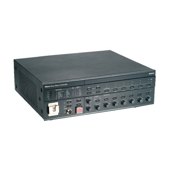
Page 12: Voice Alarm Controller
The six amplified by an external power amplifier. green LEDs indicate the zones in which a business call is running. Bosch Security Systems | 2005-04 | 9922 141 10364en... - Page 13 9 BGM tone controls - Two rotary knobs to control volume of the BGM in each zone. the high and low frequencies of the BGM (see section 5.4). Bosch Security Systems | 2005-04 | 9922 141 10364en...
- Page 14 39 PC Call station input - An input to connect a PC the voice alarm controller. Do not change the call station. Not for use in basic systems. positions of the switches. Bosch Security Systems | 2005-04 | 9922 141 10364en...
-
Page 15: Call Station
(no. 42). figure 2.4: Call Station The call station is not supervised. For compliance to evacuation standards, the Plena Voice Alarm System disables the call station during emergency calls. Bosch Security Systems | 2005-04 | 9922 141 10364en... -
Page 16: Overview
(LBB1990/00, see section 3.8). (see section 5.5). 4 Push-to-talk button - A push-to-talk (PTT) button to start the business call. Plena figure 2.5: Top and bottom views of the call station Bosch Security Systems | 2005-04 | 9922 141 10364en... -
Page 17: Installation
USB cable area. table 3.2: LBB1956/00 contents Description Quantity Call station Cat-5 cable Caution Keep the equipment boxed until the moment of installation. Boxed equipment is relatively well protected. Bosch Security Systems | 2005-04 | 9922 141 10364en... -
Page 18: Emergency Microphone
Alar m Zon e4 Zon e5 Zon e6 LBB1990/00 figure 3.2: Connecting the emergency microphone CD/Tuner figure 3.3: BGM inputs table 3.3: BGM inputs Input Source CD/Tuner CD or tuner Auxiliary source Bosch Security Systems | 2005-04 | 9922 141 10364en... -
Page 19: Call Station
24 V(DC) power source. See figure 3.5 for connection details. LBB1956/00 G ND G ND 100V 70V line in line out PLN-1P120 figure 3.6: Connecting an external power amplifier figure 3.5: Connecting a power supply Bosch Security Systems | 2005-04 | 9922 141 10364en... -
Page 20: Loudspeakers
100 V loudspeakers at 70 V is also 240 W. The external amplifier is used for calls only with 480 W output power and 100 V loudspeaker line voltage. figure 3.7: Connecting loudspeaker zones Bosch Security Systems | 2005-04 | 9922 141 10364en... -
Page 21: Volume Overrides
Z+ pin of the zone is internally connected to the NO contact of the Volume Override. So, the NC and the NO contacts determine which voltage is supplied to the positive pins of the override outputs (Z+). Bosch Security Systems | 2005-04 | 9922 141 10364en... - Page 22 24V contact of the Volume Override. LBB1990/00 Override/Trigger Output 100V Fault Call Volume Override TRG2 Override/Trigger Output 100V Fault Call Volume Override TRG2 figure 3. 1 0: 4-wire volume override Bosch Security Systems | 2005-04 | 9922 141 10364en...
-
Page 23: Line Output
Enable 3-wire volume override in the configuration software. Caution Make sure that the correct connections have been made and the system is correctly configured. 100V 100V figure 3. 1 1: 3-wire volume override Bosch Security Systems | 2005-04 | 9922 141 10364en... -
Page 24: Mic/Line Input With Vox Functionality
Installation and User Instructions (9922 141 1037x) for more information. Mic/Lin LBB1990/00 figure 3. 1 3: Mic/line input with VOX functionality DC out VOX Switch figure 3. 1 4: Connecting a VOX switch Bosch Security Systems | 2005-04 | 9922 141 10364en... -
Page 25: Status Output Contacts
100 - 120 115 V - 10 AT 220 - 240 230 V - 6.3 AT Note The LBB1990/00 Voice Alarm Controller is delivered with the voltage selector in the 230 position. Bosch Security Systems | 2005-04 | 9922 141 10364en... -
Page 26: 3.15.3 Back-Up Power
M e s s a g e M o n it o ri n g S p e a ke r figure 3. 1 7: Connecting the mains cord Bosch Security Systems | 2005-04 | 9922 141 10364en... -
Page 27: Configuration
(OFF). See section 4.5. 2ch operation Switches 2-channel operation on (ON) and off (OFF). See section 4.5. 1 1. Reserved Reserved. This DIP switch must always be in the OFF position. Bosch Security Systems | 2005-04 | 9922 141 10364en... -
Page 28: Supervision
Then, the program memory is checked and the processor resumes operation within 10 seconds. The indicator remains on until the fault is acknowledged and reset. Bosch Security Systems | 2005-04 | 9922 141 10364en... -
Page 29: Message Supervision
If supervision is enabled, the voice alarm controller continuously monitors all loudspeaker lines in the system for short-to-ground situations. If a leakage current > 30 + 15 mA is detected in a line, the line is considered faulty. Bosch Security Systems | 2005-04 | 9922 141 10364en... -
Page 30: Channel And 2 Channel Operation
BGM/Spare power amplifier 1 VOX activate by mic. VOX activate by VOX Switch External Call power amplifier 2 Speech filter Flat 3 Phantom power Off Phantom power On figure 4.5: VOX settings table Bosch Security Systems | 2005-04 | 9922 141 10364en... -
Page 31: Vox
ID of this call station is 1. This is accomplished by not accept phantom power, leave the switch in the OFF leaving the DIP switches 1 to 4 in the default OFF position. position. Bosch Security Systems | 2005-04 | 9922 141 10364en... -
Page 32: Sensitivity
The speech filter improves the speech intelligibility by cutting off the lower frequencies. 4.7.5 Termination Switch 8 must always be in the ON position, since basic systems contain only 1 call station. Bosch Security Systems | 2005-04 | 9922 141 10364en... -
Page 33: Operation
5.2: Power indicator Select Zone select CD/Tuner Note When the system is switched on for the first time and supervision is enabled, calibrate the system (see section 5.3). figure 5.3: BGM source selector Bosch Security Systems | 2005-04 | 9922 141 10364en... -
Page 34: Select Zones
(Zone select, see figure 5.4). Select Zone select CD/Tuner figure 5.5: BGM volume controls Bosch Security Systems | 2005-04 | 9922 141 10364en... -
Page 35: Business Calls
5. 1 : Call station status indicators Indicator Description Green PTT button is pushed. Yellow Fault in the system. Z1-Z6 System is in emergency state. The call station is disabled. figure 5.7: Zone select buttons Bosch Security Systems | 2005-04 | 9922 141 10364en... -
Page 36: Emergency State
5.9: Emergency button At the moment the emergency state is entered, a beeper starts and the EMG status output contact is closed. Note See section 5.6.4 for information about exiting the emergency state. Bosch Security Systems | 2005-04 | 9922 141 10364en... - Page 37 All call Alarm message Indicator test Alert message All call EMG mic Alarm message Indicator test EMG mic figure 5. 1 3: All call button figure 5. 1 5: Emergency microphone indicator Bosch Security Systems | 2005-04 | 9922 141 10364en...
-
Page 38: Distribute The Alert Message
Alert message All call Alarm message Indicator test EMG mic Fault Zone select Reset Zone1 Zone2 figure 5. 1 6: Zone select buttons figure 5. 1 8: Alert message button Bosch Security Systems | 2005-04 | 9922 141 10364en... -
Page 39: Distribute The Alarm Message
Acknowledge the fault state The beeper can be switched off by acknowledging the fault state with the Fault Ack button (see figure 5.20). Fault Zone select Reset Zone1 Zone2 figure 5.20: Fault Ack button Bosch Security Systems | 2005-04 | 9922 141 10364en... -
Page 40: Fault Indicators
EMG mic Zone4 Ground short Zone5 Input Router Zone6 figure 5.24: Disabled indicator The availability of the indicators can be tested with the Indicator test button (see figure 2.3, no. 11). Bosch Security Systems | 2005-04 | 9922 141 10364en... - Page 41 (see section 4.5). Router A router fault is detected. Contact your dealer. This fault should not occur, since this type of supervision is disabled (see section 4.5). Bosch Security Systems | 2005-04 | 9922 141 10364en...
- Page 42 Plena Voice Alarm System | Basic System Manual | Operation en | 42 Intentionally left blank Bosch Security Systems | 2005-04 | 9922 141 10364en...
-
Page 43: Technical Data
Maximum load means maximum power out, 2x redundant RJ45 sockets to connect the call station to the voice alarm controller with Cat-5 Ethernet maximum load 24 V(DC) out and maximum cables. number of call stations. Bosch Security Systems | 2005-04 | 9922 141 10364en... -
Page 44: Message Manager
Signal-to-noise ratio (flat at max. volume): Floating, max. 250 V > 85 dB Current: Supervision: max. 0.5 A 20 kHz pilot tone Outputs: 70, 100 V screw terminal, 100 V call out Bosch Security Systems | 2005-04 | 9922 141 10364en... -
Page 45: Trigger Inputs/24 V Dc Out
3-pin XLR, 6.3 mm jack socket, balanced Nominal output level: Maximum output level: 6.2.12 External power amplifier Type: 3-pin XLR and screw terminals Controller output/External power amplifier input voltage: Controller input/External power amplifier output voltage: 100 V Bosch Security Systems | 2005-04 | 9922 141 10364en... - Page 46 Plena Voice Alarm System | Basic System Manual | Technical Data en | 46 Intentionally left blank. Bosch Security Systems | 2005-04 | 9922 141 10364en...
-
Page 47: Glossary
PCs. Voice-activated. The voice alarm controller has one voice-activated input to connect an additional emergency microphone or to interface with another emergency sound system (e.g. a Praesideo system). Bosch Security Systems | 2005-04 | 9922 141 10364en... - Page 48 Plena Voice Alarm System | Basic System Manual | Glossary en | 48 Intentionally left blank. Bosch Security Systems | 2005-04 | 9922 141 10364en...
-
Page 49: Product Index
Same as remote control extension, but with rugged connectors LBB1956/00 Call station Based on existing LBB1946 with 6 zone keys and all call LBB1957/00 Call station keypad Call station keypad extension with 7 zone keys Bosch Security Systems | 2005-04 | 9922 141 10364en... - Page 50 Plena Voice Alarm System | Basic System Manual | Product Index en | 50 Intentionally left blank. Bosch Security Systems | 2005-04 | 9922 141 10364en...
- Page 52 For more information visit www.boschsecuritysystems.com © Bosch Security Systems B.V. Data subject to change without notice 2005-04 | 9922 141 10364en...