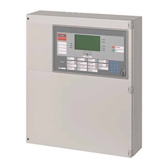
Siemens FC700A Hardware Description
Fire detection system
Hide thumbs
Also See for FC700A:
- System planning manual (70 pages) ,
- Installation and hardware commissioning (38 pages) ,
- Maintenance instructions manual (20 pages)

Related Manuals for Siemens FC700A


Summary of Contents for Siemens FC700A
- Page 1 FC700A Fire detection system Hardware description Modules Fire & Security Products Siemens Building Technologies...
- Page 2 Sous réserve de modifications techniques et de la disponibilité. © 2004 Copyright by Siemens Building Technologies AG Wir behalten uns alle Rechte an diesem Dokument und an dem in ihm dargestellten Gegenstand vor. Der Empfänger anerkennt diese Rechte und wird dieses Dokument nicht ohne unsere vorgängige schriftliche Ermächtigung ganz oder teilweise Dritten zugänglich machen oder außerhalb des Zweckes verwenden, zu dem es ihm übergeben worden ist.
-
Page 3: Table Of Contents
Line voltage.....................33 Line termination element (Application see chapter 9.2)......33 Compatibility (detector <–> line type) .............33 Important components ................34 Programming switch ”S3”................34 Connections ....................35 Connection "Collective" SynoLINE600/-Ex ..........36 E3M111 Line module ”SynoLOOP”.............37 Siemens Building Technologies 007831_a_en_--.doc Fire & Security Products 03.2004... - Page 4 E3L030 Control module VdS ..............60 15.1 Overview ....................60 15.2 Application....................60 15.3 Key data ....................60 15.4 Important components ................61 15.5 Programming switch ”S3”................62 15.6 Special functions ..................62 15.7 Connections ....................63 E3G050 Control module ”Contacts” ...........64 Siemens Building Technologies 007831_a_en_--.doc Fire & Security Products 03.2004...
- Page 5 22.1 Overview ....................85 22.2 Application....................85 22.3 Key data ....................85 22.4 Wiring principle..................86 22.5 Mechanical design ..................86 22.6 Important components ................87 22.7 Programming switch ”S1”................87 22.8 Connections ....................88 K3G060 Relay card ................89 Siemens Building Technologies 007831_a_en_--.doc Fire & Security Products 03.2004...
- Page 6 Application.....................100 26.3 Mechanical design ................101 26.4 Important components B3Q580, B3Q590, B3Q595 ......101 26.5 Programming switch ”S3”..............102 26.6 Message presentation................103 26.7 Country specific configuration data............104 26.8 Connections B3Q580 ................107 26.9 Connections B3Q590/B3Q595..............107 Siemens Building Technologies 007831_a_en_--.doc Fire & Security Products 03.2004...
-
Page 7: About This Document
About this document Purpose This document describes the function of hardware modules of the control unit FC700A. The consistent adherence to these instructions is a prerequisite for a safe application. Scope This document contains information for all modules FC700A, valid for all software versions. - Page 8 Disregard of the safety regulations Before they are delivered, products are tested to ensure they function correctly when used properly. Siemens disclaims all liability for damage or injuries caused by the incorrect application of the instructions or disregard of warnings of danger contained in the documentation.
-
Page 9: Safety Regulations
The symbols listed below indicate the nature and origin of the danger. Signal word General danger Signal word Electrical voltage Example for a danger warning DANGER Disconnect the module from power supply. External voltage Siemens Building Technologies 007831_a_en_--.doc Fire & Security Products 03.2004... -
Page 10: Classification And Meaning Of Additional Symbols
This espe- cially applies when switching-off system components. In the case of extinguishing systems, always use the ”General installation in- structions” as a guideline. This guideline is available on request. Siemens Building Technologies 007831_a_en_--.doc Fire & Security Products 03.2004... - Page 11 Batteries require environmentally safe disposal. They must be handed in at the local collecting points. Please take into account that the extinguishing agent cylinders are pressurized and must be exchanged in compliance with the local safety regulations. Siemens Building Technologies 007831_a_en_--.doc Fire & Security Products 03.2004...
-
Page 12: Hardware Overview
SynoLINE600 SynoLOOP SynoLINE600-Ex B3Q580/ B3Q590/ Control modules I-Bus E3G050 E3L020 E3G070 E3L030 E3G060 Treiber 1..16 1...8 1..6 Z3B171 Z3B171 250V 250V FBF FSD ÜE FÜ Fire control Fire control installations installations Siemens Building Technologies 007831_a_en_--.doc Fire & Security Products 03.2004... - Page 13 Remote transmission equipment Fire department control panel (VdS ’D’) Fire department key cabinet (VdS ’D’) ÜE Transmission device (VdS ’D’) 3rd party products not listed in this document, see chapter 15 Siemens Building Technologies 007831_a_en_--.doc Fire & Security Products 03.2004...
- Page 14 B3R051 30VDC / 1A Printer Gateway FG700A B3D021 C-Bus FT700A E3I020 RS232 E3H020 Building Management System (ISO1745 protocol) Power supply with accessories Mains FC700A Batteries B2F020 E3C011 AX12.. 29,6V/6A B3Q700 I-Bus Siemens Building Technologies 007831_a_en_--.doc Fire & Security Products 03.2004...
- Page 15 Printer Module Specification E3I020 RS232 module Gateway Module Specification E3H020 C-Bus Gateway module Power supply with accessories Module Specification B2F020 Converter 115/230V 29,6V / 6A as system voltage E3C011 Battery-charging module Siemens Building Technologies 007831_a_en_--.doc Fire & Security Products 03.2004...
-
Page 16: Emergency Operation
– Emergency operation circuit at C-Bus level (external) Comprises the functions ”Collective alarm” and ”Silence alarm horns” – Requires 3 additional wires between FC700A and FT700A – The line ’Emergency operation circuit fire alarm’ is electrically monitored – Function ’Monitoring’ must, if not used, be set to inactive (SWE700A) –... -
Page 17: Emergency Operation At Line Module E3M111 Level
Operation also in emergency mode (= 3 additional wires for emergency operation between CPU and control consoles) Second de-coupled 24V supply (= 3 additional wires if there is no autono- mous power supply) Siemens Building Technologies 007831_a_en_--.doc Fire & Security Products 03.2004... - Page 18 Emergency operation circuit and the emergency power supply are not laid out as a loop line – Route emergency power supply in a separate cable or in the C-Bus cable feedback – Siemens Building Technologies 007831_a_en_--.doc Fire & Security Products 03.2004...
-
Page 19: Principle Of 24V Wiring
Supply modules B3Q700 (FC) B3Q700 B3Q700 (FC) (FT) Plug-in-terminals K7 Plug-in-terminals K7 Programming terminals 'K7' as Input: = 0 -Resistors X31+X32+X33+X34 Ω Programming terminals 'K7' as Output: = 0 -Resistors Y31+Y32+Y33+Y34 Ω Siemens Building Technologies 007831_a_en_--.doc Fire & Security Products 03.2004... -
Page 20: Cascading Principle
Principle of 24V wiring Cascading principle Standard power supply Mains B2F020 E3C011 Battery 1 max. 27Ah Cascading Mains B2F020 E3C011 Battery 2 max. 27Ah Auxiliary power supply operating in parallel Siemens Building Technologies 007831_a_en_--.doc Fire & Security Products 03.2004... -
Page 21: Ground Fault Monitoring (Fm Compliance)
The basic FM requirement is to safely monitor and detect ground faults, of all lines leaving the panel. The FC700A has been technically adjusted to fulfil those requirements. For FM installations, adhere the FM Approval mark to the control unit housing next to APPROVED the type label. -
Page 22: Programming Ground Fault Monitoring
- If galvanically isolated relays are used, make sure that the 3rd party system takes over the ground fault monitoring function. Ground fault monitoring reacts if the resistance is: a) 4k from positive potential to ground, or ≤ Ω 16k from negative potential (system ground) to ground ≤ Ω Siemens Building Technologies 007831_a_en_--.doc Fire & Security Products 03.2004... -
Page 23: E3C011 Battery Charging Module
- for the connection of the prefabricated cable for battery, temperature sensor and power unit E3C011 Battery terminals (+, -, Centre tap) Temperature sensor Card chassis - mounted on module chassis Siemens Building Technologies 007831_a_en_--.doc Fire & Security Products 03.2004... -
Page 24: Important Components
FG... ”S2” is set to variant 11 (ALARMCOM) at the factory Floating charge voltage as a function of temperature, or for diagrams of the various types of battery see page 25 Siemens Building Technologies 007831_a_en_--.doc Fire & Security Products 03.2004... -
Page 25: Programming Switch "S3
The I-Bus address setting is given as default by the tool (SWE700A) as address 16, therefore the programming switch 'S3' of the E3C011 must be set accordingly. Floating charge voltage as a function of temperature Siemens Building Technologies 007831_a_en_--.doc Fire & Security Products... - Page 26 E3C011 Battery charging module Siemens Building Technologies 007831_a_en_--.doc Fire & Security Products 03.2004...
-
Page 27: Led Indicator Block "Battery-Charger
LED ”Power supply fault” external voltage Input voltage > 31.0V → power unit malfunction – – EEPROM check sum error LED ”Power on” – Input voltage > 28.5V LED ”Battery fault” – no function Siemens Building Technologies 007831_a_en_--.doc Fire & Security Products 03.2004... -
Page 28: Connections
2) Function "24V external voltage" or "without battery" can be programmed via maintenance PC With the function "external voltage", battery presence monitoring can be programmed as "active" (i.e. the external voltage is monitored). Siemens Building Technologies 007831_a_en_--.doc Fire & Security Products... -
Page 29: B2F020 Converter
Parallel operation Switches on primary side With metal shielding Dimensions 200 x 100 x 40 Power supply general The power supply for fire control unit FC700A consists of the following three com- ponents: Converter B2F020 – Battery-charging module E3C011 –... -
Page 30: Important Components
Check mains voltage setting before commissioning The converter is supplied by the factory at 230V To switchover to 115V remove metal shield (remove screws ) and then plug in jumper at the ”115V ” pin Siemens Building Technologies 007831_a_en_--.doc Fire & Security Products 03.2004... -
Page 31: Connections
Batteries larger than 27Ah per E3C011 are impossible if the recharging of a bat- – tery is to be done according to regulations (to 80% capacity within 24h) See page 20 for interconnection principle – Siemens Building Technologies 007831_a_en_--.doc Fire & Security Products 03.2004... -
Page 32: E3M080 Line Module "Collective
4,5mA during AI ”dark” phase Line voltage limit 26,5 ... 27,7V Quiescent line current max. 4,5mA Reset time 3 sec. Turn-on alarm delay 4.6 sec. Fault delay 15 sec. Module quiescent current at 24V 85mA Siemens Building Technologies 007831_a_en_--.doc Fire & Security Products 03.2004... -
Page 33: Line Voltage
20V Ex detectors (without restrictions) used via DC1192 with SB3: DO1101-Ex, DT110x-Ex Line termination with Line type 1 Special detectors: DLO1191, (with mixed lines also OP620C, HI62xC, DM110x, DC1192) EOL22 (Ex) Siemens Building Technologies 007831_a_en_--.doc Fire & Security Products 03.2004... -
Page 34: Important Components
I-Bus devices. Function / I-Bus address Programming switch S3 S3-1 S3-2 S3-3 S3-4 S3-5 S3-6 Module out of commission (unused) I-Bus user number ”S3-1...6” are set to ”off” at the factory Siemens Building Technologies 007831_a_en_--.doc Fire & Security Products 03.2004... -
Page 35: Connections
I-Bus modules Data communication I-Bus modules to other I-Bus modules 1) Local ground connection 2) To read in technical alarms. Do not mix with detectors on the same line Siemens Building Technologies 007831_a_en_--.doc Fire & Security Products 03.2004... -
Page 36: Connection "Collective" Synoline600/-Ex
DM1103+ DFB1190 DMZ1197-AD - + - + - + - + - + - + EOL22Ex Load factor for collective elements SynoLINE600 (limited by 25 per line) Details see document 007836 Siemens Building Technologies 007831_a_en_--.doc Fire & Security Products 03.2004... -
Page 37: E3M111 Line Module "Synoloop
According to EN54, a ”simple error” may not cause the malfunction of more than 32 detectors. After the short circuit the line automatically reverts to ”Normal operating condition”. Siemens Building Technologies 007831_a_en_--.doc Fire & Security Products... -
Page 38: Important Components
I-Bus devices. Function / I-Bus address Programming switch S3 S3-1 S3-2 S3-3 S3-4 S3-5 S3-6 Module out of commission (unused) I-Bus user number ”S3-1...6” are set to ”off” at the factory Siemens Building Technologies 007831_a_en_--.doc Fire & Security Products 03.2004... -
Page 39: Connections
I-Bus module E3G070 Plug-in terminals blue Supply for blue I-Bus modules to other I-Bus module green Double flat cable header from I-Bus module E3G070 Data communication I-Bus modules to other I-Bus module Siemens Building Technologies 007831_a_en_--.doc Fire & Security Products 03.2004... -
Page 40: Connection "Addressable" Synoloop
30V/1A EB322A AB322A 30V/1A free terminals CO NC NO CO NN 4k75 4k75 rear end APMK Load factor for addressable elements SynoLOOP (limited by 128 per loop) Details see document 007836 Siemens Building Technologies 007831_a_en_--.doc Fire & Security Products 03.2004... -
Page 41: Connection "Conventional" Synoline300
OH320C conventional HI320A/322A EOL22(Ex) micro terminals Response indicator AI322 AI320 AI300 AI322 max. 2 response indicator Load factor for conventional elements SynoLINE300 (limited by 32 per line) Details see document 007836 Siemens Building Technologies 007831_a_en_--.doc Fire & Security Products 03.2004... -
Page 42: Connection "Collective" Synoline600
- + - + - + - + - + - + KMK=25 EOL22(Ex) Linear smoke detector Response indicator AI300 AI340 Load factor for collective elements SynoLINE600 (limited by 25 per line) Details see document 007836 Siemens Building Technologies 007831_a_en_--.doc Fire & Security Products 03.2004... -
Page 43: Connection "Collective" Synoline600-Ex
DM1103+ DFB1190 DMZ1197-AD - + - + - + - + - + - + EOL22Ex Load factor for collective elements SynoLINE600-Ex (limited by 25 per line) Details see document 007836 Siemens Building Technologies 007831_a_en_--.doc Fire & Security Products 03.2004... -
Page 44: E3I040 I-Bus/Lon Module
I-Bus address is set at programming switch ”S3” Only one module per station possible 11.2 Application Required for all LON applications within FC700A, such as: LON-I/O p.c.b. K3I110 – LON/Mimic Display converter K3I050 with Mimic display drivers K3R072 (or –... -
Page 45: Wiring Principle
EOL resistor R60 on E3I040 has to be changed to 50Ω (e.g. use 2 resistors of 100Ω in parallel circuit). T-taps are only possible from the terminal blocks of the LON-Bus devices. Siemens Building Technologies 007831_a_en_--.doc Fire & Security Products... -
Page 46: Important Components
I-Bus devices. Function / I-Bus address Programming switch S3 S3-1 S3-2 S3-3 S3-4 S3-5 S3-6 Module out of commission (not used) I-Bus device number ”S3-1...6” are set to ”off” at the factory Siemens Building Technologies 007831_a_en_--.doc Fire & Security Products 03.2004... -
Page 47: Connections
I-Bus modules Plug-in terminals blue Supply blue to other I-Bus modules I-Bus modules green Double flat cable header from previous I-Bus modules Data communication I-Bus modules to other I-Bus modules Siemens Building Technologies 007831_a_en_--.doc Fire & Security Products 03.2004... -
Page 48: E3I020 Rs232 Module
Communication and supply via flat cable Card format 100mm x 160mm 12.2 Application Two application possibilities are provided: a) Installation in the control unit FC700A b) Installation at the rear of the control terminal FT700A Application a) 2 RS232 interfaces from B3Q700 (FC700A) –... -
Page 49: Wiring Principle
(ground 1) 0V1 (transmit) TXD2 (receive) RXD2 RTS2 Modem CTS2 RS232-2 extended TCLK2 functions (SWE700A) RCLK2 (ground 2) 0V2 Depending on type of modem the signals 'RTS/CTS' must not be wired Siemens Building Technologies 007831_a_en_--.doc Fire & Security Products 03.2004... -
Page 50: Important Components
E3I020 RS232 module 12.6 Important components Installation in control unit FC700A Terminal block (supplied with Z1I030) Flat cable F20A140 for applica tion in control unit to B3Q700 E3I020 connector "ST2" Connector "ST1": RS232 (2 x HCMOS level) Connector "ST2": for the insertion of a plug-in terminal block Plug-in terminals for "ST2"... -
Page 51: E3H020 C-Bus Gateway
Station type FG700A Download of FG configuration data necessary Processing capacity see document 007836 Automatic data transfer of all FC700A to FG700A in the start-up phase – For FG700A → CKQ007.60 (EPROM Set 2x 512Kx8Bit) – Install in the fire detection control unit FC700A –... -
Page 52: Wiring Principle
Wiring principle Fire detection control unit C-Bus 24V/5VDC E3H020 I-BUS FC700A ISO 1745 Protocol RS232 Lines Control modules Detectors 13.5 Supply wiring principle C-Bus E3H020 24V/5VDC Supply I-Bus I-Bus Data communication Siemens Building Technologies 007831_a_en_--.doc Fire & Security Products 03.2004... -
Page 53: Important Components
Programming of X1: ”FG” + supply from control unit (Input) (X1-17.. 20) X15 + X16 + X17 + X18 ”FG” + autonomous supply (Output) (X1-17.. 20) Y15 + Y16 + Y17 + Y18 Siemens Building Technologies 007831_a_en_--.doc Fire & Security Products 03.2004... -
Page 54: Programming Switches "S1" + "S2
Interfaces RS232-1 and RS232-2, via terminal block ”X2” (internal modem). Programming switch Interface Application S5-1 S5-2 RS232-1 internal modem via terminal block ”X2” – RS232–2 (Service port) internal modem via terminal block ”X2” – Set to ”off” at factory Siemens Building Technologies 007831_a_en_--.doc Fire & Security Products 03.2004... -
Page 55: Connections
Jumper must always be inserted (inserted at factory) 24V OUT 1) Configuration as In-/or output see also jumpers X15, X16, X17, X18, Y15, Y16, Y17, Y18 table in chapter Important components Siemens Building Technologies 007831_a_en_--.doc Fire & Security Products 03.2004... - Page 56 I-Bus modules I-Bus modules green Double flat cable header from previous I-Bus modules Data communication I-Bus modules to other I-Bus modules Flat cable header unused Interface asynchronous TTL Siemens Building Technologies 007831_a_en_--.doc Fire & Security Products 03.2004...
-
Page 57: E3L020 Control Module "I/O
- mounted on module chassis - for the connection of the prefabricated cable to connection level, or - for direct connection of the periphery E3L020 Card chassis - mounted on module chassis Siemens Building Technologies 007831_a_en_--.doc Fire & Security Products 03.2004... -
Page 58: Important Components
I-Bus devices. Function / I-Bus address Programming switch S3 S3-1 S3-2 S3-3 S3-4 S3-5 S3-6 Module out of commission (unused) I-Bus user number ”S3-1...6” are set to ”off” at the factory Siemens Building Technologies 007831_a_en_--.doc Fire & Security Products 03.2004... -
Page 59: Connections
I-Bus modules Plug-in terminals blue Supply for blue I-Bus modules to other I-Bus modules green Double flat cable header from previous I-Bus modules Data communication I-Bus modules to other I-Bus modules Siemens Building Technologies 007831_a_en_--.doc Fire & Security Products 03.2004... -
Page 60: E3L030 Control Module Vds
10Ω per wire* Line resistance for SST max. 10Ω per wire* Control output load max. 40mA with EMI protection Quiescent current at 24V 18mA (normal operating mode) * For details see page 63 Siemens Building Technologies 007831_a_en_--.doc Fire & Security Products 03.2004... -
Page 61: Important Components
Module supply remove depending on 3rd party Fuse with high breaking capacity (sand-filled) extinguishing system Plug-in terminals "K1": Programming switch "S3": Supply for "I-Bus" modules Setting "I-Bus address" (see chapter Programming switch) Siemens Building Technologies 007831_a_en_--.doc Fire & Security Products 03.2004... -
Page 62: Programming Switch "S3
Indicator ”LEDs 5, 6, 7, T5 operational” ● Function ”Silence audible signal” ● ● ÜE Function ”Activate ÜE” ● ● Function ”Activate FSD unlocking” ● ● SST (Extinguishing standard interface) TK (Door switch control unit) ● Siemens Building Technologies 007831_a_en_--.doc Fire & Security Products 03.2004... -
Page 63: Connections
I-Bus modules blue blue Supply for to other I-Bus modules I-Bus modules green Double flat cable header from previous I-Bus modules Data communication I-Bus modules to other I-Bus modules Siemens Building Technologies 007831_a_en_--.doc Fire & Security Products 03.2004... -
Page 64: E3G050 Control Module "Contacts
- mounted on module chassis - for the connection of the prefabricated cable to connection level, or - for direct connection of the periphery E3G050 Card chassis - mounted on module chassis Siemens Building Technologies 007831_a_en_--.doc Fire & Security Products 03.2004... -
Page 65: Important Components
I-Bus devices. Function / I-Bus address Programming switch S3 S3-1 S3-2 S3-3 S3-4 S3-5 S3-6 Module out of commission (unused) I-Bus user number ”S3-1...6” are set to ”off” at the factory Siemens Building Technologies 007831_a_en_--.doc Fire & Security Products 03.2004... -
Page 66: Connections
I-Bus modules Plug-in terminals blue Supply for blue I-Bus modules to other I-Bus modules green Double flat cable header from previous I-Bus modules Data communication I-Bus modules to other I-Bus modules Siemens Building Technologies 007831_a_en_--.doc Fire & Security Products 03.2004... -
Page 67: E3G060 Control Module "Monitored
- mounted on module chassis - for the connection of the prefabricated cable to connection level, or - for direct connection of the periphery E3G060 Card chassis - mounted on module chassis Siemens Building Technologies 007831_a_en_--.doc Fire & Security Products 03.2004... -
Page 68: Important Components
I-Bus devices. Function / I-Bus address Programming switch S3 S3-1 S3-2 S3-3 S3-4 S3-5 S3-6 Module out of commission (unused) I-Bus user number ”S3-1...6” are set to ”off” at the factory Siemens Building Technologies 007831_a_en_--.doc Fire & Security Products 03.2004... -
Page 69: Programming Switches "S7" & "S8
Switch ”S7” defines global horn mode for all horn outputs. Invert this mode (constant / intermitted) individually for each horn output by connecting common (X1-1) with corresponding control input (X1-15.. 20). Siemens Building Technologies 007831_a_en_--.doc Fire & Security Products 03.2004... -
Page 70: Connections
24V / 12A Double flat cable header from previous I-Bus modules Data communication I-Bus modules to other I-Bus modules 1) The indicated polarity at the terminals 2...14 applies to the active state Siemens Building Technologies 007831_a_en_--.doc Fire & Security Products 03.2004... -
Page 71: E3G070 Control Module "Universal
- mounted on module chassis - for the connection of the prefabricated cable to connection level, or - for direct connection of the periphery E3G070 Card chassis - mounted on module chassis Siemens Building Technologies 007831_a_en_--.doc Fire & Security Products 03.2004... -
Page 72: Important Components
”S3-1...6” are set to ”off” at the factory The I-Bus address setting is given as default by the tool (SWE700A) as address 15, therefore the programming switch 'S3' of the E3G070 must be set accordingly. Siemens Building Technologies 007831_a_en_--.doc Fire & Security Products... -
Page 73: Connections
I-Bus module E3M111 1) The indicated polarity at the terminals 5...8 applies to the active state 2) The output X1-9,10 is always monitored 3) Terminate not used horn lines with a 4,75kΩ resistor Siemens Building Technologies 007831_a_en_--.doc Fire & Security Products 03.2004... -
Page 74: Z3B171 Relay Module
External voltage side (contact) Control unit voltage side (coil) 19.1 Connections Z3B171 e.g. e.g. 900Ω E3G070/Q3 air conditioning control 10A 250VAC Terminal layout Relay Siemens Building Technologies 007831_a_en_--.doc Fire & Security Products 03.2004... -
Page 75: B3Q700 Control Terminal To Fc/Ft
Principle of the insertable inscription strips see page 77 20.1 Overview Control terminal for the fire control unit FC700A Becomes at the same time used as ’main-CPU’ For full system operating Can be used for single or multi AREA operating... -
Page 76: Application
’FC700A’ B3Q700 FT700A-1 -> CTY00760 international 1) FC700A-1 -> CIY00760 international 1) Default programming at factory by using it as spare part for FC700A, the file CIY00760 must be downloaded. The Flash program files are available from the Hotline. 20.4... -
Page 77: Mechanical Design
Mounting see document no. 007827 Foil Cover frame Display Protective cover Plexiglass door H26T030 Insertable inscription strips Adapter Z3I530, flat cable -> terminals: (Option) Connection outside housing to the parallel indicator panel B3R051 etc. Siemens Building Technologies 007831_a_en_--.doc Fire & Security Products 03.2004... -
Page 78: Important Components
X31 + X32 + X33 + X34 ”FC” + autonomous supply (Output) Y31 + Y32 + Y33 + Y34 If the control terminal B3Q700 is used as replacement for FC700A -> change the 0Ω−Resistors from pos. X31…..X34 to pos. Y31….Y34 Siemens Building Technologies 007831_a_en_--.doc... -
Page 79: Programming Switch 'S5
C-Bus participants are connected 2) Configuration as in-/or output see jumpers X31, X32, X33, X34, Y31, Y32, Y33, Y34 on table in chapter important components Siemens Building Technologies 007831_a_en_--.doc Fire & Security Products... -
Page 80: Connectors
Data bus to parallel indicator panel, Mimic display board external housing connection Parallel branching via adapter Z3I530 admissible Connector LCD illumination to LCD illumination Connector unused 3rd voltage source Connector unused FBA-CH Siemens Building Technologies 007831_a_en_--.doc Fire & Security Products 03.2004... -
Page 81: B3R051 Parallel Indicator Panel
”Lamp test” is contained in the menu function of control terminal B3Q700 21.2 Application Installation The parallel indicator panel B3R051 fits in the following housings: Control unit housing FC700A – Plastic housing ”small” H23G220 (1x B3R051) – Housing H28G200 with cover H28T110 for 1x B3R051 and B3Q700 –... -
Page 82: Wiring Principle
Z3I350 24V supply line Note: max. 24 units B3R051 or K3R072 (also mixed) possible with max. 8 different addresses – remove resistor array (see page 83) except on one unit – Siemens Building Technologies 007831_a_en_--.doc Fire & Security Products 03.2004... -
Page 83: Mechanical Design
Supply input 9...45VDC Plug-in terminals "K2", 6-pin: Connection of data bus instead of flat cable Programming switch "S1": Equipment address setting (see chapter Programming Plug-in terminals "K1", 4-pin: B3R051 switch) Power supply Siemens Building Technologies 007831_a_en_--.doc Fire & Security Products 03.2004... -
Page 84: Programming Switch "S1
B3Q700, ST4 Data bus (via flat cable) from K3I050, ST2 Flat cable header Data bus (via flat cable) to other B3R051/K3R072 Note: Remove eventually resistor array. Must be assembled for device! Siemens Building Technologies 007831_a_en_--.doc Fire & Security Products 03.2004... -
Page 85: K3R072 Mimic Display Board
49+50 for 'LED operation' LED 25..48 K3R072 wires 49+50 unused K3R072 These in-/outputs can be in Key 'Switch-off buzzer' parallel with other K3R072 Key 'Lamp test' if located in same cabinet Buzzer Z3I520 Siemens Building Technologies 007831_a_en_--.doc Fire & Security Products 03.2004... -
Page 86: Wiring Principle
24 LEDs connection of data bus wire 49= - outside housing wire 50= + K3R072 Electronics board Flat cable F12A100 (length 0,4m) / F12A470 (length 1,5m): connection of data bus inside housing Siemens Building Technologies 007831_a_en_--.doc Fire & Security Products 03.2004... -
Page 87: Important Components
Programming switch S1 S1-1 S1-2 S1-3 S1-4 Test procedure In this setting all outputs are activated alternating between even and uneven numbers. Equipment address ”S1-1...4” are set to ”off” at the factory Siemens Building Technologies 007831_a_en_--.doc Fire & Security Products 03.2004... -
Page 88: Connections
Z3I520 Connector Short-circuit proof Output for buzzer inputs/outputs only Buzzer max. 12mA / 24V inside housing application Connector Input lamp test Key 'Lamp test' Connector Input switch-off buzzer Key 'Switch-off buzzer' Siemens Building Technologies 007831_a_en_--.doc Fire & Security Products 03.2004... -
Page 89: K3G060 Relay Card
K3G060 23.3 Wiring principle external potential external potential Relay outputs Data bus (V+/V-) Relay outputs (V+/V-) K3R072 K3G060 K3G060 ST11 ST12 0,25m 0,25m Data bus relay Data bus relay activation activation Siemens Building Technologies 007831_a_en_--.doc Fire & Security Products 03.2004... -
Page 90: Mechanical Design
Jumper open: are set to NEUTRAL at the factory Terminal block "K2": Relay output channels 1..24 Connector 50-pin "ST1" with flat cable (length 0,25m) Possibility to connect V+ / V- potential Siemens Building Technologies 007831_a_en_--.doc Fire & Security Products 03.2004... -
Page 91: Connections
X1..X24 are set to NEUTRAL at the factory max. 30V / 1A Rel.24 Channel 24 Terminals external potential (switchable via jumper X1..X24) Flat cable header ST1 from K3R072 'ST11' or 'ST12' Energizing relays 1..24 Siemens Building Technologies 007831_a_en_--.doc Fire & Security Products 03.2004... -
Page 92: K3I050 Mimic Display Converter
-remains active until input 'buzzer OFF' is activated or the cause for a) or b) no longer exists Input 'lamp test' -activates all LED outputs within the K3R072, B3R051 for apprx. 2 sec. Siemens Building Technologies 007831_a_en_--.doc Fire & Security Products... -
Page 93: Mechanical Design
Service key (not used) Plug-in connector "X8": Buzzer off key input Plug-in connector "X9": Fuse "F1" 1,0A/T: Plug-in terminals "K1"; 6-pin: Lamp test key input for supply input 9..45VDC Module supply and LON-Bus Siemens Building Technologies 007831_a_en_--.doc Fire & Security Products 03.2004... -
Page 94: Programming Switch "S3
Maximum 32 LON-Bus devices. Function / LON-Bus address Programming switch S3 S3-1 S3-2 S3-3 S3-4 S3-5 S3-6 Module out of commission (not used) LON-Bus device number ”S3-1...6” are set to ”off” at the factory Siemens Building Technologies 007831_a_en_--.doc Fire & Security Products 03.2004... -
Page 95: Connections
Buzzer output buzzer max. 50mA / 22V Plug-in connector operation LED Operation LED output Plug-in connector Buzzer off key input key 'buzzer off' Plug-in connector key 'lamp test' Lamp test key input Siemens Building Technologies 007831_a_en_--.doc Fire & Security Products 03.2004... -
Page 96: K3I110 Lon I/O P.c.b
* all relay activated incl. service LED 25.4 Wiring principle max. length of LON-Bus 1000m LON-Bus E3I040 B3Q590/ K3I050 B3Q580 K3I110 Data bus 16 programmable control outputs max. 30V /1A 16 programmable monitored control inputs Siemens Building Technologies 007831_a_en_--.doc Fire & Security Products 03.2004... -
Page 97: Mechanical Design
= not monitored (factory setting) left = monitored Key 'S2': Service press 2 seconds to initiate lamp test (LED and relay), each relay and/or LED (H1...H16) is activated one after the other Siemens Building Technologies 007831_a_en_--.doc Fire & Security Products 03.2004... -
Page 98: Programming Switch 'S3
Programming switch ’S3’ Function / LON-Bus address Programming switch S3 S3-1 S3-2 S3-3 S3-4 S3-5 S3-6 Module out of commission (not used) LON-Bus device number ”S3-1...6” are set to ”off” at the factory Siemens Building Technologies 007831_a_en_--.doc Fire & Security Products 03.2004... -
Page 99: Connections
4k75 control input 15 programmable monitored control input 16 from E3I040 or from previous LON device Plug-in terminals K1 not used Supply 9...45VDC 24V supply Earth LON-Bus to other LON device Siemens Building Technologies 007831_a_en_--.doc Fire & Security Products 03.2004... -
Page 100: B3Q580 Floor Repeater Panel And B3Q590/B3Q595 Floor Repeater Panel With Control Functions
16mA 45V max. 90mA 90mA 9V quiescent (LCD backlight off) 50mA 35mA 9V max. 480mA 500mA 26.2 Application B3Q580: Typical floor indication panel B3Q590 / B3Q595: Secondary indication and operating panel Siemens Building Technologies 007831_a_en_--.doc Fire & Security Products 03.2004... -
Page 101: Mechanical Design
LON-Bus (see E3I040 chapter for operating access: Plug-in terminals "K2": Principle wiring) - B3Q590: Nordic fire brigade key switch Programming inputs for - B3Q595: KABA fire brigade key switch indication fields (LEDs) Siemens Building Technologies 007831_a_en_--.doc Fire & Security Products 03.2004... -
Page 102: Programming Switch "S3
Maximum 32 LON-Bus devices. Function / LON-Bus address Programming switch S3 S3-1 S3-2 S3-3 S3-4 S3-5 S3-6 Module out of commission (not used) LON-Bus device number ”S3-1...6” are set to ”off” at the factory Siemens Building Technologies 007831_a_en_--.doc Fire & Security Products 03.2004... -
Page 103: Message Presentation
1 ----> <-tx1->xxx Special function: <--------- customer text 2 ---------> – different display mode nn%<--------- customer text 1 ---------> A = on alarm <--------- customer text 2 ---------> B = on fault Siemens Building Technologies 007831_a_en_--.doc Fire & Security Products 03.2004... -
Page 104: Country Specific Configuration Data
31.12.2000 Time format: 23:59 Time format: 23.59 National characters: ƒ ‰ ÷ ˆ ‹ ¸ ≈ Â È § \ National characters: ∅ ¯ ∆ Ê ≈ Â \ ° ~ Siemens Building Technologies 007831_a_en_--.doc Fire & Security Products 03.2004... - Page 105 Date format: 31.12.2000 Time format: 23:59 Time format: 23:59 National characters: È Ì ˚ ¸ ı Û ˆ \ ~ Ë Ï Ú ∅ ¯ š ý National characters: \ ° Siemens Building Technologies 007831_a_en_--.doc Fire & Security Products 03.2004...
- Page 106 Date format: 31-12-2000 Date format: 31-12-2000 Time format: 23:59 Time format: 23:59 National characters: £ \ ~ National characters: ¡ ∆ Ð … Õ ” ÷ ⁄ Ý Þ \ ° Siemens Building Technologies 007831_a_en_--.doc Fire & Security Products 03.2004...
-
Page 107: Connections B3Q580
LON device Terminal block Input programmable LED 3 Use ground potential to control inputs (if input is connected to ground, LED is active) Input programmable LED 2 Input programmable LED 1 Siemens Building Technologies 007831_a_en_--.doc Fire & Security Products 03.2004... - Page 108 Siemens Building Technologies AG Alte Landstr. 411 CH-8708 Männedorf Tel. +41 1 - 922 6111 Fax +41 1 - 922 6450 www.sibt.com Document no. 007831_a_en_-- Manual FC700 Edition 03.2004 Section 3...