ABB ACS310 User Manual
Hide thumbs
Also See for ACS310:
- User manual (376 pages) ,
- Quick start manual (48 pages) ,
- User's manual and safety manual (40 pages)

Related Manuals for ABB ACS310


Summary of Contents for ABB ACS310
- Page 1 ACS310 User’s Manual ACS310 Drives Phone: 800.894.0412 - Fax: 888.723.4773 - Web: www.clrwtr.com - Email: info@clrwtr.com...
- Page 2 ACS310 Table of contents 1. Safety 4. Mechanical installation 6. Electrical installation 8. Start-up and control with 3AUA0000044201 Rev A EFFECTIVE: 15.11.2008 © 2008 ABB Oy. All Rights Reserved. Phone: 800.894.0412 - Fax: 888.723.4773 - Web: www.clrwtr.com - Email: info@clrwtr.com...
- Page 3 Phone: 800.894.0412 - Fax: 888.723.4773 - Web: www.clrwtr.com - Email: info@clrwtr.com...
-
Page 4: Table Of Contents
Table of contents 5 Table of contents List of related manuals ............2 1. - Page 5 6 Table of contents Implementing the AC power line connection ........35 Selecting the supply disconnecting device (disconnecting means) .
- Page 6 ABB Standard macro ........
- Page 7 8 Table of contents Default I/O connections ..........108 SPFC Control macro .
- Page 8 Table of contents 9 Maintenance trigger ............126 Settings .
- Page 9 10 Table of contents Diagnostics ............140 Timed functions .
- Page 10 ABB Drives communication profile ........
- Page 11 12 Table of contents 14. Fault tracing What this chapter contains ..........285 Safety .
- Page 12 Providing feedback on ABB Drives manuals ........
- Page 13 14 Table of contents Phone: 800.894.0412 - Fax: 888.723.4773 - Web: www.clrwtr.com - Email: info@clrwtr.com...
-
Page 14: Safety
Safety 15 Safety What this chapter contains The chapter contains safety instructions which you must follow when installing, operating and servicing the drive. If ignored, physical injury or death may follow, or damage may occur to the drive, motor or driven equipment. Read the safety instructions before you work on the drive. -
Page 15: Safety In Installation And Maintenance
16 Safety Safety in installation and maintenance These warnings are intended for all who work on the drive, motor cable or motor. Electrical safety WARNING! Ignoring the following instructions can cause physical injury or death, or damage to the equipment. Only qualified electricians are allowed to install and maintain the drive! •... -
Page 16: General Safety
• The drive is not field repairable. Never attempt to repair a malfunctioning drive; contact your local ABB representative or Authorized Service Center for replacement. • Make sure that dust from drilling does not enter the drive during the installation. - Page 17 18 Safety Phone: 800.894.0412 - Fax: 888.723.4773 - Web: www.clrwtr.com - Email: info@clrwtr.com...
-
Page 18: Introduction To The Manual
The chapter also contains a flowchart of steps for checking the delivery, installing and commissioning the drive. The flowchart refers to chapters/sections in this manual. Applicability The manual is applicable to the ACS310 drive firmware version 4.00E or later. See parameter FIRMWARE on page 202. 3301... -
Page 19: Contents Of This Manual
20 Introduction to the manual Contents of this manual The manual consists of the following chapters: • (page 15) gives safety instructions you must follow when installing, Safety commissioning, operating and servicing the drive. • (this chapter, page 19) describes applicability, target Introduction to the manual audience, purpose and contents of this manual. -
Page 20: Related Documents
List of related manuals Categorization by frame size The ACS310 is manufactured in frame sizes R0…R4. Some instructions and other information which only concern certain frame sizes are marked with the symbol of the frame size (R0…R4). To identify the frame size of your drive, see the table in section on page 308. -
Page 21: Quick Installation And Commissioning Flowchart
22 Introduction to the manual Quick installation and commissioning flowchart Task Identify the frame size of your drive: R0…R4. Operation principle and hardware description: on page Type designation key on page Technical data: Ratings Plan the installation: select the cables, etc. on page Planning the electrical installation Check the ambient conditions, ratings and... -
Page 22: Operation Principle And Hardware Description
Operation principle The ACS310 is a wall or cabinet mountable drive for controlling AC motors. The figure below shows the simplified main circuit diagram of the drive. The rectifier converts three-phase AC voltage to DC voltage. The capacitor bank of the intermediate circuit stabilizes the DC voltage. -
Page 23: Product Overview
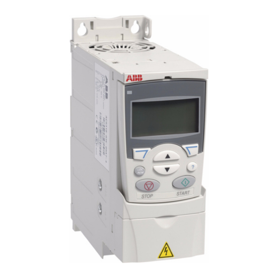
24 Operation principle and hardware description Product overview Layout The layout of the drive is presented below. The figure shows a frame size R2 drive. The construction of the different frame sizes R0…R4 varies to some extent. Covers on (R2) Covers off (R2) Cooling outlet through top cover EMC filter grounding screw (EMC). -
Page 24: Power Connections And Control Interfaces
Operation principle and hardware description 25 Power connections and control interfaces The diagram gives an overview of connections. I/O connections are parameterable. See chapter on page for I/O connections for the different Application macros macros and chapter on page for installation in general. Electrical installation Control panel (RJ-45) -
Page 25: Type Designation Label
A, B, C, … for product revision number XXXX: Integer starting every week from 0001 5 ABB MRP code of the drive 6 CE marking and C-Tick, C-UL US and RoHS marks (the label of your drive shows the valid markings) -
Page 26: Type Designation Key
1) The ACS310 is compatible with ACS-CP-C Basic Control Panel Rev M or later. 2) The ACS310 is compatible with ACS-CP-A Assistant Control Panel Rev E or later (new panel series manufactured since 2007 with serial number XYYWWRXXXX, where year YY = 07 or greater and revision R = E, F, G, …) - Page 27 28 Operation principle and hardware description Phone: 800.894.0412 - Fax: 888.723.4773 - Web: www.clrwtr.com - Email: info@clrwtr.com...
-
Page 28: Mechanical Installation
Mechanical installation 29 Mechanical installation What this chapter contains The chapter tells how to check the installation site, unpack, check the delivery and install the drive mechanically. Checking the installation site The drive may be installed on the wall or in a cabinet. Check the enclosure requirements for the need to use the NEMA 1 option in wall installations (see chapter on page 307. -
Page 29: Required Tools
30 Mechanical installation Floor The floor/material below the installation should be non-flammable. Free space around the drive The required free space for cooling above and below the drive is 75 mm (3 in). No free space is required on the sides of the drive, so drives can be installed side by side. -
Page 30: Unpacking
Mechanical installation 31 Unpacking The drive (1) is delivered in a package that also contains the following items (frame size R2 shown in the figure): • plastic bag (2) including clamping plate (also used for I/O cables in frame sizes R3 and R4), I/O clamping plate (for frame sizes R0…R2), clamps and screws •... -
Page 31: Installing
32 Mechanical installation Installing The instructions in this manual cover drives with the IP20 degree of protection. To comply with NEMA 1, use the MUL-R1, MUL-R3 or MUL-R4 option kit, which is delivered with multilingual installation instructions (3AFE68642868, 3AFE68643147 or 3AUA0000025916, respectively). Install the drive Install the drive with screws or on a DIN rail as appropriate. - Page 32 Mechanical installation 33 3. Position the drive onto the screws on the wall. 4. Tighten the screws in the wall securely. On DIN rail 1. Click the drive to the rail. To detach the drive, press the release lever on top of the drive (1b). Phone: 800.894.0412 - Fax: 888.723.4773 - Web: www.clrwtr.com - Email: info@clrwtr.com...
-
Page 33: Fasten Clamping Plates
34 Mechanical installation Fasten clamping plates 1. Fasten the clamping plate to the plate at the bottom of the drive with the provided screws. 2. For frame sizes R0…R2, fasten the I/O clamping plate to the clamping plate with the provided screws. Phone: 800.894.0412 - Fax: 888.723.4773 - Web: www.clrwtr.com - Email: info@clrwtr.com... -
Page 34: Planning The Electrical Installation
Note: The installation must always be designed and made according to applicable local laws and regulations. ABB does not assume any liability whatsoever for any installation which breaches the local laws and/or other regulations. Furthermore, if the recommendations given by ABB are not followed, the drive may experience problems that the warranty does not cover. -
Page 35: European Union
36 Planning the electrical installation European union To meet the European Union Directives, according to standard EN 60204-1, Safety of Machinery, the disconnecting device must be one of the following types: • a switch-disconnector of utilization category AC-23B (EN 60947-3) •... -
Page 36: Alternative Power Cable Types
Planning the electrical installation 37 Alternative power cable types Power cable types that can be used with the drive are presented below. Note: A separate PE conductor is required Motor cables if the conductivity of the cable shield is not (recommended for input cables also) sufficient for the purpose. -
Page 37: Additional Us Requirements
38 Planning the electrical installation Additional US requirements Type MC continuous corrugated aluminium armor cable with symmetrical grounds or shielded power cable is recommended for the motor cables if metallic conduit is not used. The power cables must be rated for 75 °C (167 °F). Conduit Where conduits must be coupled together, bridge the joint with a ground conductor bonded to the conduit on each side of the joint. -
Page 38: Relay Cable
Control panel cable In remote use, the cable connecting the control panel to the drive must not exceed 3 m (10 ft). The cable type tested and approved by ABB is used in control panel option kits. Routing the cables Route the motor cable away from other cable routes. -
Page 39: Control Cable Ducts
40 Planning the electrical installation A diagram of the cable routing is shown below. Motor cable min. 300 mm (12 in) Drive Power cable Motor cable Input power cable 90° min. 200 mm (8 in) min. 500 mm (20 in) Control cables Control cable ducts 24 V... -
Page 40: Protecting The Drive, Input Power Cable, Motor And Motor Cable In Short Circuit Situations And Against Thermal Overload
Circuit breakers which have been tested by ABB with the ACS350 can be used. Fuses must be used with other circuit breakers. Contact your local ABB representative for the approved breaker types and supply network characteristics. -
Page 41: Protecting The Drive, Motor Cable And Input Power Cable Against Thermal Overload
Motor temperature measurement through the standard I/O Using residual current devices (RCD) with the drive ACS310-03x drives are suitable to be used with residual current devices of Type B. Other measures for protection in case of direct or indirect contact, such as separation from the environment by double or reinforced insulation or isolation from the supply system by a transformer, can also be applied. -
Page 42: Protecting The Contacts Of Relay Outputs
Planning the electrical installation 43 Protecting the contacts of relay outputs Inductive loads (relays, contactors, motors) cause voltage transients when switched off. Equip inductive loads with noise attenuating circuits (varistors, RC filters [AC] or diodes [DC]) in order to minimize the EMC emission at switch-off. If not suppressed, the disturbances may connect capacitively or inductively to other conductors in the control cable and form a risk of malfunction in other parts of the system. - Page 43 44 Planning the electrical installation Phone: 800.894.0412 - Fax: 888.723.4773 - Web: www.clrwtr.com - Email: info@clrwtr.com...
-
Page 44: Electrical Installation
Electrical installation 45 Electrical installation What this chapter contains The chapter tells how to check the insulation of the assembly and the compatibility with IT (ungrounded) and corner grounded TN systems as well as connect power cables, control cables and embedded fieldbus. WARNING! The work described in this chapter may only be carried out by a qualified electrician. -
Page 45: Motor And Motor Cable
1. If you have an IT (ungrounded) or corner grounded TN system, disconnect the internal EMC filter by removing the EMC screw. For 3-phase U-type drives (with type designation ACS310-03U-), the EMC screw is already removed at the factory and replaced by a plastic one. -
Page 46: Connecting The Power Cables
Electrical installation 47 Connecting the power cables Connection diagram Drive INPUT OUTPUT U1 V1 W1 U2 V2 W2 For alternatives, see section Selecting the supply disconnecting device (disconnecting means) page 35. Motor Ground the other end of the PE conductor at the distribution board. Use a separate grounding cable if the conductivity of the cable shield is insufficient (smaller than the conductivity of the phase conductor) and there is no symmetrically constructed grounding conductor in the cable. -
Page 47: Connection Procedure
48 Electrical installation Connection procedure 1. Fasten the grounding conductor (PE) of the input power cable under the grounding clamp. Connect the phase conductors to the U1, V1 and W1 terminals. Use a tightening torque of 0.8 N·m (7 lbf·in) for frame sizes R0…R2, 1.7 N·m (15 lbf·in) for R3, and 2.5 N·m (22 lbf·in) for R4. -
Page 48: Connecting The Control Cables
Electrical installation 49 Connecting the control cables I/O terminals The figure below shows the I/O terminals. Tightening torque is 0.4 N·m / 3.5 lbf·in. X1A: X1B: J701 1: SCR 17: ROCOM 2: AI1 18: RONC 3: GND 19: RONO 4: +10 V 20: DOSRC 5: AI2 21: DOOUT... - Page 49 50 Electrical installation Voltage and current connection for analog inputs Bipolar voltage (-10…10 V) and current (-20…20 mA) are also possible. If a bipolar connection is used instead of a unipolar one, see section Programmable analog on page for how to set parameters accordingly. inputs Unipolar voltage Bipolar voltage...
- Page 50 Electrical installation 51 Connection example of a two-wire sensor Hand/Auto, PID Control, PFC Control and SPFC Control macros (see section on page 99) use analog input 2 (AI2). The macro wiring diagrams Application macros for these macros show the connection when a separately powered sensor is used. The figure below gives an example of a connection using a two-wire sensor.
-
Page 51: Default I/O Connection Diagram
Default values with different macros other macros, see chapter on page 99. Application macros The default I/O connections for the ABB standard macro are given in the figure below. Signal cable shield (screen) Output frequency reference: 0…10 V 1…10 kohm... -
Page 52: Connection Procedure
Electrical installation 53 Connection procedure 1. Remove the terminal cover by simultaneously pushing the recess and sliding the cover off the frame. 2. Digital signals: Strip the outer insulation of the digital signal cable 360 degrees and ground the bare shield under the clamp. 3. -
Page 53: Connecting The Embedded Fieldbus
54 Electrical installation Connecting the embedded fieldbus Embedded fieldbus can be connected to the drive with RS-485 or RS-232. Connection diagram RS-485 The figure below shows the fieldbus connection. J701 GND_A 23 SCR Fieldbus cable shield (screen) 24 B Positive 25 A Negative 25 GND_A Fieldbus common... -
Page 54: Installation Checklist
Installation checklist 55 Installation checklist Checking the installation Check the mechanical and electrical installation of the drive before start-up. Go through the checklist below together with another person. Read chapter Safety page of this manual before you work on the drive. Check MECHANICAL INSTALLATION The ambient operating conditions are allowed. - Page 55 56 Installation checklist Check The motor cable, input power cable and control cables are routed separately. The external control (I/O) connections are OK. The input power voltage cannot be applied to the output of the drive (with a bypass connection). Terminal cover and, for NEMA 1, hood and connection box, are in place.
-
Page 56: Start-Up And Control With I/O
Start-up and control with I/O 57 Start-up and control with I/O What this chapter contains The chapter tells how to: • perform the start-up • start, stop, change the direction of the motor rotation and adjust the speed of the motor through the I/O interface Using the control panel to do these tasks is explained briefly in this chapter. -
Page 57: How To Start Up The Drive Without A Control Panel
58 Start-up and control with I/O • Check the installation. See the checklist in chapter on page Installation checklist How you start up the drive depends on the control panel you have, if any. • If you have no control panel, follow the instructions given in section How to start on page 58. -
Page 58: How To Perform A Manual Start-Up
Enter the motor data from the motor nameplate: Note: Set the motor data to exactly the same value as on the motor nameplate. For ABB Motors example, if the motor nominal speed is 1440 rpm on the motor M2AA 200 MLA 4... - Page 59 • motor nominal power (parameter 9909) 9909 Select the application macro (parameter 9902) 9902 according to how the control cables are connected. The default value 1 (ABB STANDARD) is suitable in most cases. Phone: 800.894.0412 - Fax: 888.723.4773 - Web: www.clrwtr.com - Email: info@clrwtr.com...
- Page 60 Start-up and control with I/O 61 DIRECTION OF THE MOTOR ROTATION Check the direction of the motor rotation. • If the drive is in remote control (REM shown on the left), switch to local control by pressing • To go to the Main menu, press if the bottom line shows OUTPUT;...
-
Page 61: How To Perform A Guided Start-Up
62 Start-up and control with I/O How to perform a guided start-up To be able to perform the guided start-up, you need the Assistant Control Panel. Before you start, ensure that you have the motor nameplate data on hand. POWER-UP Apply input power. - Page 62 Start-up and control with I/O 63 Select the application macro according to which the PAR EDIT control cables are connected. 9902 APPLIC MACRO ABB STANDARD EXIT 00:00 SAVE Continue with the application set-up. After CHOICE completing a set-up task, the Start-up Assistant...
- Page 63 64 Start-up and control with I/O FINAL CHECK After the whole set-up is completed, check that there are no faults or alarms shown on the display and the panel LED is green and does not blink. The drive is now ready for use. Phone: 800.894.0412 - Fax: 888.723.4773 - Web: www.clrwtr.com - Email: info@clrwtr.com...
-
Page 64: How To Control The Drive Through The I/O Interface
Default I/O on page connection diagram according to the connection diagram given for the ABB Standard macro. Ensure that the drive is in remote control. Press key In remote control, the panel display shows text REM. to switch between remote and local control. - Page 65 66 Start-up and control with I/O Phone: 800.894.0412 - Fax: 888.723.4773 - Web: www.clrwtr.com - Email: info@clrwtr.com...
-
Page 66: Control Panels
About control panels Use a control panel to control the ACS310, read status data, and adjust parameters. The drive works with either of two different control panel types: •... -
Page 67: Basic Control Panel
68 Control panels Basic Control Panel Features The Basic Control Panel features: • numeric control panel with an LCD display • copy function – parameters can be copied to the control panel memory for later transfer to other drives or for backup of a particular system. Phone: 800.894.0412 - Fax: 888.723.4773 - Web: www.clrwtr.com - Email: info@clrwtr.com... -
Page 68: Overview
Control panels 69 Overview The following table summarizes the key functions and displays on the Basic Control Panel. No. Use LCD display – Divided into five areas: a. Upper left – Control location: LOC: drive control is local, that is, from the control panel REM: drive control is remote, such as the drive OUTPUT... -
Page 69: Operation
70 Control panels Operation You operate the control panel with the help of menus and keys. You select an option, eg operation mode or parameter, by scrolling the arrow keys until the option is visible in the display and then pressing the key. - Page 70 Control panels 71 How to start, stop and switch between local and remote control You can start, stop and switch between local and remote control in any mode. To be able to start or stop the drive, the drive must be in local control. Step Action Display •...
-
Page 71: Output Mode
72 Control panels Output mode In the Output mode, you can: • monitor actual values of up to three group signals, one 01 OPERATING DATA signal at a time • start, stop, change the direction and switch between local and remote control. You get to the Output mode by pressing until the display shows text OUTPUT at the bottom. -
Page 72: Reference Mode
Control panels 73 Reference mode In the Reference mode, you can: • set the frequency reference • start, stop, change the direction and switch between local and remote control. How to set the frequency reference Step Action Display Go to the Main menu by pressing if you are in the Output mode, otherwise by pressing repeatedly until you see MENU at the bottom. -
Page 73: Parameter Mode
74 Control panels Parameter mode In the Parameter mode, you can: • view and change parameter values • select and modify the signals shown in the Output mode • start, stop, change the direction and switch between local and remote control. How to select a parameter and change its value Step Action Display... - Page 74 Control panels 75 How to select the monitored signals Step Action Display You can select which signals are monitored in the Output mode and how they are displayed with group parameters. See page 34 PANEL DISPLAY detailed instructions on changing parameter values. By default, the display shows three signals: Signal 1: OUTPUT FREQ...
-
Page 75: Copy Mode
76 Control panels Copy mode The Basic Control Panel can store a full set of drive parameters and up to two user sets of drive parameters to the control panel. The control panel memory is non- volatile. In the Copy mode, you can do the following: •... -
Page 76: Basic Control Panel Alarm Codes
Control panels 77 How to upload and download parameters For the upload and download functions available, see above. Step Action Display Go to the Main menu by pressing if you are in the Output mode, otherwise by pressing repeatedly until you see MENU at the bottom. MENU If the panel is not in the Copy mode (“CoPY”... -
Page 77: Assistant Control Panel
78 Control panels Assistant Control Panel Features The Assistant Control Panel features: • alphanumeric control panel with an LCD display • language selection for the display • Start-up Assistant to ease drive commissioning • copy function – parameters can be copied to the control panel memory for later transfer to other drives or for backup of a particular system. -
Page 78: Overview
Control panels 79 Overview The following table summarizes the key functions and displays on the Assistant Control Panel No. Use Status LED – Green for normal operation. If LED is flashing, or red, see section on page 306. LEDs 49.1Hz 49 1 Hz LCD display –... -
Page 79: Operation
80 Control panels Status line The top line of the LCD display shows the basic status information of the drive. 49.1Hz MAIN MENU No. Field Alternatives Significance Control location Drive control is local, that is, from the control panel. Drive control is remote, such as the drive I/O or fieldbus. - Page 80 Control panels 81 Initially, the panel is in the Output mode, where you can 49.1Hz start, stop, change the direction, switch between local and 49 1 Hz 0 5 A remote control, modify the reference value and monitor up 10 7 % to three actual values.
- Page 81 82 Control panels How to get help Step Action Display Press to read the context-sensitive help text for the PAR GROUPS item that is highlighted. 01 OPERATING DATA 03 FB ACTUAL SIGNALS 04 FAULT HISTORY 10 START/STOP/DIR 11 REFERENCE SELECT EXIT 00:00 If help text exists for the item, it is shown on the display.
- Page 82 Control panels 83 How to start, stop and switch between local and remote control You can start, stop and switch between local and remote control in any mode. To be able to start or stop the drive, the drive must be in local control. Step Action Display •...
-
Page 83: Output Mode
84 Control panels Output mode In the Output mode, you can: • monitor actual values of up to three signals in group 01 OPERATING DATA • change the direction of the motor rotation • set the frequency reference • adjust the display contrast •... - Page 84 Control panels 85 How to set the frequency reference Step Action Display EXIT If you are not in the Output mode, press repeatedly 49.1Hz until you get there. 49 1 Hz 0 5 A 10 7 % 00:00 MENU If the drive is in remote control (REM shown on the st a tus 49.1Hz line), switch to local control by pressing .
-
Page 85: Parameters Mode
EDIT Select the appropriate parameter with keys PARAMETERS . The current value of the parameter is shown 9901 LANGUAGE 9902 APPLIC MACRO below the selected parameter. ABB STANDARD 9905 MOTOR NOM VOLT 9906 MOTOR NOM CURR 00:00 EXIT EDIT EDIT... - Page 86 Control panels 87 Step Action Display SAVE • To save the new value, press PARAMETERS 9901 LANGUAGE • To cancel the new value and keep the original, press 9902 APPLIC MACRO CANCEL 3-WIRE 9905 MOTOR NOM VOLT 9906 MOTOR NOM CURR EXIT 00:00 EDIT...
-
Page 87: Assistants Mode
88 Control panels Step Action Display Select the scalings for the signals by specifying the PAR EDIT minimum and maximum display values. This has no 3406 OUTPUT1 MIN effect if parameter is set to 9 (DIRECT). 3404/3411/3418 0.0 Hz For details, see parameters and 3407. - Page 88 Control panels 89 Assistants mode When the drive is first powered up, the Start-up Assistant guides you through the setup of the basic parameters. The Start-up Assistant is divided into assistants, each of which is responsible for the specification of a related parameter set, for example Motor Set-up or PID Control.
-
Page 89: Changed Parameters Mode
90 Control panels Step Action Display • To specify a new value, press keys PAR EDIT 9905 MOTOR NOM VOLT 240 V EXIT 00:00 SAVE • To ask for information on the requested parameter, HELP press key . Scroll the help text with keys Set as given on the EXIT motor nameplate. -
Page 90: Fault Logger Mode
Control panels 91 Changed Parameters mode In the Changed Parameters mode, you can: • view a list of all parameters that have been changed from the macro default values • change these parameters • start, stop, change the direction and switch between local and remote control. How to view and edit changed parameters Step Action... -
Page 91: Time And Date Mode
92 Control panels Fault Logger mode In the Fault Logger mode, you can: • view the drive fault history of maximum ten faults (after a power off, only the three latest faults are kept in the memory) • see the details of the three latest faults (after a power off, the details of only the most recent fault is kept in the memory) •... - Page 92 Control panels 93 Time and Date mode In the Time and Date mode, you can: • show or hide the clock • change date and time display formats • set the date and time • enable or disable automatic clock transitions according to the daylight saving changes •...
-
Page 93: Parameter Backup Mode
94 Control panels Step Action Display • To set the time, select SET TIME on the menu and SET TIME press . Specify the hours with keys , and press .Then specify the minutes. Press 15:41 CANCEL to save or to cancel your changes. - Page 94 Control panels 95 Parameter Backup mode The Parameter Backup mode is used to export parameters from one drive to another or to make a backup of the drive parameters. Uploading to the panel stores all drive parameters, including up to two user sets, to the Assistant Control Panel. The full set, partial parameter set (application) and user sets can then be downloaded from the control panel to another drive or the same drive.
- Page 95 96 Control panels How to upload and download parameters For the upload and download functions available, see above. Step Action Display MENU Go to the Main menu by pressing if you are in the MAIN MENU EXIT Output mode, otherwise by pressing repeatedly until PARAMETERS you get to the Main menu.
-
Page 96: I/O Settings Mode
Select BACKUP INFO on the Par Backup menu with BACKUP INFO keys , and press . The display DRIVE TYPE ACS310 shows the following information about the drive where 3304 DRIVE RATING the backup was made: 9A74i 3301 FIRMWARE DRIVE TYPE:... - Page 97 98 Control panels I/O Settings mode In the I/O Settings mode, you can: • check the parameter settings related to any I/O terminal • edit the parameter setting. For example, if “1103: REF1” is listed under Ain1 (Analog input 1), that is, parameter REF1 SELECT has value AI1, you can 1103 change its value to eg AI2.
-
Page 98: Application Macros
APPLIC MACRO, makes the essential changes and 9902 saves the result as a user macro. The ACS310 has eight standard macros and two user macros. The table below contains a summary of the macros and describes suitable applications. Macro Suitable applications... - Page 99 100 Application macros Macro Suitable applications PID Control Process control applications, for example different closed loop control systems such as pressure control, level control and flow control. It is possible to switch between process and speed control: Some control signal terminals are reserved for process control, others for speed control. One digital input selects between process and speed control.
-
Page 100: Summary Of The I/O Connections Of The Application Macros
Application macros 101 Summary of the I/O connections of the application macros The following table gives the summary of the default I/O connections of all application macros. Input/ Macro output 3-wire Alternate Motor Hand/Auto PID Standard Potentiom. Control Control SPFC Control Freq. -
Page 101: Abb Standard Macro
102 Application macros ABB Standard macro This is the default macro. It provides a general purpose I/O configuration with three constant speeds. Parameter values are the default values given in section on page 161. parameters If you use other than the default connections presented below, see section on page 49. -
Page 102: 3-Wire Macro
Application macros 103 3-wire macro This macro is used when the drive is controlled using momentary push-buttons. It provides three constant speeds. To enable the macro, set the value of parameter APPLIC MACRO to 2 (3-WIRE). 9902 For the parameter default values, see section Default values with different macros page 151. -
Page 103: Alternate Macro
104 Application macros Alternate macro This macro provides an I/O configuration adapted to a sequence of DI control signals used when alternating the rotation direction of the motor. To enable the macro, set the value of parameter APPLIC MACRO to 3 (ALTERNATE). 9902 For the parameter default values, see section Default values with different macros... -
Page 104: Motor Potentiometer Macro
Application macros 105 Motor Potentiometer macro This macro provides a cost-effective interface for PLCs that vary the speed of the motor using only digital signals. To enable the macro, set the value of parameter 9902 APPLIC MACRO to 4 (MOTOR POT). For the parameter default values, see section Default values with different macros page 151. -
Page 105: Hand/Auto Macro
106 Application macros Hand/Auto macro This macro can be used when switching between two external control devices is needed. To enable the macro, set the value of parameter APPLIC MACRO to 9902 5 (HAND/AUTO). For the parameter default values, see section Default values with different macros page 151. -
Page 106: Pid Control Macro
Application macros 107 PID Control macro This macro provides parameter settings for closed-loop control systems such as pressure control, flow control, etc. Control can also be switched to speed control using a digital input. To enable the macro, set the value of parameter APPLIC 9902 MACRO to 6 (PID CONTROL). -
Page 107: Pfc Control Macro
108 Application macros PFC Control macro This macro provides parameter settings for pump and fan control (PFC) applications. To enable the macro, set the value of parameter APPLIC MACRO to 7 (PFC 9902 CONTROL). For the parameter default values, see section Default values with different macros page 151. -
Page 108: Spfc Control Macro
Application macros 109 SPFC Control macro This macro provides parameter settings for pump and fan control (SPFC) applications with a soft start function. To enable the macro, set the value of parameter 9902 APPLIC MACRO to 15 (SPFC CONTROL). For the parameter default values, see section Default values with different macros page 151. -
Page 109: User Macros
110 Application macros User macros In addition to the standard application macros, it is possible to create two user macros. The user macro allows the user to save the parameter settings, including group DATA, into the permanent memory and recall the data at a later 99 START-UP time. -
Page 110: Program Features
Program features 111 Program features What this chapter contains The chapter describes program features. For each feature, there is a list of related user settings, actual signals, and fault and alarm messages. Start-up Assistant Introduction The Start-up Assistant (requires the Assistant Control Panel) guides the user through the start-up procedure, helping to enter the requested data (parameter values) to the drive. -
Page 111: Default Order Of The Tasks
MACRO), the Start-up Assistant decides which consequent tasks it suggests. The default tasks are shown in the table below. Application selection Default tasks ABB STANDARD Language Select, Motor Set-up, Application, Option Modules, Speed Control EXT1, Speed Control EXT2, Start/Stop Control, Timed Functions, Protections, Output Signals... -
Page 112: List Of The Tasks And The Relevant Drive Parameters
Program features 113 List of the tasks and the relevant drive parameters Depending on the selection made in the Application task (parameter APPLIC 9902 MACRO), the Start-up Assistant decides which consequent tasks it suggests. Name Description Set parameters Selecting the language Language Select 9901 Setting the motor data... - Page 113 114 Program features Name Description Set parameters Setting the timed functions Timed Functions 36 TIMED FUNCTIONS Selecting the timed start/stop control for 1001, 1002 external control locations EXT1 and EXT2 Selecting timed EXT1/EXT2 control 1102 Activation of timed constant speed 1 1201 Selecting timed function status indicated 1401...
-
Page 114: Contents Of The Assistant Displays
Program features 115 Contents of the assistant displays There are two types of displays in the Start-up Assistant: Main displays and the information displays. The main displays prompt the user to feed in information. The assistant steps through the main displays. The information displays contain help texts for the main displays. -
Page 115: Local Control
116 Program features Local control The control commands are given from the control panel keypad when the drive is in local control. LOC indicates local control on the panel display. Assistant panel Basic panel 49.1Hz 49 1 Hz 0 5 A 10 7 % OUTPUT 00:00... -
Page 116: Diagnostics
Program features 117 Diagnostics Actual signals Additional information EXT1/EXT2 reference 0111/0112 Block diagram: Start, stop, direction source for EXT1 The figure below shows the parameters that select the interface for start, stop, and direction for external control location EXT1. Select EXT1 Start/stop/ direction... -
Page 117: Reference Types And Processing
118 Program features Reference types and processing The drive can accept a variety of references in addition to the conventional analog input and control panel signals. • The drive reference can be given with two digital inputs: One digital input increases the speed, the other decreases it. -
Page 118: Reference Trimming
Program features 119 Reference trimming In reference trimming, the external reference is corrected depending on the measured value of a secondary application variable. The block diagram below illustrates the function. Switch Select 1105 REF1 MAX / DIRECT (2) 1108 REF 2 MAX REF1 (Hz/rpm) / max. -
Page 119: Example
120 Program features Example The drive runs a conveyor line. It is speed controlled but the line tension also needs to be taken into account: If the measured tension exceeds the tension setpoint, the speed will be slightly decreased, and vice versa. To accomplish the desired speed correction, the user •... -
Page 120: Diagnostics
Program features 121 Diagnostics Actual signal Additional information Analog input values 0120, 0121 AI1/A2 signal loss 1401 Alarm AI1/AI2 signal below AI1/AI2 FAULT LIMIT AI1 LOSS AI2 LOSS (3021/3022) Fault AI1/AI2 signal below limit AI1/AI2 FAULT LIMIT AI1 LOSS AI2 LOSS (3021/3022) Incorrect AI signal scaling (1302... -
Page 121: Programmable Digital Inputs
122 Program features Programmable digital inputs The drive has five programmable digital inputs. The update time for the digital inputs is 2 ms. It is possible to delay the state change of digital inputs with delays defined in group . This enables very simple program sequences by connecting 18 FREQ IN &... -
Page 122: Diagnostics
Program features 123 Diagnostics Actual signal Additional information DI status 0160 DI status at the time the latest fault occurred 0414 Programmable relay output The drive has one programmable relay output. It is possible to add three additional relay outputs with the optional Relay Output Extension Module MREL-0. For more information, see MREL-01 Relay Output Extension Module User's Manual (3AUA0000035974 [English]). -
Page 123: Diagnostics
124 Program features Diagnostics Actual signal Additional information Frequency input value 0161 Transistor output The drive has one programmable transistor output. The output can be used either as digital output or frequency output (0…16000 Hz). The update time for the transistor/frequency output is 2 ms. -
Page 124: Diagnostics
Program features 125 Parameter Additional information Group Selection of an actual signals to be displayed on the 34 PANEL DISPLAY control panel Diagnostics Actual signal Additional information Group … Lists of actual signals 01 OPERATING DATA FAULT HISTORY Power loss ride-through If the incoming supply voltage is cut off, the drive will continue to operate by utilizing the kinetic energy of the rotating motor. -
Page 125: Dc Magnetizing
126 Program features DC Magnetizing When DC Magnetizing is activated, the drive automatically magnetizes the motor before starting. This feature guarantees the highest possible breakaway torque, up to 180% of the motor nominal torque. By adjusting the paramagnetism time, it is possible to synchronize the motor start. -
Page 126: Critical Speeds
Program features 127 Critical Speeds A Critical Speeds function is available for applications where it is necessary to avoid certain motor speeds (drive output frequencies) or speed bands (output frequency bands) because of eg mechanical resonance problems. The user can define three critical frequencies or frequency bands. -
Page 127: Custom U/F Ratio
128 Program features Custom U/f ratio The user can define a U/f curve (output voltage as a function of frequency). This custom ratio is used only in special applications where linear and squared U/f ratio are not sufficient (eg when motor break-away torque needs to be boosted). Voltage (V) Custom U/f ratio par. -
Page 128: Ir Compensation
Program features 129 IR compensation When IR compensation is activated, the drive Motor voltage gives an extra voltage boost to the motor at low speeds. IR compensation is useful in IR compensation applications that require high breakaway torque. Settings No compensation Parameter IR COMP VOLT 2603... -
Page 129: Motor Thermal Protection
130 Program features Motor Thermal Protection The motor can be protected against overheating by activating the Motor Thermal Protection function. The drive calculates the temperature of the motor on the basis of the following assumptions: 1. The motor is in the ambient temperature of 30 °C when power is applied to the drive. -
Page 130: Preprogrammed Faults
Program features 131 Settings Parameter WIRING FAULT 3023 Preprogrammed faults Overcurrent The overcurrent trip limit for the drive is 325% of the drive nominal current. DC overvoltage The DC overvoltage trip limit is 420 V (for 200 V drives) and 840 V (for 400 V drives). DC undervoltage The DC undervoltage trip limit is adaptive. -
Page 131: Automatic Resets
132 Program features Power limit Power limitation is used to protect the input bridge and the DC intermediate circuit. If the maximum allowed power is exceeded, the drive torque is automatically limited. Maximum overload and continuous power limits depend on the drive hardware. For specific values, see chapter on page 307. -
Page 132: Pid Control
Program features 133 Parameter lock The user can prevent parameter adjustment by activating the parameter lock. Settings Parameters PARAMETER LOCK and PASS CODE 1602 1603 PID control There are two built-in PID controllers in the drive: • Process PID (PID1) and •... -
Page 133: Block Diagrams
134 Program features Block diagrams The figure below shows an application example: The controller adjusts the speed of a pressure boost pump according to the measured pressure and the set pressure reference. Example: PID control block diagram Pressure boost pump %ref A C S 6 0 0 Drive... - Page 134 Program features 135 The following figure presents the speed/scalar control block diagram for process controller PID1. Phone: 800.894.0412 - Fax: 888.723.4773 - Web: www.clrwtr.com - Email: info@clrwtr.com...
-
Page 135: Settings
136 Program features Settings Parameter Additional information Local control mode reference type selection 1101 EXT1/2 selection 1102 PID1 activation 1106 REF2 minimum limit 1107 PID2 output (external controller) connection to AO 1501 PID control macro selection 9902 Group PID1 settings 40 PROCESS PID SET 1…41 PROCESS PID SET 2 Group... -
Page 136: Sleep Function For The Process Pid (Pid1) Control
Program features 137 Sleep function for the process PID (PID1) control The sleep function operates on a 2 ms time level. The block diagram below illustrates the sleep function enable/disable logic. The sleep function can be put into use only when the PID control is active. Compare Select NOT SEL... -
Page 137: Example
138 Program features Example The time scheme below visualizes the operation of the sleep function. Reference Sleep boost time (4030) Sleep boost step (4031) Time Wake-up delay Selected process (4026) actual value Wake-up level deviation (4025) Time Output frequency Control panel: = Sleep delay (4024) SLEEP t <... -
Page 138: Diagnostics
Program features 139 Settings Parameter Additional information PID control activation 9902 Sleep function settings 4022…4026, 4030, 4031, 4122…4126, 4130, 4131 Diagnostics Parameter Additional information PID sleep function status through RO 1 1401 PID sleep function status through RO 2…4. With option 1402/1403/1410 MREL-01 only. -
Page 139: Settings
140 Program features It is also possible to monitor motor temperature by connecting a PTC sensor and a thermistor relay between the +24 V DC voltage supply offered by the drive and a digital input. The figure below displays the connection. Par. -
Page 140: Timed Functions
Program features 141 Timed functions A variety of drive functions can be time controlled, eg start/stop and EXT1/EXT2 control. The drive offers • four start and stop times (START TIME 1…4, STOP TIME 1…4) • four start and stop days (START DAY 1…4, STOP DAY 1…4) •... -
Page 141: Example
142 Program features A parameter which is triggered by a timed function can be connected to only one timed function at a time. 1001 EXT 1 COMMANDS TIMED FUNC 1 1002 EXT 2 COMMANDS 3626 TIMED FUNC 1 SRC 1102 EXT1/EXT2 SE 1201 CONST SPEED SEL TIMED FUNC 2 1209 TIME MODE SEL... -
Page 142: User Load Curve
Program features 143 User load curve The user can specify a load curve (motor torque as a function of frequency) for supervision. The curve is defined by five points. Supervision can be set for the torque dropping below the underload curve, exceeding the overload curve, or both. A fault is generated if the torque has been out of the allowed area for longer than the user-defined time limit. -
Page 143: Energy Optimizer
144 Program features Energy optimizer Energy optimizer optimizes the flux so that the total energy consumption and motor noise level are reduced when the drive operates below the nominal load. The total efficiency (motor and drive) can be improved by 1…10% depending on load torque and speed. -
Page 144: Settings
Program features 145 Settings Parameter group 46 PUMP CLEANING Load analyzer The load analyzer can be used for analyzing the customer’s process and sizing the drive and the motor. The peak value is logged at 2 ms level, and the distribution loggers are updated on 0.2 s (200 ms) time level. -
Page 145: Pfc And Spfc Control
146 Program features PFC and SPFC control PFC control Pump and Fan Control (PFC) control switches auxiliary pumps on and off as required by capacity changes. Autochange function alternates between pumps to keep the duty times of the pumps equal. Interlocks function enables the drive to detect if any of the pumps are unavailable (eg switched off for maintenance), in which case the next available pump is started instead. -
Page 146: Settings
Program features 147 When the speed regulated motor reaches the full output, it is disconnected from the drive and switched to direct on-line connection, with a slight delay in between. Auxiliary motor 2 is connected to drive output. After a slight delay the motor speed is increased to fulfil the pumping capacity needed. - Page 147 148 Program features Phone: 800.894.0412 - Fax: 888.723.4773 - Web: www.clrwtr.com - Email: info@clrwtr.com...
-
Page 148: Actual Signals And Parameters
Actual signals and parameters 149 Actual signals and parameters What this chapter contains The chapter describes the actual signals and parameters and gives the fieldbus equivalent values for each signal/parameter. It also contains a table of the default values for the different macros. Note: When the control panel is in the short parameter view, ie when parameter 1611 PARAMETER VIEW is set to 2 (SHORT VIEW), the control panel only shows a... -
Page 149: Fieldbus Equivalent
150 Actual signals and parameters Fieldbus equivalent Example: If MAXIMUM FREQ (see page 183) is set from an external control 2008 system, an integer value of 1 corresponds to 0.1 Hz. All the read and sent values are limited to 16 bits (-32768…32767). Phone: 800.894.0412 - Fax: 888.723.4773 - Web: www.clrwtr.com - Email: info@clrwtr.com... -
Page 150: Default Values With Different Macros
3-WIRE ALTERNA MOTOR HAND/ SPFC Selection STANDARD AUTO CONTROL CONTROL CONTROL APPLIC 1 = ABB 2 = 3-WIRE 3 = ALTER 4 = MOTOR 6 = PID 7 = PFC 15 = SPFC 9902 MACRO STANDARD NATE HAND/AU CONTROL CONTROL... -
Page 151: Actual Signals In The Short Parameter View
152 Actual signals and parameters Actual signals in the short parameter view Actual signals in the short parameter view Name/Value Description FbEq Fault history (read-only). See group 04 FAULT HISTORY 04 FAULT HISTORY the list of all parameters. 0401 LAST FAULT Code of the latest fault. -
Page 152: Accel/Decel
Actual signals and parameters 153 Parameters in the short parameter view Name/Value Description Default Acceleration and deceleration times. See group 22 ACCEL/DECEL in the list of all parameters. ACCEL/DECEL 2202 ACCELER Defines the acceleration time 1. 5.0 s TIME 1 2203 DECELER Defines the deceleration time 1. -
Page 153: All Actual Signals
154 Actual signals and parameters All actual signals All actual signals Name/Value Description FbEq Basic signals for monitoring the drive (read-only) 01 OPERATING DATA 0101 SPEED & DIR Calculated motor speed in rpm. A negative value indicates 1 = 1 rpm reverse direction. - Page 154 Actual signals and parameters 155 All actual signals Name/Value Description FbEq 0130 PID 1 FBK Feedback signal for the process PID1 controller. Unit depends on parameter UNIT, UNIT SCALE and 4006 4007 PID 1 PARAM SET settings. 4027 0131 PID 2 FBK Feedback signal for the PID2 controller.
-
Page 155: Fb Actual Signals
156 Actual signals and parameters All actual signals Name/Value Description FbEq 0162 RO STATUS Status of relay output 1. 1 = RO is energized, 0 = RO is de- 1 = 1 energized. 0163 TO STATUS Status of transistor output, when transistor output is used as 1 = 1 a digital output. - Page 156 Actual signals and parameters 157 All actual signals Name/Value Description FbEq 0303 FB STS WORD A 16-bit data word. See section DCU communication profile on page 283. 0304 FB STS WORD A 16-bit data word. See section DCU communication profile on page 0305 FAULT WORD A 16-bit data word.
- Page 157 158 Actual signals and parameters All actual signals Name/Value Description FbEq 0307 FAULT WORD A 16-bit data word. For the possible causes and remedies and fieldbus equivalents, see chapter on page Fault tracing 287. Bit 0 = EFB 1 Bit 1 = EFB 2 Bit 2 = EFB 3 Bit 3 = INCOMPATIBLE SW Bit 4 = USER LOAD CURVE...
-
Page 158: Fault History
Actual signals and parameters 159 All actual signals Name/Value Description FbEq Bit 2 = Reserved Bit 3 = Reserved Bit 4 = START ENABLE 1 MISSING Bit 5 = START ENABLE 2 MISSING Bit 6 = EMERGENCY STOP Bit 7 = Reserved Bit 8 = FIRST START Bit 9 = Reserved Bit 10 = USER LOAD CURVE... - Page 159 160 Actual signals and parameters All actual signals Name/Value Description FbEq 0408 TORQUE AT Motor torque in percent of the motor nominal torque at the 1 = 0.1% time the latest fault occurred 0409 STATUS AT Drive status in hexadecimal format at the time the latest fault occurred 0412 PREVIOUS Fault code of the 2nd latest fault.
-
Page 160: All Parameters
Actual signals and parameters 161 All parameters All parameters Name/Value Description Def/FbEq 10 START/STOP/DIR The sources for external start, stop and direction control 1001 EXT1 Defines the connections and the source for the start, stop DI1,2 COMMANDS and direction commands for external control location 1 (EXT1). - Page 161 162 Actual signals and parameters All parameters Name/Value Description Def/FbEq COMM Fieldbus interface as the source for the start and stop commands, ie control word FB CMD WORD 1 bits 0301 0…1. The control word is sent by the fieldbus controller via the fieldbus adapter or embedded fieldbus (Modbus) to the drive.
-
Page 162: Reference Select
1106 SELECT. COMM Fieldbus interface as the source for EXT1/EXT2 selection, ie control word FB CMD WORD 1 bit 5 (with ABB 0301 Drives profile EFB PAR 19 bit 11). The control word is 5319 sent by the fieldbus controller via the fieldbus adapter or embedded fieldbus (Modbus) to the drive. - Page 163 164 Actual signals and parameters All parameters Name/Value Description Def/FbEq AI1/JOYST Analog input AI1 as joystick. The minimum input signal runs the motor at the maximum reference in the reverse direction, the maximum input at the maximum reference in the forward direction. Minimum and maximum references are defined by parameters REF1 MIN and REF1...
- Page 164 Actual signals and parameters 165 All parameters Name/Value Description Def/FbEq DI3U,4D(NC) Digital input 3: Reference increase. Digital input DI4: Reference decrease. The program stores the active speed reference (not reset by a stop command). The reference is not saved if the control source is changed (from EXT1 to EXT2, from EXT2 to EXT1 or from LOC to REM).
- Page 165 166 Actual signals and parameters All parameters Name/Value Description Def/FbEq 1105 REF1 MAX Defines the maximum value for external reference REF1. E: 50.0 Hz Corresponds to the maximum setting of the used source U: 60.0 Hz signal. 0.0…500.0 Hz Maximum value in Hz. See the example for parameter 1 = 0.1 Hz 1104 REF1 MIN.
-
Page 166: Constant Speeds
Actual signals and parameters 167 All parameters Name/Value Description Def/FbEq Constant speed (drive output frequency) selection and 12 CONSTANT values. See section on page 127. SPEEDS Constant speeds 1201 CONST Activates the constant speeds (drive output frequencies) or DI3,4 SPEED SEL selects the activation signal. - Page 167 168 Actual signals and parameters All parameters Name/Value Description Def/FbEq TIMED Speed selection with TIMED FUNC 1 and TIMED FUNC 2. FUN1&2 See parameter TIMED MODE SEL. 1209 DI1(INV) Speed defined by parameter CONST SPEED 1 is 1202 activated through inverted digital input DI1. 0 = active, 1 = inactive.
- Page 168 Actual signals and parameters 169 All parameters Name/Value Description Def/FbEq 1204 CONST Defines constant speed (drive output frequency) 3. E: 15.0 Hz SPEED 3 U: 18.0 Hz 0.0…500.0 Hz Output frequency in Hz 1 = 0.1 Hz 1205 CONST Defines constant speed (drive output frequency) 4. E: 20.0 Hz SPEED 4 U: 24.0 Hz...
-
Page 169: Analog Inputs
170 Actual signals and parameters All parameters Name/Value Description Def/FbEq CS1/2/3/4 Constant speed selection with TIMED FUNC n. 1 = timed function active, 0 = timed function inactive. TIMED Operation FUNC n Speed defined by parameter CONST 1202 SPEED 1 Speed defined by parameter CONST 1203... -
Page 170: Relay Outputs
Actual signals and parameters 171 All parameters Name/Value Description Def/FbEq -100.0…100.0% Value in percent of the full signal range. 1 = 0.1% Example: If the maximum value for analog input is 10 mA, the percent value for 0…20 mA range is: (10 mA / 20 mA) ·... - Page 171 172 Actual signals and parameters All parameters Name/Value Description Def/FbEq STARTED The drive has received start command. Relay is energized even if Run Enable signal is off. Relay is de-energized when drive receives a stop command or a fault occurs. SUPRV1 Status according to supervision parameters 3201…3203.
- Page 172 Actual signals and parameters 173 All parameters Name/Value Description Def/FbEq COMM Fieldbus control signal COMM RO WORD. 0 = de- 0134 energize output, 1 = energize output. 0134 value Binary 000000 000001 000010 000011 COMM(-1) Fieldbus control signal COMM RO WORD. 0 = de- 0134 energize output, 1 = energize output 0134 value...
-
Page 173: Analog Outputs
174 Actual signals and parameters All parameters Name/Value Description Def/FbEq 1403 RELAY See parameter RELAY OUTPUT 1. Available only if NOT SEL 1401 OUTPUT 3 the Relay Output Extension Module MREL-0 is connected to the drive. 1404 RO 1 ON Defines the operation delay for relay output RO 1. -
Page 174: System Controls
Actual signals and parameters 175 All parameters Name/Value Description Def/FbEq 1502 AO1 Defines the minimum value for signal selected with CONTENT MIN parameter AO1 CONTENT SEL. 1501 AO minimum and maximum correspond the MINIMUM 1504 AO1 and MAXIMUM AO1 settings as follows: 1505 AO (mA) AO (mA) - Page 175 Fieldbus interface as the source for inverted Run Enable signal (Run Disable), ie control word FB CMD WORD 0301 1 bit 6 (with ABB drives profile EFB PAR 19 bit 3). The 5319 control word is sent by the fieldbus controller via the embedded fieldbus (Modbus) to the drive.
- Page 176 Description Def/FbEq COMM Fieldbus interface as the source for the fault reset signal, ie control word FB CMD WORD 1 bit 4 (with ABB drives 0301 profile EFB PAR 19 bit 7). The control word is sent by 5319 the fieldbus controller via the embedded fieldbus (Modbus) to the drive.
- Page 177 178 Actual signals and parameters All parameters Name/Value Description Def/FbEq 1606 LOCAL LOCK Disables entering local control mode or selects the source NOT SEL for the local control mode lock signal. When local lock is active, entering the local control mode is disabled (LOC/REM key of the panel).
- Page 178 Actual signals and parameters 179 All parameters Name/Value Description Def/FbEq 1608 START Selects the source for the Start Enable 1 signal. NOT SEL ENABLE 1 Note: Functionality of the Start Enable signal is different from the Run Enable signal. Example: External damper control application using Start Enable and Run Enable.
-
Page 179: Freq In & Tran Out
180 Actual signals and parameters All parameters Name/Value Description Def/FbEq DI2(INV) See selection DI1(INV). DI3(INV) See selection DI1(INV). DI4(INV) See selection DI1(INV). DI5(INV) See selection DI1(INV). 1609 START Selects the source for the Start Enable 2 signal. See NOT SEL ENABLE 2 parameter START ENABLE 1. - Page 180 Actual signals and parameters 181 All parameters Name/Value Description Def/FbEq 1807 DO OFF Defines the release delay for digital output DO. 0.0 s DELAY 0.0…3600.0 s Delay time 1 = 0.1 s 1808 FO CONTENT Selects a drive signal to be connected to frequency output x…x Parameter index in group DATA.
-
Page 181: 20 Limits
182 Actual signals and parameters All parameters Name/Value Description Def/FbEq 1819 DI3 OFF See parameter DI1 OFF DELAY. 0.0 s 1815 DELAY 1820 DI4 ON DELAY See parameter DI1 ON DELAY. 0.0 s 1814 1821 DI4 OFF See parameter DI1 OFF DELAY. 0.0 s 1815 DELAY... -
Page 182: 21 Start/Stop
Actual signals and parameters 183 All parameters Name/Value Description Def/FbEq 2007 MINIMUM Defines the minimum limit for the drive output frequency. 0.0 Hz FREQ A positive (or zero) minimum frequency value defines two ranges, one positive and one negative. A negative minimum frequency value defines one speed range. - Page 183 184 Actual signals and parameters All parameters Name/Value Description Def/FbEq TORQ BOOST Torque boost should be selected if a high break-away torque is required. The drive pre-magnetizes the motor with DC current before the start. The pre-magnetizing time is defined by parameter DC MAGN TIME.
- Page 184 Actual signals and parameters 185 All parameters Name/Value Description Def/FbEq 2108 START INHIBIT Enables the start inhibit function. Drive start is inhibited if: • fault is reset. • Run Enable signal activates while the start command is active. See parameter RUN ENABLE.
-
Page 185: Accel/Decel
186 Actual signals and parameters All parameters Name/Value Description Def/FbEq 2112 ZERO SPEED Defines the delay for the Zero Speed Delay function. The 0.0 s DELAY function is useful in applications where a smooth and quick restarting is essential. During the delay the drive knows accurately the rotor position. - Page 186 If a short deceleration time is needed for a high inertia application, note that the ACS310 cannot be equipped with a brake resistor. Actual deceleration time depends on parameter 2204 RAMP SHAPE 1 setting.
- Page 187 188 Actual signals and parameters All parameters Name/Value Description Def/FbEq 2204 RAMP SHAPE Selects the shape of the acceleration/deceleration ramp 1. LINEAR The function is deactivated during emergency stop. 0.0 = LINEAR 0.0: Linear ramp. Suitable for steady acceleration or 1 = 0.1 s 0.1…1000.0 s deceleration and for slow ramps.
-
Page 188: Critical Speeds
DCU communication on page profile ABB Drives communication profile on page 278. DI1(INV) Inverted digital input DI1. 0 = ramp input is forced to zero. Ramp output will ramp to zero according to the used ramp time. -
Page 189: Motor Control
190 Actual signals and parameters All parameters Name/Value Description Def/FbEq 0.0…500.0 Hz Limit in Hz. The value cannot be below the minimum 1 = 0.1 Hz (parameter CRIT SPEED 1 LO). 2502 2504 CRIT SPEED 2 See parameter CRIT SPEED 1 LO. 0.0 Hz 2502 0.0…500.0 Hz... - Page 190 Actual signals and parameters 191 All parameters Name/Value Description Def/FbEq 2605 U/F RATIO Selects the voltage to frequency (U/f) ratio below the field SQUARE weakening point. LINEAR Linear ratio for constant torque applications. SQUARED Squared ratio for centrifugal pump and fan applications. With squared U/f ratio the noise level is lower for most operating frequencies.
- Page 191 192 Actual signals and parameters All parameters Name/Value Description Def/FbEq 2608 SLIP COMP Defines the slip gain for the motor slip compensation RATIO control. 100% means full slip compensation, 0% means no slip compensation. Other values can be used if a static speed error is detected despite the full slip compensation.
-
Page 192: Maintenance Trig
Actual signals and parameters 193 All parameters Name/Value Description Def/FbEq 2618 FW VOLTAGE Defines the voltage of the U/f curve when frequency is equal 95% of to or exceeds the motor nominal frequency (9907 MOTOR NOM FREQ). See section on page 128. Custom U/f ratio 0…120% of U V Voltage... -
Page 193: Fault Functions
194 Actual signals and parameters All parameters Name/Value Description Def/FbEq 0.0…6553.5 Megawatt hours. If parameter value is set to zero, the trigger 1 = 0.1 is disabled. 2908 USER MWh Defines the actual value of the drive power consumption 0.0 MWh counter. - Page 194 Actual signals and parameters 195 All parameters Name/Value Description Def/FbEq External fault indication through digital input DI1. 1: Fault trip (EXT FAULT 1). Motor coasts to stop. 0: No external fault. See selection DI1. See selection DI1. See selection DI1. See selection DI1.
- Page 195 196 Actual signals and parameters All parameters Name/Value Description Def/FbEq 3007 MOT LOAD Defines the load curve together with parameters 100% 3008 CURVE ZERO SPEED LOAD and BREAK POINT FREQ. 3009 With the default value 100%, motor overload protection is functioning when the constant current exceeds 127% of the parameter MOTOR NOM CURR value.
- Page 196 Actual signals and parameters 197 All parameters Name/Value Description Def/FbEq 3009 BREAK POINT Defines the load curve together with parameters 35 Hz 3007 FREQ LOAD CURVE and ZERO SPEED LOAD. 3008 Example: Thermal protection trip times when parameters have default values. 3006…3008 = Output current = Nominal motor current...
- Page 197 198 Actual signals and parameters All parameters Name/Value Description Def/FbEq 0.5…50.0 Hz Frequency 1 = 0.1 Hz 3012 STALL TIME Defines the time for the stall function. See parameter 20 s 3010 STALL FUNCTION. 10…400 s Time 1 = 1 s 3017 EARTH FAULT Selects how the drive reacts when an earth (ground) fault is ENABLE detected in the motor or the motor cable.
-
Page 198: Automatic Reset
Actual signals and parameters 199 All parameters Name/Value Description Def/FbEq DISABLE No action ENABLE The drive trips on fault OUTP WIRING. Automatic fault reset. Automatic resets are possible only for 31 AUTOMATIC certain fault types and when the automatic reset function is RESET activated for that fault type. -
Page 199: 32 Supervision
200 Actual signals and parameters All parameters Name/Value Description Def/FbEq 3107 AR AI<MIN Activates/deactivates the automatic reset for fault AI<MIN DISABLE (analog input signal under the allowed minimum level). Automatically resets the fault after the delay set by parameter DELAY TIME. 3103 DISABLE Inactive... - Page 200 Actual signals and parameters 201 All parameters Name/Value Description Def/FbEq Example 2: If SUPERV 1 LIM LO > SUPERV 1 3202 3203 LIM HI The lower limit SUPERV 1 LIM HI remains active until 3203 the supervised signal exceeds the higher limit 3202 SUPERV 1 LIM LO, making it the active limit.
-
Page 201: 33 Information
Displays the version of the loading package. type PACKAGE dependent 2101…21FF 2101 hex = ACS310-0x (Eur Industrial Drive) 2102 hex = ACS310-0x (US Industrial Drive) 3303 TEST DATE Displays the test date. 00.00 Date value in format YY.WW (year, week) 3304 DRIVE RATING Displays the drive current and voltage ratings. -
Page 202: Panel Display
Actual signals and parameters 203 All parameters Name/Value Description Def/FbEq 34 PANEL DISPLAY Selection of actual signals to be displayed on the panel 3401 SIGNAL1 Selects the first signal to be displayed on the control panel PARAM in display mode. Assistant panel 3404 3405 15.0Hz... - Page 203 204 Actual signals and parameters All parameters Name/Value Description Def/FbEq BAR METER Bar graph DIRECT Direct value. Decimal point location and units of measure are identical to the source signal. Note: Parameters 3402, are not 3403 3405…3407 effective. 3405 OUTPUT1 Selects the unit for the for the displayed signal selected by UNIT parameter...
- Page 204 Actual signals and parameters 205 All parameters Name/Value Description Def/FbEq kilohertz pulses per minute pulses per second liters per second l/min liters per minute liters per hour m3/s cubic meters per second m3/m cubic meters per minute kg/s kilograms per second kg/m kilograms per minute kg/h...
- Page 205 206 Actual signals and parameters All parameters Name/Value Description Def/FbEq % LD load in percentage % SP set point in percentage %FBK feedback in percentage Iout output current (in percentage) Vout output voltage Fout output frequency Tout output torque DC voltage 3406 OUTPUT1 MIN Sets the minimum display value for the signal selected by parameter SIGNAL1 PARAM.
-
Page 206: Motor Temp Meas
Actual signals and parameters 207 All parameters Name/Value Description Def/FbEq 3415 SIGNAL3 Selects the third signal to be displayed on the control panel PARAM in display mode. See par SIGNAL1 PARAM. 3401 0, 101…178 Parameter index in group DATA. Eg 102 = 1 = 1 01 OPERATING SPEED. - Page 207 208 Actual signals and parameters All parameters Name/Value Description Def/FbEq The function is active. The temperature is supervised using PTC sensor. Analog output AO feeds constant current through the sensor. The resistance of the sensor increases sharply as the motor temperature rises over the PTC reference temperature (Tref), as does the voltage over the resistor.
-
Page 208: Timed Functions
Actual signals and parameters 209 All parameters Name/Value Description Def/FbEq Digital input DI5. Used when parameter SENSOR 3501 TYPE value is set to THERMI(0)/(1). 3503 ALARM LIMIT Defines the alarm limit for motor temperature measurement. Alarm MOTOR TEMP indication is given when the limit is exceeded. - Page 209 210 Actual signals and parameters All parameters Name/Value Description Def/FbEq DI1(INV) CM Timed function enable on the falling edge of DI1. Timed function is in continuous mode, in which the start date can be different from the stop date. DI2(INV) CM See selection DI1(INV) CM.
- Page 210 Actual signals and parameters 211 All parameters Name/Value Description Def/FbEq See parameter STOP DAY 1. 3605 3614 START TIME 4 See parameter START TIME 1. 3602 See parameter START TIME 1. 3602 3615 STOP TIME 4 See parameter STOP TIME 1. 3603 See parameter STOP TIME 1.
- Page 211 212 Actual signals and parameters All parameters Name/Value Description Def/FbEq T1+T3 Time periods 1 and 3 T2+T3 Time periods 2 and 3 T1+T2+T3 Time periods 1, 2 and 3 Time period 4 T1+T4 Time periods 1 and 4 T2+T4 Time periods 2 and 4 T1+T2+T4 Time periods 1, 2 and 4 T3+T4...
-
Page 212: User Load Curve
Actual signals and parameters 213 All parameters Name/Value Description Def/FbEq Defines supervision of a user adjustable load curve (motor 37 USER LOAD torque as a function of frequency). The curve is defined by CURVE five points. See section on page 143. User load curve 3701 USER LOAD C Defines supervision mode for the user adjustable load... -
Page 213: Process Pid Set 1
214 Actual signals and parameters All parameters Name/Value Description Def/FbEq 0…600% Torque 1 = 1% 3707 LOAD FREQ 2 Defines the frequency value of the second load curve 25 Hz definition point. Must be smaller than LOAD FREQ 3. 3710 0…500 Hz Frequency 1 = 1 Hz... - Page 214 Actual signals and parameters 215 All parameters Name/Value Description Def/FbEq 0.1…100.0 Gain. When value is set to 0.1, the PID controller output 1 = 0.1 changes one-tenth as much as the error value. When value is set to 100, the PID controller output changes one hundr e d times as much as the error value.
- Page 215 216 Actual signals and parameters All parameters Name/Value Description Def/FbEq 4003 DERIVATION Defines the derivation time for the process PID controller. 0.0 s TIME Derivative action boosts the controller output if the error value changes. The longer the derivation time, the more the speed controller output is boosted during the change.
- Page 216 Actual signals and parameters 217 All parameters Name/Value Description Def/FbEq 0…4 Example: PI (3.141593) 1 = 1 4007 value Entry Display 00003 00031 00314 3.14 03142 3.142 31416 3.1416 4008 0% VALUE Defines together with parameter 100% VALUE the 4009 scaling applied to the PID controller’s actual values.
- Page 217 218 Actual signals and parameters All parameters Name/Value Description Def/FbEq DI3U,4D(NC) Digital input DI3: Reference increase. Digital input DI4: Reference decrease. The program stores the active reference (not reset by a stop command). The reference is not saved if the control source is changed from EXT1 to EXT2, from EXT2 to EXT1 or from LOC to REM.
- Page 218 Actual signals and parameters 219 All parameters Name/Value Description Def/FbEq ACT1-ACT2 Subtraction of ACT1 and ACT 2 ACT1+ACT2 Addition of ACT1 and ACT2 ACT1*ACT2 Multiplication of ACT1 and ACT2 ACT1/ACT2 Division of ACT1 and ACT2 MIN(ACT1,2) Selects the smaller of ACT1 and ACT2 MAX(ACT1,2) Selects the higher of ACT1 and ACT2 sqrt(ACT1-2)
- Page 219 220 Actual signals and parameters All parameters Name/Value Description Def/FbEq 4018 ACT1 Sets the minimum value for ACT1. MINIMUM Scales the source signal used as the actual value ACT1 (defined by parameter ACT1 INPUT). For parameter 4016 values 6 (COMM ACT 1) and 7 (COMM ACT 2) 4016 scaling is not done.
- Page 220 Actual signals and parameters 221 All parameters Name/Value Description Def/FbEq See selection DI1. See selection DI1. See selection DI1. See selection DI1. INTERNAL Activated and deactivated automatically as defined by parameters PID SLEEP LEVEL and WAKE-UP 4023 4025 DEV. SUPRV1 The function is activated when parameter SUPERV 1 3201...
- Page 221 222 Actual signals and parameters All parameters Name/Value Description Def/FbEq 4023 PID SLEEP Defines the start limit for the sleep function. If the motor 0.0 Hz LEVEL speed is below a set level (4023) longer than the sleep delay (4024), the drive shifts to the sleeping mode: The motor is stopped and the control panel shows alarm message PID SLEEP.
- Page 222 Actual signals and parameters 223 All parameters Name/Value Description Def/FbEq 4025 WAKE-UP DEV Defines the wake-up deviation for the sleep function. The drive wakes up if the process actual value deviation from the PID reference value exceeds the set wake-up deviation (4025) longer than the wake-up delay (4026).
- Page 223 224 Actual signals and parameters All parameters Name/Value Description Def/FbEq 4028 PID OUT MIN Defines the minimum value of PID output. -100.0% -500.0…500.0% Value in percent 1 = 0.1% 4029 PID OUT MAX Defines the maximum value of PID output. 100.0% -500.0…500.0% Value in percent 1 = 0.1%...
- Page 224 Actual signals and parameters 225 All parameters Name/Value Description Def/FbEq See selection DI1. See selection DI1. See selection DI1. DI1(INV) Output is frozen on the falling edge of digital input DI1. DI2(INV) See selection DI1(INV). DI3(INV) See selection DI1(INV). DI4(INV) See selection DI1(INV).
-
Page 225: Process Pid Set 2
226 Actual signals and parameters All parameters Name/Value Description Def/FbEq DI1,2 Selects with digital inputs DI1 and DI2 which internal setpoint is used as the reference. 1 = DI active, 0 = DI inactive. DI1 DI2 Internal setpoint selected INTERNAL SETPNT 4011 INTERNAL SETPNT2 4036... -
Page 226: Ext / Trim Pid
Actual signals and parameters 227 All parameters Name/Value Description Def/FbEq 4112 SETPOINT See parameter SETPOINT MIN. 4012 4113 SETPOINT See parameter SETPOINT MAX. 4013 4114 FBK SEL See parameter FBK SEL. 4014 4115 FBK See parameter FBK MULTIPLIER. 4015 MULTIPLIER 4116 ACT1 INPUT See parameter ACT1 INPUT. - Page 227 228 Actual signals and parameters All parameters Name/Value Description Def/FbEq 4204 PID DERIV See parameter PID DERIV FILTER. 4004 FILTER 4205 ERROR See parameter ERROR VALUE INV. 4005 VALUE INV 4206 UNITS See parameter UNITS. 4006 4207 UNIT SCALE See parameter UNIT SCALE.
-
Page 228: Pump Protection
Actual signals and parameters 229 All parameters Name/Value Description Def/FbEq TIMED FUNC 3 See selection TIMED FUNC 1. TIMED FUNC 4 See selection TIMED FUNC 1. DI1(INV) Inverted digital input DI1. 0 = active, 1 = inactive. DI2(INV) See selection DI1(INV). DI3(INV) See selection DI1(INV). - Page 229 230 Actual signals and parameters All parameters Name/Value Description Def/FbEq PROTECT Detection of low inlet pressure generates an alarm on the control panel display. The output of the PI controller is ramped down (according to parameter PID OUT DEC 4417 TIME) to the forced reference (set by parameter 4408 INLET FORCED REF).
- Page 230 Actual signals and parameters 231 All parameters Name/Value Description Def/FbEq 4406 DI STATUS Selects the digital input for connection of a pressure switch NOT SEL INLET at the pump/fan inlet. The “normal” state is 1 (active). If the selected input switches to 0 (inactive), the action defined by parameter INLET PROT CTRL is executed after the 4401...
- Page 231 232 Actual signals and parameters All parameters Name/Value Description Def/FbEq PROTECT Detection of high outlet pressure produces an alarm on the control panel display. The output of the PI controller is ramped down (according to parameter PID OUT DEC 4417 TIME) to the forced reference (set by parameter 4416 OUTLET FORCED REF).
- Page 232 Actual signals and parameters 233 All parameters Name/Value Description Def/FbEq 4414 DI STATUS Selects the digital input for connection of a pressure switch NOT SEL OUTLET at the pump/fan outlet. The “normal” state is 1 (active). If the selected input switches to 0 (inactive), the action defined by parameter OUTLET PROT CTRL is taken after a delay 4409...
-
Page 233: Energy Saving
234 Actual signals and parameters All parameters Name/Value Description Def/FbEq -500.0…500.0% Supervision limit 1 = 0.1% 4420 PROF LIMIT Delay time for the Application Profile protection 0.00 h ON DLY 0.00…100.00 h Delay time 1 = 0.01 h 4421 PIPEFILL Enables the Precharge function, which calculates reference NOT SEL ENABLE... -
Page 234: Pump Cleaning
Actual signals and parameters 235 All parameters Name/Value Description Def/FbEq 4426 PIPEFILL Defines the maximum time Precharge is allowed to operate. NOT SEL TIMEOUT If this time elapses, PID is preset and PID is allowed to run as it is parameterized – with or without reference ramps. 0 = NOT SEL 0: NOT SEL 1 = 1 s... -
Page 235: Panel Comm
236 Actual signals and parameters All parameters Name/Value Description Def/FbEq 46 PUMP CLEANING Set-up of pump cleaning. 4601 PUMP CLEAN Defines how Pump cleaning is triggered. The pump NOT SEL TRIG cleaning sequence consists of forward and reverse “steps”. Forward 4602 4603 Reverse... -
Page 236: Efb Protocol
Actual signals and parameters 237 All parameters Name/Value Description Def/FbEq DI2(INV) See selection DI1(INV). DI3(INV) See selection DI1(INV). DI4(INV) See selection DI1(INV). DI5(INV) See selection DI1(INV). DI1(INV)S1O Enable on the falling edge of digital input DI1, trigger on SUPRV1 OVER (parameter RELAY OUTPUT 1). - Page 237 238 Actual signals and parameters All parameters Name/Value Description Def/FbEq 5202 BAUD RATE Defines the transfer rate of the link. 9.6 kbit/s 9.6 kbit/s 1 = 0.1 kbit/s 19.2 kbit/s 19.2 kbit/s 38.4 kbit/s 38.4 kbit/s 57.6 kbit/s 57.6 kbit/s 115.2 kbit/s 115.2 kbit/s 5203 PARITY...
-
Page 238: Load Analyzer
Selects the communication profile. See section ABB DRV PROFILE on page 278. Communication profiles ABB DRV LIM ABB Drive limited profile DCU PROFILE DCU profile ABB DRV ABB Drives profile FULL 5306 EFB OK Number of valid messages received by the drive. During MESSAGES normal operation, this number increases constantly. - Page 239 0…65535 Delay in milliseconds 1 = 1 5319 EFB PAR 19 ABB Drives profile (ABB DRV LIM or ABB DRV FULL) 0000 hex Control Word. Read only copy of the Fieldbus Control Word. 0000…FFFF Control Word...
- Page 240 Actual signals and parameters 241 All parameters Name/Value Description Def/FbEq 6403 LOGGERS Defines the source for the reset of loggers. NOT SEL RESET NOT SEL No reset selected Reset loggers on the rising edge of DI1. See selection DI1. See selection DI1. See selection DI1.
-
Page 241: Pfc Control
242 Actual signals and parameters All parameters Name/Value Description Def/FbEq 0…65535 d Day of the last reset. 1 = 1 d Format: Date if the real time clock is operating. / The number of days elapsed after the power-on if the real time clock is not used, or was not set. - Page 242 Actual signals and parameters 243 All parameters Name/Value Description Def/FbEq 0.0…100.0% 1 = 0.1% 6427 AL2RANGE30 Amplitude logger 2 (selection with parameter 6404) 0.0% TO40 30…40% distribution 0.0…100.0% 1 = 0.1% 6428 AL2RANGE40 Amplitude logger 2 (selection with parameter 6404) 0.0% TO50 40…50% distribution...
- Page 243 244 Actual signals and parameters All parameters Name/Value Description Def/FbEq 8104 REFERENCE Sets a percentage value that is added to the process 0.0% STEP 2 reference. Applies only when at least two auxiliary (constant speed) motors are running. See parameter REFERENCE STEP 1.
- Page 244 Actual signals and parameters 245 All parameters Name/Value Description Def/FbEq 8110 START FREQ Sets the frequency limit used to start the second auxiliary E: 50.0 Hz motor. See START FREQ 1 for a complete description U: 60.0 Hz 8109 of the operation. The second auxiliary motor starts if: •...
- Page 245 246 Actual signals and parameters All parameters Name/Value Description Def/FbEq See the figure, where: (8109 START FREQ 1) - (8112 LOW FREQ 1) B = Output frequency decrease during the stop delay. C = Diagram showing auxiliary motor’s run status as frequency decreases (1 = On).
- Page 246 Actual signals and parameters 247 All parameters Name/Value Description Def/FbEq 0.0…3600.0 s Delay time 1 = 0.1 s 8116 AUX MOT Sets the Stop Delay for the auxiliary motors. 3.0 s STOP D The output frequency must remain below the low frequency limit (parameter 8112, or 8114) for this time period 8113...
- Page 247 248 Actual signals and parameters All parameters Name/Value Description Def/FbEq Standard PFC mode Relay logic PFC with Autochange mode Phone: 800.894.0412 - Fax: 888.723.4773 - Web: www.clrwtr.com - Email: info@clrwtr.com...
- Page 248 Actual signals and parameters 249 All parameters Name/Value Description Def/FbEq The table below shows the PFC motor assignments for some typical settings in the relay output parameters (1401…1403 and 1410), where the settings are either = 31 (PFC), or =X (anything but 31), and where the Autochange function is disabled (8118 AUTOCHNG INTERV = 0).
- Page 249 250 Actual signals and parameters All parameters Name/Value Description Def/FbEq 8118 AUTOCHNG Controls operation of the Autochange function and sets the NOT SEL INTERV interval between changes. The Autochange time interval only applies to the time when the speed regulated motor is running. See parameter AUTOCHNG LEVEL for an overview of 8119...
- Page 250 Actual signals and parameters 251 All parameters Name/Value Description Def/FbEq 8119 AUTOCHNG Sets an upper limit, as a percent of output capacity, for the 50.0% LEVEL autochange logic. When the output from the PID/PFC control block exceeds this limit, autochange is prevented. For example, use this parameter to deny autochange when the Pump-Fan system is operating near maximum capacity.
- Page 251 252 Actual signals and parameters All parameters Name/Value Description Def/FbEq PID output 4PFC 100% 2PFC 8119 3PFC 3PFC 4PFC 2PFC 1PFC 8122 8118 8118 A = Area above AUTOCHNG LEVEL – autochange 8119 not allowed B = Autochange occurs 1PFC, etc. = PID output associated with each motor. Starting order counter The operation of the starting-order counter: •...
- Page 252 Actual signals and parameters 253 All parameters Name/Value Description Def/FbEq Output frequency No aux. 1 aux. 2 aux. motors motor motors Area Autochange is allowed PID output 8119 100% 0.0…100.0% Value in percent 1 = 0.1% 8120 INTERLOCKS Defines operation of the Interlock function. When the Interlock function is enabled: •...
- Page 253 254 Actual signals and parameters All parameters Name/Value Description Def/FbEq Enables the Interlock function and assigns a digital input (starting with DI1) to the interlock signal for each PFC relay. These assignments are defined in the following table and depend on: •...
- Page 254 Actual signals and parameters 255 All parameters Name/Value Description Def/FbEq Enables the Interlock function and assigns a digital input (starting with DI2) to the interlock signal for each PFC relay. These assignments are defined in the following table and depend on: •...
- Page 255 256 Actual signals and parameters All parameters Name/Value Description Def/FbEq Enables the Interlocks function and assigns a digital input (starting with DI3) to the interlock signal for each PFC relay. These assignments are defined in the following table and depend on: •...
- Page 256 Actual signals and parameters 257 All parameters Name/Value Description Def/FbEq Enables the Interlock function and assigns a digital input (starting with DI5) to the interlock signal for each PFC relay. These assignments are defined in the following table and depend on: •...
- Page 257 258 Actual signals and parameters All parameters Name/Value Description Def/FbEq Example: In the diagram below, the pumping station’s outlet flow is controlled by the measured inlet flow (A). Mains 3~ Con- Drive tactors Outlet pipe 1 Sewage tank Outlet pipe 2 Inlet pipe Outlet pipe 3...
-
Page 258: Options
Actual signals and parameters 259 All parameters Name/Value Description Def/FbEq 8123 PFC ENABLE Selects PFC control or SPFC control. When enabled, PFC NOT SEL control or SPFC control does the following: • Switches in, or out, auxiliary constant speed motors as output demand increases or decreases. -
Page 259: Start-Up Data
260 Actual signals and parameters All parameters Name/Value Description Def/FbEq 8125 DEC IN AUX • Sets the PFC deceleration time for a maximum-to-zero NOT SEL START frequency ramp. This PFC deceleration ramp: • applies to the speed regulated motor when an auxiliary motor is switched on. - Page 260 Actual signals and parameters 261 All parameters Name/Value Description Def/FbEq 99 START-UP DATA Language selection. Definition of motor set-up data. 9901 LANGUAGE Selects the display language. ENGLISH Note: With the ACS-CP-D Assistant Control Panel, the following languages are available: English (0), Chinese (1), Korean (2) and Japanese (3).
- Page 261 262 Actual signals and parameters All parameters Name/Value Description Def/FbEq SPFC SPFC (soft pump and fan control) macro for pump CONTROL alternation applications where lower pressure peaks are desirable when a new auxiliary motor is started. LOAD FD SET FlashDrop parameter values as defined by the FlashDrop file.
-
Page 262: What This Chapter Contains
Actual signals and parameters 263 All parameters Name/Value Description Def/FbEq 9907 MOTOR NOM Defines the nominal motor frequency, ie the frequency at E: 50.0 Hz FREQ which the output voltage equals the motor nominal voltage: U: 60.0 Hz Field weakening point = Nom. frequency · Supply voltage / Motor nom. - Page 263 264 Actual signals and parameters Phone: 800.894.0412 - Fax: 888.723.4773 - Web: www.clrwtr.com - Email: info@clrwtr.com...
-
Page 264: Fieldbus Control With Embedded Fieldbus
Fieldbus control with embedded fieldbus 265 Fieldbus control with embedded fieldbus What this chapter contains The chapter describes how the drive can be controlled by external devices over a communication network using embedded fieldbus. System overview The drive is connected to an external control system via embedded fieldbus. The embedded fieldbus supports Modbus RTU protocol. -
Page 265: Drive Control Parameters
266 Fieldbus control with embedded fieldbus Fieldbus controller Fieldbus Other devices Drive RS-232* panel connector *Embedded fieldbus (Modbus) connection is either RS-232 or RS-485* RS-485. I/O terminals 23…26 Data flow Control Word (CW) References Process I/O (cyclic) Status Word (SW) Actual values Service messages (acyclic) Parameter R/W... - Page 266 Selects the parity setting. The 5304 same settings must be used in 8 NONE 2 all on-line stations. 8 EVEN 1 8 ODD 1 EFB CTRL ABB DRV LIM Selects the communication 5305 PROFILE profile used by the drive. See DCU PROFILE section Communication ABB DRV FULL on page 278.
-
Page 267: Fieldbus Control Interface
Enables EXT1/EXT2 selection 40001 40031 bit 5 1102 EXT1/EXT2 SEL through FB CMD WORD 1 bit 5 bit 11 0301 (with ABB Drives profile 5319 PAR 19 bit 11). REF1 COMM Fieldbus reference REF1 is used 40002 for REF1 1103 SELECT... -
Page 268: Fieldbus References
RAMP COMM Ramp input to zero through 40001 bit 6 40031 bit 2209 0301 INPUT 0 CMD WORD 1 bit 13 (with ABB driv es profile EFB PAR 19 bit 6) 5319 COMMUNICATION FAULT FUNCTIONS ABB DRV COMM NOT SEL... - Page 269 270 Fieldbus control with embedded fieldbus Fieldbus control interface The communication between a fieldbus system and the drive consists of 16-bit input and output data words (with ABB Drives profile) and 32-bit input and output words (with DCU profile). Control Word and Status Word The Control Word (CW) is the principal means of controlling the drive from a fieldbus system.
-
Page 270: Fieldbus Reference Scaling
Fieldbus control with embedded fieldbus 271 Fieldbus references Reference selection and correction Fieldbus reference (called COMM in signal selection contexts) is selected by setting a reference selection parameter – – to COMM, COMM+AI1 or 1103 1106 COMM*AI1. When REF1 SELECT or REF2 SELECT is set to COMM, the 1103 1106... -
Page 271: Reference Handling
272 Fieldbus control with embedded fieldbus Setting When COMM > 0 When COMM < 0 COMM COMM(%) · (AI(%) / 50%) · (MAX-MIN) + COMM(%) · (AI(%) / 50%) · (MAX-MIN) - *AI1 Corrected reference (Hz) COMM -100% -50% REF (%) Max limit Min limit AI = 0%... -
Page 272: Modbus Mapping
Fieldbus control with embedded fieldbus 273 Fieldbus reference scaling Fieldbus references REF1 and REF2 are scaled as shown in the following table. Note: Any correction of the reference (see section Reference selection and on page 273) is applied before scaling. correction Reference Range Reference... - Page 273 274 Fieldbus control with embedded fieldbus Reference handling The control of rotation direction is configured for each control location (EXT1 and EXT2) using the parameters in group START/STOP/DIR. Fieldbus references are bipolar, ie they can be negative or positive. The following diagrams illustrate how group 10 parameters and the sign of the fieldbus reference interact to produce the reference REF1/REF2.
-
Page 274: Function Codes
Fieldbus control with embedded fieldbus 275 Modbus mapping The following Modbus function codes are supported by the drive. Function Code Additional information Hex (dec) Read Multiple 03 (03) Reads the contents of registers in a slave device. Holding Parameter sets, control, status and reference values are mapped Registers as holding registers. -
Page 275: Communication Profiles
The following table gives information on the contents of the Modbus addresses 40001…40012 and 40031…40034. Modbus register Access Information 40001 Control Word Control Word. Supported only by ABB Drives profile, ie when EFB CTRL PROFILE setting is ABB DRV 5305 LIM or ABB DRV FULL. Parameter... - Page 276 Fieldbus control with embedded fieldbus 277 Function codes Supported function codes for the holding 4xxxx register are: Code Function name Additional information (dec) Read 4X Register Reads the binary contents of registers (4X references) in a slave (03) device. Preset single 4X Presets a value into a single register (4X reference).
- Page 277 The ABB Drives Limited is based on the PROFIBUS interface. ABB Drives Full profile supports two Control Word bits not supported by the ABB DRV LIM implementation. Modbus...
- Page 278 Fieldbus control with embedded fieldbus 279 The following table and the state diagram later in this section describe the Control Word content for the ABB Drives profile. The upper case boldface text refers to the states shown in the following block diagram...
- Page 279 … The following table and the state diagram later in this section describe the Status Word content for the ABB Drives profile. The upper case boldface text refers to the states shown in the following block diagram ABB Drives profile (EFB) Status Word (parameter 5320)
-
Page 280: Dcu Communication Profile
Fieldbus control with embedded fieldbus 281 ABB Drives profile (EFB) Status Word (parameter 5320) Name Value STATE/Description (Correspond to states/boxes in the state diagram) EXT CTRL LOC External control location EXT2 selected External control location EXT1 selected EXT RUN ENABLE... - Page 281 282 Fieldbus control with embedded fieldbus The state diagram below describes the start-stop function of Control Word (CW) and Status Word (SW) bits for the ABB Drives profile. From any state From any state From any state Emergency Stop Emergency Off...
- Page 282 Fieldbus control with embedded fieldbus 283 DCU communication profile Because the DCU profile extends the control and status interface to 32 bits, two different signals are needed for both the control (0301 and 0302) and status (0303 and 0304) words. The following tables describe the Control Word content for the DCU profile.
- Page 283 284 Fieldbus control with embedded fieldbus DCU Profile Control Word (parameter 0301) Name Value Information RAMP_IN_0 Force ramp input to zero. No operation REQ_LOCALLOC Enable local lock. Entering the local control mode is disabled (LOC/REM key of the panel). No operation Reserved DCU PROFILE Control Word (parameter 0302) Name...
-
Page 284: What This Chapter Contains
Fieldbus control with embedded fieldbus 285 The following tables describe the Status Word content for the DCU profile. DCU Profile Status Word (parameter 0303) Name Value Status READY Drive is ready to receive start command. Drive is not ready. ENABLED External Run Enable signal received. -
Page 285: Fault History
286 Fieldbus control with embedded fieldbus DCU Profile Status Word (parameter 0304) Name Value Status ALARM An alarm is on. No alarms are on. NOTICE A maintenance request is pending. No maintenance request DIRLOCK Direction lock is ON. (Direction change is locked.) Direction lock is OFF. -
Page 286: Fault Tracing
An alarm or fault message on the panel display indicates abnormal drive status. Using the information given in this chapter most alarm and fault causes can be identified and corrected. If not, contact an ABB representative. The four digit code number in parenthesis after the fault is for the fieldbus communication. - Page 287 288 Fault tracing Fault history When a fault is detected, it is stored in the Fault History. The latest faults are stored together with the time stamp. Parameters LAST FAULT, PREVIOUS FAULT 1 and PREVIOUS 0401 0412 0413 FAULT 2 store the most recent faults. Parameters show drive operation 0404…0409 data at the time the latest fault occurred.
- Page 288 Fault tracing 289 Alarm messages generated by the drive CODE ALARM CAUSE WHAT TO DO 2001 OVERCURRENT Output current limit Check motor load. controller is active. bit 0 Check acceleration time (2202 0308 (programmable fault 2205). function 1610) Check motor and motor cable (including phasing).
-
Page 289: Alarms Generated By The Basic Control Panel
290 Fault tracing CODE ALARM CAUSE WHAT TO DO 2008 PANEL LOSS Control panel selected Check panel connection. as active control bit 7 Check fault function parameters. 0308 location for drive has (programmable Check control panel connector. ceased fault function 3002) Refit control panel in mounting communicating. - Page 290 Fault tracing 291 CODE ALARM CAUSE WHAT TO DO 2021 START ENABLE 1 No Start Enable 1 Check parameter START 1608 MISSING signal received ENABLE 1settings. bit 4 Check digital input connections. 0309 Check fieldbus communication settings. 2022 START ENABLE 2 No Start Enable 2 Check parameter START...
- Page 291 The Basic Control Panel indicates Control Panel alarms with a code, A5xxx. ALARM CODE CAUSE WHAT TO DO 5001 Drive is not responding. Check panel connection. 5002 Incompatible Contact your local ABB representative. communication profile 5010 Corrupted panel parameter Retry parameter upload. backup file Retry parameter download. 5011 Drive is controlled from Change drive control to local control mode.
-
Page 292: Fault Messages Generated By The Drive
5085 Parameter download from Check that source and destination drive types source to destination drive are same, ie ACS310. See the type designation has failed. label of the drive. 5086 Parameter download from Check that source and destination drive type source to destination drive designations are the same. - Page 293 See parameters in group has failed because INFORMATION. parameter sets are incompatible. 5088 Operation has failed Contact your local ABB representative. because of drive memory error. 5089 Download has failed Contact your local ABB representative. because of CRC error.
- Page 294 Fault tracing 295 Fault messages generated by the drive CODE FAULT CAUSE WHAT TO DO 0001 OVERCURRENT Output current has Check motor load. exceeded trip level. (2310) Check acceleration time (2202 bit 0 2205). 0305 Check motor and motor cable (including phasing).
- Page 295 296 Fault tracing CODE FAULT CAUSE WHAT TO DO 0009 MOT OVERTEMP Motor temperature is Check motor ratings, load and cooling. too high (or appears to (4310) Check start-up data. be too high) due to bit 8 Check fault function parameters. 0305 excessive load, (programmable fault...
- Page 296 Fault tracing 297 CODE FAULT CAUSE WHAT TO DO 0018 THERM FAIL Drive internal fault. Contact your local ABB Thermistor used for representative. (5210) drive internal bit 1 0306 temperature measurement is open or short-circuited. 0021 CURR MEAS Drive internal fault.
- Page 297 This fault can be disabled using parameter 3023 WIRING FAULT. 0036 INCOMPATIBLE Loaded software is not Contact your local ABB compatible. representative. (630F) bit 3 0307 0038 USER LOAD Condition defined by See parameter group...
- Page 298 (FF55) bit 14 0307 0201 DSP T1 OVERLOAD (6100) Drive internal error Write down fault code and contact bit 13 0307 your local ABB representative. 0202 DSP T2 OVERLOAD (6100) bit 13 0307 0203 DSP T3 OVERLOAD (6100) bit 13...
- Page 299 300 Fault tracing CODE FAULT CAUSE WHAT TO DO 1001 PAR PFC REF NEG Incorrect PFC Check parameter group 81 PFC parameters settings. Check that (6320) CONTROL following applies: bit 15 0307 • MINIMUM FREQ > 0 when 2007 is ACTIVE or SPFC ACTIVE. 8123 1003 PAR AI SCALE...
-
Page 300: Embedded Fieldbus Faults
Fault tracing 301 CODE FAULT CAUSE WHAT TO DO 1012 PAR PFC IO 1 I/O configuration for Check parameter settings. Following PFC not complete must apply: (6320) • There are enough relays bit 15 0307 parameterized for PFC. • No conflict exists between parameter group 14 RELAY OUTPUTS, parameter... - Page 301 302 Fault tracing Embedded fieldbus faults Embedded fieldbus faults can be traced by monitoring group 53 EFB PROTOCOL parameters. See also fault/alarm SERIAL 1 ERR. No master device If there is no master device on line, parameter EFB OK MESSAGES and 5306 5307 EFB CRC ERRORS values remain unchanged.
-
Page 302: Maintenance And Hardware Diagnostics
Assistant Control Panel on page 306. Assistant Control Panel Consult your local ABB Service representative for more details on the maintenance. On the Internet, go to ABB website and select Drive Services – Maintenance and Field Services. Phone: 800.894.0412 - Fax: 888.723.4773 - Web: www.clrwtr.com - Email: info@clrwtr.com... -
Page 303: Cooling Fan
Fan failure can be predicted by the increasing noise from the fan bearings. If the drive is operated in a critical part of a process, fan replacement is recommended once these symptoms start appearing. Replacement fans are available from ABB. Do not use other than ABB specified spare parts. -
Page 304: Capacitors
For information on reforming the capacitors, refer to Guide for Capacitor Reforming in ACS50, ACS55, ACS150, ACS310, ACS350 and ACS/ACH550 (3AFE68735190 [English]), available on the Internet (go to ABB website and enter the code in the Search field). -
Page 305: Control Panel
306 Maintenance and hardware diagnostics Control panel Cleaning the control panel Use a soft damp cloth to clean the control panel. Avoid harsh cleaners which could scratch the display window. Changing the battery in the Assistant Control Panel A battery is only used in Assistant Control Panels that have the clock function available and enabled. -
Page 306: Technical Data
Technical data 307 Technical data What this chapter contains The chapter contains the technical specifications of the drive, eg ratings, sizes and technical requirements as well as provisions for fulfilling the requirements for CE and other marks. Phone: 800.894.0412 - Fax: 888.723.4773 - Web: www.clrwtr.com - Email: info@clrwtr.com... -
Page 307: Ratings
308 Technical data Ratings Type Input Output Frame size ACS310- 2max x = E/U = 200…240 V (200, 208, 220, 230, 240 V) 3-phase U 03x-02A6-2 0.37 03x-03A9-2 0.55 0.75 03x-05A2-2 0.75 03x-07A4-2 13.0 11.7 03x-08A3-2 13.2 13.1 03x-10A8-2 15.7 10.8... -
Page 308: Sizing
The kilowatt ratings apply to most IEC 4-pole motors. The horsepower ratings apply to most NEMA 4-pole motors. ACS310 is manufactured in frame sizes R0…R4. Some instructions and other R0…R4 information that only concern certain frame sizes are marked with the symbol of the frame size (R0…R4) -
Page 309: Power Cable Sizes And Fuses
T fuses, ultra rapid (aR) fuses will in most cases reduce the operating time to an acceptable level. Note: Larger fuses must not be used. Type Fuses Size of copper conductor in cablings ACS310- UL Class T Supply Motor (600 V) (U1, V1, W1) -
Page 310: Dimensions, Weights And Free Space Requirements
Technical data 311 Dimensions, weights and free space requirements Dimensions and weights Frame Dimensions and weights size IP20 (cabinet) / UL open Weight 6.65 7.95 9.41 2.76 6.34 6.65 7.95 9.41 2.76 6.34 6.65 7.95 9.41 4.13 6.50 6.65 7.95 9.29 6.65 6.65... -
Page 311: Losses, Cooling Data And Noise
312 Technical data Losses, cooling data and noise Losses and cooling data Frame size R0 has natural convection cooling. Frame sizes R1…R4 are provided with an internal fan. The air flow direction is from bottom to top. The table below specifies the heat dissipation in the main circuit at nominal load and in the control circuit with minimum load (I/O and panel not in use) and maximum load (all digital inputs in the on state and the panel, fieldbus and fan in use). -
Page 312: Noise
Technical data 313 Noise Frame Noise level size <30 50…62 50…62 50…62 <62 00578903.xls D Terminal and lead-through data for the power cables Frame Max. cable U1, V1, W1, U2, V2, W2 diameter for size NEMA 1 U1, V1, W1, Max. -
Page 313: Electric Power Network Specification
314 Technical data Electric power network specification 200/208/220/230/240 V AC 3-phase for 200 V AC drives Voltage (U 380/400/415/440/460/480 V AC 3-phase for 400 V AC drives ±10% variation from converter nominal voltage is allowed as default. Maximum allowed prospective short-circuit current at the input power Short-circuit capacity connection as defined in IEC 60439-1 is 100 kA. -
Page 314: Control Connection Data
Technical data 315 Control connection data Voltage signal, unipolar 0 (2)…10 V, R > 312 kohm Analog inputs X1A: 2 bipolar -10…10 V, R > 312 kohm and 5 Current signal, unipolar 0 (4)…20 mA, R = 100 ohm bipolar -20…20 mA, R = 100 ohm Potentiometer reference... -
Page 315: Ambient Conditions
316 Technical data Ambient conditions Environmental limits for the drive are given below. The drive is to be used in a heated indoor controlled environment. Operation Storage Transportation installed for in the protective in the protective stationary use package package Installation site altitude 0 to 2000 m (6600 ft) above sea level (above 1000 m... -
Page 316: Materials
EU. They must be removed and handled according to local regulations. For further information on environmental aspects and more detailed recycling instructions, please contact your local ABB distributor. Applicable standards The drive complies with the following standards: •... -
Page 317: Ce Marking
Category C2 The emission limits are complied with the following provisions: 1. The optional EMC filter is selected according to the ABB documentation and installed as specified in the EMC filter manual. Phone: 800.894.0412 - Fax: 888.723.4773 - Web: www.clrwtr.com - Email: info@clrwtr.com... -
Page 318: Category C3
Technical data 319 2. The motor and control cables are selected as specified in this manual. 3. The drive is installed according to the instructions given in this manual. 4. Motor cable length maximum 30 m (100 ft) with 4 kHz switching frequency. WARNING! In a domestic environment, this product may cause radio inference, in which case supplementary mitigation measures may be required. -
Page 319: C-Tick Marking
320 Technical data Input cable fuses – For installation in the United States, branch circuit protection must be provided in accordance with the National Electrical Code (NEC) and any applicable local codes. To fulfil this requirement, use the UL classified fuses given in section on page 310. -
Page 320: Liability Limits
Technical data 321 Liability limits The manufacturer is not responsible for: • Any costs resulting from a failure if the installation, commissioning, repair, alteration, or ambient conditions of the drive do not fulfil the requirements specified in the documentation delivered with the unit and other relevant documentation. - Page 321 322 Technical data Phone: 800.894.0412 - Fax: 888.723.4773 - Web: www.clrwtr.com - Email: info@clrwtr.com...
-
Page 322: Dimensions
Dimensions 323 Dimensions Dimension drawings of the ACS310 are shown below. The dimensions are given in millimeters and [inches]. Phone: 800.894.0412 - Fax: 888.723.4773 - Web: www.clrwtr.com - Email: info@clrwtr.com... -
Page 323: Frame Sizes R0 And R1, Ip20 (Cabinet Installation) / Ul Open
324 Dimensions Frame sizes R0 and R1, IP20 (cabinet installation) / UL open R1 and R0 are identical except for the fan at the top of R1. Phone: 800.894.0412 - Fax: 888.723.4773 - Web: www.clrwtr.com - Email: info@clrwtr.com... -
Page 324: Frame Sizes R0 And R1, Ip20 / Nema 1
Dimensions 325 Frame sizes R0 and R1, IP20 / NEMA 1 R1 and R0 are identical except for the fan at the top of R1. Phone: 800.894.0412 - Fax: 888.723.4773 - Web: www.clrwtr.com - Email: info@clrwtr.com... -
Page 325: Frame Size R2, Ip20 (Cabinet Installation) / Ul Open
326 Dimensions Frame size R2, IP20 (cabinet installation) / UL open Phone: 800.894.0412 - Fax: 888.723.4773 - Web: www.clrwtr.com - Email: info@clrwtr.com... -
Page 326: Frame Size R2, Nema 1
Dimensions 327 Frame size R2, NEMA 1 Phone: 800.894.0412 - Fax: 888.723.4773 - Web: www.clrwtr.com - Email: info@clrwtr.com... -
Page 327: Frame Size R3, Ip20 (Cabinet Installation) / Ul Open
328 Dimensions Frame size R3, IP20 (cabinet installation) / UL open Phone: 800.894.0412 - Fax: 888.723.4773 - Web: www.clrwtr.com - Email: info@clrwtr.com... -
Page 328: Frame Size R3, Nema 1
Dimensions 329 Frame size R3, NEMA 1 Phone: 800.894.0412 - Fax: 888.723.4773 - Web: www.clrwtr.com - Email: info@clrwtr.com... -
Page 329: Frame Size R4, Ip20 (Cabinet Installation) / Ul Open
330 Dimensions Frame size R4, IP20 (cabinet installation) / UL open Phone: 800.894.0412 - Fax: 888.723.4773 - Web: www.clrwtr.com - Email: info@clrwtr.com... -
Page 330: Frame Size R4, Nema 1
Dimensions 331 Frame size R4, NEMA 1 Phone: 800.894.0412 - Fax: 888.723.4773 - Web: www.clrwtr.com - Email: info@clrwtr.com...