Table of Contents
Advertisement
Quick Links
CAMERA CONTROL UNIT
IK-4KE
U.S.A INFORMATION
NOTE: This equipment has been tested and found to comply with the limits for a Class A digital device, pursuant to Part
15 of the FCC Rules. These limits are designed to provide reasonable protection against harmful interference when the
equipment is operated in a commercial environment. This equipment generates, uses, and can radiate radio frequency
energy and, if not installed and used in accordance with the instruction manual, may cause harmful interference to
radio communications. Operation of this equipment in a residential area is likely to cause harmful interference in which
case the user will be required to correct the interference at his own expense.
USER-INSTALLER CAUTION: Your authority to operate this FCC verified equipment could be voided if
you make changes or modifications not expressly approved by the party responsible for compliance to
Part 15 of the FCC Rules.
Following information is only for EU-member states:
In residential areas this product may cause radio interference, therefore this product must not be used
in residential areas.
The use of the symbol indicates that this product may not be treated as household waste.
By ensuring this product is disposed of correctly, you will help prevent potential negative
consequences for the environment and human health, which could otherwise be caused by
inappropriate waste handling of this product. For more detailed information about the take-
back and recycling of this product, please contact your supplier where you purchased the
product or consult.
This manual is made from recycled paper.
cev.fr
INSTRUCTION MANUAL
For Customer Use
Enter below the Serial No.
w h i c h i s l o c a t e d o n t h e
bottom of the cabinet. Retain
this information for future ref-
erence.
Model No.:
Serial No.:
IK-4KE
Advertisement
Table of Contents

Related Manuals for Toshiba IK-4KE


Summary of Contents for Toshiba IK-4KE
- Page 1 INSTRUCTION MANUAL CAMERA CONTROL UNIT IK-4KE For Customer Use Enter below the Serial No. w h i c h i s l o c a t e d o n t h e bottom of the cabinet. Retain this information for future ref- erence.
-
Page 2: Table Of Contents
Accordingly, Toshiba disclaims any and all liability arising out of the use of the product in any critical applications. - Page 3 ( 2 ) GAIN (Video gain)..........................23 (2. 1) Changing the setting in AUTO (AGC: Automatic gain control) mode ........23 (2. 2) Changing gain in MANUAL mode ..................23 ( 3 ) WHT BAL (White balance) .......................24 (3. 1) Changing the setting in AWB (Automatic White Balance) mode ...........24 (3.
-
Page 4: Cautions On Use And Installation
1. CAUTIONS ON USE AND INSTALLATION • Handling the unit. The following descriptions are for a camera head “IK- Do not drop, jolt, or vibrate, as this may result in 4KH” connected to this camera control unit. damage to the unit and may cause problems. Treat the •... -
Page 5: Items Controlled By The Screen Display
3. ITEMS CONTROLLED BY THE SCREEN DISPLAY Preset value Item Available selections (Factory setting) MODE AUTO, MANUAL, SS MANUAL AUTO level -100 – 0 – 100 PEAK/AVE AUTO exposure metering PEAK/AVE, MEDIAN AUTO peak/average 00 : 10 – 10 : 00 00 : 10 AUTO response speed 1 –... - Page 6 Preset value Item Available selections (Factory setting) Changing the FREEZE display ON, OFF A, B, C, D 4K OSD output Output mode 4K, 1080p, 1080i RS-232C baud rate 9600bps, 19200bps 9600bps...
-
Page 7: Names And Functions
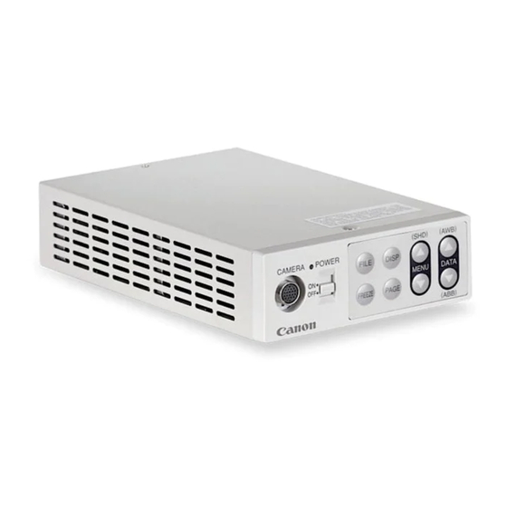
4. NAMES AND FUNCTIONS FILE button DISP button POWER switch MENU UP (SHD) button POWER LED DATA UP (AWB) button Camera cable for “IK-4KH” DATA DOWN FREEZE terminal (ABB) button MENU DOWN button FREEZE button PAGE button [Front] 3G/HD-SDI DC IN 12V DC IN 12V terminal 3G/HD-SDI A, B, C, D terminal... -
Page 8: Connection
5. 1. 1 In case output mode is 4K Lens Coaxial cable × 4, 75 (commercial (commercial 3G/HD-SDI IK-4KE product) product) Camera Cable for IK-4KE Camera Camera Control unit Head (option) DC IN 12V IK-4KH (option) 4K monitor DC power supply 3G-SDI ×... -
Page 9: 1080 I/P Mode
5. 1. 2 In case output mode is 1080p or 1080i Lens Coaxial cable, 75 (commercial (commercial IK-4KE product) product) Camera Cable 3G/HD-SDI for IK-4KE Camera Camera DC IN 12V Control unit Head (option) IK-4KH (option) SDI monitor DC power supply... -
Page 10: Connector Pin Assignments
5. 3 Connector Pin Assignments The rear panel of the camera control unit has the following connectors: DC IN 12V; REMOTE; SYNC IN/OUT and 3G/HD-SDI A, B, C, D terminals. Use the appropriate cables to connect with these connectors. 3G/HD-SDI DC IN 12V SYNC IN/OUT REMOTE... -
Page 11: Operation
6. OPERATION A camera head needs to be connected to this camera control unit from this section on. Refer to the item “5. CONNECTION”, connect the equipment correctly. Turn on the connected equipment and the camera. When using the camera for the first time and when replacing the camera head, be sure to perform the ABB adjustment, refer to the item “6.1 Automatic Black Balance”. - Page 12 AWB (Automatic white balance) • Set the MODE to AWB on the WHT BAL menu. Change the C.TEMP (color temperature conversion) setting, if necessary. (Refer to the item “7.2 (3) WHT BAL (White balance)”.) 3200K : Appropriate for indoor shooting. 5600K : Appropriate for outdoor shooting.
-
Page 13: Scene File
6. 3 Scene File Five scene files (A, B, C, D, E) are available as user memories for this unit. These are chosen depending on shooting conditions. By using the [FILE] button, the camera operation is changed immediately from the currently selected Scene File to the next. -
Page 14: Shading Correction
6. 5 Shading Correction Due to the lens used or the environmental condition, color shading may occur at the upper and lower edge of the screen. If this happens, the shading correction function can be used to decrease the amount of color shading. For shading correction of the unit, SET (Automatic shading correction), MANUAL (Manual shading correction), and OFF (no shading correction) modes are provided. -
Page 15: Switching Of Video Signal Output
6. 6 Switching of Video Signal Output Switching of OUTPUT modes The image output can be changed between “4K”, “1080p”, or “1080i” by turning on the controller while pushing the [MENU DOWN], [DATA UP], or [DATA DOWN] button. • Turn on the controller while pushing the [MENU DOWN] button. The image output becomes “4K”, and “4K” is displayed on the monitor screen. -
Page 16: Mode Setting By On Screen Display
7. MODE SETTING BY ON SCREEN DISPLAY Various settings can be controlled on the unit by using the on screen menu displayed on the monitor. The contents once set are memorized in the scene files (A, B, C, D, E) selected, so if the power turns off, it is unnecessary to set again when using the unit next time. -
Page 17: Menus
7. 2 Menus Select the menu to change the setting by referring to the item “7.1 Using the Menus”. When the [MENU UP], [MENU DOWN] buttons are pushed, the “ ” on the screen moves up and down. Move the “ ” to the item whose setting you wish to change. Use the [DATA UP], [DATA DOWN] buttons to make changes. -
Page 18: (1. 1) Changing The Setting In Auto Mode
(1. 1) Changing the setting in AUTO mode Move up and down Select the desired by pushing value by pushing Shutter mode AUTO, MANUAL, SS MENU UP, DOWN DATA UP, DOWN Video level adjustment -100 to 100 Exposure metering PEAK/AVE, MEDIAN -- 1 SHUTTER -- (FILE A) Peak and average ratio adjustment 00 10 to 10 00 MODE... - Page 19 (e) Changing the automatic shutter zone area Move the “ ” to AREA by pushing the [MENU UP], [MENU DOWN] buttons. Select the measurement light area by pushing the [DATA UP], [DATA DOWN] buttons. [DATA UP] PRESET A PRESET B PRESET C PRESET D PRESET E...
-
Page 20: (1. 2) Changing The Setting In Manual Mode
(1. 2) Changing the setting in MANUAL mode Move up and down Select the desired by pushing value by pushing MENU UP, DOWN DATA UP, DOWN Shutter mode AUTO, MANUAL, SS -- 1 SHUTTER -- (FILE A) Shutter speed setting MODE MANUAL OFF, 1/100s, 1/125s, 1/250s, 1/500s, 1/1000s,... -
Page 21: ( 2 ) Gain (Video Gain)
( 2 ) GAIN (Video gain) GAIN has three modes; AUTO, MANUAL, OFF. Move the “ ” to MODE, push the [DATA UP], [DATA DOWN], and select one of the three modes: AUTO, MANUAL, OFF. In the OFF mode, gain is fixed to 0dB. (2. -
Page 22: ( 3 ) Wht Bal (White Balance)
Move the “ ” to MANUAL by pushing the [MENU UP], [MENU DOWN] buttons. Select the desired value of manual gain by pushing the [DATA UP], [DATA DOWN] buttons. [DATA UP] -6dB 24dB [DATA DOWN] ( 3 ) WHT BAL (White balance) The WHT BAL has two modes;... -
Page 23: (3. 2) Changing Gain In Manual Mode
The dark squares indicate the effective region of the image, which is divided into an 8 x 8 grid. PRESET A PRESET B PRESET C PRESET D Custom Selection PRESET E USER (e) Confirming the contents of the zone area selected by AWB Move the “... -
Page 24: 4 ) Process1
( 4 ) PROCESS1 Move up and down by Select the desired value by pushing MENU UP, DOWN pushing DATA UP, DOWN Gamma correction ON, OFF -- 4 PROCESS1 -- (FILE A) Gamma correction level setting -10 to 10 Black gamma correction setting LOW, NORMAL, HIGH GAMMA ON/OFF GAMMA Knee correction point 70 to 100%... -
Page 25: (4. 3) Changing Black Gamma Correction Level
(4. 3) Changing black gamma correction level Move the “ ” to BLACK GAMMA by pushing the [MENU UP], [MENU DOWN] buttons. Select black gamma correction by pushing the [DATA UP], [DATA DOWN] buttons. [DATA UP] NORMAL HIGH [DATA DOWN] * When OFF is selected in GAMMA ON/OFF selection line, the display BLACK GAMMA turns off automatically, so the black gamma correction level cannot be changed. -
Page 26: (4. 6) Changing Pedestal
(4. 6) Changing pedestal (a) Changing master pedestal Move the “ ” to M. PED by pushing the [MENU UP], [MENU DOWN] buttons. Select the desired value of the master pedestal by pushing the [DATA UP], [DATA DOWN] buttons. [DATA UP] M. -
Page 27: 5 ) Process2
( 5 ) PROCESS2 Move up and down by Select the desired value by pushing MENU UP, DOWN pushing DATA UP, DOWN Detail gain setting 0 to 31 -- 5 PROCESS2 -- (FILE A) DTL GAIN Detail boost frequency 1 to 16 DTL FREQ HV BALANCE 16/16... -
Page 28: 6 ) Process3
( 6 ) PROCESS3 Move up and down by Select the desired value by pushing MENU UP, DOWN pushing DATA UP, DOWN Matrix color correction ON, OFF -- 6 PROCESS3 -- (FILE A) MATRIX Selection of correction color R, R-Ye, Ye, Ye-G, G, G-Cy, COLOR C, Cy-, B, B-Mg, Mg, Mg-R Phase setting -15 to 15... -
Page 29: 7 ) Sync
( 7 ) SYNC When an external sync signal is input, the display changes from INT (internal sync) to EXT. (external sync) automatically. (7. 1) INT screen Sync system display -- 7 SYNC -- (FILE A) MODE (7. 2) Changing EXT. setting Move up and down Select the desired by pushing... -
Page 30: 8 ) Option
( 8 ) OPTION Move up and down by Select the desired value by pushing MENU UP, DOWN pushing DATA UP, DOWN SHADING MODE OFF, SET, MANUAL -- 8 OPTION (FILE A) SHADING DTL OUT Detail signal output ON, OFF FLIP Vertical inversion ON, OFF MIRROR... -
Page 31: (8. 4) Change Of Vertical Inversion Setting
(8. 4) Change of vertical inversion setting Move the “ ” to FLIP by pushing the [MENU UP], [MENU DOWN] buttons. Select ON (Vertical inversion image appears.) or OFF by pushing the [DATA UP], [DATA DOWN] buttons. (8. 5) Change of horizontal inversion setting Move the “... -
Page 32: (8. 8) Changing 4K Osd (On Screen Display) Output
(8. 8) Changing 4K OSD (On Screen Display) output Use the [MENU UP] and [MENU DOWN] buttons to move “ ” to OSD OUTPUT. Use the [DATA UP] and [DATA DOWN] buttons to select a letter from A to D. [DATA UP]... -
Page 33: 9 ) Setting User Area
( 9 ) Setting USER area • When USER is selected for the AREA of the automatic shutter or for AWB, the light measurement zones can be changed. • The USER area is composed of 64 zones with 8 (vertical) x 8 (horizontal) areas, and each area can be set to ON/ OFF. -
Page 34: 10 ) Returning To Factory Settings
( 10 ) Returning to factory settings The contents set of each scene file can be returned to the factory default status (preset status). (1) Select a scene file to set to the factory default status by pressing the [FILE] button. (2) If the color bar pattern or characters are displayed on the screen, press the [DISP] button to disable the color bar pattern and character display. -
Page 35: Before Making Service Call
8. BEFORE MAKING SERVICE CALL Symptom Items to be checked No image • Is power supplied correctly? • Is the power switch on, and the power LED illuminated? • Is the lens iris adjusted correctly? • Are the camera and video cables connected correctly? •... -
Page 36: Specifications
9. SPECIFICATIONS * These conditions are only satisfied when the camera control unit is connected to camera head model # IK-4KH. Power supply DC 12 V ± 10 % Power consumption Approx. 13.8W (including the camera head) (with the power supply voltage of 12V) Pickup system RGB, 3CMOS, Micro prism system Image sensor... -
Page 37: External Appearance Diagram
10. EXTERNAL APPEARANCE DIAGRAM Unit : mm [inch] 12.5 [0.49] 196 [7.72] FREEZE [Front] 4-M3 BD 3G/HD-SDI DC IN 12V SYNC IN/OUT REMOTE KEY LOCK FORMAT SYNC 59.94 [Rear] 139 ± 0.15 [5.47 ± 0.006] [1.06]... - Page 38 (option). Please do not connect it to other equipment. Front Side ( hole) 39.5 [1.56] • Read the “CAUTIONS ON USE AND INSTALLATION” in the instruction manual of IK-4KE and follow them. 4.5[0.18] 22[0.87] • This camera is for indoor use only. 3.5[0.14] 22[0.87]...