Table of Contents
Advertisement
Service Manual
The service information is designed for experienced repair technicians only and is not designed for use by the general
public. It does not contain warnings or cautions to advise non-technical individuals of potential dangers in attempting
to service a product. Products powered by electricity should be serviced or repaired only by experienced professional
technicians. Any attempt to service or repair the product or products dealt within this service information by anyone
else could result in serious injury or death.
There are special components used in this equipment which are important for safety. These parts are marked by
in the Schematic Diagrams, Circuit Board Diagrams, Exploded Views and Replacement Parts List. It is essential that
these critical parts should be replaced with manufacturer's specifi ed parts to prevent shock, fi re or other hazards. Do
not modify the original design without permission of manufacturer.
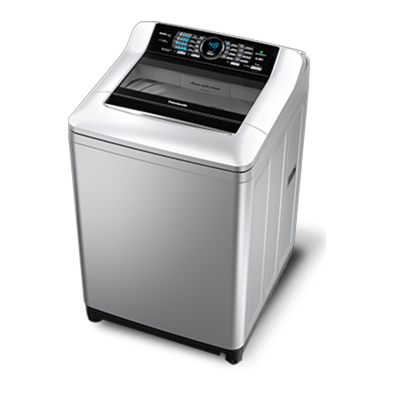
Fully Automatic Washing Machine
WARNING
IMPORTANT SAFETY NOTICE
Order No. PAPTH141101CE
© Panasonic Appliances (Thailand) Co., Ltd. 2014.
All rights reserved. Unauthorized copying and
distribution is a violation of law.
NA-F135X1
NA-F115X1
NA-F135A1
NA-F125A1
NA-F115A1
Product Colour
Stainless Colour (L)
Silver (S)
White (W)
Destination
Thailand, Malaysia
Singapore (Local)
Singapore (Export)
Vietnam
Advertisement
Table of Contents

Related Manuals for Panasonic NA-F135X1


Summary of Contents for Panasonic NA-F135X1
-
Page 1: Service Manual
Schematic Diagrams, Circuit Board Diagrams, Exploded Views and Replacement Parts List. It is essential that these critical parts should be replaced with manufacturer’s specifi ed parts to prevent shock, fi re or other hazards. Do not modify the original design without permission of manufacturer. © Panasonic Appliances (Thailand) Co., Ltd. 2014. All rights reserved. Unauthorized copying and distribution is a violation of law. -
Page 2: Table Of Contents
13 - 14 11. Troubleshooting 12. Table of Errors 12.1 U-Error indication 12.2 H-Error indication 13. Wiring Diagram 13.1 NA-F135X1, NA-F115X1 13.2 NA-F135A1, NA-F125A1, NA-F115A1 14. Disassembly 14.1 Controller Unit 14.2 Panel Face B 15. Parts exploded view and replacement Parts List 15.1 Parts exploded view : Part A... -
Page 3: Attention In The Repair Work Security
1. ATTENTION IN THE REPAIR WORK SECURITY In order to prevent any accident during repair work and ensure security of the product after repair work, somethings surely followed are explained below. The level of the arised damages or dangers, when indicated contents are ignored, are classified by following indications and explained. -
Page 4: Parts Identification
2. PARTS IDENTIFICATION Operation Panel Leveller Softener case Lint filter Power cord and plug Detergent Pulsator inlet Adjustable leg External drain water hose Water supply valve Accessories ● Water supply hose ● Water tap adaptor ● External drain water hose • Length: 1.0 m ●... -
Page 5: Specifications
3. SPECIFICATIONS Model NA-F135X1 NA-F115X1 NA-F135A1 NA-F125A1 NA-F115A1 Model Code W8XT W8XV W8XW W8XX W8XY 220V/50Hz TH-C3,VN-C2,RBD-S3 TH-C3,VN-C2 TH-C3,RBD-S3 TH-C3 TH-C3,VN-C2 Rate voltage and Frequency 230V/50Hz SG-S3 SG-S3 SG-S3 SG-S3 SG-S3,RBD-S3 240V/50Hz MY-S3 MY-S3 Body Colour Stainless Silver White White... -
Page 6: Technical Information 4.1 Standard Wash Capacity
4. TECHNICAL INFORMATION 4.1 Standard Wash Capacity MAXIMUM CAPACITY COURSE NA-F135X1 NA-F125A1 NA-F115X1 NA-F135A1 NA-F115A1 NORMAL 13.5 kg 12.5 kg 11.5 kg SPEEDY 13.5 kg 12.5 kg 11.5 kg DELICATE 5.0 kg 5.0 kg 5.0 kg BABY-CARE 13.5 kg 12.5 kg 11.5 kg... -
Page 7: Installation 5.1 Check The Location
5. INSTALLATION 5.1 Check the location. ■ Avoid the following locations for installation. • Locations with a possibility of freezing • Damp locations or locations where it may be Water supply exposed to rain, etc. valve screw (To prevent electric shock or fire) • Locations exposed to direct sunlight Water tap (To prevent malfunction or deformation) adaptor... -
Page 8: Connect The Water Tap Adaptor And Water Supply Hose
■ If the installation, test run and inspection of the washing machine are not carried out following this installation method, Panasonic will not be liable for any accident or damage caused. 5.4 Connect the water tap adaptor and water supply hose. -
Page 9: Operations Panel
“Water Level”. (Example: For NA-F135X1, After approx. 5 seconds, indicates “High” has 93 L, 86 L and 81 L options.) the approximate remaining time (min). -
Page 10: Washing
7. WASHING Preparation: ● Check if the washing machine is properly installed. (P.7) ● Turn on the water faucet. Timer preset After loading laundry Turn the power on. Set how many hours later to finish ● The Normal program is selected when the power is turned on. -
Page 11: Washing Options
8. WASHING OPTIONS Delicate ECONAVI Use this program to gently wash delicate (NA-F135X1 / NA-F115X1) clothes and stylish garments. Available in the Normal program, this function Load laundry evenly. automatically adjusts the operation time and ● Load items that easily float first, water amount according to the detected amount and press them from above. -
Page 12: Maintenance
9. MAINTENANCE Cancelling end buzzer Lint filter After each operation Pressing down, Lint filter press. Then hold on for 2 short 3 seconds. beeps 4 short Remove the ● To reset, do the same procedure. beeps filter. Setting Child Lock To prevent children from falling into the tub and drowning, if the lid is opened while the washing machine is operating, this function sounds a buzzer Open the filter... -
Page 13: Test Mode
10. TEST MODE Fig-1 Fig-2 - Set the power switch to "off" as Fig-1. - Press and hold both the "Water level" and "Wash" buttons with one hand. - Press the power swith to "on". - Release your fingers from the buttons and power switch which you pressed same as Fig-2. - Within three seconds press the "Water level" button to set the desire check procedure. (Check Contents as press button step by step : A,B,C,E M,G and H) Number of timers Check... - Page 14 ●Set to initial mode ●In case to change PCB or for tension of belt move V-belt. Set the V-belt tension to initial mode for using below procedure. ●The initial display will be indicated “b0”, after that press “Start/Pause” button once, it shall be listened click sound six times to set properly. ●Indicate the error ●”Digit lights” shall be indicate message of the last...
-
Page 15: Troubleshooting
11. TROUBLESHOOTING Symptoms Points to be checked Time indication increases or ● Time indication is approximate. Remaining time is corrected during operation and displayed. does not decrease Operation time is longer than ● The operation time may be longer if laundry is concentrated the time indication. -
Page 16: Table Of Errors 12.1 U-Error Indication
12. TABLE OF ERRORS 12.1 U-Error indication ● If there is an operation error or if there is a problem with the washing machine, such as faulty draining, spining etc; operation will stop, the warning buzzer will sound, and an error indication will be displayed. - All the switchs cannot be operated. - An error indication will be displayed. Indication Content Check Point Method to clear Water can not drain ●Check at drain water hose, clogged or not? ●Resume operation by ●Check at hose tip under water flow. opening and closing ●Check at drain hose raised higher than 10 cm. -
Page 17: H-Error Indication
12.2 H-Error indication ● If there is an operation error or if there is a problem with the washing machine, - All the switchs cannot be operated. - An error indication will be displayed. Indication Content Check Point Method to clear Water level sensor ●Disconnect the power ●Check at condition of the connector error plug--->plug in ●Replace the Pressure sensor switch ●Replace PCB board Motor triac error ●Disconnect the power ●In water drain action check both side of plug--->plug in capacitor that voltage not equal to “0”... -
Page 18: Wiring Diagram 13.1 Na-F135X1, Na-F115X1
13. WIRING DIAGRAM 13.1 NA-F135X1, NA-F115X1 13.2 NA-F135A1, NA-F125A1, NA-F115A1 - 18 -... -
Page 19: Disassembly 14.1 Controller Unit
14. DISASSEMBLY 14.1 Controller Unit Fig.1 Fig.2 Fig.3 Fig.4 - Use Screw drive (+) take off screws at Panel A as Fig.1 - Pull off Insulation Spacer A loose from lock of Controller Unit as Fig.2 - Use Screw driver (+) take off screws at Controller Unit with Panel Face B as Fig.3 - Change new part of Controller Unit as Fig.4 14.2 Panel Face B Fig.5... -
Page 20: Parts Exploded View And Replacement Parts List 15.1 Parts Exploded View : Part A
15. PARTS EXPLODED VIEW AND REPLACEMENT PARTS LIST 15.1 Parts Exploded View : Part A - 20 -... - Page 21 15.2 Replacement Parts List Parts List - Part A F135X1 F135A1 F125A1 F115X1 F115A1 Ref. Part Name Part No. Safety Remark SIN- SIN- SIN- SIN- SIN- SIN- SIN- SIN- BODY B AXW01028XT0L STAINLESS COLOUR AXW01028XT0W WHITE AXW01028XT0S SILVER PANEL FACE B AXW01468XT00 ENGLISH/THAI AXW01468XT10...
-
Page 22: Parts Exploded View : Part B
15.3 Parts Exploded View : Part B B21-1 B18-1 B21-1 Accessories - 22 -... - Page 23 15.4 Replacement Parts List Parts List - Part B F135X1 F135A1 F125A1 F115X1 F115A1 Ref. Part Name Part No. Safety Remark SIN- SIN- SIN- SIN- SIN- SIN- SIN- SIN- BODY A UNIT AXW001A8XT0L AXW001A8XT1L FOR EXTERNAL EARTH AXW001A8XT0W AXW001A8XT1W FOR EXTERNAL EARTH AXW001A8XT0S AXW001A8XT1S FOR EXTERNAL EARTH...
-
Page 24: Parts Exploded View : Part C
15.5 Parts Exploded View : Part C C30-1 C30-2 C30-3 BLACK C30-4 GREEN C30-5 C30-6 C30-7 GRAY BLACK - 24 -... - Page 25 15.6 Replacement Parts List Parts List - Part C F135X1 F135A1 F125A1 F115X1 F115A1 Ref. Part Name Part No. Safety Remark SIN- SIN- SIN- SIN- SIN- SIN- SIN- SIN- OUTER TUB COVER AXW32248XT10 O-RING AXW02577BK00 PULSATOR UNIT AXW005D8XT00 X1 SERIES/STAINLESS PULSATOR AXW05018XW00 A1 SERIES/WHITE...
-
Page 26: Parts Exploded View : Packing
15.7 Parts Exploded View : Packing Accessories THIS PART USE FOR PACKING, NOT PART OF PRODUCT. - 26 -... - Page 27 15.8 Replacement Parts List Parts List - Packing F135X1 F135A1 F125A1 F115X1 F115A1 Ref. Part Name Part No. Safety Remark SIN- SIN- SIN- SIN- SIN- SIN- SIN- SIN- PROTECTION CASE A AXW90018XT10 THAI AXW90018XT60 ENGLISH CASE PLATE A AXW91188XT00 AXW91188XV00 AXW91188XW00 AXW91188XX00 AXW91188XY00...