Siemens SIMATIC RF600 System Manual
Hide thumbs
Also See for SIMATIC RF600:
- System manual (506 pages) ,
- Configuration manual (294 pages) ,
- Compact operating instructions (3 pages)
Table of Contents

Related Manuals for Siemens SIMATIC RF600


Summary of Contents for Siemens SIMATIC RF600
- Page 1 Introduction Safety Information System overview SIMATIC RF600 RF600 system planning RFID systems RF600 RF660R reader Antennas System Manual Transponder/tags Accessories Appendix 09/2005 Edition, J31069 D0171-U001-A0-7618...
- Page 2 Trademarks All names identified by ® are registered trademarks of the Siemens AG. The remaining trademarks in this publication may be trademarks whose use by third parties for their own purposes could violate the rights of the owner.
-
Page 3: Table Of Contents
Preface............................1-1 Navigating in the system manual ....................1-3 Safety Information........................... 2-1 General safety instructions ......................2-1 System overview............................. 3-1 RF System SIMATIC RF600...................... 3-1 3.1.1 Application areas of RF600......................3-2 3.1.2 Features ............................. 3-3 RF600 system planning .......................... 4-1 Overview ............................ - Page 4 Table of contents 5.1.2 Design of the RF660R reader ....................5-3 5.1.3 Status displays ........................... 5-4 5.1.4 Pin assignment of the serial interfaces ..................5-5 5.1.5 Pin assignment and connections of the digital I/O interface ............5-6 5.1.6 Power supply..........................5-8 5.1.7 Grounding connection ........................
- Page 5 Table of contents RF600 System Manual, 09/2005 Edition, J31069 D0171-U001-A0-7618,...
-
Page 7: Introduction
Where this documentation is valid This documentation is valid for all supplied variations of the SIMATIC RF600 system and describes the state of delivery as of September 2005. Conventions The following terms/abbreviations are used synonymously in this document: •... - Page 8 Introduction 1.1 Preface Observance of installation guidelines The installation guidelines and safety instructions given in this documentation must be followed during commissioning and operation. RF600 System Manual, 09/2005 Edition, J31069 D0171-U001-A0-7618,...
-
Page 9: Navigating In The System Manual
System overview Overview of all RF identification systems, system overview of SIMATIC RF600 RFID system planning Information about possible applications of SIMATIC RF600, support for application planning, tools for finding suitable SIMATIC RF600 components. - Page 10 Introduction 1.2 Navigating in the system manual RF600 System Manual, 09/2005 Edition, J31069 D0171-U001-A0-7618,...
-
Page 11: Safety Information
Safety Information General safety instructions Caution Please observe the safety instructions on the back cover of this documentation. SIMATIC RFID products comply with the salient safety specifications to IEC, EN, UL and CSA. If you have questions about the admissibility of the installation in the designated environment, please contact your service representative. - Page 12 Safety Information 2.1 General safety instructions System expansion Only install system expansion devices designed for this device. If you install other upgrades, you may damage the system or violate the safety requirements and regulations for radio frequency interference suppression. Contact your technical support team or your sales outlet to find out which system upgrades are suitable for installation.
-
Page 13: System Overview
System overview RF System SIMATIC RF600 SIMATIC RF600 is an identification system that operates in the UHF range. UHF technology supports large write/read distances with passive tags. The SIMATIC RF660-R read/write devices (readers), fitted for example on the gate of a warehouse, automatically record every movement of goods, and signal these to the host systems. -
Page 14: Application Areas Of Rf600
System overview 3.1 RF System SIMATIC RF600 3.1.1 Application areas of RF600 RFID (radio frequency identification) permits interruption-free tracking and documentation of all delivered, stocked and shipped goods in the incoming goods, warehouse, production logistics and distribution departments. A small data medium - referred to as SmartLabel or tag - is adhered to every item, package or palette, and contains all important information. -
Page 15: Features
System overview 3.1 RF System SIMATIC RF600 3.1.2 Features The RF600 identification system has the following performance features: RFID system RF600 Type Contactless RFID (Radio Frequency IDentification) system in the UHF band Transmission frequency 865-868 MHz (Europe) 902-928 MHz (USA) Read/write distance Europe: <... - Page 16 System overview 3.1 RF System SIMATIC RF600 RF600 System Manual, 09/2005 Edition, J31069 D0171-U001-A0-7618,...
-
Page 17: Rf600 System Planning
RF600 system planning Overview You should observe the following criteria for implementation planning: • Antenna configurations • Environmental conditions for transponders • The response of electromagnetic waves in the UHF band • EMC directives RF600 System Manual, 09/2005 Edition, J31069 D0171-U001-A0-7618,... -
Page 18: Antenna Configurations
RF600 system planning 4.2 Antenna configurations Antenna configurations 4.2.1 Antenna configuration example The following diagram shows an example of a portal configuration. The antenna are positioned at the height at which the tags are expected which are to be identified. The maximum width of the portal that is recommended for reliable operation is 4 m. -
Page 19: Possibilities And Application Areas For Antenna Configurations
RF600 system planning 4.2 Antenna configurations 4.2.2 Possibilities and application areas for antenna configurations Some basic antenna configurations and possible fields of application are shown below. Antenna configuration 1: Description/ application areas This arrangement of antennas is appropriate when the tags to be read are only located on one side of the items to be identified, e.g. - Page 20 RF600 system planning 4.2 Antenna configurations Antenna configuration 3: Description/ application areas Preferred application: In the identification of goods in loading portals. Similar to configuration 2, but with additional reading reliability when the tag is at an angle to the vertical. ①...
- Page 21 RF600 system planning 4.2 Antenna configurations Antenna configuration 5: Description/ application areas Preferred application: In the identification of goods in loading portals. Similar to configuration 4, but the reliability of tag identification is improved as a result of the four antennas at separate locations, so the tag position is not critical.
-
Page 22: Tag Orientation In Space
RF600 system planning 4.2 Antenna configurations 4.2.3 Tag orientation in space The alignment of the tag antenna to the antenna of the reader affects the reading range. For maximum performance and to achieve the maximum reading range, the tag antenna should therefore be aligned in parallel with the reader antenna: Parallel tag alignment Large reading range... -
Page 23: Specified Minimum And Maximum Spacing Of Antennas
RF600 system planning 4.2 Antenna configurations 4.2.4 Specified minimum and maximum spacing of antennas Specified minimum spacing of antennas The following diagram shows the specified minimum and maximum spacings for mounting antennas: A minimum spacing of 50 cm is necessary between the antenna and liquids or metals. The distance between the antenna and the floor should also be at least 50 cm. - Page 24 RF600 system planning 4.2 Antenna configurations Figure 4-3 Antennas mounted adjacently horizontally or vertically For a portal configuration, the distance between two antennas that are connected to the same reader is up to 3.5 m (in Europe) or 4 m (in the USA). Figure 4-4 Portal configuration RF600...
-
Page 25: Mutual Interference Of Readers (Antennas)
RF600 system planning 4.2 Antenna configurations 4.2.5 Mutual interference of readers (antennas) Using more than one reader When several RFID readers are used, there is a danger that RFID tags can also be read by other readers. It must be ensured that the tag can only be identified by the appropriate reader. -
Page 26: Reading Range
RF600 system planning 4.2 Antenna configurations 4.2.6 Reading range The reading range between the reader (antenna) and the transponder is affected by the following factors: The reading range depends on Description Transmit power of the reader The higher the transmit power of the reader, the larger the reading range. -
Page 27: Increasing The Probability Of Identification For Tags - Antenna Switching
RF600 system planning 4.2 Antenna configurations 4.2.7 Increasing the probability of identification for tags - Antenna switching To achieve a high probability of reading tags, the antenna switching function has been implemented in the RF600R reader: At a given time, the system transmits on one antenna and receives on the other antennas. As long as the antenna is receiving signals from further tags, the system continues to transmit on the same transmit antenna until all responding tags have been identified. -
Page 28: Environmental Conditions For Transponders
RF600 system planning 4.3 Environmental conditions for transponders Environmental conditions for transponders 4.3.1 Basic rules The transponder must not be placed directly on metal surfaces or on containers of liquid. For physical reasons, a minimum distance must be maintained between the tag antenna and conductive material. -
Page 29: The Response Of Electromagnetic Waves In The Uhf Band
RF600 system planning 4.4 The response of electromagnetic waves in the UHF band The response of electromagnetic waves in the UHF band 4.4.1 The effect of reflections and interference Reflections and interference Electromagnetic waves in the UHF band behave and propagate in a similar manner to light waves, that is they are reflected from large objects such as ceilings, floors, walls and windows and interfere with each other. -
Page 30: Influence Of Metals
RF600 system planning 4.4 The response of electromagnetic waves in the UHF band 4.4.2 Influence of metals Metal can have an effect on the electromagnetic field depending on the arrangement or environment. The effect ranges from a hardly determinable influence through to total blocking of communication. -
Page 31: Influence Of Liquids And Non-Metallic Substances
RF600 system planning 4.4 The response of electromagnetic waves in the UHF band 4.4.3 Influence of liquids and non-metallic substances Non-metallic substances can also affect the propagation of electromagnetic waves. When non-metallic substances or objects are located in the propagation field that can absorb UHF radiation, these can alter the antenna field depending on their size and distance and can even extinguish the field entirely. -
Page 32: Regulations Applicable To Frequency Bands
RF600 system planning 4.5 Regulations applicable to frequency bands Regulations applicable to frequency bands 4.5.1 Regulations for UHF frequency bands in Europe Regulations for frequency bands according to EN 302 208 ETSI (European Telecommunications Standards Institute) Specifications of European standard EN 302 208: •... - Page 33 RF600 system planning 4.5 Regulations applicable to frequency bands Channel assignment • The UHF band from 865 to 868 MHz is subdivided into three sub bands: Sub bands Frequency range Output 865.0 to 865.5 MHz 0.1 W ERP 865.6 to 867.6 MHz 2,0 W ERP 867.6 to 868.0 MHz 0,5 W ERP...
-
Page 34: Regulations For Uhf Frequency Bands In The Usa
RF600 system planning 4.5 Regulations applicable to frequency bands 4.5.2 Regulations for UHF frequency bands in the USA FCC (Federal Communications Commission) • UHF band: 902 to 928 MHz • Radiant power: max. 4 W (EIRP) • Number of channels: 50 •... -
Page 35: Guidelines For Electromagnetic Compatibility (Emc)
RF600 system planning 4.6 Guidelines for electromagnetic compatibility (EMC) Guidelines for electromagnetic compatibility (EMC) 4.6.1 Overview These EMC Guidelines answer the following questions: • Why are EMC guidelines necessary? • What types of external interference have an impact on the system? •... -
Page 36: What Does Emc Mean
RF600 system planning 4.6 Guidelines for electromagnetic compatibility (EMC) 4.6.2 What does EMC mean? The increasing use of electrical and electronic devices is accompanied by: • Higher component density • More switched power electronics • Increasing switching rates • Lower power consumption of components due to steeper switching edges The higher the degree of automation, the greater the risk of interaction between devices. - Page 37 RF600 system planning 4.6 Guidelines for electromagnetic compatibility (EMC) Shielding by enclosure • Protect the device against external interference by installing it in a cabinet or housing. The housing or enclosure must be connected to the chassis ground. • Use metal plates to shield the device against electromagnetic fields. •...
- Page 38 RF600 system planning 4.6 Guidelines for electromagnetic compatibility (EMC) Shielding for the cables • Shield the data cables and connect the shield at both ends. • Shield the analog cables and connect the shield at one end, e.g. on the drive unit. •...
-
Page 39: Propagation Of Electromagnetic Interference
RF600 system planning 4.6 Guidelines for electromagnetic compatibility (EMC) 4.6.4 Propagation of electromagnetic interference Three components have to be present for interference to occur in a system: • Interference source • Coupling path • Interference sink Figure 4-5 Propagation of interference If one of the components is missing, e.g. - Page 40 RF600 system planning 4.6 Guidelines for electromagnetic compatibility (EMC) Interference sources In order to achieve a high level of electromagnetic compatibility and thus a very low level of disturbance in a plant, it is necessary to recognize the most frequent interference sources. These must then be eliminated by appropriate measures.
- Page 41 RF600 system planning 4.6 Guidelines for electromagnetic compatibility (EMC) What interference can affect RFID? Interference source Cause Remedy Switched-mode power supply Interference emitted from the Replace the power supply current infeed Interference injected through Cable is inadequately Better cable shielding the cables connected in shielded series...
- Page 42 RF600 system planning 4.6 Guidelines for electromagnetic compatibility (EMC) Coupling paths A coupling path has to be present before the disturbance emitted by the interference source can affect the system. There are four ways in which interference can be coupled in: Figure 4-6 Ways in which interference can be coupled in When RFID modules are used, different components in the overall system can act as a...
-
Page 43: Prevention Of Interference Sources
RF600 system planning 4.6 Guidelines for electromagnetic compatibility (EMC) 4.6.5 Prevention of interference sources A high level of immunity to interference can be achieved by avoiding interference sources. All switched inductances are a frequent source of interference in plants. Suppression of inductance Relays, contactors, etc. -
Page 44: Equipotential Bonding
RF600 system planning 4.6 Guidelines for electromagnetic compatibility (EMC) 4.6.6 Equipotential bonding Potential differences between different parts of a plant can arise due to the different design of the plant components and different voltage levels. If the plant components are connected across signal cables, transient currents flow across the signal cables. -
Page 45: Cable Shielding
RF600 system planning 4.6 Guidelines for electromagnetic compatibility (EMC) 4.6.7 Cable shielding Signal cables must be shielded in order to prevent coupling of interference. The best shielding is achieved by installing the cables in steel tubes. However, this is only necessary if the signal cable is routed through an environment prone to particular interference. - Page 46 RF600 system planning 4.6 Guidelines for electromagnetic compatibility (EMC) Cable tie Figure 4-10 Connection of shielding bus The shielding bus must be connected to the PE busbar. If shielded cables have to be interrupted, the shield must be continued via the corresponding connector housing.
-
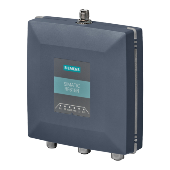
Page 47: Rf660R Reader
RF660R reader Description SIMATIC RF660R is a stationary reader for connecting up to 4 external antennas. A rugged housing with high IP65 degree of protection means that the device is a universal and reliable partner in harsh production environments, on conveyor systems, in warehouses, or directly at the loading gate. -
Page 48: Ordering Data
RF660R reader 5.1 Description 5.1.1 Ordering data Description Machine-Readable Product Code SIMATIC RF660R RF600 System Manual, 09/2005 Edition, J31069 D0171-U001-A0-7618,... -
Page 49: Design Of The Rf660R Reader
RF660R reader 5.1 Description 5.1.2 Design of the RF660R reader Item Description Status LED Industrial Ethernet (RJ45 connector) RS 422 interface (8-pin M12 connector) RS 232 interface (5-pin M12 connector) Digital I/O (8-pin M12 connector) Power, 24 V DC; (4-pin M12 connector) Description 4 antenna connections ANT 1 to ANT 4 (RTNC connector) -
Page 50: Status Displays
RF660R reader 5.1 Description 5.1.3 Status displays Status displays LEDs Color Meaning Power on Green Power supply ON (also lit for undervoltage/overvoltage) Tag Detect Yellow LED is lit as soon as any tag is in the field System Error Reader is not active. Rebooting is necessary (operating voltage Off →... -
Page 51: Pin Assignment Of The Serial Interfaces
RF660R reader 5.1 Description 5.1.4 Pin assignment of the serial interfaces RS 422 connector Meaning not connected RS422_RX_PLUS RS422_RX_MINUS RS422_TX_MINUS RS422_TX_PLUS housing RS 232 connector Meaning RS232_TX RS232_RX not connected not connected not connected Industrial Ethernet Meaning Transmit Data (+) Transmit Data (-) Receive Data (+) Terminated... -
Page 52: Pin Assignment And Connections Of The Digital I/O Interface
RF660R reader 5.1 Description 5.1.5 Pin assignment and connections of the digital I/O interface Pin assignment Digital I/O socket Meaning Input USER_IN (0) Input USER_IN (1) Input USER_IN (2) GND (IN) Output USER_OUT (0) Output USER_OUT (1) Output USER_OUT (2) Housing RF600 System Manual, 09/2005 Edition, J31069 D0171-U001-A0-7618,... - Page 53 RF660R reader 5.1 Description Connections Figure 5-2 Connections for digital I/O Output USER_OUT (0), (1), (2): (1) These are high-side switches that switch V (+24V) at low resistance ('active high'). (2) Each output is rated for 0.5 A current and is electronically protected. (3) The 0 V rail is Pin 4 (GND).
-
Page 54: Power Supply
RF660R reader 5.1 Description 5.1.6 Power supply Pin assignment of the power connections Power connector Meaning Ground (0V) +24 V +24 V Ground (0V) RF600 System Manual, 09/2005 Edition, J31069 D0171-U001-A0-7618,... -
Page 55: Grounding Connection
RF660R reader 5.1 Description 5.1.7 Grounding connection A low-impedance earth connection ensures that interference signals generated, for example, by external power supply cables or signal cables are safely discharged to earth. Required tool for protective earth terminal: TORX T20 screwdriver Ground connection/protective earth terminal The protective earth terminal (M4 threads) (1) on the device (large surface, large-area contact) has... -
Page 56: Installation /Mounting
RF660R reader Installation /Mounting 5.3.1 Mounting/Installation Mounting/installing the device The positions of the fixing holes for the device are shown in the "Dimension drawing" section. Examples of mounting types Material Hole diameter Fixing Concrete 8 mm diameter Rawlplug: 8 mm diameter, 50 mm length 60 mm depth Screws: 4 mm diameter, 50 mm length Plasterboard... - Page 57 RF660R reader 5.4 Configuration/integration • Ethernet • RS 422 and • RS 232 The communication interfaces transfer the data to IT, ERP and SCM systems on SIMATIC PLCs or PCs (also used for configuration and diagnostics). Simple process controls (e.g. a traffic signal) can be directly implemented using the read/write device via three digital inputs and outputs with 24 V each.
-
Page 58: Transmission Protocols
RF660R reader 5.4 Configuration/integration 5.4.2 Transmission protocols Transmission protocols The following transmission protocols are available: 3964R protocol and TCP/IP. RS232 communication XML protocol Transmission rates 115200 bps Start bits Data bits Parity Stop bits RS422 communication 3964R protocol Transmission rate 9600, 19200, 38400, 57600, 115200 bps (autobauding) Start bits... -
Page 59: Maintenance And Service
RF660R reader 5.5 Maintenance and service Maintenance and service RF600 5-13 System Manual, 09/2005 Edition, J31069 D0171-U001-A0-7618,... -
Page 60: Technical Specifications
RF660R reader 5.6 Technical specifications Technical specifications 5.6.1 Technical specifications of RF660R Table 5-1 Technical specifications of RF660R General Technical Specifications Weight 3.7 kg (with cover 3.8 kg) Dimensions (L x W x H) in mm 320 x 145 x 100 without connections Material Aluminum Frequencies... - Page 61 RF660R reader 5.6 Technical specifications Transmission and reading characteristics Max. reads/s EPC Generation 2 ISO 18000-6B Europe - Single Tag • Up to 100 reads/s as part of Up to 100 tips, single tag Note: the collision arbitration cycle only The LBT and frequency channel schedule can affect this >...
- Page 62 RF660R reader 5.6 Technical specifications Radio to R&TTE- guidelines EN 300 330, EN 301 489 Approvals • ????? CE, EMC, FCC, cULus • IEC60950, including US and Canadian variants of it • FCC CFR47 Part 15.247 • ETSI EN 302-208 •...
-
Page 63: Dimension Drawings
RF660R reader 5.7 Dimension drawings Dimension drawings 5.7.1 Dimension drawings Figure 5-4 Dimension drawing of the reader RF600 5-17 System Manual, 09/2005 Edition, J31069 D0171-U001-A0-7618,... -
Page 64: Certificates And Approvals
5.8 Certificates and approvals Certificates and approvals 5.8.1 FCC information Siemens SIMATIC RF660R FCC ID: NXW-RF660 This device complies with Part 15 of the FCC Rules. Operation is subject to the following two conditions: (1) This device may not cause harmful interference, and (2) This device must accept any interference received, including interference that may cause undesired operation. - Page 65 RF660R reader 5.8 Certificates and approvals RF600 5-19 System Manual, 09/2005 Edition, J31069 D0171-U001-A0-7618,...
-
Page 67: Antennas
Antennas RF660A antenna 6.1.1 RF660A description The RF660A is a stationary antenna, specially designed for the RF660R reader. The antenna is available in two different frequency ranges that have been specified for the regions of Europe and USA. Frequency range •... - Page 68 Antennas 6.1 RF660A antenna Radiating/receiving characteristic The characteristic curve is shown for horizontal alignment and for a frequency of 865 MHz. The radiating/receiving angle of the antenna is defined by the angle between the two 3dB points. Figure 6-1 Effective range of radiation (at 865 MHz, horizontal alignment) RF600 System Manual, 09/2005 Edition, J31069 D0171-U001-A0-7618,...
- Page 69 Antennas 6.1 RF660A antenna Ordering data Description Machine-Readable Product Code RF660A for Europe 6GT2 810-0AA00 RF660A for USA 6GT2 810-0AA01 RF600 System Manual, 09/2005 Edition, J31069 D0171-U001-A0-7618,...
-
Page 70: Application Planning
Antennas 6.1 RF660A antenna 6.1.2 Application Planning Specified minimum spacing of antennas The following diagram shows the specified minimum and maximum spacings for mounting antennas: A minimum spacing of 50 cm is necessary between the antenna and liquids or metals. The distance between the antenna and the floor should also be at least 50 cm. - Page 71 Antennas 6.1 RF660A antenna Figure 6-3 Antennas mounted adjacently horizontally or vertically For a portal configuration, the distance between two antennas that are connected to the same reader is up to 3.5 m (in Europe) or 4 m (in the USA). Figure 6-4 Portal configuration RF600...
-
Page 72: Installation /Mounting
Antennas 6.1 RF660A antenna 6.1.3 Installation /Mounting The RF660A antenna can be fixed to any firm support. Mounting types Two systems are available for fixing the antenna: • Rigid fixing with VESA 100 x 100 • Flexible fixing with VESA 75 x 75 Fixing with VESA 100 x 100 Rigid fixing with an antenna adapter plate is suitable for: •... - Page 73 Antennas 6.1 RF660A antenna Antenna with antenna adapter plate Description Dimensions for fixing holes All dimensions in mm RF600 System Manual, 09/2005 Edition, J31069 D0171-U001-A0-7618,...
- Page 74 Antennas 6.1 RF660A antenna Fixing with VESA 75 x 75 Flexible mounting is possible using the VESA 75 x 75 mounting set. VESA 75 x 75 mounting set Description Swivel range of wall mounting Distances for wall mounting VESA adapter plate from VESA 75 x 75 to VESA 100 x 100 RF600...
-
Page 75: Connecting An Antenna To A Reader
The cable between antenna and reader can be up to 20 m in length. Notice Only use original Siemens antenna cables Figure 6-5 Rear of antenna with RTNC connection When less than four antennas are used, we recommend that the antennas are connected to the reader as follows. -
Page 76: Technical Specifications
Antennas 6.1 RF660A antenna 6.1.5 Technical specifications RF660A antenna 865-868 RF660A antenna 902-928 Frequency range 865-868 MHz 902-928 MHz Impedance 50 Ohm nominal 50 Ohm nominal Antenna amplification 5-7 dBil > 6 dBic VSWR 2:1 max. 2:1 max. Polarization RH circular RH circular Radiating/receiving angle 55°-60°... -
Page 77: Transponder/Tags
Transponder/tags Mode of operation of transponders The tag/transponder mainly comprises a microchip with an integral memory and a dipole antenna. The principle of operation of a passive RFID transponder is as follows: • Diversion of some of the high-frequency energy emitted by the reader to supply power to the integral chip •... -
Page 78: Transponder Classes And Generations
Transponder/tags Transponder classes and generations The transponder classes are distinguished by the different communication protocols used between the reader and transponder. Transponder classes are mostly mutually incompatible. The following transponder classes are supported by the RF 600 system: • EPC Global Class 1, 1b with full EPC Global Profile •... - Page 79 Transponder/tags ISO 18000-6 Specification of the transponder/tags in accordance with ISO 18000-6 refers to implementation of the air-interface protocol. There are two versions: ISO 18000-6 Type A and ISO 18000-6 Type B. Type B Type A Frequency range 860 to 960 MHz 860 to 960 MHz Transmission procedure Bi-phase modulation and Manchester...
-
Page 80: Electronic Product Code (Epc)
Transponder/tags Electronic Product Code (EPC) The Electronic Product Code (EPC) supports the unique identification of objects (e.g. retail items, logistical items or transport containers). This makes extremely accurate identification possible. In practical use, the EPC is stored on a transponder (tag) and scanned by the reader. -
Page 81: Accessories
Accessories Accessories Order No. Antenna cable Up to 20 m Cable RS 422: Up to 50 m RS 232: Up to 10 m Ethernet: Up to 20 m Mounting set Yes, 2 different types Further accessories Documentation on CD-ROM Wide-range power supply unit for SIMATIC RF systems RF600 System Manual, 09/2005 Edition, J31069 D0171-U001-A0-7618,... -
Page 82: Wide-Range Power Supply Unit For Simatic Rf Systems
Accessories 8.1 Wide-range power supply unit for SIMATIC RF systems Wide-range power supply unit for SIMATIC RF systems 8.1.1 Features Wide-range power supply unit for RF systems (1) DC output 1 (2) DC output 2 (3) Mains connection Features Wide-range input for use worldwide •... - Page 83 Accessories 8.1 Wide-range power supply unit for SIMATIC RF systems Description The wide-range power supply unit for SIMATIC RF systems is a universal compact power supply and provides the user with an efficient, cost-saving solution for many different mid- range power supply tasks. The primary switched power supply is designed for use on single-phase AC systems.
-
Page 84: Scope Of Supply
Accessories 8.1 Wide-range power supply unit for SIMATIC RF systems 8.1.2 Scope of supply • Wide-range power supply unit for SIMATIC RF systems • 2 m mains cable (country-specific) • Protective cover for flange outlet • Operating instructions 8.1.3 Ordering data Wide-range power supply unit for SIMATIC RF systems (100 - 240 V AC / 24 V DC / 3 A) with 2 m connecting cable with country-specific plug... -
Page 85: Connecting
Accessories 8.1 Wide-range power supply unit for SIMATIC RF systems 8.1.5 Connecting • There are three different (country-specific) mains cables for the EU, UK and US. The appropriate mains cable must be connected to the primary input of the power supply. •... -
Page 86: Technical Specifications
Accessories 8.1 Wide-range power supply unit for SIMATIC RF systems 8.1.6 Technical specifications Table 8-1 General technical specifications Insulation stability (prim./sec.) U 3.3 kV ins p/s Insulation resistance R >1 GΩ Leakage current I = 230 V , f = 50 Hz <... - Page 87 Accessories 8.1 Wide-range power supply unit for SIMATIC RF systems Table 8-3 Technical specifications of the output Output voltage tolerance ∆U = 230 V ≤ +2 %/-1 % outnom Overvoltage protection +20 % typ. out nom Noise ∆U = min., BW: 1 MHz ≤...
-
Page 88: Modification Possibilities
Accessories 8.1 Wide-range power supply unit for SIMATIC RF systems 8.1.7 Modification possibilities • Output voltages • Insulation strength up to 4 kV • Heatsink • DIN rail mounting 8.1.8 Pin assignment of DC outputs and mains connection DC outputs Assignment (1) Ground (0V) (2) +24 V DC... -
Page 89: Dimension Drawing
Accessories 8.1 Wide-range power supply unit for SIMATIC RF systems 8.1.9 Dimension drawing Units of measurement: All dimensions in mm RF600 System Manual, 09/2005 Edition, J31069 D0171-U001-A0-7618,... - Page 90 Accessories 8.1 Wide-range power supply unit for SIMATIC RF systems RF600 8-10 System Manual, 09/2005 Edition, J31069 D0171-U001-A0-7618,...
-
Page 91: Certificates And Approvals
DIN ISO 9001 certificate The quality assurance system for the entire product process (development, production, and marketing) at Siemens fulfills the requirements of ISO 9001 (corresponds to EN29001: 1987). This has been certified by DQS (the German society for the certification of quality management systems.) - Page 92 Appendix A.1 Certificates and approvals One of the following markings on a device is indicative of the corresponding approval: Underwriters Laboratories (UL) to UL 60950 Standard (I.T.E), or to UL508 (IND.CONT.EQ) Underwriters Laboratories (UL) according to Canadian standard C22.2 No. 60950 (I.T.E) or C22.2 No.
- Page 93 Appendix A.1 Certificates and approvals Federal Communications This equipment has been tested and found to comply with the limits for a Commission Class A digital device, pursuant to Part 15 of the FCC Rules. These limits are designed to provide reasonable protection against harmful Radio Frequency interference when the equipment is operated in a commercial Interference Statement...
-
Page 94: Service And Support
• Fax: +49 (0) 180 5050 223 Internet • Visit our site on the Internet at: http://www.siemens.com/automation/service&support • You can send a support query to: http://www.siemens.de/automation/support-request • You can find the latest general information about our identification systems on the Internet at: http://www.siemens.de/simatic-sensors... -
Page 95: Contact Partners
A.3 Contact partners Contact partners If you have any further questions on the use of our products, please contact one of our representatives at your local Siemens office. The addresses are found on the following pages: • On the Internet at: http://www.siemens.com/automation/partner •... - Page 96 Appendix A.4 Training RF600 System Manual, 09/2005 Edition, J31069 D0171-U001-A0-7618,...
- Page 97 Index Accessories of the RF660R reader, 8-1 Gate configuration Antenna configuration, 4-2 Application areas, 4-3 Approvals, A-1 Arrangement of antenna, 4-3 Generations, 7-2 Cable Shielding, 4-29 Identification system Certificates, A-1 Performance Features, 3-3 Classes, 7-2 UHF range, 3-1 Configuration, 5-10 Influence of Antennas, 4-2 Interference, 4-13...
- Page 98 Regulations applicable to UHF frequency bands Status LEDS of the RF660R reader, 5-4 Europe, 4-16 Support, A-4 USA, 4-18 System overview RF600 SIMATIC RF600, 3-1 Main applications, 3-2 System requirements Performance Features, 3-3 RF600, 3-3 System requirements, 3-3 RF660A antenna...