GE C60 Instruction Manual
Breaker protection system
ur series
Hide thumbs
Also See for C60:
- Instruction manual (680 pages) ,
- Communications manual (532 pages) ,
- Instruction manual (604 pages)
Table of Contents
Advertisement
Quick Links
GE
Grid Solutions
GE Grid Solutions
650 Markland Street
Markham, Ontario
Canada L6C 0M1
Tel: +1 905 927 7070 Fax: +1 905 927 5098
Internet:
http://www.GEGridSolutions.com
*1601-0100-AA5*
C60 Breaker Protection System
UR Series Instruction Manual
Manual P/N: 1601-0100-AA5 (GEK-119554D)
IND.CONT. EQ.
C60 Revision: 7.2x
E83849
LISTED
52TL
834719A2.CDR
GE Multilin's Quality Management
System is registered to ISO
9001:2008
QMI # 005094
UL # A3775
Advertisement
Table of Contents

Related Manuals for GE C60


Summary of Contents for GE C60
- Page 1 Grid Solutions C60 Breaker Protection System UR Series Instruction Manual C60 Revision: 7.2x Manual P/N: 1601-0100-AA5 (GEK-119554D) 834719A2.CDR E83849 GE Grid Solutions LISTED 650 Markland Street IND.CONT. EQ. 52TL Markham, Ontario GE Multilin's Quality Management Canada L6C 0M1 System is registered to ISO...
- Page 2 The contents of this manual are the property of GE Multilin Inc. This documentation is furnished on license and may not be reproduced in whole or in part without the permission of GE Multilin. The content of this manual is for informational use only and is subject to change without notice.
-
Page 3: Table Of Contents
1.3 ENERVISTA UR SETUP SOFTWARE 1.3.1 SYSTEM REQUIREMENTS ................1-5 1.3.2 INSTALLATION....................1-5 1.3.3 CONFIGURING THE C60 FOR SOFTWARE ACCESS ........1-6 1.3.4 USING THE QUICK CONNECT FEATURE............1-9 1.3.5 CONNECTING TO THE C60 RELAY .............. 1-14 1.3.6 SETTING UP CYBERSENTRY AND CHANGING DEFAULT PASSWORD ... 1-15 1.4 UR HARDWARE... - Page 4 REAL TIME CLOCK ..................5-65 5.2.7 FAULT REPORTS ....................5-70 5.2.8 OSCILLOGRAPHY ...................5-72 5.2.9 DATA LOGGER ....................5-74 5.2.10 DEMAND ......................5-76 5.2.11 USER-PROGRAMMABLE LEDS ..............5-77 5.2.12 USER-PROGRAMMABLE SELF TESTS ............5-80 5.2.13 CONTROL PUSHBUTTONS ................5-82 5.2.14 USER-PROGRAMMABLE PUSHBUTTONS............5-84 C60 Breaker Protection System GE Multilin...
- Page 5 TELEPROTECTION INPUTS AND OUTPUTS..........5-269 5.8.12 IEC 61850 GOOSE ANALOGS..............5-271 5.8.13 IEC 61850 GOOSE INTEGERS..............5-272 5.9 TRANSDUCER INPUTS AND OUTPUTS 5.9.1 DCMA INPUTS ....................5-273 5.9.2 RTD INPUTS....................5-274 5.9.3 DCMA OUTPUTS ..................5-276 GE Multilin C60 Breaker Protection System...
- Page 6 7. COMMANDS AND 7.1 COMMANDS TARGETS 7.1.1 COMMANDS MENU ...................7-1 7.1.2 VIRTUAL INPUTS ....................7-1 7.1.3 CLEAR RECORDS .....................7-2 7.1.4 SET DATE AND TIME ..................7-2 7.1.5 RELAY MAINTENANCE ..................7-4 7.1.6 PHASOR MEASUREMENT UNIT ONE-SHOT ..........7-5 7.1.7 SECURITY......................7-6 C60 Breaker Protection System GE Multilin...
- Page 7 B.4 MEMORY MAPPING B.4.1 MODBUS MEMORY MAP .................B-9 B.4.2 DATA FORMATS .....................B-75 C. IEC 61850 C.1 OVERVIEW COMMUNICATIONS C.1.1 INTRODUCTION....................C-1 C.1.2 COMMUNICATION PROFILES .................C-1 C.1.3 FILE TRANSFER BY IEC 61850 ...............C-2 C.2 SERVER DATA ORGANIZATION GE Multilin C60 Breaker Protection System...
- Page 8 DNP V3.00 DEVICE PROFILE ................F-1 F.1.2 IMPLEMENTATION TABLE ................F-4 F.2 DNP POINT LISTS F.2.1 BINARY INPUT POINTS ................... F-8 F.2.2 BINARY AND CONTROL RELAY OUTPUT............F-9 F.2.3 COUNTERS..................... F-10 F.2.4 ANALOG INPUTS.................... F-11 viii C60 Breaker Protection System GE Multilin...
- Page 9 G.1 RADIUS SERVER CONFIGURATION G.1.1 RADIUS SERVER CONFIGURATION.............. G-1 H. MISCELLANEOUS H.1 CHANGE NOTES H.1.1 REVISION HISTORY ..................H-1 H.1.2 CHANGES TO THE C60 MANUAL..............H-2 H.2 ABBREVIATIONS H.2.1 STANDARD ABBREVIATIONS .................H-6 H.3 WARRANTY H.3.1 GE MULTILIN WARRANTY ................H-9 INDEX GE Multilin...
- Page 10 TABLE OF CONTENTS C60 Breaker Protection System GE Multilin...
-
Page 11: Getting Started
1.1 IMPORTANT PROCEDURES 1 GETTING STARTED 1.1IMPORTANT PROCEDURES Use this chapter for initial setup of your new C60 Breaker Protection System. 1.1.1 CAUTIONS AND WARNINGS Before attempting to install or use the device, review all safety indicators in this document to help prevent injury, equipment damage, or downtime. -
Page 12: Inspection Procedure
• GE EnerVista™ DVD (includes the EnerVista UR Setup software and manuals in PDF format) • Mounting screws If there is any noticeable physical damage, or any of the contents listed are missing, contact GE Grid Solutions as fol- lows. -
Page 13: Ur Overview
1.2UR OVERVIEW 1.2.1 INTRODUCTION TO THE UR The GE Universal Relay (UR) series is a new generation of digital, modular, and multifunction equipment that is easily incorporated into automation systems, at both the station and enterprise levels. 1.2.2 HARDWARE ARCHITECTURE... -
Page 14: Software Architecture
Employing OOD/OOP in the software architecture of the C60 achieves the same features as the hardware architecture: modularity, scalability, and flexibility. The application software for any UR-series device (for example, feeder protection, transformer protection, distance protection) is constructed by combining objects from the various functional classes. -
Page 15: Enervista Ur Setup Software
Ethernet port of the same type as one of the UR CPU ports or a LAN connection to the UR • Internet access or a DVD drive The following qualified modems have been tested to be compatible with the C60 and the EnerVista UR Setup software: • US Robotics external 56K FaxModem 5686 •... -
Page 16: Configuring The C60 For Software Access
To configure the C60 for remote access via the rear Ethernet port, see the Configuring Ethernet Communications sec- tion. • To configure the C60 for local access with a computer through either the front RS232 port or rear Ethernet port, see the Using the Quick Connect Feature section. C60 Breaker Protection System... - Page 17 CONFIGURING SERIAL COMMUNICATIONS A computer with an RS232 port and a serial cable is required. To use the RS485 port at the back of the relay, a GE Multilin F485 converter (or compatible RS232-to-RS485 converter) is required. See the F485 instruction manual for details.
- Page 18 MODBUS PROTOCOL 21. Click the Read Order Code button to connect to the C60 device and upload the order code. If an communications error occurs, ensure that the three EnerVista UR Setup values entered in the previous steps correspond to the relay setting values.
-
Page 19: Using The Quick Connect Feature
USING QUICK CONNECT VIA THE REAR ETHERNET PORTS To use the Quick Connect feature to access the C60 from a computer through Ethernet, first assign an IP address to the relay from the front panel keyboard. Press the MENU key until the SETTINGS menu displays. - Page 20 Right-click the Local Area Connection icon and select Properties. Select the Internet Protocol (TCP/IP) item from the list, and click the Properties button. Click the “Use the following IP address” box. 1-10 C60 Breaker Protection System GE Multilin...
- Page 21 1 GETTING STARTED 1.3 ENERVISTA UR SETUP SOFTWARE Enter an IP address with the first three numbers the same as the IP address of the C60 relay and the last number dif- ferent (in this example, 1.1.1.2). Enter a subnet mask equal to the one set in the C60 (in this example, 255.0.0.0).
- Page 22 Ensure that the “Use a proxy server for your LAN” box is not checked. If this computer is used to connect to the Internet, re-enable any proxy server settings after the computer has been discon- nected from the C60 relay. Start the Internet Explorer software.
- Page 23 Click the Quick Connect button to open the Quick Connect dialog box. Select the Ethernet interface and enter the IP address assigned to the C60, then click the Connect button. The EnerVista UR Setup software creates a site named “Quick Connect” with a corresponding device also named “Quick Connect”...
-
Page 24: Connecting To The C60 Relay
The EnerVista UR Setup software has several quick action buttons to provide instant access to several functions that are often performed when using C60 relays. From the online window, users can select the relay to interrogate from a pull-down window, then click the button for the action they want to perform. The following quick action functions are available: •... -
Page 25: Setting Up Cybersentry And Changing Default Password
If using EnerVista, navigate to Settings > Product Setup > Security. Change the Local Administrator Password, for example. It is strongly recommended that the password for the Administrator be changed from the default. Changing the passwords for the other three roles is optional. GE Multilin C60 Breaker Protection System 1-15... -
Page 26: Ur Hardware
This device (catalog number F485) connects to the computer using a straight-through serial cable. A shielded twisted-pair (20, 22, or 24 AWG) connects the F485 converter to the C60 rear communications port. The converter terminals (+, –, GND) are connected to the C60 communication module (+, –, COM) terminals. See the CPU Communica- tion Ports section in chapter 3 for details. -
Page 27: Using The Relay
MESSAGE LEFT key from a setting value or actual value display returns to the header display. HIGHEST LEVEL LOWEST LEVEL (SETTING VALUE) SETTINGS SECURITY ACCESS LEVEL: PRODUCT SETUP Restricted SETTINGS SYSTEM SETUP GE Multilin C60 Breaker Protection System 1-17... -
Page 28: Relay Activation
For more information, see the CyberSentry content in the Security section of the next chapter. 1.5.6 FLEXLOGIC CUSTOMIZATION FlexLogic equation editing is required for setting user-defined logic for customizing the relay operations. See the FlexLogic section in Chapter 5. 1-18 C60 Breaker Protection System GE Multilin... -
Page 29: Commissioning
The C60 performs a number of continual self-tests and takes the necessary action in case of any major errors (see the Relay Self-tests section in chapter 7). However, it is recommended that C60 maintenance be scheduled with other system maintenance. - Page 30 1.5 USING THE RELAY 1 GETTING STARTED 1-20 C60 Breaker Protection System GE Multilin...
-
Page 31: Product Description
Ethernet port supports IEC 61850, Modbus/TCP, and TFTP protocols, PTP (according to IEEE Std. 1588-2008 or IEC 61588), and allows access to the relay via any standard web browser (C60 web pages). The IEC 60870-5-104 protocol is supported on the Ethernet port. The Ethernet port also supports the Parallel Redundancy Protocol (PRP) of IEC 62439-3 (clause 4, 2012) when purchased as an option. -
Page 32: Security
Password security — Basic security present in the default offering of the product • EnerVista security — Role-based access to various EnerVista software screens and configuration elements. The fea- ture is available in the default offering of the product and only in the EnerVista software. C60 Breaker Protection System GE Multilin... - Page 33 When entering a settings or command password via EnerVista or any serial interface, the user must enter the correspond- ing connection password. If the connection is to the back of the C60, the remote password must be used. If the connection is to the RS232 port of the faceplate, the local password applies.
- Page 34 Secure Shell (SSH) protocol, the Advanced Encryption Standard (AES), and 128-bit keys in Galois Counter Mode (GCM) as specified in the U.S. National Security Agency Suite B extension for SSH and approved by the National Institute of Standards and Technology (NIST) FIPS-140-2 standards for cryptographic systems. C60 Breaker Protection System GE Multilin...
- Page 35 |--------------- Oscillography |--------------- Data Logger |--------------- Demand User Programmable |--------------- LEDs User Programmable |--------------- self test |--------------- Control Pushbuttons User programmable |--------------- Pushbuttons |--------------- Flex states User definable dis- |--------------- plays |--------------- Direct I/O GE Multilin C60 Breaker Protection System...
- Page 36 |------------ Clear Records |------------ Set date and time User Displays Targets Actual Values |------------ Front Panel Labels Designer |------------ Status |------------ Metereing |------------ Transducer I/O |------------ Records |------------ Product Info Maintenance |------------ Modbus Analyzer C60 Breaker Protection System GE Multilin...
-
Page 37: Iec 870-5-103 Protocol
The communication is based on a point to point principle. The master must be able to interpret the IEC 60870-5- 103 communication messages. The UR implementation of IEC 60870-5-103 consists of the following functions: • Report binary inputs • Report analog values (measurands) GE Multilin C60 Breaker Protection System... - Page 38 2.1 INTRODUCTION 2 PRODUCT DESCRIPTION • Commands • Time synchronization The RS485 port supports IEC 60870-5-103. C60 Breaker Protection System GE Multilin...
-
Page 39: Order Codes
2.2ORDER CODES 2.2.1 OVERVIEW The C60 is available as a 19-inch rack horizontal mount or reduced-size (¾) vertical unit and consists of the following mod- ules: power supply, CPU, CT/VT, contact input and output, transducer input and output, and inter-relay communications. - Page 40 RS422, 1 Channel RS422, 2 Channels The order codes for the reduced size vertical mount units are shown below. Table 2–5: C60 ORDER CODES (REDUCED SIZE VERTICAL UNITS) * - F Reduced Size Vertical Mount (see note regarding P/R slot below)
- Page 41 2 PRODUCT DESCRIPTION 2.2 ORDER CODES Table 2–5: C60 ORDER CODES (REDUCED SIZE VERTICAL UNITS) * - F Reduced Size Vertical Mount (see note regarding P/R slot below) PRP and two PMUs PRP, IEC 61850, and two PMUs IEEE 1588 and CyberSentry Lvl 1...
-
Page 42: Order Codes With Process Bus Modules
2 PRODUCT DESCRIPTION 2.2.3 ORDER CODES WITH PROCESS BUS MODULES The order codes for the horizontal mount units with the process bus module are shown below. Table 2–6: C60 ORDER CODES (HORIZONTAL UNITS WITH PROCESS BUS MODULE) * - F - W/X... - Page 43 RS422, 2 Channels The order codes for the reduced size vertical mount units with the process bus module are shown below. Table 2–7: C60 ORDER CODES (REDUCED SIZE VERTICAL UNITS WITH PROCESS BUS MODULE) * - F Reduced Size Vertical Mount (see note regarding P/R slot below)
-
Page 44: Replacement Modules
Replacement modules can be ordered separately. When ordering a replacement CPU module or faceplate, provide the serial number of your existing unit. Not all replacement modules may be applicable to the C60 relay. Only the modules specified in the order codes are available as replacement modules. - Page 45 Enhanced front panel with Russian display and user-programmable pushbuttons Enhanced front panel with Chinese display and user-programmable pushbuttons Enhanced front panel with German display Enhanced front panel with German display and user-programmable pushbuttons GE Multilin C60 Breaker Protection System 2-15...
- Page 46 4 DCmA inputs, 4 DCmA outputs (only one 5A module is allowed) 8 RTD inputs INPUTS/OUTPUTS 4 RTD inputs, 4 DCmA outputs (only one 5D module is allowed) 4 DCmA inputs, 4 RTD inputs 8 DCmA inputs 2-16 C60 Breaker Protection System GE Multilin...
-
Page 47: Signal Processing
The sampling rate is dynamically adjusted to the actual system frequency by an accurate and fast frequency tracking system. The A/D converter has the following ranges of AC signals: Voltages: ± ⋅ 260 V (EQ 2.1) Currents: GE Multilin C60 Breaker Protection System 2-17... - Page 48 Other advanced UR order code options are available to support IEC 61850 Ed2.0 (including fast GOOSE, MMS server, 61850 services, ICD/CID/IID files, and so on), IEEE 1588 (IEEE C37.238 power profile) based time synchronization, Cyber- Sentry (advanced cyber security), the Parallel Redundancy Protocol (PRP), IEC 60870-5-103, and so on. 2-18 C60 Breaker Protection System GE Multilin...
-
Page 49: Specifications
Pickup delay: 0 to 600.00 s in steps of 0.01 Inverse; IEC (and BS) A/B/C and Short Timer accuracy: ±3% of operate time or ±1/4 cycle Inverse; GE IAC Inverse, Short/Very/ (whichever is greater) Extremely Inverse; I t; FlexCurves™ Operate time: <50 ms... - Page 50 Timer accuracy (cold curve): ±100 ms or 2%, whichever is greater Timer accuracy (hot curve): ±500 ms or 2%, whichever is greater for I < 0.9 × k × I and I / (k × I ) > 1.1 2-20 C60 Breaker Protection System GE Multilin...
-
Page 51: User-Programmable Elements
FlexLogic Timing accuracy: ±3% or ±4 ms, whichever is greater USER-PROGRAMMABLE LEDs Number: 48 plus trip and alarm Programmability: from any logical variable, contact, or vir- tual input Reset mode: self-reset or latched GE Multilin C60 Breaker Protection System 2-21... -
Page 52: Monitoring
±2.0% of reading ±1.0% of reading at –1.0 ≤ PF< –0.8 and 1.2 x VT rating: ±0 to 1 × 10 Range: 0.8 < PF ≤ 10 Parameters: three-phase only Update rate: 50 ms 2-22 C60 Breaker Protection System GE Multilin... -
Page 53: Inputs
Continuous current draw:4 mA (when energized) REMOTE INPUTS (IEC 61850 GSSE/GOOSE) Input points: 32, configured from 64 incoming bit pairs Remote devices: Default states on loss of comms.: On, Off, Latest/Off, Latest/On Remote DPS inputs: GE Multilin C60 Breaker Protection System 2-23... -
Page 54: Power Supply
Control mode: operate-dominant or reset-dominant FORM-A VOLTAGE MONITOR Applicable voltage: approx. 15 to 250 V DC Trickle current: approx. 1 to 2.5 mA FORM-A CURRENT MONITOR Threshold current: approx. 80 to 100 mA 2-24 C60 Breaker Protection System GE Multilin... - Page 55 99% Settling time to a step change: 100 ms Isolation: 1.5 kV Driving signal: any FlexAnalog quantity Upper and lower limit for the driving signal: –90 to 90 pu in steps of 0.001 GE Multilin C60 Breaker Protection System 2-25...
-
Page 56: Communication Protocols
1200 m G.703 100 m RS422 distance is based on transmitter power and does not take into consideration the clock source NOTE provided by the user. LINK POWER BUDGET AND MAXIMUM OPTICAL INPUT POWER 2-26 C60 Breaker Protection System GE Multilin... - Page 57 1300 nm ELED, 9/125 μm 11.4 km 20 km single mode 1300 nm Laser, 9/125 μm 64 km 65 km single mode 1550 nm Laser, 9/125 μm 105 km 125 km single mode GE Multilin C60 Breaker Protection System 2-27...
-
Page 58: Environmental
– Overvoltage category: 20°C Ingress protection: IP20 front, IP10 back HUMIDITY Noise: 0 dB Humidity: operating up to 95% (non-condensing) at 55°C (as per IEC60068-2-30 variant 1, 6 days). 2-28 C60 Breaker Protection System GE Multilin... -
Page 59: Type Tests
NKCR Safety IEC 60255-27 Insulation: class 1, Pollution degree: 2, Over voltage cat II 2.4.12 PRODUCTION TESTS THERMAL Products go through an environmental test based upon an Accepted Quality Level (AQL) sampling process. GE Multilin C60 Breaker Protection System 2-29... -
Page 60: Approvals
Normally, cleaning is not required; but for situations where dust has accumulated on the faceplate display, a dry cloth can be used. To avoid deterioration of electrolytic capacitors, power up units that are stored in a de-energized state once per year, for one hour continuously. 2-30 C60 Breaker Protection System GE Multilin... -
Page 61: Hardware
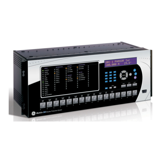
HORIZONTAL UNITS The C60 Breaker Protection System is available as a 19-inch rack horizontal mount unit with a removable faceplate. The faceplate can be specified as either standard or enhanced at the time of ordering. The enhanced faceplate contains addi- tional user-programmable pushbuttons and LED indicators. - Page 62 VERTICAL UNITS The C60 Breaker Protection System is available as a reduced size (¾) vertical mount unit, with a removable faceplate. The faceplate can be specified as either standard or enhanced at the time of ordering. The enhanced faceplate contains addi- tional user-programmable pushbuttons and LED indicators.
- Page 63 3 HARDWARE 3.1 DESCRIPTION Figure 3–4: C60 VERTICAL DIMENSIONS (ENHANCED PANEL) GE Multilin C60 Breaker Protection System...
- Page 64 3.1 DESCRIPTION 3 HARDWARE Figure 3–5: C60 VERTICAL MOUNTING AND DIMENSIONS (STANDARD PANEL) For side mounting C60 devices with the enhanced front panel, see the following documents available on the UR DVD and the GE Grid Solutions website: • GEK-113180: UR-Series UR-V Side-Mounting Front Panel Assembly Instructions •...
- Page 65 3 HARDWARE 3.1 DESCRIPTION Figure 3–6: C60 VERTICAL SIDE MOUNTING INSTALLATION (STANDARD PANEL) GE Multilin C60 Breaker Protection System...
- Page 66 3.1 DESCRIPTION 3 HARDWARE Figure 3–7: C60 VERTICAL SIDE MOUNTING REAR DIMENSIONS (STANDARD PANEL) C60 Breaker Protection System GE Multilin...
-
Page 67: Rear Terminal Layout
(nearest to CPU module) which is indicated by an arrow marker on the terminal block. See the following figure for an example of rear terminal assignments. Figure 3–9: EXAMPLE OF MODULES IN F AND H SLOTS GE Multilin C60 Breaker Protection System... - Page 68 (rows 1 to 8), use a minimum of 17 inch-pounds. During manufacturing, the power supply and CPU modules are installed in slots B and D of the chassis with 13 inch-pounds of torque on the screws at the top and bottom of the modules. C60 Breaker Protection System GE Multilin...
-
Page 69: Wiring
3 HARDWARE 3.2 WIRING 3.2WIRING 3.2.1 TYPICAL WIRING Figure 3–10: TYPICAL WIRING DIAGRAM (T MODULE SHOWN FOR CPU) GE Multilin C60 Breaker Protection System... -
Page 70: Dielectric Strength
(see the Self-test Errors section in chapter 7) or control power is lost, the relay is de-energize. For high reliability systems, the C60 has a redundant option in which two C60 power supplies are placed in parallel on the bus. -
Page 71: Ct/Vt Modules
CT connections for both ABC and ACB phase rotations are identical as shown in the Typical wiring diagram. The exact placement of a zero-sequence core balance CT to detect ground fault current is shown as follows. Twisted-pair cabling on the zero-sequence CT is recommended. GE Multilin C60 Breaker Protection System 3-11... - Page 72 Substitute the tilde “~” symbol with the slot position of the module in the following figure. NOTE Current inputs Voltage inputs 8F, 8G, 8L, and 8M modules (4 CTs and 4 VTs) Current inputs 8H, 8J, 8N, and 8R modules (8 CTs) 842766A3.CDR Figure 3–13: CT/VT MODULE WIRING 3-12 C60 Breaker Protection System GE Multilin...
-
Page 73: Process Bus Modules
3.2.5 PROCESS BUS MODULES The C60 can be ordered with a process bus interface module. This module is designed to interface with the GE Multilin HardFiber system, allowing bidirectional IEC 61850 fiber optic communications with up to eight HardFiber merging units, known as Bricks. - Page 74 Logic operand driving the contact output should be given a reset delay of 10 ms to prevent damage of the output contact (in situations when the element initiating the contact output is bouncing, at val- ues in the region of the pickup value). 3-14 C60 Breaker Protection System GE Multilin...
- Page 75 2 Inputs ~7a, ~7c 2 Inputs ~7a, ~7c 2 Inputs ~7a, ~7c 2 Inputs ~7a, ~7c 2 Inputs ~8a, ~8c 2 Inputs ~8a, ~8c 2 Inputs ~8a, ~8c 2 Inputs ~8a, ~8c 2 Inputs GE Multilin C60 Breaker Protection System 3-15...
- Page 76 Not Used ~5a, ~5c 2 Inputs 2 Outputs Solid-State Solid-State ~6a, ~6c 2 Inputs 2 Outputs Not Used Not Used ~7a, ~7c 2 Inputs 2 Outputs Solid-State Solid-State ~8a, ~8c 2 Inputs Not Used 3-16 C60 Breaker Protection System GE Multilin...
- Page 77 3 HARDWARE 3.2 WIRING Figure 3–15: CONTACT INPUT AND OUTPUT MODULE WIRING (1 of 2) GE Multilin C60 Breaker Protection System 3-17...
- Page 78 3.2 WIRING 3 HARDWARE Figure 3–16: CONTACT INPUT AND OUTPUT MODULE WIRING (2 of 2) For proper functionality, observe the polarity shown in the figures for all contact input and output con- nections. 3-18 C60 Breaker Protection System GE Multilin...
- Page 79 C60 input even when the output is open, if there is a substantial distributed capacitance (represented by C1) present in the wiring between the output and the C60 input and the debounce time setting in the C60 relay is low enough.
- Page 80 This operation of contact inputs also can be prevented by using the Auto-Burnish contact inputs or contact inputs with active impedance. Figure 3–19: CONTACT INPUT CONNECTED TO A CONTACT OUTPUT WITH RESISTOR (R2) ACROSS THE INPUT 3-20 C60 Breaker Protection System GE Multilin...
- Page 81 (EQ 3.2) The 2 mA current is used in case the contact input is connected across the GE Form A contact output with voltage monitoring. Otherwise use the amperage of the active circuit connected to the contact input when its contact output is open and the voltage across the contact input is third trigger threshold to calculate the resistor value.
- Page 82 Vresistor < contact input threshold (84 V) (EQ 3.5) In conclusion, in this example, the contact input does NOT operate falsely with the Burden Resistor across its input AND when a battery ground is present. 3-22 C60 Breaker Protection System GE Multilin...
- Page 83 CONTACT INPUT 2 AUTO-BURNISH = OFF CONTACT INPUT 1 AUTO-BURNISH = OFF CONTACT INPUT 2 AUTO-BURNISH = ON CONTACT INPUT 1 AUTO-BURNISH = ON CONTACT INPUT 2 AUTO-BURNISH = ON 842751A1.CDR Figure 3–21: AUTO-BURNISH DIP SWITCHES GE Multilin C60 Breaker Protection System 3-23...
- Page 84 Contact inputs susceptible to parasitic capacitance caused by long cable runs affected by switching surges from external circuits can result in inadvertent activation of contact inputs with the external contact open. In this case, GE recommends using the digital I/O module with active impedance circuit.
- Page 85 3 HARDWARE 3.2 WIRING Figure 3–22: ACTIVE IMPEDANCE CONTACT INPUT V-I CHARACTERISTIC GE Multilin C60 Breaker Protection System 3-25...
-
Page 86: Transducer Inputs/Outputs
(5A, 5C, 5D, 5E, and 5F) and channel arrangements that can be ordered for the relay. Wherever a tilde “~” symbol appears, substitute with the slot position of the module. NOTE Figure 3–23: TRANSDUCER INPUT/OUTPUT MODULE WIRING The following figure show how to connect RTDs. 3-26 C60 Breaker Protection System GE Multilin... -
Page 87: Rs232 Faceplate Port
3.2.8 RS232 FACEPLATE PORT A 9-pin RS232C serial port is located on the C60 faceplate for programming with a computer. All that is required to use this interface is a computer running the EnerVista UR Setup software provided with the relay. Cabling for the RS232 port is shown in the following figure for both 9-pin and 25-pin connectors. -
Page 88: Cpu Communication Ports
This common voltage is implied to be a power supply common. Some systems allow the shield (drain wire) to be used as common wire and to connect directly to the C60 COM terminal (#3); others function cor- rectly only if the common wire is connected to the C60 COM terminal, but insulated from the shield. - Page 89 The fiber optic communication ports allow for fast and efficient communications between relays at 100 Mbps. Optical fiber can be connected to the relay supporting a wavelength of 1310 nm in multi-mode. GE Multilin C60 Breaker Protection System 3-29...
-
Page 90: Irig-B
IRIG-B is a standard time code format that allows stamping of events to be synchronized among connected devices. The IRIG-B code allows time accuracies of up to 100 ns. Using the IRIG-B input, the C60 operates an internal oscillator with 1 µs resolution and accuracy. -
Page 91: Direct Input/Output Communications
Loop Timing Mode. If there is no MUX, then UR1 and UR3 can be in Internal Timing Mode and UR2 and UR4 can be in Loop Timing Mode. That is, connected channels must have opposite timing modes. Figure 3–30: RING CONFIGURATION FOR C37.94 MODULE (CONCEPT ALSO APPLIES TO G.703) GE Multilin C60 Breaker Protection System 3-31... - Page 92 Those that apply depend on options purchased. The options are outlined in the Inter-Relay Communications section of the Order Code tables in Chapter 2. All of the fiber modules use ST type connectors. 3-32 C60 Breaker Protection System GE Multilin...
-
Page 93: Fiber: Led And Eled Transmitters
The following figure shows the configuration for the 7A, 7B, 7C, 7H, 7I, and 7J fiber-only modules. Figure 3–33: LED AND ELED FIBER MODULES 3.3.3 FIBER-LASER TRANSMITTERS The following figure shows the configuration for the 72, 73, 7D, and 7K fiber-laser modules. Figure 3–34: 7X LASER FIBER MODULES GE Multilin C60 Breaker Protection System 3-33... - Page 94 Observing any fiber transmitter output can injure the eye. When using a laser Interface, attenuators can be necessary to ensure that you do not exceed the maximum optical input power to the receiver. 3-34 C60 Breaker Protection System GE Multilin...
-
Page 95: Interface
Remove the module cover screw. Remove the top cover by sliding it towards the rear and then lift it upwards. Set the timing selection switches (channel 1, channel 2) to the desired timing modes. GE Multilin C60 Breaker Protection System 3-35... - Page 96 Loop Timing Mode: The system clock is derived from the received line signal. Therefore, the G.703 timing selection should be in loop timing mode for connections to higher order systems. For connection to a higher order system (UR- 3-36 C60 Breaker Protection System GE Multilin...
- Page 97 G.703 line side of the interface while the other lies on the differential Manchester side of the interface. DMR = Differential Manchester Receiver DMX = Differential Manchester Transmitter G7X = G.703 Transmitter G7R = G.703 Receiver 842775A1.CDR Figure 3–40: G.703 DUAL LOOPBACK MODE GE Multilin C60 Breaker Protection System 3-37...
-
Page 98: Rs422 Interface
UR–RS422 channels is synchronized via the send timing leads on data module 1 as shown below. If the terminal timing feature is not available or this type of connection is not desired, the G.703 interface is a viable option that does not impose timing restrictions. 3-38 C60 Breaker Protection System GE Multilin... - Page 99 Figure 3–43: TIMING CONFIGURATION FOR RS422 TWO-CHANNEL, THREE-TERMINAL APPLICATION Data module 1 provides timing to the C60 RS422 interface via the ST(A) and ST(B) outputs. Data module 1 also provides timing to data module 2 TT(A) and TT(B) inputs via the ST(A) and AT(B) outputs. The data module pin numbers have been omitted in the figure above since they vary by manufacturer.
-
Page 100: Rs422 And Fiber Interface
G.703 and fiber interfaces. When using a laser Interface, attenuators can be necessary to ensure that you do not exceed the maximum optical input power to the receiver. Figure 3–46: G.703 AND FIBER INTERFACE CONNECTION 3-40 C60 Breaker Protection System GE Multilin... -
Page 101: Ieee C37.94 Interface
5.60. For customers using firmware release 5.60 and higher, the module can be identified with "Rev D" printed on the module and is to be used on all ends of C60 communica- tion for two and three terminal applications. - Page 102 Once the clips have cleared the raised edge of the chassis, engage the clips simultaneously. When the clips have locked into position, the module is fully inserted. 3-42 C60 Breaker Protection System GE Multilin...
- Page 103 Modules shipped since January 2012 have status LEDs that indicate the status of the DIP switches, as shown in the follow- ing figure. Figure 3–48: STATUS LEDS The clock configuration LED status is as follows: • Flashing green — loop timing mode while receiving a valid data packet GE Multilin C60 Breaker Protection System 3-43...
- Page 104 Solid yellow — FPGA is receiving a "yellow bit" and remains yellow for each "yellow bit" • Solid red — FPGA is not receiving a valid packet or the packet received is invalid 3-44 C60 Breaker Protection System GE Multilin...
-
Page 105: C37.94Sm Interface
5.60. For customers using firmware release 5.60 and higher, the module can be identified with "Rev D" printed on the module and is to be used on all ends of C60 communi- cation for two and three terminal applications. - Page 106 Once the clips have cleared the raised edge of the chassis, engage the clips simultaneously. When the clips have locked into position, the module is fully inserted. 3-46 C60 Breaker Protection System GE Multilin...
- Page 107 Modules shipped since January 2012 have status LEDs that indicate the status of the DIP switches, as shown in the follow- ing figure. Figure 3–50: STATUS LEDS The clock configuration LED status is as follows: • Flashing green — loop timing mode while receiving a valid data packet GE Multilin C60 Breaker Protection System 3-47...
- Page 108 Solid yellow — FPGA is receiving a "yellow bit" and remains yellow for each "yellow bit" • Solid red — FPGA is not receiving a valid packet or the packet received is invalid 3-48 C60 Breaker Protection System GE Multilin...
-
Page 109: Human Interfaces
The EnerVista UR Setup software is provided with every C60 relay and runs on Microsoft Windows XP, 7, and Server 2008. This chapter provides a summary of the basic EnerVista UR Setup software interface features. The EnerVista UR Setup Help File provides details for getting started and using the EnerVista UR Setup software interface. - Page 110 Site List window are automatically sent to the online communicating device. g) FIRMWARE UPGRADES The firmware of a C60 device can be upgraded, locally or remotely, via the EnerVista UR Setup software. The correspond- ing instructions are provided by the EnerVista UR Setup Help file under the topic “Upgrading Firmware”.
-
Page 111: Enervista Ur Setup Main Window
Device data view windows, with common tool bar Settings file data view windows, with common tool bar Workspace area with data view tabs Status bar 10. Quick action hot links 842786A2.CDR Figure 4–1: ENERVISTA UR SETUP SOFTWARE MAIN WINDOW GE Multilin C60 Breaker Protection System... -
Page 112: Extended Enervista Ur Setup Features
Right-click the device or file and select the Template Mode > Edit Template option to place the device in template editing mode. If prompted, enter the template password then click OK. Open the relevant settings window that contains settings to be specified as viewable. C60 Breaker Protection System GE Multilin... - Page 113 ADDING PASSWORD PROTECTION TO A TEMPLATE GE recommends that templates be saved with password protection to maximize security. When templates are created for online settings, the password is added during the initial template creation step. It does not need to be added after the template is created.
- Page 114 Template Mode > View In Template Mode command. The template specifies that only the Pickup Curve Phase time overcurrent settings window without template applied. settings be available. 842858A1.CDR Figure 4–4: APPLYING TEMPLATES VIA THE VIEW IN TEMPLATE MODE COMMAND C60 Breaker Protection System GE Multilin...
- Page 115 Once a settings template is removed, it cannot be reapplied and a new settings template needs to be defined before use. Right-click the device in the Online or Offline Window area and select the Template Mode > Remove Template option. Enter the template password and click OK to continue. GE Multilin C60 Breaker Protection System...
-
Page 116: Securing And Locking Flexlogic Equations
Select the Template Mode > View In Template Mode option to view the template. Optionally apply a password to the template by right-clicking the device and selecting the Template Mode > Pass- word Protect Template option. C60 Breaker Protection System GE Multilin... - Page 117 A serial number is viewable under Actual Values > Product Info > Model Information, the inside front panel, and the rear of the device. GE Multilin C60 Breaker Protection System...
-
Page 118: Settings File Traceability
When a settings file is transferred to a C60 device, the date, time, and serial number of the C60 are sent back to EnerVista UR Setup and added to the settings file on the local PC. This infor- mation can be compared with the C60 actual values at any later date to determine if security has been compromised. - Page 119 With respect to the above diagram, the traceability feature is used as follows. The transfer date of a setting file written to a C60 is logged in the relay and can be viewed via EnerVista UR Setup or the front panel display. Likewise, the transfer date of a setting file saved to a local PC is logged in EnerVista UR Setup.
- Page 120 ONLINE DEVICE TRACEABILITY INFORMATION The C60 serial number and file transfer date are available for an online device through the actual values. Select the Actual Values > Product Info > Model Information menu item within the EnerVista UR Setup online window as shown in the example below.
-
Page 121: Faceplate Interface
The faceplate is hinged to allow easy access to the removable modules. There is also a removable dust cover that fits over the faceplate that must be removed in order to access the keypad panel. The following figure shows the horizontal arrange- ment of the faceplate panels. Figure 4–16: UR-SERIES STANDARD HORIZONTAL FACEPLATE PANELS GE Multilin C60 Breaker Protection System 4-13... -
Page 122: Led Indicators
The status indicators in the first column are described below. • IN SERVICE: This LED indicates that control power is applied, all monitored inputs, outputs, and internal systems are OK, and that the device has been programmed. 4-14 C60 Breaker Protection System GE Multilin... - Page 123 Support for applying a customized label beside every LED is provided. Default labels are shipped in the label pack- age of every C60, together with custom templates. The default labels can be replaced by user-printed labels. User customization of LED operation is of maximum benefit in installations where languages other than English are used to communicate with operators.
- Page 124 User customization of LED operation is of maximum benefit in installations where languages other than English are used to communicate with operators. Refer to the User-programmable LEDs section in chapter 5 for the settings used to program the operation of the LEDs on these panels. 4-16 C60 Breaker Protection System GE Multilin...
-
Page 125: Custom Labeling Of Leds
4.3.3 CUSTOM LABELING OF LEDS a) ENHANCED FACEPLATE The following procedure requires these pre-requisites: • EnerVista UR Setup software is installed and operational • The C60 settings have been saved to a settings file GE Multilin C60 Breaker Protection System 4-17... - Page 126 Enter the text to appear next to each LED and above each user-programmable pushbuttons in the fields provided. Feed the C60 front panel label cutout sheet into a printer and press the Print button in the front panel report window.
- Page 127 Bend the tabs at the left end of the tool upwards as shown below. Bend the tab at the center of the tool tail as shown below. The following procedure describes how to remove the LED labels from the C60 enhanced front panel and insert the custom labels.
- Page 128 Slide the new LED label inside the pocket until the text is properly aligned with the LEDs, as shown below. The following procedure describes how to remove the user-programmable pushbutton labels from the C60 enhanced front panel and insert the custom labels.
- Page 129 Slide the label tool under the user-programmable pushbutton label until the tabs snap out as shown below. This attaches the label tool to the user-programmable pushbutton label. Remove the tool and attached user-programmable pushbutton label as shown below. GE Multilin C60 Breaker Protection System 4-21...
-
Page 130: Display
INTRODUCTION The C60 can interface with associated circuit breakers. In many cases the application monitors the state of the breaker, that can be presented on faceplate LEDs, along with a breaker trouble indication. Breaker operations can be manually initiated from faceplate keypad or automatically initiated from a FlexLogic operand. -
Page 131: Menus
Press the MENU key to select a header display page (top-level menu). The header title appears momentarily followed by a header display page menu item. Each press of the MENU key advances through the following main heading pages: • Actual values • Settings GE Multilin C60 Breaker Protection System 4-23... - Page 132 4.3 FACEPLATE INTERFACE 4 HUMAN INTERFACES • Commands • Targets • User displays (when enabled) 4-24 C60 Breaker Protection System GE Multilin...
- Page 133 Pressing the MESSAGE DOWN key displays the second setting sub-header associ- PROPERTIES ated with the Product Setup header. Press the MESSAGE RIGHT key once more to display the first setting for Display FLASH MESSAGE Properties. TIME: 1.0 s GE Multilin C60 Breaker Protection System 4-25...
-
Page 134: Changing Settings
ENTERING ALPHANUMERIC TEXT Text settings have data values which are fixed in length, but user-defined in character. They can be upper case letters, lower case letters, numerals, and a selection of special characters. 4-26 C60 Breaker Protection System GE Multilin... -
Page 135: Settings
The information in this section refers to password security. For information on how to set or change CyberSentry pass- words, see the Settings > Product Setup > Security > CyberSentry section in the next chapter. GE Multilin C60 Breaker Protection System 4-27... - Page 136 By default, when an incorrect Command or Setting password has been entered via the faceplate interface three times within three minutes, the FlexLogic operand is set to “On” and the C60 does not allow settings or LOCAL ACCESS DENIED command level access via the faceplate interface for the next five minutes.
-
Page 137: Overview
See page 5-91. TELEPROTECTION See page 5-99. INSTALLATION See page 5-100. SETTINGS AC INPUTS See page 5-102. SYSTEM SETUP POWER SYSTEM See page 5-104. GE Multilin C60 Breaker Protection System... - Page 138 SYNCHROCHECK See page 5-215. AUTORECLOSE See page 5-220. DIGITAL ELEMENTS See page 5-233. DIGITAL COUNTERS See page 5-236. MONITORING See page 5-238. ELEMENTS C60 Breaker Protection System GE Multilin...
- Page 139 TRANSDUCER I/O RTD INPUTS See page 5-274. DCMA OUTPUTS See page 5-276. SETTINGS TEST MODE See page 5-279. TESTING FUNCTION: Disabled TEST MODE FORCING: See page 5-279. GE Multilin C60 Breaker Protection System...
-
Page 140: Introduction To Elements
For wye-connected VTs, the primary and secondary bases quanitities are as before, but the secondary voltage (here a phase-to-phase ground value) is: 13800 --------------- - × --------- - 66.4 V (EQ 5.2) 14400 Many settings are common to most elements and are discussed below: C60 Breaker Protection System GE Multilin... -
Page 141: Introduction To Ac Sources
The same considerations apply to transformer winding 2. The protection elements require access to the net current for transformer protection, but some elements may need access to the individual currents from CT1 and CT2. GE Multilin C60 Breaker Protection System... - Page 142 INCREASING SLOT POSITION LETTER --> CT/VT MODULE 1 CT/VT MODULE 2 CT/VT MODULE 3 < bank 1 > < bank 3 > < bank 5 > < bank 2 > < bank 4 > < bank 6 > C60 Breaker Protection System GE Multilin...
- Page 143 Upon startup, the CPU configures the settings required to characterize the current and voltage inputs, and will display them in the appropriate section in the sequence of the banks (as described above) as follows for a maximum configuration: F1, F5, M1, M5, U1, and U5. GE Multilin C60 Breaker Protection System...
-
Page 144: Product Setup
To reset the unit after a lost password: Email GE customer service at multilin.tech@ge.com with the serial number and using a recognizable corporate email account. Customer service provides a code to reset the relay to the factory defaults. - Page 145 When entering a settings or command password via EnerVista or any serial interface, the user must enter the correspond- ing connection password. If the connection is to the back of the C60, the remote password must be used. If the connection is to the RS232 port of the faceplate, the local password must be used.
- Page 146 INVALID ATTEMPTS BEFORE LOCKOUT The C60 provides a means to raise an alarm upon failed password entry. Should password verification fail while accessing a password-protected level of the relay (either settings or commands), the FlexLogic operand is UNAUTHORIZED ACCESS asserted.
- Page 147 When this occurs, local access is permitted and the timer pro- grammed with the setting value is started. When this timer expires, local setting access is ACCESS AUTH TIMEOUT GE Multilin C60 Breaker Protection System 5-11...
- Page 148 It is disabled by default to allow the administrator direct access to the EnerVista software immediately after installation. When security is disabled, all users have administrator access. GE recommends enabling the EnerVista security before placing the device in service.
- Page 149 Enter a username in the User field. The username must be 4 to 20 characters in length. Select the user access rights by enabling the check box of one or more of the fields. GE Multilin C60 Breaker Protection System 5-13...
- Page 150 Deletes the user account when exiting the user management window Actual Values Allows the user to read actual values Settings Allows the user to read setting values Commands Allows the user to execute commands 5-14 C60 Breaker Protection System GE Multilin...
- Page 151 Note that other protocols (DNP, 101, 103, 104, EGD) are not encrypted, and they are good communications options for SCADA systems when CyberSentry is enabled. CYBERSENTRY SETTINGS THROUGH ENERVISTA CyberSentry security settings are configured under Device > Settings > Product Setup > Security. GE Multilin C60 Breaker Protection System 5-15...
- Page 152 Authentication method used by RADIUS EAP-TTLS EAP-TTLS EAP-TTLS Administrator Authentication server. Currently fixed to EAP-TTLS. Method Timeout Timeout in seconds between re- 9999 Administrator transmission requests Retries Number of retries before giving up 9999 Administrator 5-16 C60 Breaker Protection System GE Multilin...
- Page 153 See the Change Text The specified role password-protected. All RADIUS users are Password following Me1# and Administrator, password-protected. Requirement password except for s section section for Supervisor, where requireme it is only itself GE Multilin C60 Breaker Protection System 5-17...
-
Page 154: Security
This role can also be disabled, but only through a Supervisor authentication. When this role is disabled its permissions are assigned to the Administrator role. 5-18 C60 Breaker Protection System GE Multilin... - Page 155 LOAD FACTORY DEFAULTS: This setting is used to reset all the settings, communication and security passwords. An Administrator role is used to change this setting and a Supervisor role (if not disabled) approves it. GE Multilin C60 Breaker Protection System 5-19...
- Page 156 Administrator if the Supervisor role is disabled. The Supervisor role enables this setting for the relay to start accepting setting changes or command changes or firmware upgrade. After all the setting changes are applied or com- mands executed, the Supervisor disables to lock setting changes. 5-20 C60 Breaker Protection System GE Multilin...
- Page 157 Observer). When using a serial connection, only device authentication is supported. When server authentication is required, characteristics for communication with a RADIUS server must be configured. This is possible only in the EnerV- GE Multilin C60 Breaker Protection System 5-21...
- Page 158 Event Number — Event identification number (index) Date & Timestamp — UTC date and time Username — 255 chars maximum, but in the security log it is truncated to 20 characters IP address — Device IP address 5-22 C60 Breaker Protection System GE Multilin...
- Page 159 Notice (5) Clear energy command was issued RESET_UNAUTH_ACCESS Warning (4) Reset Unauthorized access command was issued CLEAR_TELEPROTECTION_CNT Notice (5) Clear teleprotection counters command was issued CLEAR_ALL_RECS Warning (4) Clear all records command was issued GE Multilin C60 Breaker Protection System 5-23...
-
Page 160: Display Properties
Some customers prefer very low currents to display as zero, while others prefer the current be displayed even when the value reflects noise rather than the actual signal. The C60 applies a cut- off value to the magnitudes and angles of the measured currents. -
Page 161: Clear Relay Records
CLEAR EVENT RECORDS: MESSAGE Range: FlexLogic operand CLEAR OSCILLOGRAPHY? MESSAGE Range: FlexLogic operand CLEAR DATA LOGGER: MESSAGE Range: FlexLogic operand CLEAR ARC AMPS 1: MESSAGE Range: FlexLogic operand CLEAR ARC AMPS 2: MESSAGE GE Multilin C60 Breaker Protection System 5-25... - Page 162 Selected records can be cleared from user-programmable conditions with FlexLogic operands. Assigning user-programma- ble pushbuttons to clear specific records are typical applications for these commands. Since the C60 responds to rising edges of the configured FlexLogic operands, they must be asserted for at least 50 ms to take effect.
-
Page 163: Communications
MESSAGE MIN TIME: 0 ms : The C60 is equipped with two independent serial communication ports. The faceplate RS485 COM2 BAUD RATE PARITY RS232 port is intended for local use and is fixed at 19200 bit/s baud and even parity. The rear COM2 port is RS485 and has settings for baud rate and parity. - Page 164 ETHERNET NETWORK TOPOLOGY The C60 has three Ethernet ports. Each Ethernet port must belong to a different network or subnetwork. Configure the IP address and subnet to ensure that each port meets this requirement. Two subnets are different when the bitwise AND oper- ation performed between their respective IP address and mask produces a different result.
- Page 165 LAN3, to which port 3 (P3) is connected. There is no redundancy. Figure 5–6: MULTIPLE LANS, NO REDUNDANCY Public Network SCADA EnerVista Software LAN1 LAN2 LAN3 ML3000 ML3000 ML3000 IP1/ IP2/ IP3/ MAC2 MAC3 MAC1 859710A2.vsd GE Multilin C60 Breaker Protection System 5-29...
- Page 166 IP addresses and mask. Configure the network IP and subnet settings before configuring the rout- ing settings. To obtain a list of all port numbers used, for example for audit purposes, contact GE technical support with substantiating information, such as the serial number and order code of your device.
- Page 167 2 is performed. The delay in switching back ensures that rebooted switching devices connected to the C60, which signal their ports as active prior to being completely functional, have time to completely initialize themselves and become active. Once port 2 is active again, port 3 returns to standby mode.
- Page 168 The default route is used as the last choice when no other route towards a given destination is found. Range: Standard IPV4 unicast address format IPV4 DEFAULT ROUTE GATEWAY ADDRESS 127.0.0.1 5-32 C60 Breaker Protection System GE Multilin...
- Page 169 (RtGwy & Prt1Mask) == (Prt1IP & Prt1Mask) || (RtGwy & Prt2Mask) == (Prt2IP & Prt2Mask) || (RtGwy & Prt3Mask) == (Prt3IP & Prt3Mask) where & is the bitwise-AND operator == is the equality operator || is the logical OR operator GE Multilin C60 Breaker Protection System 5-33...
- Page 170 PRT2 IP ADDRESS = 10.1.2.2 PRT2 SUBNET IP MASK = 255.255.255.0 IPV4 DEFAULT ROUTE: GATEWAY ADDRESS = 10.1.1.1 STATIC NETWORK ROUTE 1: RT1 DESTINATION = 10.1.3.0/24; RT1 NET MASK = 255.255.255.0; and RT1 GATE- WAY = 10.1.2.1 5-34 C60 Breaker Protection System GE Multilin...
- Page 171 This allows the EnerVista UR Setup software to be used on the port. The UR operates as a Modbus slave device only. When using Modbus protocol on the RS232 port, the C60 responds regardless of the pro- MODBUS SLAVE ADDRESS grammed.
- Page 172 Modbus, IEC 61850 Channel 2: RS485 Channel 1: RS485 Modbus Modbus, IEC 61850 Channel 2: none IEC 104 Modbus Modbus IEC 104, Modbus, IEC 61850 IEC 103 Modbus IEC 103 Modbus, IEC 61850 5-36 C60 Breaker Protection System GE Multilin...
- Page 173 DEADBAND: 30000 Range: 0 to 100000000 in steps of 1 DNP OTHER DEFAULT MESSAGE DEADBAND: 30000 Range: 1 to 10080 min. in steps of 1 DNP TIME SYNC IIN MESSAGE PERIOD: 1440 min GE Multilin C60 Breaker Protection System 5-37...
- Page 174 PROTOCOL nected to multiple DNP masters (usually an RTU or a SCADA master station). Since the C60 maintains two sets of DNP data change buffers and connection information, two DNP masters can actively communicate with the C60 at one time.
- Page 175 DNP analog input points that are voltages will be returned with values 1000 times smaller (for example, a value of 72000 V on the C60 will be returned as 72). These settings are useful when analog input values must be adjusted to fit within cer- tain ranges in DNP masters.
- Page 176 (for circuit breakers) or raise/lower (for tap changers) using a single control point. That is, the DNP master can operate a single point for both trip and close, or raise and lower, operations. The C60 can be configured to sup- port paired control points, with each paired control point operating two virtual inputs.
- Page 177 The C60 supports the Manufacturing Message Specification (MMS) protocol as specified by IEC 61850. MMS is supported over two protocol stacks: TCP/IP over Ethernet. The C60 operates as an IEC 61850 server. The Remote Inputs and Out- puts section in this chapter describe the peer-to-peer GSSE/GOOSE message scheme.
- Page 178 IEC 61850 GSSE application ID name string sent as part of each GSSE message. This GSSE ID string identifies the GSSE message to the receiving device. In C60 releases previous to 5.0x, this name string was repre- sented by the setting.
- Page 179 DESTINATION MAC address; the least significant bit of the first byte must be set. In C60 releases previous to 5.0x, the destination Ethernet MAC address was determined automatically by taking the sending MAC address (that is, the unique, local MAC address of the C60) and setting the multicast bit.
- Page 180 The C60 has the ability of detecting if a data item in one of the GOOSE datasets is erroneously oscillating. This can be caused by events such as errors in logic programming, inputs improperly being asserted and de-asserted, or failed station components.
- Page 181 Configure the transmission dataset. Configure the GOOSE service settings. Configure the data. The general steps required for reception configuration are: Configure the reception dataset. Configure the GOOSE service settings. Configure the data. GE Multilin C60 Breaker Protection System 5-45...
- Page 182 MMXU1 HZ DEADBAND change greater than 45 mHz, from the previous MMXU1.MX.mag.f value, in the source frequency. The C60 must be rebooted (control power removed and re-applied) before these settings take effect. The following procedure illustrates the reception configuration. Configure the reception dataset by making the following changes in the ...
- Page 183 IEC61850 GOOSE ANALOG INPUT 1 UNITS The GOOSE analog input 1 can now be used as a FlexAnalog value in a FlexElement or in other settings. The C60 must be rebooted (control power removed and re-applied) before these settings take effect.
- Page 184 DNA and UserSt bit pairs that are included in GSSE messages. To set up a C60 to receive a configurable GOOSE dataset that contains two IEC 61850 single point status indications, the following dataset items can be selected (for example, for configurable GOOSE dataset 1): “GGIO3.ST.Ind1.stVal” and “GGIO3.ST.Ind2.stVal”.
- Page 185 CPU resources. When server scanning is disabled, there is no updating of the IEC 61850 logical node status values in the C60. Clients are still able to connect to the server (C60 relay), but most data values are not updated. This set- ting does not affect GOOSE/GSSE operation.
- Page 186 (_) character, and the first character in the prefix must be a letter. This conforms to the IEC 61850 standard. Changes to the logical node prefixes will not take effect until the C60 is restarted. The main menu for the IEC 61850 MMXU deadbands is shown below.
- Page 187 The GGIO2 control configuration settings are used to set the control model for each input. The available choices are “0” (status only), “1” (direct control), and “2” (SBO with normal security). The GGIO2 control points are used to control the C60 virtual inputs.
- Page 188 GGIO1 (binary status values). The settings allow the selection of FlexInteger values for each GGIO5 integer value point. It is intended that clients use GGIO5 to access generic integer values from the C60. Additional settings are provided to allow the selection of the number of integer values available in GGIO5 (1 to 16), and to assign FlexInteger values to the GGIO5 integer inputs.
- Page 189 ITEM 64 attributes supported by the C60. Changes to the dataset will only take effect when the C60 is restarted. It is recommended to use reporting service from logical node LLN0 if a user needs some (but not all) data from already existing GGIO1, GGIO4, and MMXU4 points and their quantity is not greater than 64 minus the number items in this dataset.
- Page 190 XCBR operating counter status attribute (OpCnt) increments with every operation. Frequent breaker operation can result in very large OpCnt values over time. This setting allows the OpCnt to be reset to “0” for XCBR1. 5-54 C60 Breaker Protection System GE Multilin...
- Page 191 Since GSSE/GOOSE messages are multicast Ethernet by specification, they are not usually be forwarded by net- work routers. However, GOOSE messages may be forwarded by routers if the router has been configured for VLAN functionality. NOTE GE Multilin C60 Breaker Protection System 5-55...
- Page 192 Menu”. Web pages are available showing DNP and IEC 60870-5-104 points lists, Modbus registers, event records, fault reports, and so on. First connect the UR and a computer to an Ethernet network, then enter the IP address of the C60 Ethernet port employed into the “Address”...
- Page 193 PROTOCOL connected to a maximum of two masters (usually either an RTU or a SCADA master station). Since the C60 maintains two sets of IEC 60870-5-104 data change buffers, no more than two masters should actively communicate with the C60 at one time.
- Page 194 MESSAGE 0.0.0.0 The C60 can specify a maximum of five clients for its IEC 104 connections. These are IP addresses for the controllers to which the C60 can connect. A maximum of two simultaneous connections are supported at any given time.
- Page 195 MESSAGE (Modbus register address range) Fast exchanges (50 to 1000 ms) are generally used in control schemes. The C60 has one fast exchange (exchange 1) and two slow exchanges (exchange 2 and 3). The settings menu for the slow EGD exchanges is shown below: ...
- Page 196 SNTP, its time is overwritten by these three sources, if any of them is active. If the synchronization timeout occurs and none of IRIG-B, PTP, or SNTP is active, the C60 sets the invalid bit in the time stamp of a time-tagged message.
- Page 197 Spontaneous transmission occurs as a response to cyclic Class 2 requests. If the C60 wants to transmit Class 1 data at that time, it demands access for Class 1 data transmission (ACD=1 in the con- trol field of the response).
- Page 198 ASDU 4 ANALOG 9 MESSAGE Range: 0.000 to 65.535 in steps of 0.001 ASDU 4 ANALOG 9 MESSAGE FACTOR: 1.000 Range: -32768 to 32767 in steps of 1 ASDU 4 ANALOG 9 MESSAGE OFFSET: 0 5-62 C60 Breaker Protection System GE Multilin...
- Page 199 FlexAnalog operands. The measurands sent are voltage, current, power, power fac- tor, and frequency. If any other FlexAnalog is chosen, the C60 sends 0 instead of its value. Note that the power is transmit- ted in KW, not W.
- Page 200 ASDU command comes. A list of available mappings is provided on the C60. This includes 64 virtual inputs (see the following table). The ON and OFF for the same ASDU command can be mapped to different virtual inputs.
-
Page 201: Modbus User Map
±1 minute per month (~23 ppm). Once the RTC is synchronized with the Precision Time Protocol (PTP), IRIG-B, or SNTP, its accuracy approaches that of the synchroniz- GE Multilin C60 Breaker Protection System 5-65... - Page 202 PROTOCOL (1588) Disabled Range: 0 to 255 PTP DOMAIN NUMBER MESSAGE Range: 0 to 7 PTP VLAN PRIORITY MESSAGE Range: 0 to 4095 PTP VLAN ID MESSAGE PTP PORT 1 MESSAGE 5-66 C60 Breaker Protection System GE Multilin...
- Page 203 Should a clock on starting up discover it is “better” that the present grandmaster, it assumes the grandmaster role and the previous grandmaster reverts to slave. The C60 qualification mechanism accepts a potential master clock as a new grandmaster, when in a four-second interval it has received three announce messages from it, all better than the present grandmaster clock and better than any other announce in this interval.
- Page 204 Ethernet switch it is connected to is 9 000 ns and the that the delay from the switch to the relay is 11 000 ns, then the mean delay is 10 000 ns, and the path delay asymmetry is 11000 - 10000 = +1000 ns. 5-68 C60 Breaker Protection System GE Multilin...
- Page 205 C60 clock is closely synchronized with the SNTP/NTP server. It takes up to two minutes for the C60 to signal an SNTP self-test error if the server is offline.
-
Page 206: Fault Reports
MESSAGE Z0 ANGLE: 75° The C60 relay supports one fault report and an associated fault locator. The signal source and trigger condition, as well as the characteristics of the line or feeder, are entered in this menu. The fault report stores data, in non-volatile memory, pertinent to an event when triggered. The captured data contained in the FaultReport.txt file includes:... - Page 207 “I0”. The magnitude is to be entered in secondary ohms. This impedance is an average system equivalent behind the relay. It can be calculated as zero-sequence Thevenin impedance at the local bus with the protected line/feeder GE Multilin C60 Breaker Protection System 5-71...
-
Page 208: Oscillography
25% consists of 25% pre- and 75% post-trigger data. The is always captured in oscillography and TRIGGER SOURCE can be any FlexLogic parameter (element state, contact input, virtual output, and so on). The relay sampling rate is 64 sam- ples per cycle. 5-72 C60 Breaker Protection System GE Multilin... - Page 209 All eight CT/VT module channels are stored in the oscillography file. The CT/VT module channels are named as follows: <slot_letter><terminal_number>—<I or V><phase A, B, or C, or 4th input> GE Multilin C60 Breaker Protection System 5-73...
-
Page 210: Data Logger
The relay automatically partitions the available memory between the channels in use. Exam- ple storage capacities for a system frequency of 60 Hz are shown in the following table. 5-74 C60 Breaker Protection System GE Multilin... - Page 211 – entering this number via the relay keypad will cause the corresponding parameter to be displayed. • DATA LOGGER CONFIG: This display presents the total amount of time the Data Logger can record the channels not selected to “Off” without over-writing old data. GE Multilin C60 Breaker Protection System 5-75...
-
Page 212: Demand
Start Demand Interval logic input pulses. Each new value of demand becomes available at the end of each pulse. Assign a FlexLogic operand to the setting to program the input for the new DEMAND TRIGGER demand interval pulses. 5-76 C60 Breaker Protection System GE Multilin... -
Page 213: User-Programmable Leds
LEDs. This test checks for hardware failures that lead to more than one LED being turned off from a single logic point. This stage can be interrupted at any time. GE Multilin C60 Breaker Protection System 5-77... - Page 214 LEDs are being visually inspected. When finished, the pushbutton should be released. The relay will then automatically start stage 2. At this point forward, test may be aborted by pressing the pushbutton. 5-78 C60 Breaker Protection System GE Multilin...
- Page 215 “Latched”, the LED, once lit, remains so until reset by the faceplate RESET button, from a remote device via a communica- tions channel, or from any programmed operand, even if the LED operand state de-asserts. GE Multilin C60 Breaker Protection System 5-79...
-
Page 216: User-Programmable Self Tests
Range: Disabled, Enabled. SFP MODULE FAIL MESSAGE FUNCTION: Disabled All major self-test alarms are reported automatically with their corresponding FlexLogic operands, events, and targets. Most of the minor alarms can be disabled if desired. 5-80 C60 Breaker Protection System GE Multilin... - Page 217 ANY MINOR ALARM ANY SELF-TEST minor alarms continue to function along with other major and minor alarms. See the Relay Self-tests section in chapter 7 for information on major and minor self-test alarms. GE Multilin C60 Breaker Protection System 5-81...
-
Page 218: Control Pushbuttons
The location of the control pushbuttons are shown in the following figures. Control pushbuttons 842813A1.CDR Figure 5–11: CONTROL PUSHBUTTONS (ENHANCED FACEPLATE) An additional four control pushbuttons are included on the standard faceplate when the C60 is ordered with the 12 user- programmable pushbutton option. STATUS EVENT CAUSE... - Page 219 SYSTEM SETUP/ BREAKERS/BREAKER 1/ BREAKER 1 PUSHBUTTON CONTROL Enabled=1 TIMER FLEXLOGIC OPERAND SYSTEM SETUP/ BREAKERS/BREAKER 2/ CONTROL PUSHBTN 1 ON 100 msec BREAKER 2 PUSHBUTTON CONTROL 842010A2.CDR Enabled=1 Figure 5–13: CONTROL PUSHBUTTON LOGIC GE Multilin C60 Breaker Protection System 5-83...
- Page 220 MESSAGE EVENTS: Disabled The C60 is provided with this optional feature, specified as an option at the time of ordering. Using the order code for your device, see the order codes in chapter 2 for details. User-programmable pushbuttons provide an easy and error-free method of entering digital state (on, off) information. The number depends on the front panel ordered.
- Page 221 FlexLogic, the pulse duration is specified by the only. The time the operand remains PUSHBTN 1 DROP-OUT TIME assigned to the setting remains On has no effect on the pulse duration. PUSHBTN 1 SET GE Multilin C60 Breaker Protection System 5-85...
- Page 222 PUSHBTN 1 LED CTL: This setting assigns the FlexLogic operand serving to drive the front panel pushbutton LED. If this setting is “Off”, then LED operation is directly linked to the operand. PUSHBUTTON 1 ON 5-86 C60 Breaker Protection System GE Multilin...
- Page 223 PUSHBUTTON 1 EVENTS: If this setting is enabled, each user-programmable pushbutton state change is logged as an event into the event recorder. The figures show the user-programmable pushbutton logic. Figure 5–16: USER-PROGRAMMABLE PUSHBUTTON LOGIC (Sheet 1 of 2) GE Multilin C60 Breaker Protection System 5-87...
- Page 224 PATH: SETTINGS PRODUCT SETUP FLEX STATE PARAMETERS Range: FlexLogic operand FLEX STATE PARAMETER PARAMETERS Range: FlexLogic operand PARAMETER MESSAGE Range: FlexLogic operand PARAMETER MESSAGE ↓ Range: FlexLogic operand PARAMETER 256: MESSAGE 5-88 C60 Breaker Protection System GE Multilin...
- Page 225 INVOKE AND SCROLL play, not at the first user-defined display. The pulses must last for at least 250 ms to take effect. INVOKE AND SCROLL GE Multilin C60 Breaker Protection System 5-89...
- Page 226 While viewing a user display, press the ENTER key and then select the ‘Yes” option to remove the display from the user display list. Use the MENU key again to exit the user displays menu. 5-90 C60 Breaker Protection System GE Multilin...
-
Page 227: Direct Inputs And Outputs
See page 5–97. CRC ALARM CH2 MESSAGE See page 5–97. UNRETURNED MESSAGE See page 5–98. MESSAGES ALARM CH1 UNRETURNED MESSAGE See page 5–98. MESSAGES ALARM CH2 GE Multilin C60 Breaker Protection System 5-91... - Page 228 Delivery time for direct input and output messages is approximately 0.2 of a power system cycle at 128 kbps and 0.4 of a power system cycle at 64 kbps, per each ‘bridge’. 5-92 C60 Breaker Protection System GE Multilin...
- Page 229 The following application examples illustrate the basic concepts for direct input and output configuration. See the Inputs and Outputs section in this chapter for information on configuring FlexLogic operands (flags, bits) to be exchanged. GE Multilin C60 Breaker Protection System 5-93...
- Page 230 UR IED 1 BLOCK UR IED 4 UR IED 2 UR IED 3 842712A1.CDR Figure 5–19: SAMPLE INTERLOCKING BUSBAR PROTECTION SCHEME For increased reliability, a dual-ring configuration (shown below) is recommended for this application. 5-94 C60 Breaker Protection System GE Multilin...
- Page 231 The complete application requires addressing a number of issues such as failure of both the communications rings, failure or out-of-service conditions of one of the relays, etc. Self-monitoring flags of the direct inputs and outputs feature would be primarily used to address these concerns. GE Multilin C60 Breaker Protection System 5-95...
- Page 232 Inputs and Outputs section. A blocking pilot-aided scheme should be implemented with more security and, ideally, faster message delivery time. This is accomplished using a dual-ring configuration as shown here. 5-96 C60 Breaker Protection System GE Multilin...
- Page 233 EVENTS: Disabled The C60 checks integrity of the incoming direct input and output messages using a 32-bit CRC. The CRC alarm function is available for monitoring the communication medium noise by tracking the rate of messages failing the CRC check. The monitoring function counts all incoming messages, including messages that failed the CRC check.
- Page 234 MESSAGE EVENTS: Disabled The C60 checks integrity of the direct input and output communication ring by counting unreturned messages. In the ring configuration, all messages originating at a given device should return within a pre-defined period of time. The unreturned messages alarm function is available for monitoring the integrity of the communication ring by tracking the rate of unre- turned messages.
- Page 235 On two- terminals two-channel systems, the same is transmitted over LOCAL RELAY ID NUMBER both channels; as such, only the has to be programmed on the receiving end. TERMINAL 1 ID NUMBER GE Multilin C60 Breaker Protection System 5-99...
-
Page 236: Installation
"Programmed" state. UNIT NOT PROGRAMMED setting allows the user to uniquely identify a relay. This name will appear on generated reports. RELAY NAME 5-100 C60 Breaker Protection System GE Multilin... -
Page 237: Remote Resources Configuration
Bricks. Remote resources settings configure the point-to-point connection between specific fiber optic ports on the C60 process card and specific Brick. The relay is then configured to measure spe- cific currents, voltages and contact inputs from those Bricks, and to control specific outputs. - Page 238 1000:1 CT before summation. If a protection element is set up to act on SRC 1 currents, then a pickup level of 1 pu will operate on 1000 A primary. The same rule applies for current sums from CTs with different secondary taps (5 A and 1 A). 5-102 C60 Breaker Protection System GE Multilin...
- Page 239 = 66.4. On a 14.4 kV system with a delta connection and a VT primary to secondary turns ratio of 14400:120, the voltage value entered would be 120; that is, 14400 / 120. GE Multilin C60 Breaker Protection System 5-103...
-
Page 240: System Setup
“Disabled” only in unusual circumstances; consult the factory for special variable- FREQUENCY TRACKING frequency applications. NOTE The frequency tracking feature functions only when the C60 is in the “Programmed” mode. If the C60 is “Not Pro- grammed”, then metering values are available but can exhibit significant errors. NOTE 5-104... -
Page 241: Signal Sources
CT wiring problem. A disturbance detector is provided for each source. The 50DD function responds to the changes in magnitude of the sequence currents. The disturbance detector scheme logic is as follows: GE Multilin C60 Breaker Protection System 5-105... - Page 242 This configuration could be used on a two-winding transformer, with one winding connected into a breaker-and-a-half sys- tem. The following figure shows the arrangement of sources used to provide the functions required in this application, and the CT/VT inputs that are used to provide the data. 5-106 C60 Breaker Protection System GE Multilin...
- Page 243 5.4 SYSTEM SETUP Figure 5–26: EXAMPLE USE OF SOURCES Y LV D HV SRC 1 SRC 2 SRC 3 Phase CT F1+F5 None Ground CT None None Phase VT None None Aux VT None None GE Multilin C60 Breaker Protection System 5-107...
-
Page 244: Breakers
Range: 0.000 to 65.535 s in steps of 0.001 MANUAL CLOSE RECAL1 MESSAGE TIME: 0.000 s Range: FlexLogic operand BREAKER 1 OUT OF SV: MESSAGE Range: Disabled, Enabled BREAKER 1 EVENTS: MESSAGE Disabled 5-108 C60 Breaker Protection System GE Multilin... - Page 245 1. The number of breaker control elements is dependent on the number of CT/VT modules specified with the C60. The follow- ing settings are available for each breaker control element.
- Page 246 5.4 SYSTEM SETUP 5 SETTINGS Figure 5–27: DUAL BREAKER CONTROL SCHEME LOGIC (Sheet 1 of 2) IEC 61850 functionality is permitted when the C60 is in “Programmed” mode and not in the local control mode. NOTE 5-110 C60 Breaker Protection System...
- Page 247 Note that IEC 61850 commands are event-driven and dwell time for these is one protection pass only. If you want to main- tain the close/open command for a certain time, do so either on the contact outputs using the "Seal-in" setting or in Flex- Logic. GE Multilin C60 Breaker Protection System 5-111...
-
Page 248: Disconnect Switches
SWITCH 1 FUNCTION: This setting enables and disables the operation of the disconnect switch element. • SWITCH 1 NAME: Assign a user-defined name (up to six characters) to the disconnect switch. This name will be used in flash messages related to disconnect switch 1. 5-112 C60 Breaker Protection System GE Multilin... - Page 249 This allows for non-simultaneous operation of the poles. IEC 61850 functionality is permitted when the C60 is in “Programmed” mode and not in the local control mode. NOTE GE Multilin...
- Page 250 5.4 SYSTEM SETUP 5 SETTINGS Figure 5–29: DISCONNECT SWITCH SCHEME LOGIC 5-114 C60 Breaker Protection System GE Multilin...
-
Page 251: Flexcurves
0.86 15.0 0.48 0.88 15.5 0.50 0.90 16.0 0.52 0.91 16.5 0.54 0.92 17.0 0.56 0.93 17.5 0.58 0.94 18.0 0.60 0.95 18.5 0.62 0.96 19.0 0.64 0.97 19.5 0.66 0.98 10.0 20.0 GE Multilin C60 Breaker Protection System 5-115... - Page 252 The multiplier and adder settings only affect the curve portion of the characteristic and not the MRT and HCT set- tings. The HCT settings override the MRT settings for multiples of pickup greater than the HCT ratio. NOTE 5-116 C60 Breaker Protection System GE Multilin...
- Page 253 EnerVista UR Setup software generates an error message and discards the proposed changes. NOTE e) STANDARD RECLOSER CURVES The standard recloser curves available for the C60 are displayed in the following graphs. GE Multilin C60 Breaker Protection System...
- Page 254 CURRENT (multiple of pickup) 842723A1.CDR Figure 5–33: RECLOSER CURVES GE101 TO GE106 GE142 GE138 GE120 GE113 0.05 7 8 9 10 12 CURRENT (multiple of pickup) 842725A1.CDR Figure 5–34: RECLOSER CURVES GE113, GE120, GE138 AND GE142 5-118 C60 Breaker Protection System GE Multilin...
- Page 255 Figure 5–35: RECLOSER CURVES GE134, GE137, GE140, GE151 AND GE201 GE152 GE141 GE131 GE200 7 8 9 10 12 CURRENT (multiple of pickup) 842728A1.CDR Figure 5–36: RECLOSER CURVES GE131, GE141, GE152, AND GE200 GE Multilin C60 Breaker Protection System 5-119...
- Page 256 Figure 5–37: RECLOSER CURVES GE133, GE161, GE162, GE163, GE164 AND GE165 GE132 GE139 GE136 GE116 0.05 GE117 GE118 0.02 0.01 7 8 9 10 12 CURRENT (multiple of pickup) 842726A1.CDR Figure 5–38: RECLOSER CURVES GE116, GE117, GE118, GE132, GE136, AND GE139 5-120 C60 Breaker Protection System GE Multilin...
- Page 257 Figure 5–39: RECLOSER CURVES GE107, GE111, GE112, GE114, GE115, GE121, AND GE122 GE202 GE135 GE119 7 8 9 10 12 CURRENT (multiple of pickup) 842727A1.CDR Figure 5–40: RECLOSER CURVES GE119, GE135, AND GE202 GE Multilin C60 Breaker Protection System 5-121...
-
Page 258: Phasor Measurement Unit
See page 5–143. CONFIGURATION The C60 is provided with an optional phasor measurement unit feature. This feature is specified as a soft- ware option at the time of ordering. The number of phasor measurement units available can also depend on this option. - Page 259 Precise time input to the relay from the international time standard, via either IRIG-B or PTP, is vital for correct syn- chrophasor measurement and reporting. For IRIG-B, a DC level shift IRIG-B receiver must be used for the phasor measurement unit to output proper synchrophasor values. NOTE GE Multilin C60 Breaker Protection System 5-123...
- Page 260 16 character name field provided within the Basic Configuration menu. Additionally, the names of the 16 binary points are implemented as numbered descriptions — d1, d2, d3, and so on. The number of descriptions are equal to the number of bits configured in the 16 bit digital status word. 5-124 C60 Breaker Protection System GE Multilin...
- Page 261 From each PMU, the user selects the phasor information of interest that is mapped into the selected aggregator datset(s). For version 7.0 and later only FCDA data is supported. Figure 5–44: DATA SET CREATED FROM USER SELECTED INTERNAL ITEMS GE Multilin C60 Breaker Protection System 5-125...
- Page 262 CONFIGURATION EXAMPLE: CFG-2 based configuration (using IEC 61850-90-5) The C60 is expected to send the CFG-2 file (IEEE C37.118 config. file) upon request from the upstream synchrophasor devices (for example, P30) without stopping R-SV multicasting, as shown in the figure below. The primary domain control- ler (PDC) does not need to use a stop/start data stream command if the UR protocol is set to IEC 61850-90-5 prior to requesting the configuration via CFG-2 (IEEE C37.118 config.
- Page 263 See page 5-128. UNIT 1 CONFIGURATION PMU 1 MESSAGE See page 5-132. CALIBRATION PMU 1 MESSAGE See page 5-133. TRIGGERING PMU 1 MESSAGE See page 5-141. RECORDING GE Multilin C60 Breaker Protection System 5-127...
- Page 264 Range: 1 to 65534 in steps of 1 PMU 1 IDCODE: MESSAGE Range: 32-character ASCII string truncated to 16 PMU 1 STN: MESSAGE characters if mapped into C37.118 Default: GE-UR-PMU GE-UR-PMU Range: Available signal sources PMU 1 SIGNAL SOURCE: MESSAGE SRC 1...
- Page 265 For a system frequency of 60 Hz (50 Hz), the C60 generates a reporting mismatch message if the selected rate is not set as 10 Hz, 12 Hz, 15 Hz, 20 Hz, 30 Hz, 60 Hz, or 120 Hz (or 10 Hz, 25 Hz, 50 Hz or 100 Hz when the system frequency is 50 Hz) when entered via the keypad or software;...
- Page 266 This setting complies with bit-1 of the FORMAT field of the IEEE C37.118 configuration frame. This setting applies to synchrophasors only; the user-selectable FlexAnalog channels are always transmitted as 16-bit integer values. 5-130 C60 Breaker Protection System GE Multilin...
- Page 267 As per IEC 61850-6 standard specification, the PMU LD Name is the concatenated combination (to total 64 charac- ters) of IED Name (specified in IEC 61850 Server Settings) appended with PMU X LDINST string. NOTE GE Multilin C60 Breaker Protection System 5-131...
- Page 268 VTs, CTs, and cabling. The setting values are effectively added to the measured angles. Therefore, enter a positive correction of the secondary signal lags the true signal; and negative value if the secondary signal leads the true signal. 5-132 C60 Breaker Protection System GE Multilin...
- Page 269 When receiving synchrophasor data at multiple locations, with possibly different reference nodes, it can be more beneficial to allow the central locations to perform the compensation of sequence voltages. This setting applies to PMU data only. The C60 calculates symmetrical voltages independently for protection and control purposes without applying this correction.
- Page 270 DPO TIME: 1.00 s Range: FlexLogic operand PMU 1 FREQ TRIG BLK: MESSAGE Range: Self-Reset, Latched, Disabled PMU 1 FREQ TRIGGER MESSAGE TARGET: Self-Reset Range: Enabled, Disabled PMU 1 FREQ TRIGGER MESSAGE EVENTS: Disabled 5-134 C60 Breaker Protection System GE Multilin...
- Page 271 C60 standards. This element requires that the frequency be above the minimum measurable value. If the frequency is below this value, such as when the circuit is de-energized, the trigger drops out.
- Page 272 This element responds to elevated current. The trigger responds to the phase current signal of the phasor measurement unit (PMU) source. All current channel (A, B, and C) are processed independently and could trigger the recorder. 5-136 C60 Breaker Protection System GE Multilin...
- Page 273 1 pu is a product of 1 pu voltage and 1 pu current, or the product of nominal secondary voltage, the VT ratio and the nominal primary current. For the three-phase power, 1 pu is three times that for a single-phase power. The comparator applies a 3% hysteresis. GE Multilin C60 Breaker Protection System 5-137...
- Page 274 DPO TIME: 1.00 s Range: FlexLogic operand PMU 1 df/dt TRG BLK: MESSAGE Range: Self-Reset, Latched, Disabled PMU 1 df/dt TRIGGER MESSAGE TARGET: Self-Reset Range: Enabled, Disabled PMU 1 df/dt TRIGGER MESSAGE EVENTS: Disabled 5-138 C60 Breaker Protection System GE Multilin...
- Page 275 PMU 1 df/dt TRIGGER DPO TIME: This setting can be used to extend the trigger after the situation returned to nor- mal. This setting is of particular importance when using the recorder in the forced mode (recording as long as the trig- gering condition is asserted). GE Multilin C60 Breaker Protection System 5-139...
- Page 276 5.4 SYSTEM SETUP 5 SETTINGS Figure 5–52: RATE OF CHANGE OF FREQUENCY TRIGGER SCHEME LOGIC 5-140 C60 Breaker Protection System GE Multilin...
- Page 277 PMU AGGREGATOR 1(2) 37.118 AGGR 1(2) CONFIG- URATION Range: 1 to 65534 37.118 AGGR 1 PMU AGGREGATOR 1 CONFIGURATION TCP PORT: 4712 Range: 1 to 65534 PMU AGGREGATOR 1 MESSAGE UDP PORT: 4713 GE Multilin C60 Breaker Protection System 5-141...
- Page 278 AGTR1 PDC CNTRL 3 Phasor data concentrator asserts control bit 3 as received via the network. ↓ as above AGTR1 PDC CNTRL 16 Phasor data concentrator asserts control bit 16, as received via the network. 5-142 C60 Breaker Protection System GE Multilin...
- Page 279 Range: 0 to 7 MSVCB 1 PRIORITY: MESSAGE Range: 0 to 252 MSVCB 1 IP CLASS: MESSAGE Range: 0 to 4095 MSVCB 1 VID: MESSAGE Range: 0 to 16383 MSVCB 1 APPID: MESSAGE GE Multilin C60 Breaker Protection System 5-143...
- Page 280 MSVCB 1 Security: This setting selects the level of security and authentication used, as outlined in the following table, and is in the form of an enumeration as per standard. The range is 0 to 2. Shaded settings in the table are not supported in firmware 7.0. ENUMERATION AUTHENTICATION ENCRYPTION NOTE 5-144 C60 Breaker Protection System GE Multilin...
- Page 281 5 SETTINGS 5.4 SYSTEM SETUP ENUMERATION AUTHENTICATION ENCRYPTION GE Multilin C60 Breaker Protection System 5-145...
-
Page 282: Flexlogic
Figure 5–54: UR ARCHITECTURE OVERVIEW The states of all digital signals used in the C60 are represented by flags (or FlexLogic operands, which are described later in this section). A digital “1” is represented by a 'set' flag. Any external contact change-of-state can be used to block an ele- ment from operating, as an input to a control feature in a FlexLogic equation, or to operate a contact output. - Page 283 Some types of operands are present in the relay in multiple instances; e.g. contact and remote inputs. These types of oper- ands are grouped together (for presentation purposes only) on the faceplate display. The characteristics of the different types of operands are listed in the table below. Table 5–17: C60 FLEXLOGIC OPERAND TYPES OPERAND TYPE STATE...
- Page 284 5.5 FLEXLOGIC 5 SETTINGS The operands available for this relay are listed alphabetically by types in the following table. Table 5–18: C60 FLEXLOGIC OPERANDS (Sheet 1 of 7) OPERAND TYPE OPERAND SYNTAX OPERAND DESCRIPTION CONTROL CONTROL PUSHBTN 1 ON Control pushbutton 1 is being pressed...
- Page 285 5 SETTINGS 5.5 FLEXLOGIC Table 5–18: C60 FLEXLOGIC OPERANDS (Sheet 2 of 7) OPERAND TYPE OPERAND SYNTAX OPERAND DESCRIPTION ELEMENT BKR 1 FLSHOVR PKP A Breaker 1 flashover element phase A has picked up Breaker flashover BKR 1 FLSHOVR PKP B...
- Page 286 5.5 FLEXLOGIC 5 SETTINGS Table 5–18: C60 FLEXLOGIC OPERANDS (Sheet 3 of 7) OPERAND TYPE OPERAND SYNTAX OPERAND DESCRIPTION ELEMENT: Dig Element 1 PKP Digital Element 1 is picked up Digital elements Dig Element 1 OP Digital Element 1 is operated...
- Page 287 5 SETTINGS 5.5 FLEXLOGIC Table 5–18: C60 FLEXLOGIC OPERANDS (Sheet 4 of 7) OPERAND TYPE OPERAND SYNTAX OPERAND DESCRIPTION ELEMENT: PHASE OV1 PKP At least one phase of overvoltage 1 has picked up Phase overvoltage PHASE OV1 OP At least one phase of overvoltage 1 has operated...
- Page 288 5.5 FLEXLOGIC 5 SETTINGS Table 5–18: C60 FLEXLOGIC OPERANDS (Sheet 5 of 7) OPERAND TYPE OPERAND SYNTAX OPERAND DESCRIPTION ELEMENT: SETTING GROUP ACT 1 Setting group 1 is active Setting group SETTING GROUP ACT 2 Setting group 2 is active...
- Page 289 5 SETTINGS 5.5 FLEXLOGIC Table 5–18: C60 FLEXLOGIC OPERANDS (Sheet 6 of 7) OPERAND TYPE OPERAND SYNTAX OPERAND DESCRIPTION ELEMENT: THERMAL PROT 1 PKP Thermal overload protection 1 picked up Thermal overload THERMAL PROT 1 OP Thermal overload protection 1 operated...
- Page 290 5.5 FLEXLOGIC 5 SETTINGS Table 5–18: C60 FLEXLOGIC OPERANDS (Sheet 7 of 7) OPERAND TYPE OPERAND SYNTAX OPERAND DESCRIPTION LED INDICATORS: LED USER 1 Asserted when user-programmable LED 1 is on User-programmable LED USER 2 to 48 The operand above is available for user-programmable LEDs 2 through 48...
-
Page 291: Flexlogic Rules
A timer operator (for example, "TIMER 1") or virtual output assignment (for example, " = Virt Op 1") may only be used once. If this rule is broken, a syntax error will be declared. GE Multilin C60 Breaker Protection System 5-155... -
Page 292: Flexlogic Evaluation
(i.e. Virtual Output 3). The final output must also be assigned to a virtual output as virtual output 4, which will be programmed in the contact output section to oper- ate relay H1 (that is, contact output H1). 5-156 C60 Breaker Protection System GE Multilin... - Page 293 Until accustomed to using FlexLogic, it is suggested that a worksheet with a series of cells marked with the arbitrary parameter numbers be prepared, as shown below. GE Multilin C60 Breaker Protection System 5-157...
- Page 294 99: The final output of the equation is virtual output 4 which is parameter “= Virt Op 4". 98: The operator preceding the output is timer 2, which is operand “TIMER 2". Note that the settings required for the timer are established in the timer programming section. 5-158 C60 Breaker Protection System GE Multilin...
- Page 295 It is now possible to check that the selection of parameters will produce the required logic by converting the set of parame- ters into a logic diagram. The result of this process is shown below, which is compared to the logic for virtual output 4 dia- gram as a check. GE Multilin C60 Breaker Protection System 5-159...
- Page 296 In the expression above, the virtual output 4 input to the four-input OR is listed before it is created. This is typical of a form of feedback, in this case, used to create a seal-in effect with the latch, and is correct. 5-160 C60 Breaker Protection System GE Multilin...
-
Page 297: Flexlogic Equation Editor
TIMER 1 PICKUP DELAY: Sets the time delay to pickup. If a pickup delay is not required, set this function to "0". • TIMER 1 DROPOUT DELAY: Sets the time delay to dropout. If a dropout delay is not required, set this function to "0". GE Multilin C60 Breaker Protection System 5-161... -
Page 298: Flexelements
The element can be programmed to respond either to a signal level or to a rate-of-change (delta) over a pre-defined period of time. The output operand is asserted when the operating signal is higher than a threshold or lower than a threshold as per user's choice. 5-162 C60 Breaker Protection System GE Multilin... - Page 299 The FLEXELEMENT 1 DIRECTION following figure explains the application of the FLEXELEMENT 1 DIRECTION FLEXELEMENT 1 PICKUP FLEXELEMENT 1 HYS- settings. TERESIS GE Multilin C60 Breaker Protection System 5-163...
- Page 300 Figure 5–63: FLEXELEMENT DIRECTION, PICKUP, AND HYSTERESIS In conjunction with the setting the element could be programmed to provide two extra charac- FLEXELEMENT 1 INPUT MODE teristics as shown in the figure below. 5-164 C60 Breaker Protection System GE Multilin...
- Page 301 BASE = 1 µs FAULT LOCATION BASE = Line Length as specified in Fault Report FREQUENCY = 1 Hz BASE ϕ PHASE ANGLE = 360 degrees (see the UR angle referencing convention) BASE GE Multilin C60 Breaker Protection System 5-165...
-
Page 302: Non-Volatile Latches
LATCH 1 TYPE: This setting characterizes Latch 1 to be Set- or Reset-dominant. • LATCH 1 SET: If asserted, the specified FlexLogic operands 'sets' Latch 1. • LATCH 1 RESET: If asserted, the specified FlexLogic operand 'resets' Latch 1. 5-166 C60 Breaker Protection System GE Multilin... - Page 303 LATCH N LATCH N LATCH N LATCH N TYPE RESET Reset Dominant Previous Previous State State Dominant Previous Previous State State Figure 5–65: NON-VOLATILE LATCH OPERATION TABLE (N = 1 to 16) AND LOGIC GE Multilin C60 Breaker Protection System 5-167...
-
Page 304: Grouped Elements
(see the Control elements section for additional details). If the device incorrectly switches to group 1 after power cycling, upgrade the firmware to version 7.25, 7.31, or later to cor- rect this issue. 5-168 C60 Breaker Protection System GE Multilin... -
Page 305: Phase Current
The C60 contains protection elements for phase time overcurrent (ANSI device 51P) and phase instantaneous overcurrent (ANSI device 50P). A maximum of six phase time overcurrent and eight phase instantaneous overcurrent elements are available, dependent on the CT/VT modules ordered with the relay. See the following table for details. - Page 306 5 SETTINGS b) INVERSE TOC CURVE CHARACTERISTICS The inverse time overcurrent curves used by the time overcurrent elements are the IEEE, IEC, GE Type IAC, and I t stan- dard curve shapes. This allows for simplified coordination with downstream devices.
- Page 307 5.041 4.827 38.634 22.819 14.593 11.675 10.130 9.153 8.470 7.960 7.562 7.241 51.512 30.426 19.458 15.567 13.507 12.204 11.294 10.614 10.083 9.654 10.0 64.390 38.032 24.322 19.458 16.883 15.255 14.117 13.267 12.604 12.068 GE Multilin C60 Breaker Protection System 5-171...
- Page 308 0.60 1.835 1.067 0.668 0.526 0.451 0.404 0.371 0.346 0.327 0.311 0.80 2.446 1.423 0.890 0.702 0.602 0.538 0.494 0.461 0.435 0.415 1.00 3.058 1.778 1.113 0.877 0.752 0.673 0.618 0.576 0.544 0.518 5-172 C60 Breaker Protection System GE Multilin...
- Page 309 = characteristic constant, and T = reset time in seconds (assuming energy capacity is 100% RESET is “Timed”) RESET Table 5–27: GE TYPE IAC INVERSE TIME CURVE CONSTANTS IAC CURVE SHAPE IAC Extreme Inverse 0.0040 0.6379 0.6200 1.7872 0.2461...
- Page 310 = Reset Time in seconds (assuming energy capacity is 100% and RESET: Timed) RESET RECLOSER CURVES: The C60 uses the FlexCurve feature to facilitate programming of 41 recloser curves. See the FlexCurve section in this chapter for details. 5-174 C60 Breaker Protection System...
- Page 311 (Mvr) corresponding to the phase-phase voltages of the voltage restraint characteristic curve (see the figure below); the pickup level is calculated as ‘Mvr’ times the setting. If the voltage restraint feature PHASE TOC1 PICKUP is disabled, the pickup level always remains at the setting value. GE Multilin C60 Breaker Protection System 5-175...
- Page 312 5.6 GROUPED ELEMENTS 5 SETTINGS Phase-Phase Voltage ÷ VT Nominal Phase-phase Voltage 818784A4.CDR Figure 5–66: PHASE TIME OVERCURRENT VOLTAGE RESTRAINT CHARACTERISTIC Figure 5–67: PHASE TIME OVERCURRENT 1 SCHEME LOGIC 5-176 C60 Breaker Protection System GE Multilin...
- Page 313 The input current is the fundamental phasor magnitude. For timing curves, see the publication Instan- taneous Overcurrent Element Response to Saturated Waveforms in UR-Series Relays (GET-8400A). Figure 5–68: PHASE INSTANTANEOUS OVERCURRENT 1 SCHEME LOGIC GE Multilin C60 Breaker Protection System 5-177...
-
Page 314: Neutral Current
The C60 contains protection elements for neutral time overcurrent (ANSI device 51N) and neutral instantaneous overcur- rent (ANSI device 50N). A maximum of six neutral time overcurrent elements and eight neutral instantaneous overcurrent elements are available, dependent on the CT/VT modules ordered with the relay. See the following table for details. - Page 315 NEUTRAL TOC 1 SETTING RESET: NEUTRAL TOC1 PKP NEUTRAL TOC1 NEUTRAL TOC1 DPO PICKUP SOURCE: NEUTRAL TOC1 OP SETTING NEUTRAL TOC1 BLOCK: Off = 0 827034A4.VSD Figure 5–69: NEUTRAL TIME OVERCURRENT 1 SCHEME LOGIC GE Multilin C60 Breaker Protection System 5-179...
- Page 316 The positive-sequence restraint must be considered when testing for pickup accuracy and response time (multiple of pickup). The operating quantity depends on how test currents are injected into the relay (single-phase injection): -- - × (EQ 5.17) – injected 5-180 C60 Breaker Protection System GE Multilin...
-
Page 317: Ground Current
Seen only if slot F and slot M have an 8H or 8J GROUND IOC7 MESSAGE CT module installed. Note: Seen only if slot F and slot M have 8H or 8J CT GROUND IOC8 MESSAGE modules installed. GE Multilin C60 Breaker Protection System 5-181... - Page 318 5.6 GROUPED ELEMENTS 5 SETTINGS The C60 contains protection elements for ground time overcurrent (ANSI device 51G) and ground instantaneous overcur- rent (ANSI device 50G). A maximum of six ground time overcurrent and eight ground instantaneous overcurrent elements are available, dependent on the CT/VT modules ordered with the relay. See the following table for details.
- Page 319 0.02 to 46 times the CT rating. NOTE This channel may be equipped with a standard or sensitive input. The conversion range of a sensitive channel is from 0.002 to 4.6 times the CT rating. NOTE GE Multilin C60 Breaker Protection System 5-183...
-
Page 320: Breaker Failure (Ansi 50Bf)
Range: Yes, No BF1 USE TIMER 2: MESSAGE Range: 0.000 to 65.535 s in steps of 0.001 BF1 TIMER 2 PICKUP MESSAGE DELAY: 0.000 s Range: Yes, No BF1 USE TIMER 3: MESSAGE 5-184 C60 Breaker Protection System GE Multilin... - Page 321 (identified by the name “1BF”). The philosophy used in these schemes is identical. The operation of a breaker failure element includes three stages: initiation, determination of a breaker failure condition, and output. GE Multilin C60 Breaker Protection System 5-185...
- Page 322 FlexLogic operands that initiate tripping required to clear the faulted zone. The trip output can be sealed-in for an adjustable period. • Target message indicating a failed breaker has been declared • Illumination of the faceplate Trip LED (and the Phase A, B or C LED, if applicable) 5-186 C60 Breaker Protection System GE Multilin...
- Page 323 BF1 TIMER 1 PICKUP DELAY: Timer 1 is set to the shortest time required for breaker auxiliary contact Status-1 to open, from the time the initial trip signal is applied to the breaker trip circuit, plus a safety margin. GE Multilin C60 Breaker Protection System 5-187...
- Page 324 In microprocessor relays this time is not significant. In C60 relays, which use a Fourier transform, the calculated current magnitude will ramp-down to zero one power frequency cycle after the current is interrupted, and this lag should be included in the overall margin duration, as it occurs after current interruption.
- Page 325 Upon operation of the breaker failure element for a single pole trip command, a three-pole trip command should be given via output operand BKR FAIL 1 TRIP OP Figure 5–75: SINGLE-POLE BREAKER FAILURE, INITIATE GE Multilin C60 Breaker Protection System 5-189...
- Page 326 5.6 GROUPED ELEMENTS 5 SETTINGS Figure 5–76: SINGLE-POLE BREAKER FAILURE, TIMERS 5-190 C60 Breaker Protection System GE Multilin...
- Page 327 5 SETTINGS 5.6 GROUPED ELEMENTS Figure 5–77: THREE-POLE BREAKER FAILURE, INITIATE GE Multilin C60 Breaker Protection System 5-191...
- Page 328 5.6 GROUPED ELEMENTS 5 SETTINGS Figure 5–78: THREE-POLE BREAKER FAILURE, TIMERS 5-192 C60 Breaker Protection System GE Multilin...
-
Page 329: Voltage Elements
The time delay is adjustable from 0 to 600.00 seconds in steps of 0.01. The undervoltage elements can also be programmed to have an inverse time delay char- acteristic. GE Multilin C60 Breaker Protection System 5-193... - Page 330 V = secondary voltage applied to the relay = pickup level pickup % of voltage pickup 842788A1.CDR Figure 5–79: INVERSE TIME UNDERVOLTAGE CURVES At 0% of pickup, the operating time equals the UNDERVOLTAGE DELAY setting. NOTE 5-194 C60 Breaker Protection System GE Multilin...
- Page 331 The minimum voltage setting selects the operating voltage below which the element is blocked (a setting of “0” will allow a dead source to be considered a fault condition). Figure 5–80: PHASE UNDERVOLTAGE1 SCHEME LOGIC GE Multilin C60 Breaker Protection System 5-195...
- Page 332 Figure 5–81: PHASE OVERVOLTAGE SCHEME LOGIC > × If the source VT is wye-connected, then the phase overvoltage pickup condition is Pickup for V and V NOTE 5-196 C60 Breaker Protection System GE Multilin...
- Page 333 “Definite time”. The source assigned to this element must be configured for a phase VT. NEUTRAL OV1 CURVE VT errors and normal voltage unbalance must be considered when setting this element. This function requires the VTs to be wye-connected. Figure 5–82: NEUTRAL OVERVOLTAGE1 SCHEME LOGIC GE Multilin C60 Breaker Protection System 5-197...
- Page 334 AUX UV1 EVENTS: MESSAGE Disabled The C60 contains one auxiliary undervoltage element for each VT bank. This element is intended for monitoring undervolt- age conditions of the auxiliary voltage. The selects the voltage level at which the time undervoltage ele- AUX UV1 PICKUP ment starts timing.
- Page 335 AUX OV1 EVENTS: MESSAGE Disabled The C60 contains one auxiliary overvoltage element for each VT bank. This element is intended for monitoring overvoltage conditions of the auxiliary voltage. The nominal secondary voltage of the auxiliary voltage channel entered under SYSTEM ...
-
Page 336: Supervising Elements
OPEN POLE CURRENT PICKUP: This setting is used to select the pickup value of the phase current. The pickup set- ting is the minimum of the range and likely to be somewhat above of the charging current of the line. 5-200 C60 Breaker Protection System GE Multilin... - Page 337 It should comprise the reset time of the operating elements it used in conjunction with the breaker opening time and breaker auxiliary contacts discrepancy with the main contacts. Figure 5–85: OPEN POLE DETECTOR SCHEME LOGIC GE Multilin C60 Breaker Protection System 5-201...
-
Page 338: Sensitive Directional Power (Ansi 32)
The operating quantity is displayed in the actual ACTUAL VALUES METERING SENSITIVE DIRECTIONAL POWER 1(2) value. The element has two independent (as to the pickup and delay settings) stages for alarm and trip, respectively. 5-202 C60 Breaker Protection System GE Multilin... - Page 339 RCA = 0 SMIN < 0 SMIN > 0 OPERATE RESTRAIN RESTRAIN OPERATE RCA = 90 RCA = 270 SMIN > 0 SMIN < 0 842702A1.CDR Figure 5–87: DIRECTIONAL POWER ELEMENT SAMPLE APPLICATIONS GE Multilin C60 Breaker Protection System 5-203...
- Page 340 DIR POWER 1 OP Three-phase reactive power (Q) DIR POWER 1 STG2 DPO DIR POWER 1 STG2 OP SETTING DIR POWER 1 STG2 DELAY: 100 ms 842003A3.CDR Figure 5–88: SENSITIVE DIRECTIONAL POWER SCHEME LOGIC 5-204 C60 Breaker Protection System GE Multilin...
-
Page 341: Control Elements
If more than one operate-type operand is required, it may be assigned directly from the trip bus menu. GE Multilin C60 Breaker Protection System 5-205... - Page 342 TRIP BUS 1 RESET: The trip bus output is reset when the operand assigned to this setting is asserted. Note that the operand is pre-wired to the reset gate of the latch, As such, a reset command the front panel interface or via RESET OP communications will reset the trip bus output. 5-206 C60 Breaker Protection System GE Multilin...
-
Page 343: Setting Groups
GROUP 1 NAME: MESSAGE Range: up to 16 alphanumeric characters GROUP 2 NAME: MESSAGE ↓ Range: up to 16 alphanumeric characters GROUP 6 NAME: MESSAGE Range: Disabled, Enabled SETTING GROUP MESSAGE EVENTS: Disabled GE Multilin C60 Breaker Protection System 5-207... - Page 344 The assigned operand is used to control the “On” state of a particular settings group. VIRTUAL OUTPUT 1 5-208 C60 Breaker Protection System GE Multilin...
-
Page 345: Selector Switch
Range: FlexLogic operand SELECTOR 1 3BIT ACK: MESSAGE Range: Restore, Synchronize, Sync/Restore SELECTOR 1 POWER-UP MESSAGE MODE: Restore Range: Self-reset, Latched, Disabled SELECTOR 1 TARGETS: MESSAGE Self-reset Range: Disabled, Enabled SELECTOR 1 EVENTS: MESSAGE Disabled GE Multilin C60 Breaker Protection System 5-209... - Page 346 • SELECTOR 1 3BIT A0, A1, and A2: These settings specify a three-bit control input of the selector. The three-bit con- trol word pre-selects the position using the following encoding convention: POSITION rest 5-210 C60 Breaker Protection System GE Multilin...
- Page 347 The selector position pre-selected via the stepping up control input has not been confirmed before the time out. SELECTOR 1 BIT ALARM The selector position pre-selected via the three-bit control input has not been confirmed before the time out. GE Multilin C60 Breaker Protection System 5-211...
- Page 348 3BIT A1 3BIT A2 POS 1 POS 2 POS 3 POS 4 POS 5 POS 6 POS 7 BIT 0 BIT 1 BIT 2 STP ALARM BIT ALARM ALARM 842737A1.CDR Figure 5–92: TIME-OUT MODE 5-212 C60 Breaker Protection System GE Multilin...
- Page 349 Make the following changes to selector switch element in the SETTINGS CONTROL ELEMENTS SELECTOR SWITCH menu to assign control to user programmable pushbutton 1 and contact inputs 1 through 3: SELECTOR SWITCH 1 GE Multilin C60 Breaker Protection System 5-213...
-
Page 350: User-Programmable Pushbuttons
3-bit acknowledge SELECTOR 1 BIT ALARM 3-bit position out SELECTOR 1 ALARM SELECTOR 1 PWR ALARM SELECTOR 1 BIT 0 SELECTOR 1 BIT 1 SELECTOR 1 BIT 2 842012A2.CDR Figure 5–94: SELECTOR SWITCH LOGIC 5-214 C60 Breaker Protection System GE Multilin... -
Page 351: Synchrocheck
V1 or V2 to traverse an angle equal to 2 × ΔΦ at a frequency equal to the frequency difference ΔF. This time can be calculated by: ------------------------------- - (EQ 5.20) 360° ----------------- - × ΔF 2 ΔΦ × GE Multilin C60 Breaker Protection System 5-215... - Page 352 (SOURCE Z) COMBINATION SOURCE Y SOURCE Z Phase VTs and Phase VTs and Phase Phase Auxiliary VT Auxiliary VT Phase VTs and Phase VT Phase Phase Auxiliary VT Phase VT Phase VT Phase Phase 5-216 C60 Breaker Protection System GE Multilin...
- Page 353 The relay will use the phase channel of a three-phase set of voltages if pro- grammed as part of that source. The relay will use the auxiliary voltage channel only if that channel is programmed as part of the Source and a three-phase set is not. GE Multilin C60 Breaker Protection System 5-217...
- Page 354 5.7 CONTROL ELEMENTS 5 SETTINGS Figure 5–95: SYNCHROCHECK SCHEME LOGIC 5-218 C60 Breaker Protection System GE Multilin...
- Page 355 It can also be used in cases where a power transformer is located between the two potential sources by com- pensating for the power transformer phase shift with the auxiliary VT connection to the C60 and the auxiliary VT connection setting, as shown in the following example for the 230/13.8 kV Yn/D-1 transformer.
-
Page 356: Autoreclose (Ansi 79)
Range: 0.00 to 655.35 s in steps of 0.01 AR 3-P DEAD TIME 2: MESSAGE 1.20 s Range: 0.00 to 655.35 s in steps of 0.01 AR 3-P DEAD TIME 3: MESSAGE 2.00 s 5-220 C60 Breaker Protection System GE Multilin... - Page 357 Each of the four programs can be set to trigger up to four reclosing attempts. The second, third, and fourth attempts always perform three-pole reclosing and have independent dead time delays. GE Multilin C60 Breaker Protection System 5-221...
- Page 358 If two or more shots AR 3P TD INIT AR 3-P DEAD TIME 2 are enabled, the second, third, and fourth shots are always three-phase and start the timers. AR 3-P DEAD TIME 2(4) 5-222 C60 Breaker Protection System GE Multilin...
- Page 359 The Initiate signal will stop the transfer timer. After the 3-P dead time times out the Close Breaker 1 signal will close first breaker again GE Multilin C60 Breaker Protection System 5-223...
- Page 360 Breaker 1 if is set to “Yes”. If set to “No” the scheme will be sent to AR TRANSFER 2 TO 1 Lockout by the incomplete sequence timer. 5-224 C60 Breaker Protection System GE Multilin...
- Page 361 Open Pole reset within a 150 ms window after the close command is issued. Therefore it is important to set AR CLOSE TIME GE Multilin C60 Breaker Protection System 5-225...
- Page 362 AR PAUSE: The pause input offers the ability to freeze the autoreclose cycle until the pause signal disappears. This may be done when a trip occurs and simultaneously or previously, some conditions are detected such as out-of step or 5-226 C60 Breaker Protection System GE Multilin...
- Page 363 AR BUS FLT INIT: This setting is used in breaker-and-a-half applications to allow the autoreclose control function to perform reclosing with only one breaker previously opened by bus protection. For line faults, both breakers must open for the autoreclose reclosing cycles to take effect. GE Multilin C60 Breaker Protection System 5-227...
- Page 364 The logic allows activation of one mode at a time. Simultaneous multiple activations are ignored and mode switching does not happen. However, a FlexLogic operand, AR MODE SWITCH FAIL, is asserted if either simultaneous multiple activa- tions are initiated, or a single activation is initiated but recloser is already in progress. 5-228 C60 Breaker Protection System GE Multilin...
- Page 365 427248A1.vsd ignored. In addition, the current AR mode is available as FlexLogic Operands because AR Mode equals to 1, 2, 3, and 4 respec- tively so that it can be monitored and logged. GE Multilin C60 Breaker Protection System 5-229...
- Page 366 5.7 CONTROL ELEMENTS 5 SETTINGS Figure 5–99: SINGLE-POLE AUTORECLOSE LOGIC (Sheet 2 of 3) 5-230 C60 Breaker Protection System GE Multilin...
- Page 367 OFF = 0 FLEXLOGIC OPERAND BREAKER 1 ONE P OPEN FLEXLOGIC OPERAND BREAKER 2 ONE P OPEN BKR ONE POLE OPEN (To sheet 1) 827833AA.CDR Figure 5–100: SINGLE-POLE AUTORECLOSE LOGIC (Sheet 3 of 3) GE Multilin C60 Breaker Protection System 5-231...
- Page 368 5.7 CONTROL ELEMENTS 5 SETTINGS Figure 5–101: EXAMPLE RECLOSING SEQUENCE 5-232 C60 Breaker Protection System GE Multilin...
-
Page 369: Digital Elements
DIGITAL ELEMENT 1 RESET DELAY: Sets the time delay to reset. If a reset delay is not required, set to “0”. • DIGITAL ELEMENT 1 PICKUP LED: This setting enables or disabled the digital element pickup LED. When set to “Disabled”, the operation of the pickup LED is blocked. GE Multilin C60 Breaker Protection System 5-233... - Page 370 Using the contact input settings, this input will be given an ID name, for example, “Cont Ip 1", and will be set “On” when the breaker is closed. The settings to use digital element 1 to monitor the breaker trip circuit are indicated below (EnerVista UR 5-234 C60 Breaker Protection System GE Multilin...
- Page 371 “Off”. In this case, the settings are as follows (EnerVista UR Setup example shown). Figure 5–104: TRIP CIRCUIT EXAMPLE 2 The wiring connection for two examples above is applicable to both form-A contacts with voltage monitoring and solid-state contact with voltage monitoring. NOTE GE Multilin C60 Breaker Protection System 5-235...
-
Page 372: Digital Counters
–2,147,483,648 counts, the counter will rollover to +2,147,483,647. • COUNTER 1 BLOCK: Selects the FlexLogic operand for blocking the counting operation. All counter operands are blocked. 5-236 C60 Breaker Protection System GE Multilin... - Page 373 COUNTER 1 RESET: COUNTER 1 FROZEN: Off = 0 STORE DATE & TIME Date & Time SETTING COUNT1 FREEZE/RESET: Off = 0 827065A2.VSD SETTING COUNT1 FREEZE/COUNT: Off = 0 Figure 5–105: DIGITAL COUNTER SCHEME LOGIC GE Multilin C60 Breaker Protection System 5-237...
-
Page 374: Monitoring Elements
See page 5–249. VT FUSE FAILURE 3 MESSAGE See page 5–249. VT FUSE FAILURE 4 MESSAGE See page 5–249. THERMAL OVERLOAD MESSAGE See page 5–251. PROTECTION 5-238 C60 Breaker Protection System GE Multilin... - Page 375 • BKR 1 ARC AMP LIMIT: Selects the threshold value above which the output operand is set. GE Multilin C60 Breaker Protection System 5-239...
- Page 376 5.7 CONTROL ELEMENTS 5 SETTINGS Breaker Contacts Initiate Extinguished Part Total Area = Breaker Arcing Current (kA·cycle) Programmable 100 ms Start Delay Start Stop Integration Integration Figure 5–106: ARCING CURRENT MEASUREMENT 5-240 C60 Breaker Protection System GE Multilin...
- Page 377 5 SETTINGS 5.7 CONTROL ELEMENTS Figure 5–107: BREAKER ARCING CURRENT SCHEME LOGIC GE Multilin C60 Breaker Protection System 5-241...
- Page 378 Breaker open, Voltage difference drop, and Measured flashover current through the breaker. Furthermore, the scheme is applicable for cases where either one or two sets of three-phase voltages are available across the breaker. 5-242 C60 Breaker Protection System GE Multilin...
- Page 379 This application does not require detection of breaker status via a 52a contact, as it uses a voltage difference larger than setting. However, monitoring the breaker contact will ensure scheme stability. BRK 1 FLSHOVR DIFF V PKP GE Multilin C60 Breaker Protection System 5-243...
- Page 380 Depending on the flashover protection application, the flashover current can vary from levels of the charging current when the line is de-energized (all line breakers open), to well above the maximum line (feeder) load (line/feeder con- nected to load). 5-244 C60 Breaker Protection System GE Multilin...
- Page 381 A six-cycle time delay applies after the selected FlexLogic operand resets. • BRK FLSHOVR PKP DELAY: This setting specifies the time delay to operate after a pickup condition is detected. GE Multilin C60 Breaker Protection System 5-245...
- Page 382 5.7 CONTROL ELEMENTS 5 SETTINGS Figure 5–108: BREAKER FLASHOVER SCHEME LOGIC 5-246 C60 Breaker Protection System GE Multilin...
- Page 383 MESSAGE EVENTS: Disabled One breaker restrike element is provided for each CT bank in the C60. According to IEEE standard C37.100: IEEE Standard Definitions for Power Switchgear, restrike is defined as “a resumption of current between the contacts of a switching device during an opening operation after an interval of zero current of ¼...
- Page 384 BREAKER RESTRIKE 1 RESET DELAY: This setting specifies the reset delay for this element. When set to “0 ms”, then FlexLogic operand will be picked up for only 1/8th of the power cycle. 5-248 C60 Breaker Protection System GE Multilin...
- Page 385 B failures is when positive sequence current is present and there is an insignificant amount of positive sequence voltage. Also rapid decrease in the phase voltages magnitude from a healthy GE Multilin C60 Breaker Protection System 5-249...
- Page 386 20 cycles SRC1 VT FUSE FAIL DPO FLEXLOGIC OPERANDS SRC1 50DD OP OPEN POLE OP The OPEN POLE OP operand applies to the C60, D60, L60, L90, N60 TIMER 30 cycles RESET Reset-dominant FLEXLOGIC OPERAND SRC1 VT FUSE FAIL VOL LOSS...
- Page 387 = thermal protection trip time constant • I = measured overload RMS current • = measured load RMS current before overload occurs • k= IEC 255-8 k-factor applied to I , defining maximum permissible current above nominal current GE Multilin C60 Breaker Protection System 5-251...
- Page 388 The thermal overload protection element estimates accumulated thermal energy E using the following equations calculated each power cycle. When current is greater than the pickup level, I > k × I , element starts increasing the thermal energy: 5-252 C60 Breaker Protection System GE Multilin...
- Page 389 30 minutes Busbar 60 minutes 20 minutes Underground cable 20 to 60 minutes 60 minutes The logic for the thermal overload protection element is shown below. Figure 5–114: THERMAL OVERLOAD PROTECTION SCHEME LOGIC GE Multilin C60 Breaker Protection System 5-253...
-
Page 390: Inputs And Outputs
The DC input voltage is compared to a user-settable threshold. A new contact input state must be maintained for a user- settable debounce time in order for the C60 to validate the new contact state. In the figure below, the debounce time is set at 2.5 ms;... - Page 391 Event Records menu, make the following settings changes: "Breaker Closed (52b)" CONTACT INPUT H5A ID: "Enabled" CONTACT INPUT H5A EVENTS: Note that the 52b contact is closed when the breaker is open and open when the breaker is closed. GE Multilin C60 Breaker Protection System 5-255...
-
Page 392: Virtual Inputs
FlexLogic equation, it will likely have to be lengthened NOTE in time. A FlexLogic timer with a delayed reset can perform this function. Figure 5–116: VIRTUAL INPUTS SCHEME LOGIC 5-256 C60 Breaker Protection System GE Multilin... -
Page 393: Contact Outputs
PATH: SETTINGS INPUTS/OUTPUTS CONTACT OUTPUTS CONTACT OUTPUT H1a Range: Up to 12 alphanumeric characters CONTACT OUTPUT H1a OUTPUT H1a ID L-Cont Op 1 Range: FlexLogic operand OUTPUT H1a OPERATE: MESSAGE GE Multilin C60 Breaker Protection System 5-257... - Page 394 PRODUCT SETUP USER-PROGRAMMABLE PUSHBUT- menus: TONS USER PUSHBUTTON 1 USER PUSHBUTTON 2 “Self-reset” “Self-reset” PUSHBUTTON 1 FUNCTION: PUSHBUTTON 2 FUNCTION: “0.00 s” “0.00 s” PUSHBTN 1 DROP-OUT TIME: PUSHBTN 2 DROP-OUT TIME: 5-258 C60 Breaker Protection System GE Multilin...
- Page 395 Write the following FlexLogic equation (EnerVista UR Setup example shown): Program the Latching Outputs by making the following changes in the SETTINGS INPUTS/OUTPUTS CONTACT OUT- menu (assuming an H4L module): PUTS CONTACT OUTPUT H1a GE Multilin C60 Breaker Protection System 5-259...
-
Page 396: Virtual Outputs
32 “DNA” bit pairs that represent the state of two pre-defined events and 30 user-defined events. All remaining bit pairs are “UserSt” bit pairs, which are status bits representing user-definable events. The C60 implementation provides 32 of the 96 available UserSt bit pairs. - Page 397 5.8 INPUTS AND OUTPUTS b) LOCAL DEVICES: ID OF DEVICE FOR TRANSMITTING GSSE MESSAGES In a C60 relay, the device ID that represents the IEC 61850 GOOSE application ID (GoID) name string sent as part of each GOOSE message is programmed in the ...
-
Page 398: Remote Inputs
This setting identifies the Ethernet application identification in the GOOSE message. It should match the corre- sponding settings on the sending device. setting provides for the choice of the C60 fixed (DNA/UserSt) dataset (that is, containing REMOTE DEVICE 1 DATASET DNA and UserSt bit pairs), or one of the configurable datasets. -
Page 399: Remote Double-Point Status Inputs
REMOTE OUTPUTS DNA BIT PAIRS REMOTE OUTPUTS DNA- 1(32) BIT PAIR Range: FlexLogic operand REMOTE OUTPUTS DNA- 1 OPERAND: DNA- 1 BIT PAIR Range: Disabled, Enabled DNA- 1 EVENTS: MESSAGE Disabled GE Multilin C60 Breaker Protection System 5-263... -
Page 400: Resetting
Each of these three operands generates an event in the event record when AND) activated. The setting shown above selects the operand that activates the operand. RESET OP (OPERAND) 5-264 C60 Breaker Protection System GE Multilin... -
Page 401: Direct Inputs And Outputs
FlexLogic operand that determines the state of this direct output. c) APPLICATION EXAMPLES The examples introduced in the earlier Direct Inputs and Outputs section (part of the Product Setup section) are continued below to illustrate usage of the direct inputs and outputs. GE Multilin C60 Breaker Protection System 5-265... - Page 402 5.8 INPUTS AND OUTPUTS 5 SETTINGS Example 1: Extending input/output capabilities of a C60 relay Consider an application that requires additional quantities of contact inputs or output contacts or lines of programmable logic that exceed the capabilities of a single UR-series chassis. The problem is solved by adding an extra UR-series IED, such as the C30, to satisfy the additional inputs/outputs and programmable logic requirements.
- Page 403 "3" (effectively, this is a message from IED 1) DIRECT INPUT 6 BIT NUMBER: UR IED 2: "1" DIRECT INPUT 5 DEVICE ID: "2" DIRECT INPUT 5 BIT NUMBER: "3" DIRECT INPUT 6 DEVICE ID: "2" DIRECT INPUT 6 BIT NUMBER: GE Multilin C60 Breaker Protection System 5-267...
- Page 404 In three-terminal applications, both the remote terminals must grant permission to trip. Therefore, at each terminal, direct inputs 5 and 6 should be ANDed in FlexLogic and the resulting operand configured as the permission to trip ( HYB POTT RX1 setting). 5-268 C60 Breaker Protection System GE Multilin...
-
Page 405: Teleprotection Inputs And Outputs
The “Latest/On” and “Latest/Off” values freeze the input in case of lost communications. If the latest state is not known, such as after relay power-up but before the first communication exchange, then the input defaults to logic 1 for “Latest/On” and logic 0 for “Latest/Off”. GE Multilin C60 Breaker Protection System 5-269... - Page 406 (On 3-terminal system or 2-terminal (same for 1-2...1-16) SETTING with redundant channel) FLEXLOGIC OPERAND TELEPROT OUTPUT 2-1: (same for 2-2...2-16) Fail TELEPRO INPUT 2-1 On Off (Flexlogic Operand) (same for 1-2...1-16) 842750A2.CDR Figure 5–124: TELEPROTECTION INPUT/OUTPUT PROCESSING 5-270 C60 Breaker Protection System GE Multilin...
-
Page 407: Iec 61850 Goose Analogs
GOOSE ANALOG 1 PU: This setting specifies the per-unit base factor when using the GOOSE analog input FlexAna- log values in other C60 features, such as FlexElements. The base factor is applied to the GOOSE analog input Flex- Analog quantity to normalize it to a per-unit quantity. The base units are described in the following table. -
Page 408: Iec 61850 Goose Integers
= maximum primary RMS value of all the sources related to the +IN and –IN inputs BASE (Max Delta Volts) The GOOSE analog input FlexAnalog values are available for use in other C60 functions that use FlexAnalog values. 5.8.13 IEC 61850 GOOSE INTEGERS ... - Page 409 –20 to +180 MW; in this case the value would be “–20” and the DCMA INPUT H1 MIN VALUE DCMA INPUT H1 MAX value “180”. Intermediate values between the min and max values are scaled linearly. VALUE GE Multilin C60 Breaker Protection System 5-273...
-
Page 410: Transducer Inputs And Outputs
1.5 pu. FlexElement operands are available to FlexLogic for further interlocking or to operate an output contact directly. Refer to the following table for reference temperature values for each RTD type. 5-274 C60 Breaker Protection System GE Multilin... - Page 411 15.61 168.47 280.77 233.97 16.00 172.46 291.96 243.30 16.39 175.84 303.46 252.88 16.78 179.51 315.31 262.76 17.17 183.17 327.54 272.94 17.56 186.82 340.14 283.45 17.95 190.45 353.14 294.28 18.34 194.08 366.53 305.44 18.73 GE Multilin C60 Breaker Protection System 5-275...
- Page 412 – MAX VAL MIN VAL MAX VAL < 0.1 pu. The resulting characteristic is illustrated in the following figure. DRIVING SIGNAL MIN VAL MAX VAL 842739A1.CDR Figure 5–125: DCMA OUTPUT CHARACTERISTIC 5-276 C60 Breaker Protection System GE Multilin...
- Page 413 The CT ratio is 5000:5 and the maximum load current is 4200 A. The current should be monitored from 0 A upwards, allow- ing for 50% overload. The phase current with the 50% overload margin is: GE Multilin C60 Breaker Protection System 5-277...
- Page 414 254.03 kV 1.27 kV – • ±0.5% of reading For example, under nominal conditions, the positive-sequence reads 230.94 kV and the worst-case error is 0.005 x 230.94 kV + 1.27 kV = 2.42 kV. 5-278 C60 Breaker Protection System GE Multilin...
-
Page 415: Test Mode
TEST MODE FORCING: MESSAGE The C60 provides a test facility to verify the functionality of contact inputs and outputs, some communication functions and the phasor measurement unit (where applicable), using simulated conditions. The test mode is indicated on the relay face- plate by a Test Mode LED indicator. -
Page 416: Force Contact Inputs
Following a restart, power up, settings TEST MODE FUNCTION upload, or firmware upgrade, the test mode will remain at the last programmed value. This allows a C60 that has been placed in isolated mode to remain isolated during testing and maintenance activities. On restart, the TEST MODE FORCING setting and the force contact input and force contact output settings all revert to their default states. -
Page 417: Force Contact Outputs
PUSHBUTTON 1 FUNCTION input 1 to initiate the Test mode, make the following changes in the menu: SETTINGS TESTING TEST MODE “Enabled” and “ ” TEST MODE FUNCTION: TEST MODE INITIATE: GE Multilin C60 Breaker Protection System 5-281... -
Page 418: Phasor Measurement Unit Test Values
The relay must be in test mode to use the PMU test mode. That is, the setting must be TESTING TEST MODE FUNCTION “Enabled” and the initiating signal must be “On”. TESTING TEST MODE INITIATE 5-282 C60 Breaker Protection System GE Multilin... - Page 419 In test mode, the following actions take place: a. The Data Invalid / Test Mode bit (bit 15 in the STAT word) is set. b. The Sim bit in all output datasets is set. GE Multilin C60 Breaker Protection System 5-283...
- Page 420 5.10 TESTING 5 SETTINGS 5-284 C60 Breaker Protection System GE Multilin...
-
Page 421: Actual Values Menu
IEC 61850 See page 6-10. GOOSE UINTEGERS EGD PROTOCOL See page 6-10. STATUS TELEPROT CH TESTS See page 6-11. COMM STATUS See page 6-11. REMAINING CONNECT GE Multilin C60 Breaker Protection System... -
Page 422: Dcma Inputs
DATA LOGGER See page 6-26. PMU See page 6-27. RECORDS MAINTENANCE See page 6-27. ACTUAL VALUES MODEL INFORMATION See page 6-28. PRODUCT INFO C60 Breaker Protection System GE Multilin... - Page 423 6 ACTUAL VALUES 6.1 OVERVIEW FIRMWARE REVISIONS See page 6-28. GE Multilin C60 Breaker Protection System...
-
Page 424: Contact Inputs
The state displayed will be that of the remote point unless the remote device has been established to be “Offline” in which case the value shown is the programmed default state for the remote input. C60 Breaker Protection System GE Multilin... -
Page 425: Remote Double-Point Status Inputs
The present state of the contact outputs is shown here. The first line of a message display indicates the ID of the contact output. For example, ‘Cont Op 1’ refers to the contact output in terms of the default name-array index. The second line of the display indicates the logic state of the contact output. GE Multilin C60 Breaker Protection System... -
Page 426: Virtual Outputs
The present state of the programmed remote devices is shown here. The message indicates ALL REMOTE DEVICES ONLINE whether or not all programmed remote devices are online. If the corresponding state is "No", then at least one required remote device is not online. C60 Breaker Protection System GE Multilin... -
Page 427: Digital Counters
Range: Current Position / 7 SELECTOR SWITCH 2 MESSAGE POSITION: 0/7 The display shows both the current position and the full range. The current position only (an integer from 0 through 7) is the actual value. GE Multilin C60 Breaker Protection System... -
Page 428: Flex States
PTP grandmaster, this actual value is zero. The grandmasterIdentity code is specified by PTP to be globally unique, so one can always know which clock is grandmaster in a system with multiple grandmaster-capable clocks. C60 Breaker Protection System GE Multilin... -
Page 429: Direct Inputs
The UNRETURNED MSG COUNT CRC FAIL values can be cleared using the command. COUNT CLEAR DIRECT I/O COUNTERS values represent the state of each direct input. DIRECT INPUT 1 DIRECT INPUT (32) GE Multilin C60 Breaker Protection System... -
Page 430: Direct Devices Status
UINT INPUT 16 MESSAGE The C60 Breaker Protection System is provided with optional IEC 61850 communications capability. This feature is specified as a software option at the time of ordering. See the Order Codes section in chapter 2 for details. -
Page 431: Teleprotection Channel Tests
REMAINING CONNECT Range: 0 to 4 MODBUS TCP(max 4) MESSAGE Range: 0 to 2 DNP TCP (max 2) MESSAGE Range: 0 to 2 IEC-104 (max 2) MESSAGE Range: 1 to 4 PMU TCP MESSAGE GE Multilin C60 Breaker Protection System 6-11... -
Page 432: Parallel Redundancy Protocol (Prp)
— The maximum number of PMU TCP connections matches the number of aggregators. The maximum number PMU TCP of aggregators for the N60 is 4. The maximum number for the C60 is 2. The maximum number is 1 for other products with a PMU. The remaining number of aggregators displays here. -
Page 433: Metering Conventions
PF = Lag WATTS = Negative VARS = Positive PF = Lead PF = Lag PF = Lead Current UR RELAY 827239AC.CDR S=VI Generator Figure 6–1: FLOW DIRECTION OF SIGNED VALUES FOR WATTS AND VARS GE Multilin C60 Breaker Protection System 6-13... - Page 434 ABC phase rotation: • ACB phase rotation: -- - V -- - V -- - V -- - V -- - V -- - V The above equations apply to currents as well. 6-14 C60 Breaker Protection System GE Multilin...
- Page 435 The power system voltages are phase-referenced – for simplicity – to VAG and VAB, respectively. This, however, is a relative matter. It is important to remember that the C60 displays are always referenced as specified under SETTINGS ...
-
Page 436: Sources
SRC 1 RMS In: MESSAGE 0.000 SRC 1 PHASOR Ia: MESSAGE 0.000 0.0° SRC 1 PHASOR Ib: MESSAGE 0.000 0.0° SRC 1 PHASOR Ic: MESSAGE 0.000 0.0° SRC 1 PHASOR In: MESSAGE 0.000 0.0° 6-16 C60 Breaker Protection System GE Multilin... - Page 437 0.0° SRC 1 RMS Vab: MESSAGE 0.00 SRC 1 RMS Vbc: MESSAGE 0.00 SRC 1 RMS Vca: MESSAGE 0.00 SRC 1 PHASOR Vab: MESSAGE 0.000 0.0° SRC 1 PHASOR Vbc: MESSAGE 0.000 0.0° GE Multilin C60 Breaker Protection System 6-17...
- Page 438 REACTIVE PWR MESSAGE φb: 0.000 SRC 1 REACTIVE PWR MESSAGE φc: 0.000 SRC 1 APPARENT PWR MESSAGE 3φ: 0.000 SRC 1 APPARENT PWR MESSAGE φa: 0.000 SRC 1 APPARENT PWR MESSAGE φb: 0.000 6-18 C60 Breaker Protection System GE Multilin...
- Page 439 S = V x Î x Î x Î (EQ 6.1) When VTs are configured in delta, the C60 does not calculate power in each phase and three-phase power is measured as S = V x Î x Î (EQ 6.2)
- Page 440 command. CLEAR RECORDS CLEAR DEMAND RECORDS i) FREQUENCY METERING PATH: ACTUAL VALUES METERING SOURCE SRC 1 FREQUENCY FREQUENCY SRC 1 FREQUENCY: SRC 1 0.00 Hz 6-20 C60 Breaker Protection System GE Multilin...
-
Page 441: Synchrocheck
= 360 degrees (see the UR angle referencing convention) BASE POWER FACTOR = 1.00 BASE RTDs BASE = 100°C SOURCE CURRENT = maximum nominal primary RMS value of the +IN and –IN inputs BASE GE Multilin C60 Breaker Protection System 6-21... -
Page 442: Iec 61580 Goose Analog Values
ANALOG INPUT 32 MESSAGE 0.000 The C60 Breaker Protection System is provided with optional IEC 61850 communications capability. This feature is specified as a software option at the time of ordering. See the Order Codes section of chapter 2 for details. -
Page 443: Phasor Measurement Unit
Also, the recording post-filtering setting is applied to these values. 6.3.9 PMU AGGREGATOR PATH: ACTUAL VALUES METERING PHASOR MEASUREMENT UNIT PMU AGGREGATOR 1(2) PMU AGGREGATOR 1 PMU AGGREGATOR 1 PDU SIZE: 0 GE Multilin C60 Breaker Protection System 6-23... -
Page 444: Transducer Inputs/Outputs
RTD INPUT xx -50 °C Actual values for each RTD input channel that is enabled are displayed with the top line as the programmed channel ID and the bottom line as the value. 6-24 C60 Breaker Protection System GE Multilin... -
Page 445: Records
COMMANDS CLEAR RECORDS Only major output operands generate events, not every operand. Elements that assert output per phase, for example, log operating phase output only without asserting the common three-phase operand event. GE Multilin C60 Breaker Protection System 6-25... -
Page 446: Oscillography
It counts up at the defined sampling rate. If the data logger channels are defined, then both values are static. Refer to the menu for clearing data logger records. COMMANDS CLEAR RECORDS 6-26 C60 Breaker Protection System GE Multilin... -
Page 447: Phasor Measurement Unit Records
BKR 1 ARCING AMP menu for clearing breaker arcing current records. The COMMANDS CLEAR RECORDS BREAKER OPERATING TIME defined as the slowest operating time of breaker poles that were initiated to open. GE Multilin C60 Breaker Protection System 6-27... -
Page 448: Product Information
6.5PRODUCT INFORMATION 6.5.1 MODEL INFORMATION PATH: ACTUAL VALUES PRODUCT INFO MODEL INFORMATION Range: standard GE order code format; MODEL INFORMATION ORDER CODE LINE 1: example order code shown C60-E00-HCH-F8F-H6A Range: standard GE serial number format SERIAL NUMBER:... -
Page 449: Commands And
The states of up to 64 virtual inputs are changed here. The first line of the display indicates the ID of the virtual input. The second line indicates the current or selected status of the virtual input. This status will be a state off (logic 0) or on (logic 1). GE Multilin C60 Breaker Protection System... -
Page 450: Clear Records
The new time and date take effect when the ENTER key is pressed. When the relay is synchronizing to an external time source such as PTP, IRIG-B, or SNTP, the manually entered time is over-written. C60 Breaker Protection System GE Multilin... - Page 451 7 COMMANDS AND TARGETS 7.1 COMMANDS The timescale of the entered time is local time, including daylight savings time where and when applicable. GE Multilin C60 Breaker Protection System...
-
Page 452: Relay Maintenance
Various self-checking diagnostics are performed in the background while the C60 is running, and diagnostic information is stored on the non-volatile memory from time to time based on the self-checking result. Although the diagnostic information is cleared before the C60 is shipped from the factory, the user may want to clear the diagnostic information for themselves under certain circumstances. -
Page 453: Phasor Measurement Unit One-Shot
The high-accuracy high-sampling rate record of the two signals captured by the scope can be processed using digital tools to verify the magnitude and phase angle with respect to the time reference signal. As both the time reference and the mea- GE Multilin C60 Breaker Protection System... -
Page 454: Security
Operator Logoff: Selecting ‘Yes’ allows the Supervisor to forcefully logoff an operator session. • Clear Security Data: Selecting ‘Yes’ allows the Supervisor to forcefully clear all the security logs and clears all the operands associated with the self-tests. Targets C60 Breaker Protection System GE Multilin... -
Page 455: Targets Menu
MESSAGE Each C60 element with a TARGET setting has a target message that when activated by its element is displayed in sequence with any other currently active target messages in the menu. In the example shown, the Phase TOC4 TARGETS and Digital Element 48 target settings are active and so have their targets displayed. - Page 456 Contact Factory (xxx) • Latched target message: Yes. • Description of problem: One or more installed hardware modules is not compatible with the C60 order code. • How often the test is performed: Module dependent. • What to do: Contact the factory and supply the failure code noted in the display. The “xxx” text identifies the failed mod- ule (for example, F8L).
- Page 457 • What to do: Verify that all the items in the GOOSE data set are supported by the C60. The EnerVista UR Setup soft- ware will list the valid items. An IEC61850 client will also show which nodes are available for the C60.
- Page 458 What to do: Check that Ethernet cable(s) are properly connected. Check that configuration for the SNTP server corre- sponds to the actual server settings. Check connectivity to the server (ping the server IP address. 7-10 C60 Breaker Protection System GE Multilin...
- Page 459 TEMP MONITOR: OVER TEMPERATURE • Latched target message: Yes. • Description of problem: The ambient temperature is greater than the maximum operating temperature (+80°C). • How often the test is performed: Every hour. GE Multilin C60 Breaker Protection System 7-11...
- Page 460 7.1 COMMANDS 7 COMMANDS AND TARGETS • What to do: Remove the C60 from service and install in a location that meets operating temperature standards. UNEXPECTED RESTART: Press “RESET” key • Latched target message: Yes. • Description of problem: Abnormal restart from modules being removed or inserted while the C60 is powered-up, when there is an abnormal DC supply, or as a result of internal relay failure.
- Page 461 If this message appears, contact the factory and supply the failure code noted in the display. Text in the message identifies the failed module (for example, H81). If operated on a Process Card failure, the Module Fail self-test seals-in (latches) till the UR-series device is restarted. GE Multilin C60 Breaker Protection System 7-13...
- Page 462 Brick output failing to respond to an output command can only be detected while the command is active, and so in this case the target is latched. A latched target can be unlatched by pressing the faceplate reset key if the command has ended, however the output may still be non-functional. 7-14 C60 Breaker Protection System GE Multilin...
-
Page 463: Theory Of Operation
Depending on the fault type, appropriate voltage and current signals are selected from the phase quantities before applying the two equations above (the superscripts denote phases, the subscripts denote stations). For AG faults: ⋅ (EQ 8.7) – Apre GE Multilin C60 Breaker Protection System... - Page 464 SYS0 -- - V (EQ 8.14) – – SYS0 -- - V – – SYS0 where Z is the equivalent zero-sequence impedance behind the relay as entered under the fault report setting menu. SYS0 C60 Breaker Protection System GE Multilin...
- Page 465 FAULT TYPE FAULT FAULT LOCATION 3I_0 LOCATOR 1 FAULT# RECLOSE SHOT VA or VAB VB or VBC VC or VCA Vn or V_0 SHOT # FROM 827094A5.CDR AUTO RECLOSURE Figure 8–2: FAULT LOCATOR SCHEME GE Multilin C60 Breaker Protection System...
- Page 466 8.1 FAULT LOCATOR 8 THEORY OF OPERATION C60 Breaker Protection System GE Multilin...
-
Page 467: Maintenance
The enhanced faceplate can be opened to the left, once the thumb screw has been removed, as shown below. This allows for easy accessibility of the modules for withdrawal. The new wide-angle hinge assembly in the enhanced front panel opens completely and allows easy access to all modules in the C60. 842812A1.CDR Figure 9–1: UR MODULE WITHDRAWAL AND INSERTION (ENHANCED FACEPLATE) - Page 468 The new CT/VT modules can only be used with new CPUs; similarly, old CT/VT modules can only be used with old CPUs. In the event that there is a mismatch between the CPU and CT/VT module, the relay does not function and error displays. NOTE DSP ERROR HARDWARE MISMATCH C60 Breaker Protection System GE Multilin...
-
Page 469: Batteries
10. Reinstall the battery clip and the metal cover, and reinsert the power supply module into the unit. 11. Power on the unit. 12. Dispose of the old battery as outlined in the next section. GE Multilin C60 Breaker Protection System... - Page 470 22. Reinstall the battery holder and the metal cover, and reinsert the power supply module into the unit. 23. Power on the unit. 24. Dispose of the old battery as outlined in the next section. C60 Breaker Protection System GE Multilin...
-
Page 471: Dispose Of Battery
La batterie est marqué de ce symbole, qui comprennent les indications cadmium (Cd), plomb (Pb), ou mercure (Hg). Pour le recyclage, retourner la batterie à votre fournisseur ou à un point de collecte. Pour plus d'informations, voir: www.recyclethis.info. GE Multilin C60 Breaker Protection System... - Page 472 Baterija je označena s tem simbolom, ki lahko vključuje napise, ki označujejo kadmij (Cd), svinec (Pb) ali živo srebro (Hg). Za ustrezno recikliranje baterijo vrnite dobavitelju ali jo odstranite na določenem zbirališču. Za več informacij obiščite spletno stran: www.recyclethis.info. C60 Breaker Protection System GE Multilin...
- Page 473 Global Contacts North America 905-294-6222 Latin America +55 11 3614 1700 Europe, Middle East, Africa +(34) 94 485 88 00 Asia +86-21-2401-3208 India +91 80 41314617 From GE Part Number 1604-0021-A1, GE Publication Number GEK-113574 GE Multilin C60 Breaker Protection System...
-
Page 474: Uninstall And Clear Files And Data
Other files can be in standard formats, such as COMTRADE or .csv. You cannot erase directly the flash memory, but all records and settings in that memory can be deleted. Do this using the command. SETTINGS PRODUCT SETUP CLEAR RELAY RECORDS C60 Breaker Protection System GE Multilin... -
Page 475: Repairs
Customers are responsible for shipping costs to the factory, regardless of whether the unit is under warranty. • Fax a copy of the shipping information to the GE Grid Solutions service department in Canada at +1 905 927 5098. Use the detailed return procedure outlined at https://www.gegridsolutions.com/multilin/support/ret_proc.htm... -
Page 476: Storage
Store the unit indoors in a cool, dry place. If possible, store in the original packaging. Follow the storage temperature range outlined in the Specifications. To avoid deterioration of electrolytic capacitors, power up units that are stored in a de-energized state once per year, for one hour continuously. 9-10 C60 Breaker Protection System GE Multilin... -
Page 477: Disposal
European Union, dispose of the battery as outlined earlier. To prevent non-intended use of the unit, remove the modules as outlined earlier, dismantle the unit, and recycle the metal when possible. GE Multilin C60 Breaker Protection System 9-11... - Page 478 9.6 DISPOSAL 9 MAINTENANCE 9-12 C60 Breaker Protection System GE Multilin...
-
Page 479: Parameter Lists
SRC 1 I_2 Angle Degrees Source 1 negative-sequence current angle 6178 SRC 1 Igd Mag Amps Source 1 differential ground current magnitude 6180 SRC 1 Igd Angle Degrees Source 1 differential ground current angle GE Multilin C60 Breaker Protection System... - Page 480 SRC 3 Igd Mag Amps Source 3 differential ground current magnitude 6308 SRC 3 Igd Angle Degrees Source 3 differential ground current angle 6336 SRC 4 Ia RMS Amps Source 4 phase A current RMS C60 Breaker Protection System GE Multilin...
- Page 481 Source 1 zero-sequence voltage magnitude 6693 SRC 1 V_0 Angle Degrees Source 1 zero-sequence voltage angle 6694 SRC 1 V_1 Mag Volts Source 1 positive-sequence voltage magnitude 6696 SRC 1 V_1 Angle Degrees Source 1 positive-sequence voltage angle GE Multilin C60 Breaker Protection System...
- Page 482 SRC 3 Vbc Angle Degrees Source 3 phase BC voltage angle 6811 SRC 3 Vca Mag Volts Source 3 phase CA voltage magnitude 6813 SRC 3 Vca Angle Degrees Source 3 phase CA voltage angle C60 Breaker Protection System GE Multilin...
- Page 483 Source 1 phase C reactive power 7184 SRC 1 S Source 1 three-phase apparent power 7186 SRC 1 Sa Source 1 phase A apparent power 7188 SRC 1 Sb Source 1 phase B apparent power GE Multilin C60 Breaker Protection System...
- Page 484 Source 4 phase B reactive power 7278 SRC 4 Qc Vars Source 4 phase C reactive power 7280 SRC 4 S Source 4 three-phase apparent power 7282 SRC 4 Sa Source 4 phase A apparent power C60 Breaker Protection System GE Multilin...
- Page 485 SRC 4 Demand Ia Amps Source 4 phase A current demand 7730 SRC 4 Demand Ib Amps Source 4 phase B current demand 7732 SRC 4 Demand Ic Amps Source 4 phase C current demand GE Multilin C60 Breaker Protection System...
- Page 486 Fault Location [1] Fault 1 location 9216 Synchchk 1 Delta V Volts Synchrocheck 1 delta voltage 9218 Synchchk 1 Delta F Synchrocheck 1 delta frequency 9219 Synchchk 1 Delta Phs Degrees Synchrocheck 1 delta phase C60 Breaker Protection System GE Multilin...
- Page 487 Phasor measurement unit 2 phase C voltage magnitude 9639 PMU 2 Vc Angle Degrees Phasor measurement unit 2 phase C voltage angle 9640 PMU 2 Vx Mag Volts Phasor measurement unit 2 auxiliary voltage magnitude GE Multilin C60 Breaker Protection System...
- Page 488 DCmA Ip 19 DCmA input 19 actual value 13542 DCmA Ip 20 DCmA input 20 actual value 13544 DCmA Ip 21 DCmA input 21 actual value 13546 DCmA Ip 22 DCmA input 22 actual value A-10 C60 Breaker Protection System GE Multilin...
- Page 489 RTD Ip 42 RTD input 42 actual value 13594 RTD Ip 43 RTD input 43 actual value 13595 RTD Ip 44 RTD input 44 actual value 13596 RTD Ip 45 RTD input 45 actual value GE Multilin C60 Breaker Protection System A-11...
- Page 490 45626 GOOSE Analog In 22 IEC 61850 GOOSE analog input 22 45628 GOOSE Analog In 23 IEC 61850 GOOSE analog input 23 45630 GOOSE Analog In 24 IEC 61850 GOOSE analog input 24 A-12 C60 Breaker Protection System GE Multilin...
-
Page 491: Flexinteger Items
IEC61850 GOOSE UInteger input 13 9994 GOOSE UInt Input 14 IEC61850 GOOSE UInteger input 14 9996 GOOSE UInt Input 15 IEC61850 GOOSE UInteger input 15 9998 GOOSE UInt Input 16 IEC61850 GOOSE UInteger input 16 GE Multilin C60 Breaker Protection System A-13... - Page 492 A.1 PARAMETER LISTS APPENDIX A A-14 C60 Breaker Protection System GE Multilin...
-
Page 493: Modbus Communications
(CRC-16) with every packet which is an industry standard method used for error detection. If a Modbus slave device receives a packet in which an error is indicated by the CRC, the slave device does not act upon or respond to the GE Multilin C60 Breaker Protection System... -
Page 494: Modbus Rtu Crc-16 Algorithm
This algorithm requires the characteristic polynomial to be reverse bit ordered. The most significant bit of the characteristic polynomial is dropped, since it does not affect the value of the remainder. A C programming language implementation of the CRC algorithm will be provided upon request. C60 Breaker Protection System GE Multilin... - Page 495 No: go to 8; Yes: G (+) A --> A and continue. Is j = 8? No: go to 5; Yes: continue i + 1 --> i Is i = N? No: go to 3; Yes: continue A --> CRC GE Multilin C60 Breaker Protection System...
-
Page 496: Modbus Function Codes
DATA #1 - low NUMBER OF REGISTERS - low DATA #2 - high CRC - low DATA #2 - low CRC - high DATA #3 - high DATA #3 - low CRC - low CRC - high C60 Breaker Protection System GE Multilin... -
Page 497: Execute Operation (Function Code 05H
DATA STARTING ADDRESS - low DATA STARTING ADDRESS - low DATA - high DATA - high DATA - low DATA - low CRC - low CRC - low CRC - high CRC - high GE Multilin C60 Breaker Protection System... -
Page 498: Store Multiple Settings (Function Code 10H
PACKET FORMAT EXAMPLE (HEX) SLAVE ADDRESS SLAVE ADDRESS FUNCTION CODE FUNCTION CODE CRC - low order byte ERROR CODE CRC - high order byte CRC - low order byte CRC - high order byte C60 Breaker Protection System GE Multilin... -
Page 499: B.3.1 Obtaining Relay Files Via Modbus
Last Cleared Date" to the present date and time. To read binary COMTRADE oscillography files, read the following filenames: OSCnnnn.CFG and OSCnnn.DAT Replace “nnn” with the desired oscillography trigger number. For ASCII format, use the following file names OSCAnnnn.CFG and OSCAnnn.DAT GE Multilin C60 Breaker Protection System... -
Page 500: File Transfers
EVTnnn.TXT (replace nnn with the desired starting record number) To read from a specific record to another specific record, use the following filename: EVT.TXT xxxxx yyyyy (replace xxxxx with the starting record number and yyyyy with the ending record number) C60 Breaker Protection System GE Multilin... -
Page 501: Memory Mapping
0 (Off) 040C Virtual Input 13 State 0 to 1 F108 0 (Off) 040D Virtual Input 14 State 0 to 1 F108 0 (Off) 040E Virtual Input 15 State 0 to 1 F108 0 (Off) GE Multilin C60 Breaker Protection System... - Page 502 IEC103 Common ASDU Address 0 to 254 F001 0583 IEC103 Sync Timeout 1 to 1440 F001 IEC 103 Binary Inputs (Read/Write Setting) (96 modules) 0584 IEC103 Binary Input 1 FUN 0 to 255 F001 B-10 C60 Breaker Protection System GE Multilin...
- Page 503 ...Repeated for Binary Input 48 0644 ...Repeated for Binary Input 49 0648 ...Repeated for Binary Input 50 064C ...Repeated for Binary Input 51 0650 ...Repeated for Binary Input 52 0654 ...Repeated for Binary Input 53 GE Multilin C60 Breaker Protection System B-11...
- Page 504 IEC103 ASDU 1 Analog Param 2 0 to 65535 F600 070C IEC103 ASDU 1 Analog Factor 2 0 to 65.535 0.001 F001 1000 070D IEC103 ASDU 1 Analog Offset 2 -32768 to 32767 F002 B-12 C60 Breaker Protection System GE Multilin...
- Page 505 ...Repeated for IEC103 Command 21 07D4 ...Repeated for IEC103 Command 22 07D8 ...Repeated for IEC103 Command 23 07DC ...Repeated for IEC103 Command 24 07E0 ...Repeated for IEC103 Command 25 07E4 ...Repeated for IEC103 Command 26 GE Multilin C60 Breaker Protection System B-13...
- Page 506 0 to 3 F605 3 (Bad) 1555 Remote Double-Point Status Input 5 State 0 to 3 F605 3 (Bad) Platform Direct Input/Output States (Read Only) 15C0 Direct Input States (6 items) 0 to 65535 F500 B-14 C60 Breaker Protection System GE Multilin...
- Page 507 -32.768 to 32.767 0.001 F004 16CA ...Repeated for Field Transducer 2 16CC ...Repeated for Field Transducer 3 16CE ...Repeated for Field Transducer 4 16D0 ...Repeated for Field Transducer 5 16D2 ...Repeated for Field Transducer 6 GE Multilin C60 Breaker Protection System B-15...
- Page 508 Source 1 Auxiliary Voltage Angle -359.9 to 0 degrees F002 1A23 Source 1 Zero Sequence Voltage Magnitude 0 to 999999.999 0.001 F060 1A25 Source 1 Zero Sequence Voltage Angle -359.9 to 0 degrees F002 B-16 C60 Breaker Protection System GE Multilin...
- Page 509 2 to 90 0.001 F003 1D82 Frequency for Source 2 2 to 90 0.001 F003 1D84 Frequency for Source 3 2 to 90 0.001 F003 1D86 Frequency for Source 4 2 to 90 0.001 F003 GE Multilin C60 Breaker Protection System B-17...
- Page 510 21E4 Breaker 1 Arcing Current Phase C 0 to 99999999 -cyc F060 Breaker Arcing Current Actual Values (Read Only Non-Volatile) (4 modules) 21E6 Breaker 1 Operating Time Phase A 0 to 65535 F001 B-18 C60 Breaker Protection System GE Multilin...
- Page 511 Fault 1 Location based on Line length units (km or miles) -3276.7 to 3276.7 F002 2366 ...Repeated for Fault 2 238C ...Repeated for Fault 3 23B2 ...Repeated for Fault 4 23D8 ...Repeated for Fault 5 GE Multilin C60 Breaker Protection System B-19...
- Page 512 -180 to 180 ° 0.01 F002 2597 PMU 1 Frequency 2 to 90 0.001 F003 2599 PMU 1 df/dt -327.67 to 327.67 Hz/s 0.01 F002 259A PMU 1 Configuration Change Counter 0 to 65535 F001 B-20 C60 Breaker Protection System GE Multilin...
- Page 513 Expanded Remote Input/Output Status (Read Only) 2F00 Remote Device States, one per register (32 items) 0 to 1 F155 0 (Offline) 2F80 Remote Input States, one per register (64 items) 0 to 1 F108 0 (Off) GE Multilin C60 Breaker Protection System B-21...
- Page 514 Security (Read Only) 32B4 Engineer Alphanumeric Password Status 0 to 1 F102 0 (Disabled) Security (Read/Write) 32B5 Engineer Alphanumeric Password Entry F202 (none) Security (Read/Write Setting) 32BF Operator Alphanumeric Password Setting F202 (none) B-22 C60 Breaker Protection System GE Multilin...
- Page 515 -9999.999 to 9999.999 0.001 F004 34CA DCmA Inputs 6 Value -9999.999 to 9999.999 0.001 F004 34CC DCmA Inputs 7 Value -9999.999 to 9999.999 0.001 F004 34CE DCmA Inputs 8 Value -9999.999 to 9999.999 0.001 F004 GE Multilin C60 Breaker Protection System B-23...
- Page 516 -32768 to 32767 °C F002 3512 RTD Input 35 Value -32768 to 32767 °C F002 3513 RTD Input 36 Value -32768 to 32767 °C F002 3514 RTD Input 37 Value -32768 to 32767 °C F002 B-24 C60 Breaker Protection System GE Multilin...
- Page 517 Field Units (Read/Write Setting) (8 modules) 3800 Field Unit 1 ID 0 to 1 F205 "U1" 3806 Field Unit 1 Function 0 to 1 F102 0 (Disabled) 3807 Field Unit 1 Type 0 to 3 F243 0 (CC-05) GE Multilin C60 Breaker Protection System B-25...
- Page 518 ...Repeated for Field Contact Input 4 392C ...Repeated for Field Contact Input 5 3937 ...Repeated for Field Contact Input 6 3942 ...Repeated for Field Contact Input 7 394D ...Repeated for Field Contact Input 8 B-26 C60 Breaker Protection System GE Multilin...
- Page 519 ...Repeated for Field Shared Input 15 3B87 ...Repeated for Field Shared Input 16 Field Unit Contact Outputs (Read/Write Setting) (8 modules) 3B90 Field Contact Output 1 ID (6 items) F205 "FCO U /OUT" GE Multilin C60 Breaker Protection System B-27...
- Page 520 Field Unit RTD 1 Type 0 to 2 F259 0 (100 Ohm Nickel) 3F08 ...Repeated for Field Unit RTD 2 3F10 ...Repeated for Field Unit RTD 3 3F18 ...Repeated for Field Unit RTD 4 B-28 C60 Breaker Protection System GE Multilin...
- Page 521 Remote Setting Auth 0 to 4294967295 F300 4033 Access Auth Timeout 5 to 480 F001 User Display Invoke (Read/Write Setting) 4040 Invoke and Scroll Through User Display Menu Operand 0 to 4294967295 F300 GE Multilin C60 Breaker Protection System B-29...
- Page 522 F003 30000 40B8 DNP Power Default Deadband 0 to 100000000 F003 30000 40BA DNP Energy Default Deadband 0 to 100000000 F003 30000 40BC DNP Power Factor Default Deadband 0 to 100000000 F003 30000 B-30 C60 Breaker Protection System GE Multilin...
- Page 523 DNP Available TCP/IP Connections 0 to 2 F001 4162 IEC Available TCP/IP Connections 0 to 2 F001 4163 MMS Available TCP/IP Connections 0 to 5 F001 4164 PMU Available TCP/IP Connections 0 to 4 F001 GE Multilin C60 Breaker Protection System B-31...
- Page 524 ...Repeated for User-Programmable LED 3 42C9 ...Repeated for User-Programmable LED 4 42CC ...Repeated for User-Programmable LED 5 42CF ...Repeated for User-Programmable LED 6 42D2 ...Repeated for User-Programmable LED 7 42D5 ...Repeated for User-Programmable LED 8 B-32 C60 Breaker Protection System GE Multilin...
- Page 525 F003 4278190080 4374 IPv4 Network Route 1 Gateway 0 to 4294967295 F003 2130706433 4376 ...Repeated for Route 2 437C ...Repeated for Route 3 4382 ...Repeated for Route 4 4388 ...Repeated for Route 5 GE Multilin C60 Breaker Protection System B-33...
- Page 526 ...Repeated for Source 4 Power System (Read/Write Setting) 4600 Nominal Frequency 25 to 60 F001 4601 Phase Rotation 0 to 1 F106 0 (ABC) 4602 Frequency and Phase Reference 0 to 5 F167 0 (SRC 1) B-34 C60 Breaker Protection System GE Multilin...
- Page 527 ...Repeated for User-Definable Display 6 4CC0 ...Repeated for User-Definable Display 7 4CE0 ...Repeated for User-Definable Display 8 4D00 ...Repeated for User-Definable Display 9 4D20 ...Repeated for User-Definable Display 10 4D40 ...Repeated for User-Definable Display 11 GE Multilin C60 Breaker Protection System B-35...
- Page 528 5400 RTD Input 1 Function 0 to 1 F102 0 (Disabled) 5401 RTD Input 1 ID F205 “RTD Ip 1“ 5407 RTD Input 1 Type 0 to 3 F174 0 (100 ohm Platinum) B-36 C60 Breaker Protection System GE Multilin...
- Page 529 0 to 60000 F001 5802 FlexLogic Timer 1 Dropout Delay 0 to 60000 F001 5803 Reserved (5 items) 0 to 65535 F001 5808 ...Repeated for FlexLogic Timer 2 5810 ...Repeated for FlexLogic Timer 3 GE Multilin C60 Breaker Protection System B-37...
- Page 530 Phase Instantaneous Overcurrent 1 Delay 0 to 600 0.01 F001 5A04 Phase Instantaneous Overcurrent 1 Reset Delay 0 to 600 0.01 F001 5A05 Phase IOC1 Block For Each Phase (3 items) 0 to 4294967295 F300 B-38 C60 Breaker Protection System GE Multilin...
- Page 531 Ground Time Overcurrent 1 Reset 0 to 1 F104 0 (Instantaneous) 5D07 Ground Time Overcurrent 1 Block 0 to 4294967295 F300 5D09 Ground Time Overcurrent 1 Target 0 to 2 F109 0 (Self-reset) GE Multilin C60 Breaker Protection System B-39...
- Page 532 Open Pole Detect Target 0 to 2 F109 0 (Self-reset) 6050 Open Pole Detect Events 0 to 1 F102 0 (Disabled) 6051 Open Pole Detect Broken Co 0 to 1 F102 0 (Disabled) B-40 C60 Breaker Protection System GE Multilin...
- Page 533 0.01 F001 6890 Autoreclose 3P Dead Time 4 0 to 655.35 0.01 F001 6891 Autoreclose Bus Fault Initiate 0 to 4294967295 F300 6893 Autoreclose Initiate Mode 0 to 1 F610 0 (Protection AND GE Multilin C60 Breaker Protection System B-41...
- Page 534 F300 74A9 Disconnect Switch 1 Close 0 to 4294967295 F300 74AB Disconnect Switch 1 Block Close 0 to 4294967295 F300 74AD Disconnect Switch 1 Phase A / Three-pole Closed 0 to 4294967295 F300 B-42 C60 Breaker Protection System GE Multilin...
- Page 535 PMU 1 Available Records 0 to 65535 F001 7891 PMU 1 Second Per Record 0 to 6553.5 F003 7893 PMU 1 Last Cleared Date 0 to 400000000 F050 7895 ...Repeated for PMU 2 GE Multilin C60 Breaker Protection System B-43...
- Page 536 ...Repeated for User Programmable Pushbutton 12 7DA0 ...Repeated for User Programmable Pushbutton 13 7DD0 ...Repeated for User Programmable Pushbutton 14 7E00 ...Repeated for User Programmable Pushbutton 15 7E30 ...Repeated for User Programmable Pushbutton 16 B-44 C60 Breaker Protection System GE Multilin...
- Page 537 EGD Fast Producer Exchange 1 Size 0 to 65535 F001 EGD Slow Production Status (Read Only Non-Volatile and Read Only) (2 modules) 83F0 EGD Slow Producer Exchange 1 Signature 0 to 65535 F001 GE Multilin C60 Breaker Protection System B-45...
- Page 538 F300 862B Breaker Failure 1 Breaker Status 2 Phase C 0 to 4294967295 F300 862D ...Repeated for Breaker Failure 2 FlexState Settings (Read/Write Setting) 8800 FlexState Parameters (256 items) 0 to 4294967295 F300 B-46 C60 Breaker Protection System GE Multilin...
- Page 539 ...Repeated for Digital Element 39 8D5A ...Repeated for Digital Element 40 8D70 ...Repeated for Digital Element 41 8D86 ...Repeated for Digital Element 42 8D9C ...Repeated for Digital Element 43 8DB2 ...Repeated for Digital Element 44 GE Multilin C60 Breaker Protection System B-47...
- Page 540 Fault Report 1 Line Length Units 0 to 1 F147 0 (km) 9208 Fault Report 1 Line Length 0 to 2000 F001 1000 9209 Fault Report 1 VT Substitution 0 to 2 F270 0 (None) B-48 C60 Breaker Protection System GE Multilin...
- Page 541 ...Repeated for Direct Input/Output 11 9484 ...Repeated for Direct Input/Output 12 9490 ...Repeated for Direct Input/Output 13 949C ...Repeated for Direct Input/Output 14 94A8 ...Repeated for Direct Input/Output 15 94B4 ...Repeated for Direct Input/Output 16 GE Multilin C60 Breaker Protection System B-49...
- Page 542 F102 1 (Enabled) 9937 Breaker Restrike 1 Breaker Open 0 to 4294967295 F300 9939 Breaker Restrike 1 Open Command 0 to 4294967295 F300 993B Breaker Restrike 1 Close Command 0 to 4294967295 F300 B-50 C60 Breaker Protection System GE Multilin...
- Page 543 Selector 1 Bit0 0 to 4294967295 F300 A28A Selector 1 Bit1 0 to 4294967295 F300 A28C Selector 1 Bit2 0 to 4294967295 F300 A28E Selector 1 Bit Mode 0 to 1 F083 0 (Time-out) GE Multilin C60 Breaker Protection System B-51...
- Page 544 ...Repeated for Non-Volatile Latch 10 A778 ...Repeated for Non-Volatile Latch 11 A784 ...Repeated for Non-Volatile Latch 12 A790 ...Repeated for Non-Volatile Latch 13 A79C ...Repeated for Non-Volatile Latch 14 A7A8 ...Repeated for Non-Volatile Latch 15 B-52 C60 Breaker Protection System GE Multilin...
- Page 545 IEC 61850 LN Name Prefixes (Read/Write Settings) AB48 IEC 61850 Logical Node LPHD1 Name Prefix 0 to 65534 F206 (none) AB4B IEC 61850 Logical Node PIOCx Name Prefix (72 items) 0 to 65534 F206 (none) GE Multilin C60 Breaker Protection System B-53...
- Page 546 ...Repeated for IEC 61850 GGIO4 Analog Input 28 AFD4 ...Repeated for IEC 61850 GGIO4 Analog Input 29 AFDB ...Repeated for IEC 61850 GGIO4 Analog Input 30 AFE2 ...Repeated for IEC 61850 GGIO4 Analog Input 31 B-54 C60 Breaker Protection System GE Multilin...
- Page 547 IEC 61850 MMXU PF.phsB Deadband 1 0.001 to 100 0.001 F003 10000 B0F4 IEC 61850 MMXU PF.phsC Deadband 1 0.001 to 100 0.001 F003 10000 B0F6 ...Repeated for Deadband 2 B12C ...Repeated for Deadband 3 GE Multilin C60 Breaker Protection System B-55...
- Page 548 ...Repeated for module number 9 B38B ...Repeated for module number 10 B38E ...Repeated for module number 11 B391 ...Repeated for module number 12 B394 ...Repeated for module number 13 B397 ...Repeated for module number 14 B-56 C60 Breaker Protection System GE Multilin...
- Page 549 BAA0 ...Repeated for module number 14 BAC0 ...Repeated for module number 15 BAE0 ...Repeated for module number 16 Contact Inputs (Read/Write Setting) (96 modules) BB00 Contact Input 1 Name F205 “Cont Ip 1“ GE Multilin C60 Breaker Protection System B-57...
- Page 550 ...Repeated for Contact Input 48 BC80 ...Repeated for Contact Input 49 BC88 ...Repeated for Contact Input 50 BC90 ...Repeated for Contact Input 51 BC98 ...Repeated for Contact Input 52 BCA0 ...Repeated for Contact Input 53 B-58 C60 Breaker Protection System GE Multilin...
- Page 551 Virtual Input 1 Events 0 to 1 F102 0 (Disabled) BE39 Reserved (3 items) F001 BE3C ...Repeated for Virtual Input 2 BE48 ...Repeated for Virtual Input 3 BE54 ...Repeated for Virtual Input 4 GE Multilin C60 Breaker Protection System B-59...
- Page 552 ...Repeated for Virtual Input 53 C0AC ...Repeated for Virtual Input 54 C0B8 ...Repeated for Virtual Input 55 C0C4 ...Repeated for Virtual Input 56 C0D0 ...Repeated for Virtual Input 57 C0DC ...Repeated for Virtual Input 58 B-60 C60 Breaker Protection System GE Multilin...
- Page 553 ...Repeated for Virtual Output 40 C270 ...Repeated for Virtual Output 41 C278 ...Repeated for Virtual Output 42 C280 ...Repeated for Virtual Output 43 C288 ...Repeated for Virtual Output 44 C290 ...Repeated for Virtual Output 45 GE Multilin C60 Breaker Protection System B-61...
- Page 554 ...Repeated for Virtual Output 95 C428 ...Repeated for Virtual Output 96 Mandatory (Read/Write Setting or Command) C430 Test Mode Function 0 to 2 F245 0 (Disabled) C431 Force VFD and LED 0 to 1 F126 0 (No) B-62 C60 Breaker Protection System GE Multilin...
- Page 555 ...Repeated for Direct Output 24 C648 ...Repeated for Direct Output 25 C64B ...Repeated for Direct Output 26 C64E ...Repeated for Direct Output 27 C651 ...Repeated for Direct Output 28 C654 ...Repeated for Direct Output 29 GE Multilin C60 Breaker Protection System B-63...
- Page 556 ...Repeated for Direct Input 20 C8E0 ...Repeated for Direct Input 21 C8E4 ...Repeated for Direct Input 22 C8E8 ...Repeated for Direct Input 23 C8EC ...Repeated for Direct Input 24 C8F0 ...Repeated for Direct Input 25 B-64 C60 Breaker Protection System GE Multilin...
- Page 557 ...Repeated for Device 9 CC4D ...Repeated for Device 10 CC72 ...Repeated for Device 11 CC97 ...Repeated for Device 12 CCBC ...Repeated for Device 13 CCE1 ...Repeated for Device 14 CD06 ...Repeated for Device 15 GE Multilin C60 Breaker Protection System B-65...
- Page 558 ...Repeated for Remote Output 8 D240 ...Repeated for Remote Output 9 D244 ...Repeated for Remote Output 10 D248 ...Repeated for Remote Output 11 D24C ...Repeated for Remote Output 12 D250 ...Repeated for Remote Output 13 B-66 C60 Breaker Protection System GE Multilin...
- Page 559 ...Repeated for Remote Output 27 D30C ...Repeated for Remote Output 28 D310 ...Repeated for Remote Output 29 D314 ...Repeated for Remote Output 30 D318 ...Repeated for Remote Output 31 D31C ...Repeated for Remote Output 32 GE Multilin C60 Breaker Protection System B-67...
- Page 560 IEC 61850 GGIO2.CF.SPCSO50.ctlModel Value 0 to 2 F001 D352 IEC 61850 GGIO2.CF.SPCSO51.ctlModel Value 0 to 2 F001 D353 IEC 61850 GGIO2.CF.SPCSO52.ctlModel Value 0 to 2 F001 D354 IEC 61850 GGIO2.CF.SPCSO53.ctlModel Value 0 to 2 F001 B-68 C60 Breaker Protection System GE Multilin...
- Page 561 ...Repeated for Contact Output 12 D494 ...Repeated for Contact Output 13 D4A3 ...Repeated for Contact Output 14 D4B2 ...Repeated for Contact Output 15 D4C1 ...Repeated for Contact Output 16 D4D0 ...Repeated for Contact Output 17 GE Multilin C60 Breaker Protection System B-69...
- Page 562 D7AB DCmA Inputs 1 Units F206 “mA” D7AE DCmA Inputs 1 Range 0 to 6 F173 6 (4 to 20 mA) D7AF DCmA Inputs 1 Minimum Value -9999.999 to 9999.999 0.001 F004 4000 B-70 C60 Breaker Protection System GE Multilin...
- Page 563 F203 "GE-UR-PMU" DCDF PMU 1 Source 0 to 5 F167 0 (SRC 1) DCE0 PMU 1 Class 0 to 2 F549 1 (M-CLASS) DCE1 PMU 1 Format 0 to 1 F547 0 (Integer) GE Multilin C60 Breaker Protection System B-71...
- Page 564 PMU 1 No of Timed Records 2 to 128 F001 EA34 PMU 1 Trigger Mode Ex 0 to1 F542 0 (Auto Overwrite) EA35 PMU 1 Timed Trigger Position 1 to 50 F001 EA36 ...Repeated for PMU 2 B-72 C60 Breaker Protection System GE Multilin...
- Page 565 0 to 4294967295 F300 EB94 PMU 1 Power Trigger Target 0 to 2 F109 0 (Self-reset) EB95 PMU 1 Power Trigger Events 0 to 1 F102 0 (Disabled) EB96 ...Repeated for PMU 2 GE Multilin C60 Breaker Protection System B-73...
- Page 566 0 to 4294967295 F050 Settings File Template (Read/Write Setting) ED09 Template Bitmask (750 items) 0 to 65535 F001 Phasor Measurement Unit Records (Read Only) EFFF PMU Recording Number of Triggers 0 to 65535 F001 B-74 C60 Breaker Protection System GE Multilin...
-
Page 567: Data Formats
ENUMERATION: VT CONNECTION TYPE UR_UINT32 TIME in SR format (alternate format for F050) 0 = Wye, 1 = Delta First 16 bits are Hours/Minutes (HH:MM:xx.xxx). Hours: 0=12am, 1=1am,...,12=12pm,...23=11pm. Minutes: 0 to 59 in steps of 1. GE Multilin C60 Breaker Protection System B-75... - Page 568 Phase Instantaneous Overcurrent 4 Phase Instantaneous Overcurrent 5 Phase Instantaneous Overcurrent 6 Phase Instantaneous Overcurrent 7 Phase Instantaneous Overcurrent 8 Phase Time Overcurrent 1 Phase Time Overcurrent 2 Phase Time Overcurrent 3 Phase Time Overcurrent 4 B-76 C60 Breaker Protection System GE Multilin...
- Page 569 Breaker 2 Flashover Digital Element 3 Phasor measurement unit one-shot Digital Element 4 Synchrocheck 1 Digital Element 5 Synchrocheck 2 Digital Element 6 Synchrocheck 3 Digital Element 7 Synchrocheck 4 Digital Element 8 GE Multilin C60 Breaker Protection System B-77...
- Page 570 RTD Input 44 PMU 2 Rate of Change of Frequency RTD Input 45 Phasor Measurement Unit 1 RTD Input 46 Phasor Measurement Unit 2 RTD Input 47 Trip Bus 1 RTD Input 48 B-78 C60 Breaker Protection System GE Multilin...
- Page 571 Port 2 Offline Port 3 Offline F127 Port 4 Offline ENUMERATION: LATCHED OR SELF-RESETTING Port 5 Offline 0 = Latched, 1 = Self-Reset Port 6 Offline RRTD Communications Failure Voltage Monitor FlexLogic Error Token GE Multilin C60 Breaker Protection System B-79...
- Page 572 Test Mode Forcible FGM Failure Test Mode Disabled FGM Failure Temperature Warning On FGM Failure Temperature Warning Off FGM Failure Unauthorized Access FGM Failure System Integrity Recovery FGM Error System Integrity Recovery 06 Maintenance Alert B-80 C60 Breaker Protection System GE Multilin...
- Page 573 DNA-23 UserSt-26 ENUMERATION: TRANSDUCER RTD INPUT TYPE DNA-24 UserSt-27 0 = 100 Ohm Platinum, 1 = 120 Ohm Nickel, DNA-25 UserSt-28 2 = 100 Ohm Nickel, 3 = 10 Ohm Copper DNA-26 UserSt-29 GE Multilin C60 Breaker Protection System B-81...
- Page 574 10 registers, 16 Bits: 1st Char MSB, 2nd Char LSB GooseIn 15 GooseIn 16 F203 TEXT16: 16-CHARACTER ASCII TEXT F186 ENUMERATION: MEASUREMENT MODE F204 0 = Phase to Ground, 1 = Phase to Phase TEXT80: 80-CHARACTER ASCII TEXT B-82 C60 Breaker Protection System GE Multilin...
- Page 575 IEC 61850 Tx dataset item MMXU2.MX.PPV.phsBC.cVal.mag.f None MMXU2.MX.PPV.phsBC.cVal.ang.f GGIO1.ST.Ind1.q MMXU2.MX.PPV.phsCA.cVal.mag.f GGIO1.ST.Ind1.stVal MMXU2.MX.PPV.phsCA.cVal.ang.f GGIO1.ST.Ind2.q MMXU2.MX.PhV.phsA.cVal.mag.f GGIO1.ST.Ind2.stVal MMXU2.MX.PhV.phsA.cVal.ang.f ↓ ↓ MMXU2.MX.PhV.phsB.cVal.mag.f GGIO1.ST.Ind128.q MMXU2.MX.PhV.phsB.cVal.ang.f GGIO1.ST.Ind128.stVal MMXU2.MX.PhV.phsC.cVal.mag.f MMXU1.MX.TotW.mag.f MMXU2.MX.PhV.phsC.cVal.ang.f MMXU1.MX.TotVAr.mag.f MMXU2.MX.A.phsA.cVal.mag.f MMXU1.MX.TotVA.mag.f MMXU2.MX.A.phsA.cVal.ang.f MMXU1.MX.TotPF.mag.f MMXU2.MX.A.phsB.cVal.mag.f MMXU1.MX.Hz.mag.f MMXU2.MX.A.phsB.cVal.ang.f MMXU1.MX.PPV.phsAB.cVal.mag.f MMXU2.MX.A.phsC.cVal.mag.f MMXU1.MX.PPV.phsAB.cVal.ang.f MMXU2.MX.A.phsC.cVal.ang.f GE Multilin C60 Breaker Protection System B-83...
- Page 576 MMXU5.MX.TotVAr.mag.f MMXU3.MX.A.neut.cVal.mag.f MMXU5.MX.TotVA.mag.f MMXU3.MX.A.neut.cVal.ang.f MMXU5.MX.TotPF.mag.f MMXU3.MX.W.phsA.cVal.mag.f MMXU5.MX.Hz.mag.f MMXU3.MX.W.phsB.cVal.mag.f MMXU5.MX.PPV.phsAB.cVal.mag.f MMXU3.MX.W.phsC.cVal.mag.f MMXU5.MX.PPV.phsAB.cVal.ang.f MMXU3.MX.VAr.phsA.cVal.mag.f MMXU5.MX.PPV.phsBC.cVal.mag.f MMXU3.MX.VAr.phsB.cVal.mag.f MMXU5.MX.PPV.phsBC.cVal.ang.f MMXU3.MX.VAr.phsC.cVal.mag.f MMXU5.MX.PPV.phsCA.cVal.mag.f MMXU3.MX.VA.phsA.cVal.mag.f MMXU5.MX.PPV.phsCA.cVal.ang.f MMXU3.MX.VA.phsB.cVal.mag.f MMXU5.MX.PhV.phsA.cVal.mag.f MMXU3.MX.VA.phsC.cVal.mag.f MMXU5.MX.PhV.phsA.cVal.ang.f MMXU3.MX.PF.phsA.cVal.mag.f MMXU5.MX.PhV.phsB.cVal.mag.f MMXU3.MX.PF.phsB.cVal.mag.f MMXU5.MX.PhV.phsB.cVal.ang.f MMXU3.MX.PF.phsC.cVal.mag.f MMXU5.MX.PhV.phsC.cVal.mag.f MMXU4.MX.TotW.mag.f MMXU5.MX.PhV.phsC.cVal.ang.f MMXU4.MX.TotVAr.mag.f MMXU5.MX.A.phsA.cVal.mag.f B-84 C60 Breaker Protection System GE Multilin...
- Page 577 GGIO5.ST.UIntIn1.stVal MMXU6.MX.A.phsA.cVal.ang.f GGIO5.ST.UIntIn2.q MMXU6.MX.A.phsB.cVal.mag.f GGIO5.ST.UIntIn2.stVal MMXU6.MX.A.phsB.cVal.ang.f GGIO5.ST.UIntIn3.q MMXU6.MX.A.phsC.cVal.mag.f GGIO5.ST.UIntIn3.stVal MMXU6.MX.A.phsC.cVal.ang.f GGIO5.ST.UIntIn4.q MMXU6.MX.A.neut.cVal.mag.f GGIO5.ST.UIntIn4.stVal MMXU6.MX.A.neut.cVal.ang.f GGIO5.ST.UIntIn5.q MMXU6.MX.W.phsA.cVal.mag.f GGIO5.ST.UIntIn5.stVal MMXU6.MX.W.phsB.cVal.mag.f GGIO5.ST.UIntIn6.q MMXU6.MX.W.phsC.cVal.mag.f GGIO5.ST.UIntIn6.stVal MMXU6.MX.VAr.phsA.cVal.mag.f GGIO5.ST.UIntIn7.q MMXU6.MX.VAr.phsB.cVal.mag.f GGIO5.ST.UIntIn7.stVal MMXU6.MX.VAr.phsC.cVal.mag.f GGIO5.ST.UIntIn8.q MMXU6.MX.VA.phsA.cVal.mag.f GGIO5.ST.UIntIn8.stVal MMXU6.MX.VA.phsB.cVal.mag.f GGIO5.ST.UIntIn9.q MMXU6.MX.VA.phsC.cVal.mag.f GGIO5.ST.UIntIn9.stVal GE Multilin C60 Breaker Protection System B-85...
- Page 578 GGIO3.MX.AnIn12.mag.f GGIO3.ST.UIntIn14.q GGIO3.MX.AnIn13.mag.f GGIO3.ST.UIntIn14.stVal GGIO3.MX.AnIn14.mag.f GGIO3.ST.UIntIn15.q GGIO3.MX.AnIn15.mag.f GGIO3.ST.UIntIn15.stVal GGIO3.MX.AnIn16.mag.f GGIO3.ST.UIntIn16.q GGIO3.MX.AnIn17.mag.f GGIO3.ST.UIntIn16.stVal GGIO3.MX.AnIn18.mag.f GGIO3.MX.AnIn19.mag.f F237 GGIO3.MX.AnIn20.mag.f ENUMERATION: REAL TIME CLOCK MONTH (FOR EXAMPLE, GGIO3.MX.AnIn21.mag.f DAYLIGHT SAVINGS TIME) GGIO3.MX.AnIn22.mag.f GGIO3.MX.AnIn23.mag.f Value Month GGIO3.MX.AnIn24.mag.f January B-86 C60 Breaker Protection System GE Multilin...
- Page 579 0 = H4a, 1 = H4b, 2 = H3a, 3 = H3b, 4 = H2a, 5 = H2b, 6 = H1a, U2/AC4 7 = H1b U2/AC8 U3/AC4 F245 U3/AC8 ENUMERATION: TEST MODE FUNCTION U4/AC4 U4/AC8 Value Instance U5/AC4 Disabled U5/AC8 Isolated U6/AC4 Forcible GE Multilin C60 Breaker Protection System B-87...
- Page 580 [56] PLATFORM DIRECT INPUT (1 to 96) ment Mismatch, 4 = Brick Trouble [58] PLATFORM DIRECT OUTPUT (1 to 96) [60] PLATFORM DIRECT DEVICE (1 to 8) [62] MISCELLANEOUS EVENTS (see F146 for range) [64] PDC NETWORK CONTROL B-88 C60 Breaker Protection System GE Multilin...
- Page 581 IDs. The operate bit for element ID ENUMERATION: DNP OBJECT 32 DEFAULT VARIATION X is bit [X mod 16] in register [X/16]. Bitmask Default variation F515 ENUMERATION ELEMENT INPUT MODE 0 = Signed, 1 = Absolute GE Multilin C60 Breaker Protection System B-89...
- Page 582 F544 ENUMERATION: REMOTE DOUBLE-POINT STATUS INPUT ENUMERATION: PMU RECORDING/REPORTING RATE STATUS Value Rate Value Rate Enumeration Remote DPS input status 1/second 20second Intermediate 2/second 25/second 4/second 30/second 5/second 50/second 10/second 60/second 12/second 100/second B-90 C60 Breaker Protection System GE Multilin...
- Page 583 IEC 61850 report dataset items PIOC12.ST.Op.general None PIOC13.ST.Str.general PDIF1.ST.Str.general PIOC13.ST.Op.general PDIF1.ST.Op.general PIOC14.ST.Str.general PDIF2.ST.Str.general PIOC14.ST.Op.general PDIF2.ST.Op.general PIOC15.ST.Str.general PDIF3.ST.Str.general PIOC15.ST.Op.general PDIF3.ST.Op.general PIOC16.ST.Str.general PDIF4.ST.Str.general PIOC16.ST.Op.general PDIF4.ST.Op.general PIOC17.ST.Str.general PDIS1.ST.Str.general PIOC17.ST.Op.general PDIS1.ST.Op.general PIOC18.ST.Str.general PDIS2.ST.Str.general PIOC18.ST.Op.general PDIS2.ST.Op.general PIOC19.ST.Str.general PDIS3.ST.Str.general PIOC19.ST.Op.general PDIS3.ST.Op.general PIOC20.ST.Str.general GE Multilin C60 Breaker Protection System B-91...
- Page 584 PIOC65.ST.Str.general PIOC39.ST.Str.general PIOC65.ST.Op.general PIOC39.ST.Op.general PIOC66.ST.Str.general PIOC40.ST.Str.general PIOC66.ST.Op.general PIOC40.ST.Op.general PIOC67.ST.Str.general PIOC41.ST.Str.general PIOC67.ST.Op.general PIOC41.ST.Op.general PIOC68.ST.Str.general PIOC42.ST.Str.general PIOC68.ST.Op.general PIOC42.ST.Op.general PIOC69.ST.Str.general PIOC43.ST.Str.general PIOC69.ST.Op.general PIOC43.ST.Op.general PIOC70.ST.Str.general PIOC44.ST.Str.general PIOC70.ST.Op.general PIOC44.ST.Op.general PIOC71.ST.Str.general PIOC45.ST.Str.general PIOC71.ST.Op.general PIOC45.ST.Op.general PIOC72.ST.Str.general PIOC46.ST.Str.general PIOC72.ST.Op.general PIOC46.ST.Op.general PTOC1.ST.Str.general B-92 C60 Breaker Protection System GE Multilin...
- Page 585 PTUV6.ST.Str.general PTOC20.ST.Str.general PTUV6.ST.Op.general PTOC20.ST.Op.general PTUV7.ST.Str.general PTOC21.ST.Str.general PTUV7.ST.Op.general PTOC21.ST.Op.general PTUV8.ST.Str.general PTOC22.ST.Str.general PTUV8.ST.Op.general PTOC22.ST.Op.general PTUV9.ST.Str.general PTOC23.ST.Str.general PTUV9.ST.Op.general PTOC23.ST.Op.general PTUV10.ST.Str.general PTOC24.ST.Str.general PTUV10.ST.Op.general PTOC24.ST.Op.general PTUV11.ST.Str.general PTOV1.ST.Str.general PTUV11.ST.Op.general PTOV1.ST.Op.general PTUV12.ST.Str.general PTOV2.ST.Str.general PTUV12.ST.Op.general PTOV2.ST.Op.general PTUV13.ST.Str.general PTOV3.ST.Str.general PTUV13.ST.Op.general PTOV3.ST.Op.general RBRF1.ST.OpEx.general GE Multilin C60 Breaker Protection System B-93...
- Page 586 CSWI12.ST.Loc.stVal RBRF20.ST.OpEx.general CSWI12.ST.Pos.stVal RBRF20.ST.OpIn.general CSWI13.ST.Loc.stVal RBRF21.ST.OpEx.general CSWI13.ST.Pos.stVal RBRF21.ST.OpIn.general CSWI14.ST.Loc.stVal RBRF22.ST.OpEx.general CSWI14.ST.Pos.stVal RBRF22.ST.OpIn.general CSWI15.ST.Loc.stVal RBRF23.ST.OpEx.general CSWI15.ST.Pos.stVal RBRF23.ST.OpIn.general CSWI16.ST.Loc.stVal RBRF24.ST.OpEx.general CSWI16.ST.Pos.stVal RBRF24.ST.OpIn.general CSWI17.ST.Loc.stVal RFLO1.MX.FltDiskm.mag.f CSWI17.ST.Pos.stVal RFLO2.MX.FltDiskm.mag.f CSWI18.ST.Loc.stVal RFLO3.MX.FltDiskm.mag.f CSWI18.ST.Pos.stVal RFLO4.MX.FltDiskm.mag.f CSWI19.ST.Loc.stVal RFLO5.MX.FltDiskm.mag.f CSWI19.ST.Pos.stVal RPSB1.ST.Str.general CSWI20.ST.Loc.stVal B-94 C60 Breaker Protection System GE Multilin...
- Page 587 GGIO1.ST.Ind69.stVal GGIO1.ST.Ind17.stVal GGIO1.ST.Ind70.stVal GGIO1.ST.Ind18.stVal GGIO1.ST.Ind71.stVal GGIO1.ST.Ind19.stVal GGIO1.ST.Ind72.stVal GGIO1.ST.Ind20.stVal GGIO1.ST.Ind73.stVal GGIO1.ST.Ind21.stVal GGIO1.ST.Ind74.stVal GGIO1.ST.Ind22.stVal GGIO1.ST.Ind75.stVal GGIO1.ST.Ind23.stVal GGIO1.ST.Ind76.stVal GGIO1.ST.Ind24.stVal GGIO1.ST.Ind77.stVal GGIO1.ST.Ind25.stVal GGIO1.ST.Ind78.stVal GGIO1.ST.Ind26.stVal GGIO1.ST.Ind79.stVal GGIO1.ST.Ind27.stVal GGIO1.ST.Ind80.stVal GGIO1.ST.Ind28.stVal GGIO1.ST.Ind81.stVal GGIO1.ST.Ind29.stVal GGIO1.ST.Ind82.stVal GGIO1.ST.Ind30.stVal GGIO1.ST.Ind83.stVal GGIO1.ST.Ind31.stVal GGIO1.ST.Ind84.stVal GGIO1.ST.Ind32.stVal GGIO1.ST.Ind85.stVal GE Multilin C60 Breaker Protection System B-95...
- Page 588 MMXU2.MX.PPV.phsCA.cVal.mag.f GGIO1.ST.Ind123.stVal MMXU2.MX.PPV.phsCA.cVal.ang.f GGIO1.ST.Ind124.stVal MMXU2.MX.PhV.phsA.cVal.mag.f GGIO1.ST.Ind125.stVal MMXU2.MX.PhV.phsA.cVal.ang.f GGIO1.ST.Ind126.stVal MMXU2.MX.PhV.phsB.cVal.mag.f GGIO1.ST.Ind127.stVal MMXU2.MX.PhV.phsB.cVal.ang.f GGIO1.ST.Ind128.stVal MMXU2.MX.PhV.phsC.cVal.mag.f MMXU1.MX.TotW.mag.f MMXU2.MX.PhV.phsC.cVal.ang.f MMXU1.MX.TotVAr.mag.f MMXU2.MX.A.phsA.cVal.mag.f MMXU1.MX.TotVA.mag.f MMXU2.MX.A.phsA.cVal.ang.f MMXU1.MX.TotPF.mag.f MMXU2.MX.A.phsB.cVal.mag.f MMXU1.MX.Hz.mag.f MMXU2.MX.A.phsB.cVal.ang.f MMXU1.MX.PPV.phsAB.cVal.mag.f MMXU2.MX.A.phsC.cVal.mag.f MMXU1.MX.PPV.phsAB.cVal.ang.f MMXU2.MX.A.phsC.cVal.ang.f MMXU1.MX.PPV.phsBC.cVal.mag.f MMXU2.MX.A.neut.cVal.mag.f MMXU1.MX.PPV.phsBC.cVal.ang.f MMXU2.MX.A.neut.cVal.ang.f MMXU1.MX.PPV.phsCA.cVal.mag.f MMXU2.MX.W.phsA.cVal.mag.f B-96 C60 Breaker Protection System GE Multilin...
- Page 589 MMXU5.MX.Hz.mag.f MMXU3.MX.W.phsB.cVal.mag.f MMXU5.MX.PPV.phsAB.cVal.mag.f MMXU3.MX.W.phsC.cVal.mag.f MMXU5.MX.PPV.phsAB.cVal.ang.f MMXU3.MX.VAr.phsA.cVal.mag.f MMXU5.MX.PPV.phsBC.cVal.mag.f MMXU3.MX.VAr.phsB.cVal.mag.f MMXU5.MX.PPV.phsBC.cVal.ang.f MMXU3.MX.VAr.phsC.cVal.mag.f MMXU5.MX.PPV.phsCA.cVal.mag.f MMXU3.MX.VA.phsA.cVal.mag.f MMXU5.MX.PPV.phsCA.cVal.ang.f MMXU3.MX.VA.phsB.cVal.mag.f MMXU5.MX.PhV.phsA.cVal.mag.f MMXU3.MX.VA.phsC.cVal.mag.f MMXU5.MX.PhV.phsA.cVal.ang.f MMXU3.MX.PF.phsA.cVal.mag.f MMXU5.MX.PhV.phsB.cVal.mag.f MMXU3.MX.PF.phsB.cVal.mag.f MMXU5.MX.PhV.phsB.cVal.ang.f MMXU3.MX.PF.phsC.cVal.mag.f MMXU5.MX.PhV.phsC.cVal.mag.f MMXU4.MX.TotW.mag.f MMXU5.MX.PhV.phsC.cVal.ang.f MMXU4.MX.TotVAr.mag.f MMXU5.MX.A.phsA.cVal.mag.f MMXU4.MX.TotVA.mag.f MMXU5.MX.A.phsA.cVal.ang.f MMXU4.MX.TotPF.mag.f MMXU5.MX.A.phsB.cVal.mag.f MMXU4.MX.Hz.mag.f MMXU5.MX.A.phsB.cVal.ang.f GE Multilin C60 Breaker Protection System B-97...
- Page 590 XSWI3.ST.Loc.stVal MMXU6.MX.A.phsC.cVal.mag.f XSWI3.ST.Pos.stVal MMXU6.MX.A.phsC.cVal.ang.f XSWI4.ST.Loc.stVal MMXU6.MX.A.neut.cVal.mag.f XSWI4.ST.Pos.stVal MMXU6.MX.A.neut.cVal.ang.f XSWI5.ST.Loc.stVal MMXU6.MX.W.phsA.cVal.mag.f XSWI5.ST.Pos.stVal MMXU6.MX.W.phsB.cVal.mag.f XSWI6.ST.Loc.stVal MMXU6.MX.W.phsC.cVal.mag.f XSWI6.ST.Pos.stVal MMXU6.MX.VAr.phsA.cVal.mag.f XSWI7.ST.Loc.stVal MMXU6.MX.VAr.phsB.cVal.mag.f XSWI7.ST.Pos.stVal MMXU6.MX.VAr.phsC.cVal.mag.f XSWI8.ST.Loc.stVal MMXU6.MX.VA.phsA.cVal.mag.f XSWI8.ST.Pos.stVal MMXU6.MX.VA.phsB.cVal.mag.f XSWI9.ST.Loc.stVal MMXU6.MX.VA.phsC.cVal.mag.f XSWI9.ST.Pos.stVal MMXU6.MX.PF.phsA.cVal.mag.f XSWI10.ST.Loc.stVal MMXU6.MX.PF.phsB.cVal.mag.f XSWI10.ST.Pos.stVal MMXU6.MX.PF.phsC.cVal.mag.f XSWI11.ST.Loc.stVal B-98 C60 Breaker Protection System GE Multilin...
- Page 591 GGIO1.ST.Ind25.q F616 GGIO1.ST.Ind25.stVal ENUMERATION: IEC 61850 GOOSE DATASET ITEMS GGIO1.ST.Ind26.q Enumeration GOOSE dataset items GGIO1.ST.Ind26.stVal None GGIO1.ST.Ind27.q GGIO1.ST.Ind1.q GGIO1.ST.Ind27.stVal GGIO1.ST.Ind1.stVal GGIO1.ST.Ind28.q GGIO1.ST.Ind2.q GGIO1.ST.Ind28.stVal GGIO1.ST.Ind2.stVal GGIO1.ST.Ind29.q GGIO1.ST.Ind3.q GGIO1.ST.Ind29.stVal GGIO1.ST.Ind3.stVal GGIO1.ST.Ind30.q GGIO1.ST.Ind4.q GGIO1.ST.Ind30.stVal GGIO1.ST.Ind4.stVal GGIO1.ST.Ind31.q GE Multilin C60 Breaker Protection System B-99...
- Page 592 GGIO1.ST.Ind76.q GGIO1.ST.Ind50.q GGIO1.ST.Ind76.stVal GGIO1.ST.Ind50.stVal GGIO1.ST.Ind77.q GGIO1.ST.Ind51.q GGIO1.ST.Ind77.stVal GGIO1.ST.Ind51.stVal GGIO1.ST.Ind78.q GGIO1.ST.Ind52.q GGIO1.ST.Ind78.stVal GGIO1.ST.Ind52.stVal GGIO1.ST.Ind79.q GGIO1.ST.Ind53.q GGIO1.ST.Ind79.stVal GGIO1.ST.Ind53.stVal GGIO1.ST.Ind80.q GGIO1.ST.Ind54.q GGIO1.ST.Ind80.stVal GGIO1.ST.Ind54.stVal GGIO1.ST.Ind81.q GGIO1.ST.Ind55.q GGIO1.ST.Ind81.stVal GGIO1.ST.Ind55.stVal GGIO1.ST.Ind82.q GGIO1.ST.Ind56.q GGIO1.ST.Ind82.stVal GGIO1.ST.Ind56.stVal GGIO1.ST.Ind83.q GGIO1.ST.Ind57.q GGIO1.ST.Ind83.stVal GGIO1.ST.Ind57.stVal GGIO1.ST.Ind84.q B-100 C60 Breaker Protection System GE Multilin...
- Page 593 MMXU1.MX.TotW.mag.f GGIO1.ST.Ind103.q MMXU1.MX.TotVAr.mag.f GGIO1.ST.Ind103.stVal MMXU1.MX.TotVA.mag.f GGIO1.ST.Ind104.q MMXU1.MX.TotPF.mag.f GGIO1.ST.Ind104.stVal MMXU1.MX.Hz.mag.f GGIO1.ST.Ind105.q MMXU1.MX.PPV.phsAB.cVal.mag.f GGIO1.ST.Ind105.stVal MMXU1.MX.PPV.phsAB.cVal.ang.f GGIO1.ST.Ind106.q MMXU1.MX.PPV.phsBC.cVal.mag.f GGIO1.ST.Ind106.stVal MMXU1.MX.PPV.phsBC.cVal.ang.f GGIO1.ST.Ind107.q MMXU1.MX.PPV.phsCA.cVal.mag.f GGIO1.ST.Ind107.stVal MMXU1.MX.PPV.phsCA.cVal.ang.f GGIO1.ST.Ind108.q MMXU1.MX.PhV.phsA.cVal.mag.f GGIO1.ST.Ind108.stVal MMXU1.MX.PhV.phsA.cVal.ang.f GGIO1.ST.Ind109.q MMXU1.MX.PhV.phsB.cVal.mag.f GGIO1.ST.Ind109.stVal MMXU1.MX.PhV.phsB.cVal.ang.f GGIO1.ST.Ind110.q MMXU1.MX.PhV.phsC.cVal.mag.f GGIO1.ST.Ind110.stVal MMXU1.MX.PhV.phsC.cVal.ang.f GE Multilin C60 Breaker Protection System B-101...
- Page 594 MMXU3.MX.VA.phsB.cVal.mag.f MMXU2.MX.A.phsA.cVal.mag.f MMXU3.MX.VA.phsC.cVal.mag.f MMXU2.MX.A.phsA.cVal.ang.f MMXU3.MX.PF.phsA.cVal.mag.f MMXU2.MX.A.phsB.cVal.mag.f MMXU3.MX.PF.phsB.cVal.mag.f MMXU2.MX.A.phsB.cVal.ang.f MMXU3.MX.PF.phsC.cVal.mag.f MMXU2.MX.A.phsC.cVal.mag.f MMXU4.MX.TotW.mag.f MMXU2.MX.A.phsC.cVal.ang.f MMXU4.MX.TotVAr.mag.f MMXU2.MX.A.neut.cVal.mag.f MMXU4.MX.TotVA.mag.f MMXU2.MX.A.neut.cVal.ang.f MMXU4.MX.TotPF.mag.f MMXU2.MX.W.phsA.cVal.mag.f MMXU4.MX.Hz.mag.f MMXU2.MX.W.phsB.cVal.mag.f MMXU4.MX.PPV.phsAB.cVal.mag.f MMXU2.MX.W.phsC.cVal.mag.f MMXU4.MX.PPV.phsAB.cVal.ang.f MMXU2.MX.VAr.phsA.cVal.mag.f MMXU4.MX.PPV.phsBC.cVal.mag.f MMXU2.MX.VAr.phsB.cVal.mag.f MMXU4.MX.PPV.phsBC.cVal.ang.f MMXU2.MX.VAr.phsC.cVal.mag.f MMXU4.MX.PPV.phsCA.cVal.mag.f MMXU2.MX.VA.phsA.cVal.mag.f MMXU4.MX.PPV.phsCA.cVal.ang.f MMXU2.MX.VA.phsB.cVal.mag.f MMXU4.MX.PhV.phsA.cVal.mag.f B-102 C60 Breaker Protection System GE Multilin...
- Page 595 MMXU6.MX.W.phsC.cVal.mag.f MMXU5.MX.PhV.phsA.cVal.ang.f MMXU6.MX.VAr.phsA.cVal.mag.f MMXU5.MX.PhV.phsB.cVal.mag.f MMXU6.MX.VAr.phsB.cVal.mag.f MMXU5.MX.PhV.phsB.cVal.ang.f MMXU6.MX.VAr.phsC.cVal.mag.f MMXU5.MX.PhV.phsC.cVal.mag.f MMXU6.MX.VA.phsA.cVal.mag.f MMXU5.MX.PhV.phsC.cVal.ang.f MMXU6.MX.VA.phsB.cVal.mag.f MMXU5.MX.A.phsA.cVal.mag.f MMXU6.MX.VA.phsC.cVal.mag.f MMXU5.MX.A.phsA.cVal.ang.f MMXU6.MX.PF.phsA.cVal.mag.f MMXU5.MX.A.phsB.cVal.mag.f MMXU6.MX.PF.phsB.cVal.mag.f MMXU5.MX.A.phsB.cVal.ang.f MMXU6.MX.PF.phsC.cVal.mag.f MMXU5.MX.A.phsC.cVal.mag.f GGIO4.MX.AnIn1.mag.f MMXU5.MX.A.phsC.cVal.ang.f GGIO4.MX.AnIn2.mag.f MMXU5.MX.A.neut.cVal.mag.f GGIO4.MX.AnIn3.mag.f MMXU5.MX.A.neut.cVal.ang.f GGIO4.MX.AnIn4.mag.f MMXU5.MX.W.phsA.cVal.mag.f GGIO4.MX.AnIn5.mag.f MMXU5.MX.W.phsB.cVal.mag.f GGIO4.MX.AnIn6.mag.f MMXU5.MX.W.phsC.cVal.mag.f GGIO4.MX.AnIn7.mag.f GE Multilin C60 Breaker Protection System B-103...
- Page 596 PIOC3.ST.Str.general GGIO5.ST.UIntIn7.q PIOC3.ST.Op.general GGIO5.ST.UIntIn7.stVal PIOC4.ST.Str.general GGIO5.ST.UIntIn8.q PIOC4.ST.Op.general GGIO5.ST.UIntIn8.stVal PIOC5.ST.Str.general GGIO5.ST.UIntIn9.q PIOC5.ST.Op.general GGIO5.ST.UIntIn9.stVal PIOC6.ST.Str.general GGIO5.ST.UIntIn10.q PIOC6.ST.Op.general GGIO5.ST.UIntIn10.stVal PIOC7.ST.Str.general GGIO5.ST.UIntIn11.q PIOC7.ST.Op.general GGIO5.ST.UIntIn11.stVal PIOC8.ST.Str.general GGIO5.ST.UIntIn12.q PIOC8.ST.Op.general GGIO5.ST.UIntIn12.stVal PIOC9.ST.Str.general GGIO5.ST.UIntIn13.q PIOC9.ST.Op.general GGIO5.ST.UIntIn13.stVal PIOC10.ST.Str.general GGIO5.ST.UIntIn14.q PIOC10.ST.Op.general GGIO5.ST.UIntIn14.stVal PIOC11.ST.Str.general B-104 C60 Breaker Protection System GE Multilin...
- Page 597 PIOC56.ST.Str.general PIOC30.ST.Str.general PIOC56.ST.Op.general PIOC30.ST.Op.general PIOC57.ST.Str.general PIOC31.ST.Str.general PIOC57.ST.Op.general PIOC31.ST.Op.general PIOC58.ST.Str.general PIOC32.ST.Str.general PIOC58.ST.Op.general PIOC32.ST.Op.general PIOC59.ST.Str.general PIOC33.ST.Str.general PIOC59.ST.Op.general PIOC33.ST.Op.general PIOC60.ST.Str.general PIOC34.ST.Str.general PIOC60.ST.Op.general PIOC34.ST.Op.general PIOC61.ST.Str.general PIOC35.ST.Str.general PIOC61.ST.Op.general PIOC35.ST.Op.general PIOC62.ST.Str.general PIOC36.ST.Str.general PIOC62.ST.Op.general PIOC36.ST.Op.general PIOC63.ST.Str.general PIOC37.ST.Str.general PIOC63.ST.Op.general PIOC37.ST.Op.general PIOC64.ST.Str.general GE Multilin C60 Breaker Protection System B-105...
- Page 598 PTRC3.ST.Tr.general PTOC11.ST.Str.general PTRC3.ST.Op.general PTOC11.ST.Op.general PTRC4.ST.Tr.general PTOC12.ST.Str.general PTRC4.ST.Op.general PTOC12.ST.Op.general PTRC5.ST.Tr.general PTOC13.ST.Str.general PTRC5.ST.Op.general PTOC13.ST.Op.general PTRC6.ST.Tr.general PTOC14.ST.Str.general PTRC6.ST.Op.general PTOC14.ST.Op.general PTUV1.ST.Str.general PTOC15.ST.Str.general PTUV1.ST.Op.general PTOC15.ST.Op.general PTUV2.ST.Str.general PTOC16.ST.Str.general PTUV2.ST.Op.general PTOC16.ST.Op.general PTUV3.ST.Str.general PTOC17.ST.Str.general PTUV3.ST.Op.general PTOC17.ST.Op.general PTUV4.ST.Str.general PTOC18.ST.Str.general PTUV4.ST.Op.general PTOC18.ST.Op.general PTUV5.ST.Str.general B-106 C60 Breaker Protection System GE Multilin...
- Page 599 CSWI3.ST.Loc.stVal RBRF11.ST.OpEx.general CSWI3.ST.Pos.stVal RBRF11.ST.OpIn.general CSWI4.ST.Loc.stVal RBRF12.ST.OpEx.general CSWI4.ST.Pos.stVal RBRF12.ST.OpIn.general CSWI5.ST.Loc.stVal RBRF13.ST.OpEx.general CSWI5.ST.Pos.stVal RBRF13.ST.OpIn.general CSWI6.ST.Loc.stVal RBRF14.ST.OpEx.general CSWI6.ST.Pos.stVal RBRF14.ST.OpIn.general CSWI7.ST.Loc.stVal RBRF15.ST.OpEx.general CSWI7.ST.Pos.stVal RBRF15.ST.OpIn.general CSWI8.ST.Loc.stVal RBRF16.ST.OpEx.general CSWI8.ST.Pos.stVal RBRF16.ST.OpIn.general CSWI9.ST.Loc.stVal RBRF17.ST.OpEx.general CSWI9.ST.Pos.stVal RBRF17.ST.OpIn.general CSWI10.ST.Loc.stVal RBRF18.ST.OpEx.general CSWI10.ST.Pos.stVal RBRF18.ST.OpIn.general CSWI11.ST.Loc.stVal GE Multilin C60 Breaker Protection System B-107...
- Page 600 1000 XCBR2.ST.Pos.stVal CSWI30.ST.Pos.stVal 1001 XCBR3.ST.Loc.stVal XSWI1.ST.Loc.stVal 1002 XCBR3.ST.Pos.stVal XSWI1.ST.Pos.stVal 1003 XCBR4.ST.Loc.stVal XSWI2.ST.Loc.stVal 1004 XCBR4.ST.Pos.stVal XSWI2.ST.Pos.stVal 1005 XCBR5.ST.Loc.stVal XSWI3.ST.Loc.stVal 1006 XCBR5.ST.Pos.stVal XSWI3.ST.Pos.stVal 1007 XCBR6.ST.Loc.stVal XSWI4.ST.Loc.stVal 1008 XCBR6.ST.Pos.stVal XSWI4.ST.Pos.stVal XSWI5.ST.Loc.stVal XSWI5.ST.Pos.stVal XSWI6.ST.Loc.stVal XSWI6.ST.Pos.stVal XSWI7.ST.Loc.stVal XSWI7.ST.Pos.stVal B-108 C60 Breaker Protection System GE Multilin...
- Page 601 ENUMERATION: REAL-TIME CLOCK SYNCHRONIZING Local and Remote SOURCE CONFIGURATION Local Enumeration Item Remote None PP/IRIG-B/PTP/SNTP F629 IRIG-B/PP/PTP/SNTP ENUMERATION: SCADA PROTOCOL PP/PTP/IRIG-B/SNTP 0 = DNP 3.0, 1 = IEC 60870-5-104, 2 = IEC 60870-5-103 GE Multilin C60 Breaker Protection System B-109...
- Page 602 Virtual Input 3 ENUMERATION: IEC 103 ASDU TYPE ↓ ↓ 0 = 3, 1 = 9 Virtual Input 64 F631 ENUMERATION: VIRTUAL INPUTS FOR IEC 103 Enumeration Item Virtual Input 1 Virtual Input 2 B-110 C60 Breaker Protection System GE Multilin...
-
Page 603: Iec 61850
LAN environment. Actual MMS protocol services are mapped to IEC 61850 abstract ser- vices in IEC 61850-8-1. The C60 relay supports IEC 61850 server services over TCP/IP. The TCP/IP profile requires the C60 to have an IP address to establish communications. These addresses are located in the ... -
Page 604: Overview
APPENDIX C C.1.3 FILE TRANSFER BY IEC 61850 The C60 supports file transfer by IEC 61850. The approach is as follows, using the SISCO AX-S4 61850 client software as an example. In the AX-S4 61850 Explorer window, click the Tools menu and access the SISCO File Transfer Utility. -
Page 605: Ggio1: Digital Status Values
C.2.2 GGIO1: DIGITAL STATUS VALUES The GGIO1 logical node is available in the C60 to provide access to as many 128 digital status points and associated time- stamps and quality flags. The data content must be configured before the data can be used. GGIO1 provides digital status points for access by clients. -
Page 606: Mmxu: Analog Measured Values
A limited number of measured analog values are available through the MMXU logical nodes. Each MMXU logical node provides data from a C60 current and voltage source. There is one MMXU available for each con- figurable source (programmed in the ... - Page 607 The protection elements listed above contain start (pickup) and operate flags. For example, the start flag for PIOC1 is PIOC1.ST.Str.general. The operate flag for PIOC1 is PIOC1.ST.Op.general. For the C60 protection elements, these flags take their values from the pickup and operate FlexLogic operands for the corresponding element.
-
Page 608: Server Features And Configuration
C.3.4 LOGICAL DEVICE NAME The logical device name is used to identify the IEC 61850 logical device that exists within the C60. This name is composed of two parts: the IED name setting and the logical device instance. The complete logical device name is the combination of the two character strings programmed in the settings. -
Page 609: Logical Node Name Prefixes
A built-in TCP/IP connection timeout of two minutes is employed by the C60 to detect ‘dead’ connections. If there is no data traffic on a TCP connection for greater than two minutes, the connection will be aborted by the C60. This frees up the con- nection to be used by other clients. -
Page 610: Generic Substation Event Services: Gsse And Goose
MAC address for GSSE messages. If GSSE DESTINATION MAC ADDRESS a valid multicast Ethernet MAC address is not entered (for example, 00 00 00 00 00 00), the C60 will use the source Ether- net MAC address as the destination, with the multicast bit set. - Page 611 The C60 has the ability of detecting if a data item in one of the GOOSE datasets is erroneously oscillating. This can be caused by events such as errors in logic programming, inputs improperly being asserted and de-asserted, or failed station components.
- Page 612 REMOTE IN 1 ITEM item to remote input 1. Remote input 1 can now be used in FlexLogic equations or other settings. The C60 must be rebooted (control power removed and re-applied) before these settings take effect. The value of remote input 1 (Boolean on or off) in the receiving device will be determined by the GGIO1.ST.Ind1.stVal value in the sending device.
-
Page 613: Ethernet Mac Address For Gsse/Goose
GSSE and GOOSE messages must have multicast destination MAC addresses. By default, the C60 is configured to use an automated multicast MAC scheme. If the C60 destination MAC address setting is not a valid multicast address (that is, the least significant bit of the first byte is not set), the address used as the destina- tion MAC will be the same as the local MAC address, but with the multicast bit set. -
Page 614: Iec 61850 Implementation Via Enervista Ur Setup
An ICD file is generated for the C60 by the EnerVista UR Setup software that describe the capabilities of the IED. The ICD file is then imported into a system configurator along with other ICD files for other IEDs (from GE or other ven- dors) for system configuration. -
Page 615: Configuring Iec 61850 Settings
Transmission GOOSE dataset may be added or deleted, or prefixes of some logical nodes may be changed. While all new configurations will be mapped to the C60 settings file when importing an SCD file, all unchanged settings will preserve the same values in the new settings file. -
Page 616: About Icd Files
Although configurable transmission GOOSE can also be created and altered by some third-party system con- figurators, we recommend configuring transmission GOOSE for GE Multilin IEDs before creating the ICD, and strictly within EnerVista UR Setup software or the front panel display (access through the Settings > Product Setup > Com- munications >... - Page 617 Furthermore, it defines the capabilities of an IED in terms of communication services offered and, together with its LNType, instantiated data (DO) and its default or configuration values. There should be only one IED section in an ICD since it only describes one IED. GE Multilin C60 Breaker Protection System C-15...
- Page 618 RptEnabled Other ReportControl elements DOI (name) SDI (name) DAI (name) Text Other DOI elements SDI (name) DAI (name) Text Other LN elements Other LDevice elements 842797A1.CDR Figure C–4: ICD FILE STRUCTURE, IED NODE C-16 C60 Breaker Protection System GE Multilin...
- Page 619 BDA (name, bType, type) Other BDA elements Other BDA elements Other DAType elements Other DAType elements EnumType (id) Text EnumVal (ord) Other EnumVal elements Other EnumType elements 842798A1.CDR Figure C–5: ICD FILE STRUCTURE, DATATYPETEMPLATES NODE GE Multilin C60 Breaker Protection System C-17...
-
Page 620: Creating An Icd File With Enervista Ur Setup
The EnerVista UR Setup will prompt to save the file. Select the file path and enter the name for the ICD file, then click OK to generate the file. The time to create an ICD file from the offline C60 settings file is typically much quicker than create an ICD file directly from the relay. - Page 621 Like ICD files, the Header node identifies the SCD file and its version, and specifies options for the mapping of names to signals. The Substation node describes the substation parameters: Substation PowerSystemResource EquipmentContainer Power Transformer GeneralEquipment EquipmentContainer VoltageLevel Voltage PowerSystemResource Function SubFunction GeneralEquipment 842792A1.CDR Figure C–7: SCD FILE STRUCTURE, SUBSTATION NODE GE Multilin C60 Breaker Protection System C-19...
- Page 622 IdInst is the instance identification of the logical device within the IED on which the control block is located, and cbName is the name of the control block. C-20 C60 Breaker Protection System GE Multilin...
-
Page 623: Importing An Scd File With Enervista Ur Setup
Figure C–9: SCD FILE STRUCTURE, IED NODE C.5.6 IMPORTING AN SCD FILE WITH ENERVISTA UR SETUP The following procedure describes how to update the C60 with the new configuration from an SCD file with the EnerVista UR Setup software. Right-click anywhere in the files panel and select the Import Contents From SCD File item. - Page 624 The software will open the SCD file and then prompt the user to save a UR-series settings file. Select a location and name for the URS (UR-series relay settings) file. If there is more than one GE Multilin IED defined in the SCD file, the software prompt the user to save a UR-series set- tings file for each IED.
-
Page 625: Acsi Conformance
Setting group control REPORTING Buffered report control M7-1 sequence-number M7-2 report-time-stamp M7-3 reason-for-inclusion M7-4 data-set-name M7-5 data-reference M7-6 buffer-overflow M7-7 entryID M7-8 BufTm M7-9 IntgPd M7-10 Unbuffered report control M8-1 sequence-number M8-2 report-time-stamp M8-3 reason-for-inclusion GE Multilin C60 Breaker Protection System C-23... -
Page 626: Acsi Services Conformance Statement
SERVER/ UR FAMILY PUBLISHER SERVER (CLAUSE 7) ServerDirectory APPLICATION ASSOCIATION (CLAUSE 8) Associate Abort Release LOGICAL DEVICE (CLAUSE 9) LogicalDeviceDirectory LOGICAL NODE (CLAUSE 10) LogicalNodeDirectory GetAllDataValues DATA (CLAUSE 11) GetDataValues SetDataValues GetDataDirectory GetDataDefinition C-24 C60 Breaker Protection System GE Multilin... - Page 627 LOGGING (CLAUSE 17) LOG CONTROL BLOCK GetLCBValues SetLCBValues QueryLogByTime QueryLogByEntry GetLogStatusValues GENERIC SUBSTATION EVENT MODEL (GSE) (CLAUSE 18, ANNEX C) GOOSE-CONTROL-BLOCK (CLAUSE 18) SendGOOSEMessage GetReference GetGOOSEElementNumber GetGoCBValues SetGoCBValues GSSE-CONTROL-BLOCK (ANNEX C) SendGSSEMessage GetReference GetGSSEElementNumber GetGsCBValues GE Multilin C60 Breaker Protection System C-25...
- Page 628 (QueryLogByTime or QueryLogAfter) c8: shall declare support for at least one (SendGOOSEMessage or SendGSSEMessage) NOTE c9: shall declare support if TP association is available c10: shall declare support for at least one (SendMSVMessage or SendUSVMessage) C-26 C60 Breaker Protection System GE Multilin...
-
Page 629: C.7.1 Logical Nodes Table
GGIO: Generic process I/O GLOG: Generic log GSAL: Generic security application I: LOGICAL NODES FOR INTERFACING AND ARCHIVING IARC: Archiving IHMI: Human machine interface ISAF: Safety alarm function ITCI: Telecontrol interface ITMI: Telemonitoring interface GE Multilin C60 Breaker Protection System C-27... -
Page 630: Logical Nodes Table
PRTR: Rotor protection PSCH: Protection scheme PSDE: Sensitive directional earth fault PTEF: Transient earth fault PTOC: Time overcurrent PTOF: Overfrequency PTOV: Overvoltage PTRC: Protection trip conditioning PTTR: Thermal overload PTUC: Undercurrent PTUF: Underfrequency PTUV: Undervoltage C-28 C60 Breaker Protection System GE Multilin... - Page 631 T: LOGICAL NODES FOR INSTRUMENT TRANSFORMERS TANG: Angle TAXD: Axial displacement TCTR: Current transformer TDST: Distance TFLW: Liquid flow TFRQ: Frequency TGSN: Generic sensor THUM: Humidity TLVL: Media level TMGF: Magnetic field TMVM: Movement sensor GE Multilin C60 Breaker Protection System C-29...
- Page 632 ZLIN: Power overhead line ZMOT: Motor ZREA: Reactor ZRES: Resistor ZRRC: Rotating reactive component ZSAR: Surge arrestor ZSCR: Semi-conductor controlled rectifier ZSMC: Synchronous machine ZTCF: Thyristor controlled frequency converter ZTRC: Thyristor controlled reactive component C-30 C60 Breaker Protection System GE Multilin...
-
Page 633: Iec 60870-5-103
Xt = (8191/Xmax) * X - 4096 a = 2 * 4096/Xmax b = -4096 To calculate Xmax, one needs to know the rated value for the specific type of measurand. Xmax = 2.4 * Xrated GE Multilin C60 Breaker Protection System... -
Page 634: Interoperability Document
<5> Power on Status indications in monitor direction INF Semantics <16> Auto-recloser active <17> Teleprotection active <18> Protection active <19> LED reset <20> Monitor direction blocked <21> Test mode C60 Breaker Protection System GE Multilin... - Page 635 <67> Start/pick-up N <68> General trip <69> Trip L <70> Trip L <71> Trip L <72> Trip I>> (back-up operation) <73> Fault location X in ohms <74> Fault forward/line GE Multilin C60 Breaker Protection System...
-
Page 636: Iec 60870-5-104
<243> Read directory of a single entry <244> Read value or attribute of a single entry <245> End of general interrogation of generic data <249> Write entry with confirmation <250> Write entry with execution C60 Breaker Protection System GE Multilin... - Page 637 Generic services Private data Miscellaneous MEASURAND MAX MVAL = TIMES RATED VALUE Current L Current L Current L Voltage L Voltage L GE Multilin C60 Breaker Protection System...
- Page 638 D.1 IEC 60870-5-103 APPENDIX D MEASURAND MAX MVAL = TIMES RATED VALUE Voltage L Active power P Reactive power Q Frequency f Voltage L C60 Breaker Protection System GE Multilin...
-
Page 639: Overview
Balanced Transmission Not Present (Balanced Transmission Only) Unbalanced Transmission One Octet Two Octets Structured Unstructured Frame Length (maximum length, number of octets): Not selectable in companion IEC 60870-5-104 standard GE Multilin C60 Breaker Protection System... - Page 640 <18> := Packed start events of protection equipment with time tag M_EP_TB_1 <19> := Packed output circuit information of protection equipment with time tag M_EP_TC_1 <20> := Packed single-point information with status change detection M_SP_NA_1 C60 Breaker Protection System GE Multilin...
- Page 641 <103> := Clock synchronization command (see Clause 7.6 in standard) C_CS_NA_1 <104> := Test command C_TS_NA_1 <105> := Reset process command C_RP_NA_1 <106> := Delay acquisition command C_CD_NA_1 <107> := Test command with time tag CP56Time2a C_TS_TA_1 GE Multilin C60 Breaker Protection System...
- Page 642 •Blank boxes indicate functions or ASDU not used. •‘X’ if only used in the standard direction TYPE IDENTIFICATION CAUSE OF TRANSMISSION MNEMONIC <1> M_SP_NA_1 <2> M_SP_TA_1 <3> M_DP_NA_1 <4> M_DP_TA_1 <5> M_ST_NA_1 <6> M_ST_TA_1 <7> M_BO_NA_1 <8> M_BO_TA_1 <9> M_ME_NA_1 C60 Breaker Protection System GE Multilin...
- Page 643 <34> M_ME_TD_1 <35> M_ME_TE_1 <36> M_ME_TF_1 <37> M_IT_TB_1 <38> M_EP_TD_1 <39> M_EP_TE_1 <40> M_EP_TF_1 <45> C_SC_NA_1 <46> C_DC_NA_1 <47> C_RC_NA_1 <48> C_SE_NA_1 <49> C_SE_NB_1 <50> C_SE_NC_1 <51> C_BO_NA_1 <58> C_SC_TA_1 <59> C_DC_TA_1 <60> C_RC_TA_1 GE Multilin C60 Breaker Protection System...
- Page 644 <120> F_FR_NA_1 <121> F_SR_NA_1 <122> F_SC_NA_1 <123> F_LS_NA_1 <124> F_AF_NA_1 <125> F_SG_NA_1 <126> F_DR_TA_1*) BASIC APPLICATION FUNCTIONS Station Initialization: Remote initialization Cyclic Data Transmission: Cyclic data transmission Read Procedure: Read procedure C60 Breaker Protection System GE Multilin...
- Page 645 Mode B: Local freeze with counter interrogation Mode C: Freeze and transmit by counter-interrogation commands Mode D: Freeze by counter-interrogation command, frozen values reported simultaneously Counter read Counter freeze without reset GE Multilin C60 Breaker Protection System...
- Page 646 Maximum number of outstanding I-format APDUs k and latest acknowledge APDUs (w): PARAMETER DEFAULT REMARKS SELECTED VALUE VALUE 12 APDUs Maximum difference receive sequence number to send state variable 12 APDUs 8 APDUs 8 APDUs Latest acknowledge after receiving I-format APDUs C60 Breaker Protection System GE Multilin...
-
Page 647: Point List
E.1.2 POINT LIST The IEC 60870-5-104 data points are configured through the SETTINGS PRODUCT SETUP COMMUNICATIONS DNP / menu. See the Communications section of chapter 5 for details. IEC104 POINT LISTS GE Multilin C60 Breaker Protection System... - Page 648 E.1 OVERVIEW APPENDIX E E-10 C60 Breaker Protection System GE Multilin...
-
Page 649: Device Profile Document
2048 Maximum Data Link Re-tries: Maximum Application Layer Re-tries: None None Fixed at 3 Configurable Configurable Requires Data Link Layer Confirmation: Never Always Sometimes Configurable GE Multilin C60 Breaker Protection System... - Page 650 FlexLogic. The On/Off times and Count value are ignored. “Pulse Off” and “Latch Off” operations put the appropriate Virtual Input into the “Off” state. “Trip” and “Close” operations both put the appropriate Virtual Input into the “On” state. C60 Breaker Protection System GE Multilin...
- Page 651 16 Bits (Counter 8) Default Variation: 1 32 Bits (Counters 0 to 7, 9) Point-by-point list attached Other Value: _____ Point-by-point list attached Sends Multi-Fragment Responses: Yes No GE Multilin C60 Breaker Protection System...
-
Page 652: F.1.2 Implementation Table
Otherwise, static object requests sent with qualifiers 00, 01, 06, 07, or 08, will be responded with qualifiers 00 or 01 (for change- event objects, qualifiers 17 or 28 are always responded.) Note 3: Cold restarts are implemented the same as warm restarts – the C60 is not restarted, but the DNP process is restarted. C60 Breaker Protection System GE Multilin... - Page 653 Otherwise, static object requests sent with qualifiers 00, 01, 06, 07, or 08, will be responded with qualifiers 00 or 01 (for change- event objects, qualifiers 17 or 28 are always responded.) Note 3: Cold restarts are implemented the same as warm restarts – the C60 is not restarted, but the DNP process is restarted. GE Multilin C60 Breaker Protection System...
- Page 654 Otherwise, static object requests sent with qualifiers 00, 01, 06, 07, or 08, will be responded with qualifiers 00 or 01 (for change- event objects, qualifiers 17 or 28 are always responded.) Note 3: Cold restarts are implemented the same as warm restarts – the C60 is not restarted, but the DNP process is restarted. C60 Breaker Protection System GE Multilin...
- Page 655 Otherwise, static object requests sent with qualifiers 00, 01, 06, 07, or 08, will be responded with qualifiers 00 or 01 (for change- event objects, qualifiers 17 or 28 are always responded.) Note 3: Cold restarts are implemented the same as warm restarts – the C60 is not restarted, but the DNP process is restarted. GE Multilin C60 Breaker Protection System...
-
Page 656: Dnp Point Lists
Change Event Variation reported when variation 0 requested: 2 (Binary Input Change with Time), Configurable Change Event Scan Rate: 8 times per power system cycle Change Event Buffer Size: 500 Default Class for All Points: 1 C60 Breaker Protection System GE Multilin... -
Page 657: Binary And Control Relay Output
Virtual Input 27 Virtual Input 59 Virtual Input 28 Virtual Input 60 Virtual Input 29 Virtual Input 61 Virtual Input 30 Virtual Input 62 Virtual Input 31 Virtual Input 63 Virtual Input 32 Virtual Input 64 GE Multilin C60 Breaker Protection System... -
Page 658: Counters
Events Since Last Clear A counter freeze command has no meaning for counters 8 and 9. C60 Digital Counter values are represented as 32-bit integers. The DNP 3.0 protocol defines counters to be unsigned integers. Care should be taken when interpreting negative counter values. -
Page 659: F.2.4 Analog Inputs
Change Event Variation reported when variation 0 requested: 1 (Analog Change Event without Time) Change Event Scan Rate: defaults to 500 ms Change Event Buffer Size: 256 Default Class for all Points: 2 GE Multilin C60 Breaker Protection System F-11... - Page 660 F.2 DNP POINT LISTS APPENDIX F F-12 C60 Breaker Protection System GE Multilin...
-
Page 661: Radius Server Configuration
UR device for successful authentication, and the shortname is a short, optional alias that can be used in place of the IP address. client 10.0.0.2/24 { secret = testing123 shortname = private-network-1 In the <Path_to_Radius>\etc\raddb folder, create a file called dictionary.ge and add the following content. # ########################################################## GE VSAs ############################################################ VENDOR... - Page 662 Access Settings > Product Setup > Security. Configure the IP address and ports for the RADIUS server. Leave the GE vendor ID field at the default of 2910. Update the RADIUS shared secret as specified in the clients.conf file. Restart the relay for the IP address and port changes to take effect.
-
Page 663: Change Notes
31 August 2007 URX-246 1601-0100-R3 5.4x 17 October 2007 URX-251 1601-0100-S1 5.5x 7 December 2007 URX-253 1601-0100-S2 5.5x 22 February 2008 URX-258 1601-0100-S3 5.5x 12 March 2008 URX-260 1601-0100-T1 5.6x 27 June 2008 08-0390 GE Multilin C60 Breaker Protection System... -
Page 664: Changes To The C60 Manual
DESCRIPTION (AA3) (AA4) Update General revision, including updated branding from GE Digital Energy to GE Grid Solutions Delete Deleted EAC logo from title page and deleted EAC certification from Approvals specifications because document not translated into Russian Table H–4: MAJOR UPDATES FOR C60 MANUAL REVISION AA3... - Page 665 APPENDIX H H.1 CHANGE NOTES Table H–5: MAJOR UPDATES FOR C60 MANUAL REVISION AA2 PAGE PAGE CHANGE DESCRIPTION (AA1) (AA2) Update General revision throughout document Update Updated references to digital inputs/outputs to contact inputs/outputs for consistency 5-23 5-23 Added Syslog Format section...
- Page 666 Minor changes throughout document Delete Deleted CPU options U and V Update Updated Figure 1-1 Rear Nameplate Update Updated Figure 3-10 Rear Terminal View Table H–10: MAJOR UPDATES FOR C60 MANUAL REVISION Y1 (Sheet 1 of 2) PAGE PAGE CHANGE DESCRIPTION (X2) (Y1)
- Page 667 APPENDIX H H.1 CHANGE NOTES Table H–10: MAJOR UPDATES FOR C60 MANUAL REVISION Y1 (Sheet 2 of 2) PAGE PAGE CHANGE DESCRIPTION (X2) (Y1) Added Reboot Relay command and description to the Relay Maintenance menu items Added Security menu and submenu commands and descriptions to the Command menu...
-
Page 668: Abbreviations
F ..... Field MTA....Maximum Torque Angle FAIL....Failure MTR ....Motor FD ....Fault Detector MVA ....MegaVolt-Ampere (total 3-phase) FDH....Fault Detector high-set MVA_A ... MegaVolt-Ampere (phase A) FDL ....Fault Detector low-set C60 Breaker Protection System GE Multilin... -
Page 669: C60 Breaker Protection System
ROD ....Remote Open Detector w/ opt ....With Option RST ....Reset WRT....With Respect To RSTR ..... Restrained RTD....Resistance Temperature Detector X .....Reactance RTU....Remote Terminal Unit XDUCER..Transducer RX (Rx) ..Receive, Receiver XFMR....Transformer GE Multilin C60 Breaker Protection System... - Page 670 H.2 ABBREVIATIONS APPENDIX H Z ..... Impedance, Zone C60 Breaker Protection System GE Multilin...
-
Page 671: H.3.1 Ge Multilin Warranty
H.3.1 GE MULTILIN WARRANTY For products shipped as of 1 October 2013, GE Grid Solutions warrants most of its GE manufactured products for 10 years. For warranty details including any limitations and disclaimers, see the GE Grid Solutions Terms and Conditions at https://www.gegridsolutions.com/multilin/warranty.htm... - Page 672 H.3 WARRANTY APPENDIX H H-10 C60 Breaker Protection System GE Multilin...
- Page 673 AUXILIARY VOLTAGE METERING ........6-18 banks ............... 5-102, 5-103 AWG WIRE SIZE ........3-11, 3-35, 3-38, 3-40 CIRCUIT MONITORING APPLICATIONS ......5-234 CLEANING ............... 2-30 CLEAR files and records .............. 9-8 CLEAR RECORDS ............ 5-25, 7-2 GE Multilin C60 Breaker Protection System...
- Page 674 ............... 5-102 settings ................ 5-233 CT INPUTS .............3-12, 5-6, 5-102 DIGITAL OUTPUTS CT WIRING ..............3-12 see entry for CONTACT OUTPUTS CURRENT BANK ............5-102 DIMENSIONS ............. 3-1, 3-2 CURRENT DEMAND ............5-76 C60 Breaker Protection System GE Multilin...
- Page 675 FILE TRANSFER BY IEC 61850 ......... C-2 specifications ............2-22, 2-23 FILES ENERGY METERING, CLEARING ......5-26, 7-2 delete ................9-8 FIRMWARE LOCK SELF-TEST ......... 7-12 FIRMWARE REVISION ............. 6-28 FIRMWARE UPGRADES ............ 4-2 FLASH MEMORY ............... 9-8 GE Multilin C60 Breaker Protection System...
- Page 676 G.703 ............ 3-35, 3-36, 3-37, 3-40 equation ..............5-174 G.703 WIRE SIZE .............3-35 Modbus registers ............B-52 GATEWAY ADDRESS ............5-32 settings ............... 5-115 GE TYPE IAC CURVES ..........5-173 specifications ..............2-21 GROUND CURRENT METERING ........6-17 table ................5-115 GROUND IOC FLEXCURVES™...
- Page 677 LOGS, SYSTEM ............... 5-22 FlexLogic™ operands ........... 5-150 LOST PASSWORD ............5-8 logic ................5-181 settings ............... 5-180 specifications ..............2-19 MAINTENANCE alert to replace battery ............. 7-9 battery ................9-3 module replacement ............9-1 GE Multilin C60 Breaker Protection System...
- Page 678 FlexCurves ..............5-174 settings ................ 5-195 I2T ................5-174 specifications ..............2-19 IAC ................5-173 PHASOR MEASUREMENT UNIT IEC ................5-172 actual values ..............6-27 IEEE ................5-170 PHONE NUMBER FOR SUPPORT ........1-2 see entry for SYNCHROPHASOR C60 Breaker Protection System GE Multilin...
- Page 679 ................. 6-7 Self-test errors ..............7-13 REMOTE DPS INPUTS SELF-TESTS actual values ..............6-5 description ............... 7-7 settings ............... 5-263 error messages ............7-8, 7-9 FlexLogic operands ............5-154 Modbus registers ............B-9 GE Multilin C60 Breaker Protection System...
- Page 680 SUMMATOR Modbus registers ............B-45 ground ................. 5-183 SUPPORT, TECHNICAL ............. 1-2 neutral ................. 5-179 SURGE IMMUNITY ............2-29 phase ................5-175 SYMMETRICAL COMPONENTS METERING ..... 6-14 specifications ..............2-19 Torque for screws .............. 3-8 viii C60 Breaker Protection System GE Multilin...
- Page 681 WITHDRAWAL FROM OPERATION ........9-8 Modbus registers ............B-32 settings ................. 5-79 specifications ..............2-21 USER-PROGRAMMABLE PUSHBUTTONS FlexLogic operands ............. 5-154 ZERO SEQUENCE CORE BALANCE ........ 3-12 Modbus registers ..........B-36, B-44 settings ................. 5-84 specifications ..............2-21 GE Multilin C60 Breaker Protection System...
- Page 682 INDEX C60 Breaker Protection System GE Multilin...