Table of Contents
Advertisement
Advertisement
Table of Contents

Related Manuals for Asus B250 MINING EXPERT


Summary of Contents for Asus B250 MINING EXPERT
- Page 1 B250 MINING EXPERT...
- Page 2 Product warranty or service will not be extended if: (1) the product is repaired, modified or altered, unless such repair, modification of alteration is authorized in writing by ASUS; or (2) the serial number of the product is defaced or missing.
-
Page 3: Table Of Contents
Contents Safety information ..................iv About this guide ..................iv Package contents ..................vi B250 MINING EXPERT specifications summary ........vi Chapter 1: Product introduction Motherboard overview ................1-1 Central Processing Unit (CPU) ..............1-6 System memory ..................1-7 Expansion slots ..................1-8... -
Page 4: Safety Information
Safety information Electrical safety • To prevent electrical shock hazard, disconnect the power cable from the electrical outlet before relocating the system. • When adding or removing devices to or from the system, ensure that the power cables for the devices are unplugged before the signal cables are connected. If possible, disconnect all power cables from the existing system before you add a device. - Page 5 Refer to the following sources for additional information and for product and software updates. ASUS websites The ASUS website provides updated information on ASUS hardware and software products. Refer to the ASUS contact information. Optional documentation Your product package may include optional documentation, such as warranty flyers, that may have been added by your dealer.
-
Page 6: Package Contents
® Generation Intel processors will run at the maximum transfer rate of DDR4 2133MHz. ® *** Refer to www.asus.com for the Memory QVL(Qualified Vendors List) 1 x PCI Express x16 slot (at x16 mode) Expansion slots 18 x PCI Express x1 slots... - Page 7 1 x Clear CMOS header 64 Mb Flash ROM, UEFI AMI BIOS, PnP, DMI3.0, WfM2.0, SM BIOS 3.0, ACPI 6.0, ASUS EZ Flash 3, F6 Qfan Control, F3 My Favorites, Last Modified log, BIOS F12 PrintScreen, and ASUS DRAM SPD (Serial Presence Detect) memory...
-
Page 8: Chapter 1: Product Introduction
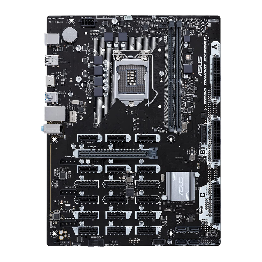
HDMI LGA1151 side towards the rear of the U31G1_56 chassis Intel I219V LAN_U31G1_34 U31G1_12 AUDIO PCIEX16_A1 AUXPWR_A1 Super Intel ® B250 AUXPWR_A2 1167 64Mb BIOS AUXPWR_A3 SATA6G_3 SATA6G_4 CLRTC USB910 SATA6G_2 SATA6G_1 PANEL SPDIF_OUT AAFP Scan the QR code to get the detailed pin definitions. ASUS B250 MINING EXPERT... - Page 9 • In order to fully support 19 graphic cards mining, we recommend that you use 3 power supply units (PSU) that are designed for mining with sufficient 12V power plugs and provide a minimum power of 3750W in total (2*1250W + 1*1350W are recommended). • AUXPWR_A1/A2/A3 must be connected to the same power supply plugged in the 24-pin EATXPWR_A connector. • We recommend that you use a PSU with higher power output when configuring a system with more power-consuming devices or when you intend to install additional devices. The system may become unstable or may not boot up if the power is inadequate. • If you are uncertain about the minimum power supply requirement for your system, refer to the Recommended Power Supply Wattage Calculator at http://support. asus.com/PowerSupplyCalculator/PSCalculator.aspx?SLanguage=en-us for details. Intel LGA1151 CPU socket ® Install Intel LGA1151 CPU into this surface mount LGA1151 socket, which is ® designed for 7th/6th Generation Intel Core™ i7 / i5 / i3, Pentium , and Celeron ® ® ® processors. For more details, refer to Central Processing Unit (CPU). CPU and chassis fan connectors (4-pin CPU_FAN, 4-pin CHA_FAN) Connect the fan cables to the fan connectors on the motherboard, ensuring that the black wire of each cable matches the ground pin of the connector.
- Page 10 B250 Serial ATA 6.0Gb/s connectors (7-pin SATA6G_1~4) ® These connectors connect to Serial ATA 6.0 Gb/s hard disk drives via Serial ATA 6.0 Gb/s signal cables. USB 2.0 connector (10-1 pin USB910) Connect a USB module cable to this connector, then install the module to a slot opening at the back of the system chassis. These USB connectors comply with USB 2.0 specifications and supports up to 480Mbps connection speed. Serial port connector (10-1 pin COM) Connect the serial port module cable to this connector, then install the module to a slot opening at the back of the system chassis. Digital audio connector (4-1 pin SPDIF_OUT) Connect the S/PDIF Out module cable to this connector, then install the module to a slot opening at the back of the system chassis. PIN 1 SPDIF_OUT ASUS B250 MINING EXPERT...
- Page 11 Front panel audio connector (10-1 pin AAFP) This connector is for a chassis-mounted front panel audio I/O module that supports either HD Audio or legacy AC`97 audio standard. Connect one end of the front panel audio I/O module cable to this connector. • We recommend that you connect a high-definition front panel audio module to this connector to avail of the motherboard’s high-definition audio capability. • If you want to connect a high-definition front panel audio module to this connector, set the Front Panel Type item in the BIOS setup to [HD Audio]. If you want to connect an AC’97 front panel audio module to this connector, set the item to [AC97]. By default, this connector is set to [HD Audio]. PCI Express x16 slot This motherboard supports one PCI Express x16 graphic cards that comply with the PCI Express specifications. PCI Express x1 slots This motherboard has eighteen PCI Express x1 slots that support PCI Express x1 network cards, SCSI cards, and other cards that comply with the PCI Express specifications. For more details, refer to Expansion slots. 1.2.2 Rear panel connectors PS/2 Mouse port. This port connects to a PS/2 mouse. USB 2.0 ports. These 4-pin Universal Serial Bus (USB) ports are for USB 2.0/1.1 devices.
- Page 12 Mic In Bass/Center Bass/Center Lime (Front panel) Side Speaker Out To configure a 7.1-channel audio output: Use a chassis with HD audio module in the front panel to support a 7.1-channel audio output. USB 3.1 Gen 1 ports (blue, Type A). These 9-pin Universal Serial Bus (USB) ports are for USB 3.1 Gen 1 devices. • USB 3.1 Gen 1 devices can only be used for data storage. • We strongly recommend that you connect USB 3.1 Gen 1 devices to USB 3.1 Gen 1 ports for faster and better performance from your USB 3.1 Gen 1 devices. • Due to the design of the Intel 200 series chipset, all USB devices connected to the ® USB 2.0 and USB 3.1 Gen 1 ports are controlled by the xHCI controller. Some legacy USB devices must update their firmware for better compatibility. PS/2 Keyboard port. This port connects to a PS/2 keyboard. ASUS B250 MINING EXPERT...
-
Page 13: Central Processing Unit (Cpu)
Central Processing Unit (CPU) This motherboard comes with a surface mount LGA1151 socket designed for the 7th/6th Generation Intel Core™ i7 / Core™ i5 / Core™ ® i3, Pentium and Celeron processors. ® ® Unplug all power cables before installing the CPU. • Ensure that you install the correct CPU designed for the LGA1151 socket only. DO NOT install a CPU designed for LGA1150, LGA1155 and LGA1156 sockets on the LGA1151 socket. • Upon purchase of the motherboard, ensure that the PnP cap is on the socket and the socket contacts are not bent. Contact your retailer immediately if the PnP cap is missing, or if you see any damage to the PnP cap/socket contacts/motherboard components. • Keep the cap after installing the motherboard. ASUS will process Return Merchandise Authorization (RMA) requests only if the motherboard comes with the cap on the LGA1151 socket. • The product warranty does not cover damage to the socket contacts resulting from incorrect CPU installation/removal, or misplacement/loss/incorrect removal of the PnP cap. Installing the CPU Apply the Thermal Interface Material to the CPU heatsink and CPU before you install the heatsink and fan if necessary. Chapter 1: Product introduction... -
Page 14: System Memory
® the CPU. • Due to Intel chipset limitation, DDR4 2400MHz memory frequency is only supported ® by 7th Generation Intel processors. Higher memory modules will run at the maximum ® transfer rate of DDR4 2400MHz. • Due to Intel chipset limitation, DDR4 2133MHz and higher memory modules on 6th ® Generation Intel processors will run at the maximum transfer rate of DDR4 2133MHz. ® • Memory modules with memory frequency higher than 2133/2400 MHz and its corresponding timing or the loaded X.M.P. Profile is not the JEDEC memory standard. The stability and compatibility of these memory modules depend on the CPU’s capabilities and other installed devices. • To make your build more stable, when using 8 or more mining cards, we recommend that you install 4GB memory modules and change the size of the virtual memory paging file to 20GB. • The default memory operation frequency is dependent on its Serial Presence Detect (SPD), which is the standard way of accessing information from a memory module. Under the default state, some memory modules for overclocking may operate at a lower frequency than the vendor-marked value. • For system stability, use a more efficient memory cooling system to support a full memory load (2 DIMMs). • Refer to www.asus.com for the latest Memory QVL (Qualified Vendors List) ASUS B250 MINING EXPERT... -
Page 15: Expansion Slots
Installing a DIMM To remove a DIMM Expansion slots This motherboard comes with one PCIe x16 and eighteen (18) PCIe x1 expansion card slots that support graphics cards, network cards, and other cards that comply with PCIe specifications. The added expansion slots and power connectors are uniquely designed to support up to 19 mining graphics cards for professional cryptocurrency mining. The following sections describe the location of the expansion slots and power connectors, and how to install the mining cards and connect the power supply unit. The expansion slots and power connectors are divided into three groups, located in three areas and labeled with A, B and C, as shown in the illustrations below. PCIEX16_A1 AUXPWR_A1 AUXPWR_A2 AUXPWR_A3 Chapter 1: Product introduction... - Page 16 19* 18* 17* 16 15 14 13 12 11 10 P106 NVIDIA Regular No limit cards 9-11* * need AMD driver support. To install mining cards: • Seven (7) or less mining cards Install your mining cards into the PCIe x16 slot and the PCIe x1 slots labeled Axx in sequential order A01 ~ A06. Connect your power supply unit (PSU) to the 24-pin EATX power connector labeled EATXPWR_A. AUXPWR_A1/A2/A3 must be connected to the same power supply plugged in the 24-pin EATXPWR_A connector. PCIEX16_A1 AUXPWR_A1 AUXPWR_A2 AUXPWR_A3 ASUS B250 MINING EXPERT...
- Page 17 • 8 ~ 13 mining cards To make your build more stable, when using 8 or more mining cards, we recommend that you install 4GB memory modules and change the size of the virtual memory paging file to 20GB. Install your mining cards into the PCIe x16 slot and the PCIe x1 slots labeled Axx and Bxx in sequential order A01 ~ B12. Connect your power supply unit (PSU) to the 24-pin EATX power connectors labeled EATXPWR_A and EATXPWR_B. To make the power consumption in balance, connect the 6-pin/8-pin power connectors of your mining cards in area A to the power supply unit (PSU) plugged in EATXPWR_A, and mining cards in area B to the power supply unit (PSU) plugged in EATXPWR_B. PCIEX16_A1 AUXPWR_A1 AUXPWR_A2 AUXPWR_A3 Chapter 1: Product introduction 1-10...
- Page 18 • 14 ~ 19 mining cards Install your mining cards into the PCIe x16 slot and the PCIe x1 slots labeled Axx, Bxx and Cxx in sequential order A01 ~ C18. Connect your power supply unit (PSU) to 24-pin EATX power connectors labeled EATXPWR_A, EATXPWR_B and EATXPWR_C. • To make the power consumption in balance, connect the 6-pin/8-pin power connectors of your mining cards in area A to the power supply unit (PSU) plugged in EATXPWR_A, mining cards in area B to the power supply unit (PSU) plugged in EATXPWR_B, and mining cards in area C to the power supply unit (PSU) plugged in EATXPWR_C. • AMD driver support is required for using 17 and more graphics cards. PCIEX16_A1 AUXPWR_A1 AUXPWR_A2 AUXPWR_A3 1-11 ASUS B250 MINING EXPERT...
- Page 19 Changing the mining mode in BIOS To change the mining mode in BIOS: Press <Delete> or <F2> during POST to enter BIOS Setup. Go to the Advanced menu > Mining Mode. This item is set to [Enabled] by default. You can change this item by yourself. Viewing the mining card status To view the mining card status in BIOS: Press <Delete> or <F2> during POST to enter BIOS Setup. Go to the Advanced menu > On Board Slot States, then press <Enter> to display the status of the expansion cards. Chapter 1: Product introduction 1-12...
- Page 20 To view the mining card status during POST: An image appears during POST to display the status of the mining cards. Working Error None • Green slot: The mining card works normally. • Red slot: There is an error with the mining card. • Gray slot: Your system failed to detect the mining card. To make your build more stable, when using 8 or more mining cards, we recommend that you install 4GB memory modules and change the size of the virtual memory paging file to 20GB. 1-13 ASUS B250 MINING EXPERT...
-
Page 21: Chapter 2: Bios Information
The BIOS setup screens shown in this section are for reference purposes only, and may not exactly match what you see on your screen. Visit the ASUS website at www.asus.com to download the latest BIOS file for this • motherboard. -
Page 22: Ez Mode
EZ Mode By default, the EZ Mode screen appears when you enter the BIOS setup program. The EZ Mode provides you an overview of the basic system information, and allows you to select the display language, system performance mode, fan profile and boot device priority. To access the Advanced Mode, click Advanced Mode(F7) or press <F7>. -
Page 23: Advanced Mode
Menu bar MyFavorite Hot Keys Language Last modified Pop-up window Searches Sub-menu item General help Scroll bar settings Menu items Configuration Goes back to EZ Mode fields Displays the CPU temperature, CPU and memory voltage output ASUS B250 MINING EXPERT... -
Page 24: Exit Menu
Search on FAQ Move your mouse over this button to show a QR code. Scan this QR code with your mobile device to connect to the ASUS BIOS FAQ web page. You can also scan the QR code below. Exit menu The Exit menu items allow you to load the optimal default values for the BIOS items, and save or discard your changes to the BIOS items. -
Page 25: Appendix
: (1) cet appareil ne doit pas provoquer d’interférences et (2) cet appareil doit accepter toute interférence, y compris celles susceptibles de provoquer un fonctionnement non souhaité de l’appareil. ASUS B250 MINING EXPERT... - Page 26 ASUS Recycling/Takeback Services ASUS recycling and takeback programs come from our commitment to the highest standards for protecting our environment. We believe in providing solutions for you to be able to responsibly recycle our products, batteries, other components as well as the packaging materials.
- Page 27 Slovensky Spoločnosť ASUSTeK Computer Inc. týmto vyhlasuje, že toto Cijeli tekst EU izjave o sukladnosti dostupan je na: www.asus.com/support zariadenie vyhovuje základným požiadavkám a ostatým príslušným ustanoveniam príslušných smerníc. Celý text vyhlásenia o zhode pre štáty EÚ...
-
Page 28: Asus Contact Information
+1-510-739-3777 +1-510-608-4555 Web site http://www.asus.com/us/ Technical Support Support fax +1-812-284-0883 Telephone +1-812-282-2787 Online support http://qr.asus.com/techserv ASUS COMPUTER GmbH (Germany and Austria) Address Harkort Str. 21-23, 40880 Ratingen, Germany +49-2102-959931 Web site http://www.asus.com/de Online contact http://eu-rma.asus.com/sales Technical Support Telephone +49-2102-5789555 Support Fax... - Page 29 CA 94539. Phone/Fax No: (510)739-3777/(510)608-4555 hereby declares that the product Product Name : Motherboard Model Number : B250 MINING EXPERT Conforms to the following specifications: FCC Part 15, Subpart B, Unintentional Radiators Supplementary Information: This device complies with part 15 of the FCC Rules. Operation is subject to the...