Motorola APX 6000XE User Manual
Hide thumbs
Also See for APX 6000XE:
- User manual (194 pages) ,
- Quick reference card (2 pages) ,
- Service manual (438 pages)

Related Manuals for Motorola APX 6000XE


Summary of Contents for Motorola APX 6000XE
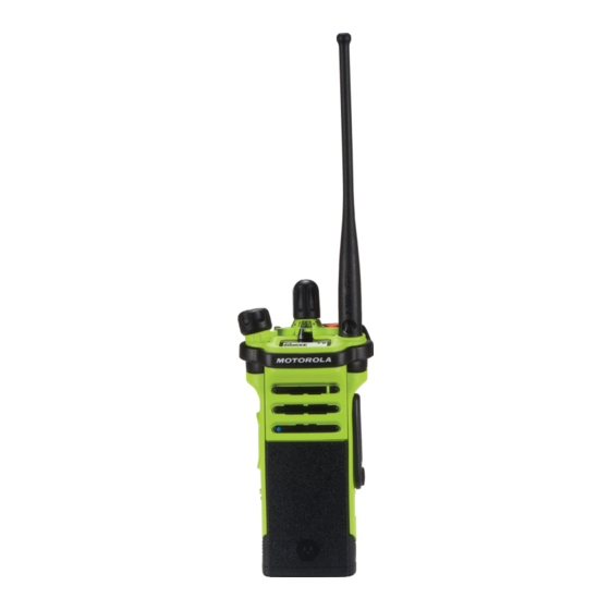
- Page 1 APX TWO-WAY RADIOS APX 6000XE Model 2 USER GUIDE APRIL 2017 *68012003048* 2017 Motorola Solutions, Inc. All rights reserved © 68012003048-GF...
-
Page 3: Table Of Contents
English Contents Chapter 7: Preparing Your Radio for Use....29 Charging the Battery..........29 Attaching the Battery ........29 Declaration of Conformity..........13 Attaching the Antenna........30 Chapter 1: Important Safety Information...... 15 Removing and Attaching the Accessory Chapter 2: Notice to Users (FCC and Industry Connector Cover.......... - Page 4 English Status Icons............47 Receiving and Responding to a Private Call (Trunking Only)........ 66 Text Messaging Service (TMS) Indicators..51 Receiving and Responding to a TMS Status Icons........51 Telephone Call (Trunking Only)....67 TMS Menu Options......... 53 Methods to Make a Radio Call......68 Call Type Icons..........53 Making a Talkgroup Call......
-
Page 5: Send Feedback
English Talkgroup Call Feature (Conventional Scan Lists............84 Operation Only)........76 Viewing a Scan List........ 84 Selecting a Talkgroup....76 Editing the Scan List....... 85 Sending a Status Call......77 Changing the Scan List Status....86 Responding to the Dynamic Viewing and Changing the Priority Regrouping Feature (Trunking Only).. - Page 6 English Sending An Emergency Call With Hot Pre-Alert Timer........104 Mic (Trunking Only)........ 94 Post-Alert Timer........104 Sending an Emergency Alarm with Radio Alerts When Man Down Feature Emergency Call........95 is Triggered...........104 Sending An Emergency Alarm and Call Triggering Emergency......104 with Hot Mic..........
- Page 7 English Removing a Priority Status from Managing Encryption......119 a Text Message......112 Loading an Encryption Key..119 Appending a Request Reply to a Multikey Feature......119 Text Message......112 Selecting an Encryption Key..120 Removing a Request Reply from Selecting a Keyset.....
- Page 8 Re-Pair Timer........138 Measuring the Distance and Bearing Bluetooth Drop Timer......139 from a Saved Waypoint......130 Pairing with Low Frequency-Motorola Location Feature in Emergency Mode.. 130 Proximity Pairing (LF-MPP) Feature..140 Peer-Location on the Display (ASTRO Radio Indications of Lost Bluetooth Conventional only)........
- Page 9 English Pairing the Authentication PIN Sending SSA Notification to Single Site with the Generated Numeric PIN ..............155 ........... 146 Sending SSA Notification to All Sites..156 Turning On the Bluetooth Audio... 147 Sending SSA Notification to All Turning Off the Bluetooth Audio... 148 Available Sites........
- Page 10 English Enabling and Disabling the Radio Alias Accessing the Battery Info ..............165 screen........173 Controlling the Display Backlight..165 General Radio Information....173 Locking and Unlocking the Controls..166 Accessing the Radio Information ........... 173 Turning the Controls and Buttons Tones On or Off........166 Viewing the IP Information..
- Page 11 Distress and Safety Frequencies.....188 Technical Parameters for Interfacing External Data Sources...........188 Chapter 15: Glossary..........189 Chapter 16: Limited Warranty........195 MOTOROLA SOLUTIONS COMMUNICATION PRODUCTS....195 I. WHAT THIS WARRANTY COVERS AND FOR HOW LONG:........... 195 II. GENERAL PROVISIONS:......196 III. STATE LAW RIGHTS:........197 IV.
- Page 12 English This page intentionally left blank.
-
Page 13: Declaration Of Conformity
Name: Motorola Solutions, Inc. Address: 1303 East Algonquin Road, Schaumburg, IL 60196-1078, U.S.A. Phone Number: 1-800-927-2744 Hereby declares that the product: Model Name: APX 6000XE conforms to the following regulations: FCC Part 15, subpart B, section 15.107(a), 15.107(d), and section 15.109(a) Table continued…... - Page 14 English Class B Digital Device As a personal computer peripheral, this device complies with Part 15 of the FCC Rules. This device complies with Industry Canada license-exempt RSS standard(s). Operation is subject to the following two conditions: 1 This device may not cause harmful interference, and 2 This device must accept any interference received, including interference that may cause undesired operation.
-
Page 15: Chapter 1: Important Safety Information
RF energy awareness and control for Compliance with applicable standards and Regulations. For a list of Motorola Solutions-approved antennas, batteries, and other accessories, visit the following website: http://www.motorolasolutions.com/APX Under Industry Canada regulations, this radio transmitter... - Page 16 English This page intentionally left blank.
-
Page 17: Chapter 2: Notice To Users (Fcc And Industry Canada)
• Changes or modifications made to this device, not expressly approved by Motorola Solutions, could void the authority of the user to operate this equipment. Software Version All the features described in the following sections are supported by the software version R16.00.00 or later. - Page 18 English This page intentionally left blank.
-
Page 19: Chapter 3: Computer Software Copyrights
English Computer Software Copyrights The Motorola Solutions products described in this manual may include copyrighted Motorola Solutions computer programs stored in semiconductor memories or other media. Laws in the United States and other countries preserve for Motorola Solutions certain exclusive rights for... - Page 20 English This page intentionally left blank.
-
Page 21: Chapter 4: Documentation Copyrights
No duplication or distribution of this document or any portion thereof shall take place without the express written permission of Motorola Solutions. No part of this manual may be reproduced, distributed, or transmitted in any form or by any means, electronic or mechanical, for any purpose without the express written permission of Motorola Solutions. - Page 22 English This page intentionally left blank.
-
Page 23: Chapter 5: Disclaimer
The information in this document is carefully examined, and is believed to be entirely reliable. However, no responsibility is assumed for inaccuracies. Furthermore, Motorola Solutions reserves the right to make changes to any products herein to improve readability, function, or design. Motorola Solutions does not assume any liability arising out of the applications or use of any product or circuit described herein;... - Page 24 English This page intentionally left blank.
-
Page 25: Chapter 6: Getting Started
English Getting Started NOTICE: An operational procedure, practice, or condition and so on, which is essential to emphasize. How to Use This Guide The following special notations identify certain items. This User Guide covers the basic operation of the APX Portables. -
Page 26: Astro 25 Enhanced Data
SecureNet traffic. SecureNet allows user to perform secured communications on an Analog or Motorola Data Communication (MDC) Dynamic System Resilience (DSR) channel. The MDC Over-the-Air Rekeying (OTAR) feature DSR ensures the radio system is seamlessly switched to a will allow users to perform OTAR activities on an MDC backup master site dynamically in case of system failure. -
Page 27: What Your Dealer/System Administrator Can Tell You
English the busy LED when activity is present on the channel. • Is your radio programmed with any preset conventional Mixed Vote Scan and Standard Conventional Scan channels? configurations are supported. Priority Operation is also • Which buttons have been programmed to access other supported. - Page 28 English This page intentionally left blank.
-
Page 29: Chapter 7: Preparing Your Radio For Use
To charge the battery, place the battery (with or This section provides simple instructions to prepare your without the radio) in a Motorola Solutions-approved radio for use. charger. The LED on the charger indicates the charging Charging the Battery progress;... -
Page 30: Attaching The Antenna
English 2 To remove the battery, squeeze the release latches Attaching the Antenna at the bottom of the battery until the battery releases from the radio and remove the battery from Ensure the radio is turned off before attaching the antenna. the radio. -
Page 31: Removing And Attaching The Accessory Connector Cover
English Removing and Attaching the Accessory Connector Cover The accessory connector is on the antenna side of the radio. It is used to connect accessories to the radio. NOTICE: To prevent damage to the connector, shield it with the connector cover when not in use. 1 To remove the accessory connector cover, rotate the thumbscrew counterclockwise until it disengages... -
Page 32: Using The Carry Holder
English Using the Carry Holder 1 Position the radio within the carry holder with the main speaker facing outward. 2 Rotate and lift the connector cover to disengage it from the radio. 3 To attach the accessory connector cover, insert the hooked end of the cover into the slot above the connector. - Page 33 English 3 To remove the radio from the carry holder, place the tip of your fingers on the ledge of the carry holder. 4 Push at the bottom of the radio until the radio is released from it. Send Feedback...
-
Page 34: Turning On The Radio
English • If the power-up test is successful, you see a Turning On the Radio splash screen on the radio display, followed by the Home screen. 1 Rotate the On/Off/Volume Control Knob clockwise • If the power-up test is unsuccessful, you see until you hear a click. -
Page 35: Adjusting The Volume
English 2 To turn off the radio, rotate the On/Off/Volume 1 To increase the volume, rotate the On/Off/Volume Control Knob counterclockwise until you hear a Control Knob clockwise. click. 2 To decrease the volume, rotate this knob counterclockwise. Adjusting the Volume Ensure the radio is powered on and the main speaker is pointed towards you for increased loudness and intelligibility, especially in areas with loud background... - Page 36 English This page intentionally left blank.
-
Page 37: Chapter 8: Identifying Radio Controls
English Identifying Radio Controls Radio Parts and Controls This chapter explains the buttons and functions to control the radio. Send Feedback... - Page 38 English Top (Orange) Button Microphone Accessory Connector Home Button 4–Way Navigation Button Battery Latch Data Feature Button Menu Select Buttons Main Display 3–Position A/B/C Switch On/Off/Volume Control Knob 2–Position Concentric Switch Top Display Top Side (Select) Button Antenna Push-to-Talk (PTT) Button 16–Position Select Knob Side Button 1 Table continued…...
-
Page 39: Programmable Features
English Hold down Side Button 2 Keeping the button pressed. Battery Bluetooth Pairing Location Indicator Assignable Radio Functions Main Speaker Bluetooth On/Off Microphone Allows you to turn on/off the Bluetooth. Bluetooth Configuration Allows you to access to the Bluetooth menu. Bluetooth Audio Reroute Programmable Features Allows you to toggle the audio route between radio... - Page 40 English Bluetooth Discoverable On/Off Location Enables Bluetooth visibility. This is accessed by a long Determines the current location (latitude, longitude, time press of the Bluetooth Inquiry On/Off Button. and date), and also the distance and bearing to another location or turns the GPS functionality on or off for all Call Alert locations.
- Page 41 English Nuisance Delete Rekey Request Temporarily removes an unwanted channel, except for Notifies the dispatcher that a new encryption key is priority channels or the designated transmit channel needed. from the scan list. Repeater Access Button (RAB) (Conventional Only) One Touch 1–4 Allows user to manually send a repeater access Launches a specific feature with one single button- codeword.
-
Page 42: Assignable Settings Or Utility Functions
English Site Display/Search (Trunking Only) Basic Zone Bank Displays the current site ID and RSSI value; performs Provides access from up to six zones by toggling site search for Automatic Multiple Site Select (AMSS) or between two banks of three zones, one group of three SmartZone operation. -
Page 43: Accessing The Preprogrammed Functions
English Voice Mute Softkeys Toggles voice mute on or off. Menu Select Buttons Volume Set Tone Data Feature Button Sets the volume set tone. 4–Way Navigation Button Accessing the Preprogrammed Home Button Functions Menu Select Buttons You can access various radio functions through one of the following methods. -
Page 44: 4-Way Navigation Button
English user-edited radio settings or information before returning Push-To-Talk (PTT) Button you to the Home screen. NOTICE: Some features do not require you to press to go to the Home screen. Refer to the individual feature sections in this manual for further details on saving user-edited radio settings or information. - Page 45 English • While a call is not in progress, the PTT button is used to make a new call. See Methods to Make a Radio Call on page 68 for more information. Send Feedback...
- Page 46 English This page intentionally left blank.
-
Page 47: Chapter 9: Identifying Status Indicators
English Identifying Status Indicators Transmitting Radio is transmitting a call or data. Top Dis- This chapter explains the status indicators used in the play: radio. Status Icons Call Received Radio has received an Individual Call. The 130 x 130 pixel front liquid crystal display (LCD) of your radio shows radio status, text entries, and menu Battery entries. - Page 48 English Roaming The radio has roamed to and is currently The feature is enabled. Voice muting of registered to a foreign system. the affiliated trunking talkgroup or selec- Top Dis- ted conventional channel is activated. play: The feature is disabled. Voice muting of the affiliated trunking talkgroup or selec- Direct ted conventional channel is deactivated.
- Page 49 English Blinking dot Radio detects activity on channel desig- Radio is in Zone 2. nated as Priority-One. Steady dot Radio is in Zone 3. Radio detects activity on channel desig- Top Dis- Basic Zone Bank 2 nated as Priority-Two. play: Top Dis- View/Program Mode Radio is in Zone 4.
- Page 50 English GPS Signal Contains Zone 70, Zone 71, and Zone Feature is enabled and signal is availa- ble. Contains Zone 73, Zone 74, and Zone Feature is disabled. Secure Operation Blinking Feature is enabled, but no signal is Top Dis- available.
-
Page 51: Text Messaging Service (Tms) Indicators
English Text Messaging Service (TMS) Inverted User successfully login to the secured Indicators IP Packet Data. Status icons and menu options shown here help you to Data Activity work more efficiently with TMS feature. See Text Data activity is present. Messaging Service (TMS) on page 110 for more information. - Page 52 English • User receives a new message. • Messages in the Inbox folder are flagged with “Priority”. • The selected text message in the Inbox has not been read. Request Reply Read Message • The “Request Reply” feature is toggled on before the message is sent.
-
Page 53: Tms Menu Options
English TMS Menu Options Call Type Icons The following menu options appear on the radio display The following icons appear on the radio main display, when when you send and receive text messages. you make or receive a call, or view selected call lists, to indicate the different call types associated with an alias or Menu Description/Function... -
Page 54: Led Indicator
English Blinking red Incoming call or data. Radio is transmitting at low battery condition. Double blinking red Outgoing call or data. Radio is in Emergency Mode. Rapidly blinking red Incoming emergency call. Radio has failed the self test upon powering up or encountered a fatal error. -
Page 55: Intelligent Lighting Indicators
English NOTICE: indication can be preprogramed by qualified No LED indication when the radio receives a clear technician to be permanently disabled. Consult your (non-secured) transmission in trunking Mode. LED dealer for further details if you want to disable it. Intelligent Lighting Indicators This feature temporarily changes the backlight of the top display screen, and adds a color bar to the main display screen to help signal that a radio event has occurred... -
Page 56: Alert Tones
English Backlight and Bar Notification When Color The radio is unable to authenticate or register with the system. The radio lost GPS signal or GPS function fails. Green Call Alerts The radio receives a private call. The radio receives a phone call. The radio receives a call alert. - Page 57 English You Hear Tone Name Heard No ACK Received When radio fails to receive an acknowledgment. Individual Call Warning When radio is in an individual call for greater than six seconds Tone without any activity. Man Down Entry When radio initiates Man Down mode. Long, Low- Time-Out Timer Timed Out After time out.
- Page 58 English You Hear Tone Name Heard Short, Medi- Valid Key-Press When a correct key is pressed. um-Pitched Radio Self Test Pass When radio passes its power-up self test. Tone Clear Voice At beginning of a non-coded communication. Priority Channel Received When activity on a priority channel is received.
- Page 59 English You Hear Tone Name Heard Site Trunking When a SmartZone trunking system fails. Short, High- Low-Battery Chirp When battery is below preset threshold value. Pitched Tone (Chirp) Two High- GPS Fails When the GPS fails or loses signal. Pitched Tones Ringing Fast Ringing When system is searching for target of Private Call.
-
Page 60: Phone Call Displays And Alerts
English You Hear Tone Name Heard Decremental- Bluetooth Unpaired When Bluetooth accessory is unpaired from the radio. Pitched Tone Bluetooth Disconnected When Bluetooth accessory is disconnected from the radio. A Group of Man Down Continuous When radio is in Man Down mode and prepares to transmit Emer- Very High- Tone gency Alarm when the timer of this alarm ends. -
Page 61: Display Color Change On Channel
English You Hear You See When Notes Phone busy The phone system is busy. Press to exit the phone mode and try your call later. A Busy Tone Phone busy When a channel is not The radio automatically connects when a available. - Page 62 English • The radio repetitively displays Wrong Battery with red intelligent backlight • The Battery icon blinks continuously • A repetitive tone sounds • LED blinks RED continuously NOTICE: The radio does not display any indication when the radio is connected to the charger, when the radio and battery match, or when the radio certification type is configured as "None"...
-
Page 63: Chapter 10: General Radio Operation
English General Radio Operation • Select a zone using the radio menu Zone: or to Zone and press the Menu Select button directly below Zone. This chapter explains the general radio operations in your radio. to the required zone. c. Press the Menu Select button directly below Sel Selecting a Zone to confirm the displayed zone. -
Page 64: Mode Select Feature
English A channel is a group of radio characteristics, such as to ChUp or ChDn. transmit/receive frequency pairs. Do one of the following to b. Press the Menu Select button directly below select a radio channel. You can use the options ChUp or ChDn. -
Page 65: Saving A Zone And A Channel To A Softkey
English Saving a Zone and a Channel to a Saving a Zone and a Channel to a Softkey Button Five softkeys are available for you to save the frequently You can save the frequently used zone and channel to the used zone and channel. -
Page 66: Receiving And Responding To A Talkgroup Call
English The radio shows different indicators based on the system • For Trunking system, the display shows the caller alias the radio is configured. or ID. • The LED lights up solid red while the radio is 1 Hold the radio vertically 1 to 2 inches (2.5 to 5.0 cm) transmitting. -
Page 67: Receiving And Responding To A Telephone Call (Trunking Only)
English NOTICE: 3 Press or the Call Response button to hang up With the inactivity timer enabled (optional), when and return to the Home screen. there is no response from the receiving radio, the calling radio exits the call with Menu Inactive Exit See also Making a Private Call (Trunking Only) on page tone after the timer expires. -
Page 68: Methods To Make A Radio Call
English Making a Talkgroup Call 2 Press and hold the PTT button to talk. Release the PTT button to listen. To make a call to a group of users, your radio must be configured as part of that talkgroup. 3 Press or the Call Response button to hang up and return to the Home screen. -
Page 69: Making A Private Call (Trunking Only)
English Making a Private Call (Trunking Only) • to the required ID. Your radio must be preprogrammed for you to use this 3 Press the PTT button to initiate the Private Call. feature. The display shows Calling... <Number>. This feature allows you to send an individual Call Alert or page if there is no answer from the target radio. - Page 70 English This feature allows you to send an individual Call Alert 3 Press the PTT button to initiate the Private Call. Page if there is no answer from the target radio. See The display shows Calling... <Number>. Sending a Call Alert Page on page 89 for more information.
-
Page 71: Making A Telephone Call (Trunking Only)
English Making a Telephone Call (Trunking • to the required phone number. Only) 3 Press the PTT button to dial the phone number. This feature allows you to make calls similar to standard 4 Hold the radio vertically 1 to 2 inches (2.5 to 5.0 cm) phone calls to a mobile or landline phone. -
Page 72: Monitor Feature
English The Direct or “talkaround operation” allows you to bypass Digital technology quiets the transmission by removing the the repeater and connect directly to another radio. The noise from the signal and allows only the clear voice or transmit and receive frequencies are the same. data information to be heard. -
Page 73: Monitoring Conventional Mode
English c. Press and hold the PTT button to transmit. Monitoring Conventional Mode The LED lights up solid red. ® Your radio may be preprogrammed to receive Private-Line (PL) calls. d. Release the PTT button to receive (listen). The Carrier Squelch indicator appears on the 1 Momentarily press the Monitor button to listen for display when you monitor a channel using the activity. - Page 74 English This page intentionally left blank.
-
Page 75: Chapter 11: Advanced Features
English Advanced Features • The LED blinks solid green once to indicate the transmitting radio is pending to receive signal. The speaker unmutes. This chapter explains the operations of the features available in your radio. 1 Hold the radio vertically 1 to 2 inches (2.5 to 5.0 cm) from your mouth. -
Page 76: Talkgroup Call Feature (Conventional Operation Only)
English Talkgroup Call Feature (Conventional 2 To select the required ID, perform one of the following actions: Operation Only) • Press the Menu Select button directly below This feature allows you to define a group of conventional Cnts to scroll through and select the required ID. system users so that they can share the use of a •... -
Page 77: Sending A Status Call
English • to the required Talkgroup. NOTICE: The radio automatically exits the feature, if the 3 Press the Menu Select button directly below Sel to feature inactivity timer is enabled. You will hear the save the currently selected Talkgroup and return to Menu Inactive Exit Tone upon feature exit. -
Page 78: Responding To The Dynamic Regrouping Feature (Trunking Only)
English No traffic is heard on trunked channels while Status Gurgle tone and the display shows the dynamically Calls is selected. If the radio detects no Status Call regrouped channel’s name. activity for six seconds, an alert tone sounds until Press the PTT button to talk. -
Page 79: Classification Of Regrouped Radios
English Select Disabled • or to Rpgm then press the Menu Select Select-disabled radios cannot change channels while button directly below Rpgm to send reprogram dynamically regrouped. The dispatcher has forced the request to the dispatcher. radio to remain on the dynamic-regrouping channel. The display shows Reprogram Rqst and Please The Scan or Private Call feature cannot be selected while wait. -
Page 80: Entering The Dynamic Zone To Select A Dynamic Channel
English Entering the Dynamic Zone to Select a Saving a Channel in the Dynamic Zone Dynamic Channel from List Selection The radio must be in Dynamic Zone in order to perform this or to Zone then press the Menu Select button operation. -
Page 81: Deleting A Channel In The Dynamic Zone
English to the required channel. Press the Menu 3 Press the Menu Select button below Exit to return Select button directly below Sel. to Home screen. The display shows Channel updated. The Home screen shows <Dynamic Zone Channels>. If the channel deleted is the Home channel, the 6 Press the Menu Select button directly below Exit to Home screen shows <Zone Name>“Blank”. -
Page 82: Making A Private Call From Contacts
English • Call ID (Number) or to Cnts and press the Menu Select button • Call Type (Icon) directly below Cnts. • WACN ID (Astro 25 Trunking IDs only) The entries are alphabetically sorted. • System ID to the required subscriber alias. NOTICE: Your radio must be preprogrammed to allow you to 3 Press the Menu Select button directly below Optn... -
Page 83: Adding A Contact To A Call List
English • to the required Call List and press the 8 Press and hold the PTT button to talk. Release the Menu Select button directly below Add to add to PTT button to listen. the Call List. The LED lights up solid red when the PTT button is •... -
Page 84: Viewing Details Of A Contact
English Scan Lists 4 Press the Menu Select button directly below Yes to remove the entry from the Call List, or No to cancel Scan lists are created and assigned to individual channels/ and return to the main display of Contacts. groups. -
Page 85: Editing The Scan List
English • Press the Menu Select button directly below Del 3 Press to exit the current display and return to the to delete the currently displayed channel from the Home screen. scan list. • Press the Menu Select button directly below Rcl Editing the Scan List to view the next member of the scan list. -
Page 86: Changing The Scan List Status
English Changing the Scan List Status • Use the 16-Position Select knob to select another scan list member. 1 Perform one of the following actions: 5 Move the Scan List Programming switch out of • Long press the preprogrammed Scan List programming position. -
Page 87: Scan
English • A Priority-One Channel Scan icon indicates that • Turn the preprogrammed Scan switch to the the current channel is in the scan list as the Scan on or Scan off position to initiate or stop Priority-One channel. The LED rapidly blinks scan. -
Page 88: Deleting A Nuisance Channel
English a. When the radio locks onto the channel Restoring a Nuisance Channel designated as the new Priority-Two channel, press the preprogrammed Dynamic Priority To restore the deleted nuisance channel, perform button. one of the following actions: The radio continues scanning the remaining •... -
Page 89: Receiving A Call Alert Page
English NOTICE: NOTICE: This feature must be preprogrammed by a qualified If the feature inactivity timer is enabled, your radio radio technician. automatically exits the feature when your radio is left idle long enough for the time to expire. You hear the Menu Inactive Exit Tone upon feature exit. - Page 90 English to select the alias or ID, and press the or to Page. PTT button to initiate the call. b. Press the Menu Select button directly below If the target radio does not respond after a Page. preprogrammed period of time, the display shows c.
-
Page 91: Quick Call Ii (Astro P25 Digital Trunking And Conventional)
English Quick Call II (ASTRO P25 Digital The receiving radio must also be pre-programmed to decode the tone to broadcast. Trunking and Conventional) or to QCII, and press the Menu Select button This feature allows the user to broadcast a series of directly below QCII. - Page 92 English • Emergency Alarm NOTICE: To exit emergency at any time, press and hold the • Emergency Call (Trunking Only) preprogrammed Emergency button for about a • Emergency Alarm with Emergency Call second. This timer is programmable from 0–6250 milliseconds by a qualified technician. •...
-
Page 93: Sending An Emergency Alarm
English Sending an Emergency Alarm If no acknowledgement is received, the display shows No acknowledge. The alarm ends when the timer expires and This feature allows you to send a data transmission, which the radio exits the Emergency Alarm mode. identifies the radio sending the emergency, to the dispatcher. -
Page 94: Sending An Emergency Call With Hot Mic (Trunking Only)
English Follow the procedure to send Emergency Call with hot mic 3 Press and hold the PTT button. Speak clearly into on your radio. the microphone. 1 Press the preprogrammed Emergency button. 4 Release the PTT button to end the transmission and wait for a response from the dispatcher. -
Page 95: Sending An Emergency Alarm With Emergency Call
English Sending an Emergency Alarm with does not support emergency and rejects to launch emergency mode. Emergency Call This feature gives your radio priority access on a channel 2 Hold the radio vertically 1 to 2 inches (2.5 to 5.0 cm) for conventional system, and to a talkgroup for trunking from your mouth. -
Page 96: Sending A Silent Emergency Alarm
English Follow the procedure to send Emergency Alarms and Call 4 To exit Emergency Call, press and hold the with hot mic on your radio. preprogrammed Emergency button. Turning off the radio also cancels the emergency 1 Press the preprogrammed Emergency button. state. -
Page 97: Change Of Channels During Emergency
English Change of Channels during Emergency NOTICE: The radio only exits the Emergency state using one For ALL Emergency transmissions, when changing of the ways mentioned in the previous sections. channels: Sending an Emergency Alarm on page Sending an Emergency Call (Trunking Only) on •... -
Page 98: Sending And Receiving Emergency Find Me Beacon
English Sending and Receiving Emergency Find NOTICE: Me Beacon RSSI-Poor will be shown if the distance between transmit radio and receive radios are more than 8 to 10 meters in an open 1 Press the pre-programmed Emergency button to environment. transmit the EFM beacon. -
Page 99: Entering Fireground Zone Channel (Conventional)
English These components provide on-scene and inbuilding radio Entering Fireground Zone Channel coverage, and enhanced personnel accountability and (Conventional) monitoring. The radio helps to indicate your presence on the scene if it 1 Upon powering up, one of the following scenarios is in the range of the Incident Commander command occurs: terminal, or trunking radio system. -
Page 100: Sending Evacuation Tone
English Sending Evacuation Tone 2 Listen for a transmission. Adjust the Volume Control Knob if necessary. This feature enables the evacuation tone to be heard on the transmitting radio and on any radio that is able to 3 Perform one of the following actions: receive the tone instruction. -
Page 101: Tactical Public Safety (Tps) (Conventional Only)
English Your radio sounds the audible response at the profile Tactical Public Safety (TPS) maximum alert tone volume level. The display shows the (Conventional Only) configurable programmed alert text and intelligent lighting. TPS enables the user of a group to identify the start and Perform one of the following actions: the end of a transmission by displaying the caller name or ID on the radio display. -
Page 102: Man Down
English and it is not adjustable. This beacon goes to silent when Man Down user presses the PTT button for voice transmission. Man Down condition is determined based upon the radio tilt Emergency Call De-Key Sidetone angle or a combination of radio tilt angle and the lack of The radio sounds an alert tone to remind radio user that radio motion. - Page 103 English The Man Down feature provides a Clear function to the • Pressing the PTT button suspends the Man Down user. After a Man Down condition has been detected, the timers; releasing the PTT button re-initiates the Pre- user can press a preprogrammed Clear button or Alert Timer.
-
Page 104: Pre-Alert Timer
English Pre-Alert Timer Radio Alerts When Man Down Feature is Triggered This timer sets the amount of time that a Man Down condition must be present before the radio-user is warned The Man Down alert tone volume is directly related to the of the Man Down condition. -
Page 105: Radio Alerts When Man Down Enhanced Is Triggered
English NOTICE: NOTICE: At this point the Man Down features is complete. If the radio is programmed with Silent Emergency, Use normal Emergency procedures to cancel the radio inhibits the alert tone and visual alert Emergency transmissions. associated with the emergency feature. If the radio is programmed in Surveillance Mode, the alert tone can be heard from the radio speaker. -
Page 106: Exiting Man Down Feature
English Exiting Man Down Feature Testing the Man Down Feature If you are not in a real Man Down situation, you should exit Enable the Emergency feature with Silent Alarm disabled, the Man Down feature and prevent emergency from going but not in Surveillance Mode before running this test on the off with the following operation. -
Page 107: Automatic Registration Service (Ars)
English Automatic Registration Service same. You can use the options interchangeably depending on your preference and the programmed functions. (ARS) • Selecting or Changing the ARS mode using the 16- This feature provides an automated data application Position Select knob: registration for the radio. -
Page 108: User Login Feature
English • If the channel or mode selected is • or to User and press the Menu Select button unprogrammed, the display shows directly below User. Unprogrammed. Repeat this step. The display shows the User Login screen. d. Press Sel to confirm the displayed channel. 2 Perform one of the following actions: User Login Feature •... -
Page 109: Logging Out
English • In non-ARS enabled mode, the display shows NOTICE: Offline, with Logt and Exit. Private data refers to all messages in the text messaging Inbox, Draft, and Sent folder. The next user is able to access the Inbox, Draft, and Sent One of the following scenarios occurs: messages if private data is not deleted. -
Page 110: Text Messaging Service (Tms)
English Text Messaging Service (TMS) Each Quick Text message has a maximum length of 50 characters. You can select the required text from the Quick This features allows you to quickly send and receive Text. messages and run database queries directly from your radios. -
Page 111: Priority Status And Request Reply Of A New Text Message
English If the message is not sent, you hear a low tone, the to scroll through the list of messages and display shows Send failed and returns to the main press the Menu Select button directly below Sel to TMS screen. select the required message. -
Page 112: Appending A Priority Status To A Text Message
English Appending a Priority Status to a Text to Mark as Normal and press the Menu Select button directly below Sel to remove the Message priority status from the message. NOTICE: The display shows the normal message icon on the label The Priority Status icon on a message does not bar. -
Page 113: Appending A Priority Status And A Reply Request To A Text Message
English Removing a Priority Status and a Reply to No Req Reply and press the Menu Select button directly below Sel to remove the Request from a Text Message priority status from the message. 1 Press the Menu Select button directly below Optn. The display shows the normal message icon on the label bar. -
Page 114: Receiving A Text Message
English Receiving a Text Message Viewing a Text Message from the Inbox NOTICE: The Inbox can hold up to 30 messages. When you receive a message that is flagged with NOTICE: the Request Reply icon, you must manually respond to read the message if the content fills to the sender that you have received the message. -
Page 115: Replying To A Received Text Message
English to the required aliases or ID and press the 2 Press the Menu Select button directly below Rply to Menu Select button below Sel to view the message. reply to a message. While on the view message screen, press the Menu The display shows a list of Quick Text. -
Page 116: Sent Text Messages
English Sent Text Messages to the required aliases or ID and press the Menu Select button below Sel to view the message. Once a message is sent to another radio, it is saved in the While on the view message screen, press the Menu Sent folder. -
Page 117: Deleting A Text Message
English Deleting All Text Messages to scroll through the address list and select the required address. 1 Perform one of the following actions: 4 Press the Menu Select button below Send or the • Press the Data Feature button or the PTT button to send the message. -
Page 118: Secure Operations
The Secure/Clear switch only applies when the conventional channels. radio is transmitting. Unlike other forms of security, Motorola Solutions digital encryption provides signaling that makes it virtually Selecting Clear Transmissions impossible for others to decode any part of an encrypted message. -
Page 119: Managing Encryption
English in the strapped mode of operation, regardless of 1 Attach the KVL to your radio. the Secure/Clear switch setting. This option must The display shows Keyloading, and all other radio be preprogrammed by a qualified radio functions, except for power down, backlight, and technician. -
Page 120: Selecting An Encryption Key
English Conventional Multikey to scroll through the encryption keys. The encryption keys are strapped on a one-per-channel basis, through CPS. In addition, you can have operator- 4 Perform one of the following actions: selectable keys, operator-selectable keysets, and • Press the Menu Select button directly below Sel operator-selectable key erasure. -
Page 121: Erasing The Selected Encryption Keys
English different keys structured to another keyset; by changing Erasing the Selected Encryption Keys keysets, you would automatically switch from one set of This feature allows you to erase all or selected encryption keys to the other. keys. Every channel to which one of the original keys was tied Do one of the following to erase the selected encryption now has the equivalent new key instead. -
Page 122: Requesting An Over-The-Air Rekey (Astro Conventional Only)
English e. Select Erase all keys? or Erase single key? by Requesting an Over-the-Air Rekey pressing the Menu Select button below Yes to (ASTRO Conventional Only) erase the encryption key(s) in the radio. Ensure that the Unique Shadow Key (USK) is loaded into You can return to the previous screen by the radio with the key-variable loader (KVL) before the pressing the Menu Select button below No. -
Page 123: Mdc Over-The-Air Rekeying Page
English NOTICE: encryption keys are erased. Without this UKEK key, the The rekey operation failure indicates that radio cannot be rekeyed over the air. your radio does not contain the USK. NOTICE: This feature must be preprogrammed by a qualified radio technician. -
Page 124: Global Positioning System/Global Navigation Satellite System
English Random FM Noise Canceller (Flutter Fighter) The availability and accuracy of this location information Reduces the unwanted effects of random FM noise (and the amount of time that it takes to calculate it) varies pulses caused by channel fading under high Signal-to- depending on the environment in which you are using the Noise (S/N) conditions such as in a moving GPS feature. -
Page 125: Gps Performance Enhancement
English • Under any metal, or concrete roof, or structure Plan. These changes may affect the performance of the GPS feature on your radio. • Between tall buildings or under dense tree-cover • In temperature extremes outside the operating limits of GPS Performance Enhancement your radio Sometimes, the GPS feature may be unable to complete a... -
Page 126: Military Grid Reference System (Mgrs) Coordinates
English memory is full, the next waypoints automatically replaces Military Grid Reference System (MGRS) the oldest waypoints in the radio. Coordinates The radio also stores four preprogrammed waypoints. This feature can only be enabled through CPS These coordinates cannot be deleted. configuration. -
Page 127: Saving A Waypoint
English If the radio fails to get a location fix, the display 3 Perform one of the following actions: shows No service and returns to the previous • To obtain a location fix, press the Menu Select display. button directly below On . •... -
Page 128: Viewing A Saved Waypoint
English • to Save as Dest. and press the Menu 1 Press the Menu Select button directly below Optn. Select button directly below Sel and proceed to step to Waypoints and press the Menu Select button directly below Sel. 3 Press the Menu Select button directly below Ok The display shows a list of waypoints. -
Page 129: Deleting A Single Saved Waypoint
English Deleting a Single Saved Waypoint Deleting All Saved Waypoints Ensure your radio shows the current location on the Ensure your radio shows the current location on the screen. screen. NOTICE: 1 Press the Menu Select button directly below Optn. You cannot delete any of the preprogrammed waypoints. -
Page 130: Measuring The Distance And Bearing From A Saved Waypoint
English directly below No to return to the Waypoints main Location Feature in Emergency Mode screen. When the Emergency feature is activated by pressing the The display shows All saved waypnts deleted. emergency button, the radio exits the Location menu and returns to the Home (default) screen so that you can see which channel the emergency signal is going out on. -
Page 131: Geofence (Astro 25 Trunking System)
English another radio without passing through any infrastructure Short location coordinates facility such as repeaters, phone, or DVRS system. Both • PTT ID (This is optional.) the transmitting radio and receiving radio must be • Longitude and latitude configured to enable them to send and/or receive the GPS coordinates. -
Page 132: Entering The Geofence Area
English When the radio enters the predefined Geofence area, your The radio searches the current zone for the channel with radio receives the Dynamic Regroup command from the same talkgroup assigned as the Dynamic Talkgroup and system and immediately connects to a Dynamic Regroup also with same system ID of current trunk system. -
Page 133: Mission Critical Geofence
English present in a Geofence area. This TMS remains open on the This feature also allows the radio to evaluate if the radio is display until user presses exit/home to exit this screen. within the Geofence area in real time. NOTICE: Check with your dealer or qualified technician to If there is another incoming text message before... -
Page 134: Exiting Mission Critical Geofence
English NOTICE: Operating in Failsoft System Depending on how your radio is programmed, you The failsoft system ensures continuous radio may or may not be alerted by Voice Announcement communication during a trunked system failure. If a (VA), TMS display, Intelligent Backlight, and the trunking system fails completely, the radio goes into failsoft Transmit Power Level. -
Page 135: Out-Of-Range Radio
English Out-of-Range Radio feature should be used with caution, since it inhibits roaming to another site in a wide-area system. When your radio goes out of the range of the system, it can You can toggle the lock state between locked and unlocked no longer lock onto a control channel. -
Page 136: Site Display And Search Button
RSSI. accessories. The display shows momentarily the name of the current It is recommended to use Motorola Solutions proprietary site and its corresponding received RSSI. Mission Critical Wireless (MCW) devices with APX radios during Mission Critical operations as other Bluetooth Changing the Current Site devices may or may not meet the mission critical standard. -
Page 137: Turning On Bluetooth
English The default setting for Bluetooth-enabled radio is Bluetooth to Status and press the Menu Select on. See Turning Off the Bluetooth on page 138 to turn off button directly below On. the Bluetooth. The display shows Status On, and appears. -
Page 138: Turning Off The Bluetooth
The user must re- Select button directly below Exit. pair the devices to re-establish a new set of pairing keys. See Pairing with Low Frequency-Motorola • Turning off the Bluetooth using the preprogrammed Proximity Pairing (LF-MPP) Feature on page 140... -
Page 139: Bluetooth Drop Timer
English resume the Bluetooth connection without user Re-Pair Tim- Re-Pair Timer Scenarios intervention. er Options riod of time depending upon the Re-Pair Tim- Re-Pair Timer Scenarios Drop Timer value. If the device er Options fails to reconnect within the period, the accessory then powers off. -
Page 140: Pairing With Low Frequency-Motorola Proximity Pairing (Lf-Mpp) Feature
Area Networking (PAN), Dial-Up Networking (DUN), include trees, buildings, mountains, cars, and others. Commercial Off- The-Shelf (COTS), and data services. It For high degree of reliability, Motorola Solutions depends on the specifications of these external devices. recommends to NOT separate the radio and the accessory. -
Page 141: Radio Indications Of Lost Bluetooth Connection
English At the fringe areas of reception, both voice and tone quality NOTICE: will start to sound "garbled" or "broken". To correct this If the connection fails within 6 seconds, you hear a problem, simply position the accessory and radio closer to decremental-pitched tone to indicate that the device each other (within the 10 meter defined range) to re- is unpaired. -
Page 142: Standard Pairing Feature
English If the Bluetooth device successfully re-connects before the This feature also enables your Bluetooth enabled radio to Bluetooth 10 second Re-Connection Timer expires, the be visible to other Bluetooth enabled devices and receive display shows momentary <Device Type> connected, request to pair from other devices. -
Page 143: Turning On Bluetooth Visibility
English To continue with Bluetooth pairing, see Pairing with Low • or to BT. Press the Menu Select button Frequency-Motorola Proximity Pairing (LF-MPP) Feature directly below BT to access the Bluetooth feature on page 140. screen. to Search Devices and press the Menu Select button directly below On. -
Page 144: Receiving Pairing Request From Other Devices
English • Turn on Bluetooth visibility using the preprogrammed Receiving Pairing Request from other button. Devices a. Press the preprogrammed button to enable the When your radio receives a pairing request from other Bluetooth visibility feature. device, the display shows <Device Friendly Name>pair request. -
Page 145: Pin Authentication In Pairing
English to Visibility and press the Menu Select to pair before initiating the pairing. Authentic PIN is used for button directly below Off. the verification. The display shows Visibility Off. NOTICE: The pairing PIN authentication method is only When the timer expires, the status changes to applicable for Bluetooth version 2.1 and above. -
Page 146: Pairing The Authentication Pin With The Generated Numeric Pin
English If you choose to reject the pairing process, the • The display shows <Device Friendly Name> display shows Cancel pairing in progress... pair failed (if the pairing timer expires). followed by <Device Friendly Name> pair • The display shows <Device Friendly Name> canceled and return to Home screen. -
Page 147: Turning On The Bluetooth Audio
English If unsuccessful, the display shows BT profiles not Turning On the Bluetooth Audio supported. The display returns to Available Dev Do one of the following to turn on the Bluetooth audio. You screen. can use the options interchangeably depending on your preference and the programmed functions. -
Page 148: Turning Off The Bluetooth Audio
English BT audio routing can be configured in CPS to route to Bluetooth spkr and press the Menu the audio to RSM or radio's internal speaker. The Select button directly below Off. audio routes to the radio's speaker if RSM is not The display shows Off. -
Page 149: Viewing And Clearing The Bluetooth Device Information
English independent from the APX radio. In this case, the volume is If there are no active Bluetooth devices being paired only adjustable on the device. or connected, the display shows No devices. 5 Perform one of the following actions: Adjust volume up/down on the Bluetooth audio device. -
Page 150: Clearing All Bluetooth Devices Information
English NOTICE: If unsuccessful, the radio sounds a short, low- If Re-Pair Timer is set to infinite and you clear keys pitched tone. The display shows Clear all BT on the radio, you must clear keys on all previously devices failed. The display returns to Bluetooth paired devices as well. -
Page 151: Pairing With Lex Handheld
English NOTICE: • You hear a short, low-pitched tone and the If Re-Pair Timer is set to infinite and you clear keys display shows Bluetooth pairing failed (if on the radio, you must clear keys on all previously pairing fails). paired devices as well. -
Page 152: Disabling Holster Sensor Temporarily
English The user can disable the sensor temporarily or 3 When the gun is placed back in the holster, a tone permanently. sounds, the radio enables the OTA sensor notification and the radio displays Sensor On Ensure that Bluetooth feature of your radio is on and the temporarily. -
Page 153: Over-The-Air Programming (Pop 25, Astro 25, And Astro Conventional)
English Over-the-Air Programming (POP 25, Responding to the Notification of Upgrade ASTRO 25, and ASTRO Conventional) 1 The display shows Upgrade? and two short, medium- pitched tones sound every 30 seconds until This feature enables configuration data and firmware to be upgraded to your radio over-the-air. -
Page 154: Voice Announcement
English NOTICE: Each voice announcement is within a limit of three seconds The radio cannot be used while the upgrade is maximum. The sum duration of all different voice being installed. Therefore, make sure to only announcements in a radio shall be no more than 1000 accept the upgrade at a convenient time when seconds. -
Page 155: Site Selectable Alerts (Astro 25)
English zone and channel). The radio announces the current Upon the activation of a SSA, the receiving radios display zone and channel it is transmitting. the alert alias and generate the periodic alert tone. NOTICE: NOTICE: Pressing this preprogrammed playback button Alert alias, alert tone, and alert period can be enables the voice feature to announce in High preprogrammed. -
Page 156: Sending Ssa Notification To All Sites
English to Start Alert and press the Menu Select 6 To return to the Home screen, press the Menu button directly below Sel. Select button directly below Exit. The display shows the Select Site screen. If you are at the site designated to receive this alert, you can hear an alert tone repeated periodically. -
Page 157: Sending Ssa Notification To All Available Sites
English to select the desired <Alert Alias> and 2 Press the Menu Select button directly below SSA. press the Menu Select button directly below Send. The display shows the Site Alert screen. The display shows Sending req. If radio is out of range, roaming to a foreign system to Start Alert and press the Menu Select or in a failsoft situation, the display shows Req button directly below Sel. -
Page 158: Stopping Ssa Notification Of A Single Site
English If radio is out of range, roaming to a foreign system 6 To return to the Home screen, press the Menu or in a failsoft situation, the display shows Req Select button directly below Exit. failed. If you are at the site designated to receive this alert, you If the request is successful, the display shows Req can hear an alert tone repeated periodically. -
Page 159: Stopping Ssa Notification Of All Available Sites
English Stopping SSA Notification of All to Stop Alert and press the Menu Select button directly below Sel. Available Sites The display shows the Select Site screen. or to SSA. to [All Sites] and press the Menu Select button directly below Send. 2 Press the Menu Select button directly below SSA. -
Page 160: Wi-Fi
English a. To toggle the Wi-Fi on or off, press the 5 To return to the Home screen, press the Menu preprogrammed Wi-Fi button. Select button directly below Exit. This button must be preprogrammed by a The SSA Alert for all available sites stop. qualified radio technician. -
Page 161: Utilities
English • or to WiFi and press the Menu Select button 2 Press to exit. directly below WiFi. The display shows the current status of the Wi-Fi as Utilities described next. Searching This chapter explains the operations of the utility functions Looking for available Wi-Fi networks that have been available in your radio. -
Page 162: Using The Flip Display
English Do one of the following to view recent calls. You can use timer expires. You will hear the Menu Inactive Exit Tone the options interchangeably depending on your preference upon feature exit. and the programmed functions. Using the Flip Display •... -
Page 163: Selecting The Power Level
English This feature allows twice as many zones to be accessed of the audio and data functionality of the radio given the from a switch, doubling the amount of switch positions. following conditions. Power level Low enables a shorter transmitting distance and to conserve power. -
Page 164: Selecting A Radio Profile
English Selecting a Radio Profile Menu Select button directly below Exit to exit the screen without making any changes. This feature allows you to manually switch the visual and The radio returns to the Home screen. The profile audio settings of the radio. The display, backlight, alert name on the Home screen indicates the current tones, and audio settings are defined according to the selected radio profile. -
Page 165: Enabling And Disabling The Radio Alias
English A, B, C, ... or Y consist of three zones. You can use the Enabling and Disabling the Radio Alias preprogrammed 3-position A-B-C switch to select the first, This feature allows you to display or hide the radio alias second or third zone in an EZB. -
Page 166: Locking And Unlocking The Controls
English NOTICE: 2 Toggle again to unlock the controls. The backlight setting also affects the Menu Select buttons and Navigation button backlighting accordingly. Turning the Controls and Buttons The backlight remains on for a preprogrammed time before it automatically turns off completely or Tones On or Off returns to the minimum backlight level. -
Page 167: Turning Voice Mute On Or Off
English Turning Voice Mute On or Off If you attempt to do so, the radio automatically stops your transmission, and you hear a talk-prohibit tone. You can enable and disable voice transmission, if needed. The timer is defaulted at 60 seconds, but it can be Do one of the following to turn Voice Mute on or off. -
Page 168: Time And Date Setup
English Time and Date Setup 4 Perform one of the following actions: • to change the selected item. You can set the time and date for your radio. Settings: • or one or more times to move to an item you wish to change. -
Page 169: Using Conventional Squelch Operation Features
English Using Conventional Squelch Operation Option Result Features Digital Carrier-Operated You hear any digital traf- Squelch (COS) fic. This feature filters out unwanted calls with low signal Normal Squelch You hear any digital traffic strength or channels that have a higher than normal having the correct net- background noise. -
Page 170: Digital Ptt Id Support
English NOTICE: If you try to transmit on an active smart-PTT channel, you When this feature is active, the Carrier hear an alert tone, and the transmission is inhibited. The Squelch status indicator is displayed. LED lights up solid yellow to indicate that the channel is busy. -
Page 171: Transmit Inhibit
English NOTICE: Mode Description Acknowledgement of any messages required from two PTT button presses within the the radio is not transmitted if the Transmit Inhibition preprogrammed time limit. is enabled. Transmit Inhibit Enabling Transmit Inhibition This feature is available for APCO 25 trunking, Type II Perform one of the following actions: trunking and Conventional operations for all APX radios. -
Page 172: Disabling Transmit Inhibition
English NOTICE: NOTICE: If the user has disabled TX Inhibit using the If the user has disabled TX Inhibit using the menu and then moves the switch to the softkey and then moves the switch to the position where TX Inhibit is enabled, the new position where TX Inhibit is enabled, the new value overwrites the menu value. -
Page 173: Accessing The Battery Info Screen
English Accessing the Battery Info screen Accessing the Radio Information This feature displays the following radio information: or to Batt. • Host Version • Secure Version 2 Press the Menu Select button directly below Batt. The display shows the details of the battery. •... -
Page 174: Viewing The Ip Information
English • MAC Address Viewing the IP Information NOTICE: This feature displays the device name, IP address, and To return to the Home screen, press at any time. status of your radio. NOTICE: 1 Perform one of the following actions: The device name of your radio is preprogrammed. -
Page 175: Viewing The Control Assignments
English • Press the Menu Select button directly below • Press to return to the Home screen. Back to return to the previous screen. • Press to return to the Home screen. Viewing the Control Assignments This feature displays the programmable radio functions assigned to the controls of your radio for the currently selected channel. - Page 176 English This page intentionally left blank.
-
Page 177: Chapter 12: Helpful Tips
English Helpful Tips Radio Care CAUTION: This chapter explains the radio and battery care. • Your radio casting has a vent port that allows for pressure equalization in the radio. Never poke this vent with any objects, such as needles, tweezers, or screwdrivers.This could create leak paths into the radio and the radio’s submergibility will be lost. -
Page 178: Cleaning Your Radio
Motorola Solutions details the Do not submerge the radio in the detergent disassembly, test, and reassembly procedures solution. -
Page 179: Proper Ways To Handle The Radio
Proper repair and maintenance procedures will assure You can also check the battery charge status using the efficient operation and long life for this product. A Motorola menu entry. See IMPRES Battery Annunciator on page 172 Solutions maintenance agreement will provide expert for more information. -
Page 180: Led And Sounds
English LED and Sounds Gauge Battery Charge When your battery is low: 51% to 75% • the LED blinks red when the PTT button is pressed. • you hear a low-battery “chirp” (short, high-pitched tone). Top Display: Fuel Gauge Icons A blinking fuel gauge icon ( ) is displayed only when the 26% to 50% battery voltage drops to low level. -
Page 181: Battery Recycling And Disposal
10% or less (at 10%, the gauge begins blinking) Top Display: Battery Recycling and Disposal In the U.S. and Canada, Motorola Solutions participates in the nationwide Call2Recycle program for battery collection and recycling. Many retailers and dealers participate in this program. - Page 182 English This page intentionally left blank.
-
Page 183: Chapter 13: Accessories
English Accessories The accessory link below is for APX radios. Not all accessories are FCC certified to operate with all APX models and/or bandsplits. Please refer to the specific APX radio price pages for a list of FCC certified accessories or contact your sales representative for accessory compatibility. - Page 184 English This page intentionally left blank.
-
Page 185: Chapter 14: Maritime Radio Use In The Vhf Frequency Range
English Maritime Radio Use in the • bearing (state whether you are using true or magnetic north) VHF Frequency Range • distance to a well-known landmark • vessel course, speed or destination Special Channel Assignments 5 State the nature of the distress. 6 Specify what kind of assistance you need. -
Page 186: Operating Frequency Requirements
English Operating Frequency Requirements Table 1: VHF Marine Channel List Channel Num- Frequency (MHz) A radio designated for shipboard use must comply with Federal Communications Commission Rule Part 80 as Transmit Receive follows: 156.050 160.650 • on ships subject to Part II of Title III of the 156.100 160.700 Communications Act, the radio must be capable of... - Page 187 English 15** 156.750 156.750 156.175 160.775 156.800 156.800 156.225 160.825 17** 156.850 156.850 156.275 160.875 156.900 161.500 156.325 160.925 156.950 161.550 67** 156.375 156.375 157.000 161.600 156.425 156.425 157.050 161.650 156.475 156.475 157.100 161.700 156.575 156.575 157.150 161.750 156.625 – 157.200 161.800 156.675...
-
Page 188: Declaration Of Compliance For The Use Of Distress And Safety Frequencies
English Declaration of Compliance for the 157.075 161.675 Use of Distress and Safety 157.125 161.725 Frequencies 157.175 161.775 157.225 161.825 The radio equipment does not employ a modulation other than the internationally adopted modulation for maritime 157.275 161.875 use when it operates on the distress and safety frequencies 157.325 161.925 specified in RSS-182 Section 7.3. -
Page 189: Chapter 15: Glossary
English Glossary Bluetooth Bluetooth is an open wireless technology standard for exchanging data over short distances from fixed and This glossary is a list of specialized terms used in this mobile devices with high levels of security. manual. Bluetooth Pairing Bluetooth pairing occurs when two bluetooth devices Acknowledgment of communication. - Page 190 English Channel Dispatcher A group of characteristics such as transmit/receive An individual who has radio system management frequency pairs, radio parameters, and encryption duties. encoding. Control Channel Digital Signal Processing. In a trunking system, one of the channels that is used to Dynamic Regrouping provide a continuous, two-way/data communications A feature that allows the dispatcher to temporarily...
- Page 191 Disconnect. Mission Critical Wireless. Home screen The first display information after the radio completes its self test. Motorola Data Communication. IV&D Menu Entry Integrated Voice and Data. A software-activated feature shown at the bottom of the display – selection of these features is controlled by the...
- Page 192 English Network Access Code Private (Conversation) Call Network Access Code (NAC) operates on digital A feature that lets you have a private conversation with channels to reduce voice channel interference between another radio user in the talkgroup. adjacent systems and sites. Private Line (PL) NiMH A sub-audible tone that is transmitted such that only...
- Page 193 English Selective Call Talkaround A feature that allows you to call a selected individual, Bypass a repeater and talk directly to another unit for intended to provide privacy and to eliminate the easy local unit-to-unit communications. annoyance of having to listen to conversations of no Talkgroup interest to you.
- Page 194 English around the world that are constantly synchronizing with each other. Abbreviated as UTC (English backronym = Universal Time, Coordinated), it is also known as Zulu (Z) Time. Zone A grouping of channels. Send Feedback...
-
Page 195: Chapter 16: Limited Warranty
ASTRO APX 6000XE One (1) Year way for any ancillary equipment not furnished by Portable Units MOTOROLA SOLUTIONS which is attached to or used in Product Accessories One (1) Year connection with the Product, or for operation of the Product... -
Page 196: Ii. General Provisions
INCLUDING CHEMICAL, LIQUID, FIRE, AND OTHER II. GENERAL PROVISIONS: PHYSICAL DAMAGE. Comprehensive coverage is This warranty sets forth the full extent of MOTOROLA available in conjunction with MOTOROLA SOLUTIONS’S SOLUTIONS'S responsibilities regarding the Product. standard Commercial Warranty and starts from the FIRST Repair, replacement or refund of the purchase price, at DAY the radio is put into use. -
Page 197: Iii. State Law Rights
English PRODUCT, TO THE FULL EXTENT SUCH MAY BE obtaining warranty service. You can also call MOTOROLA DISCLAIMED BY LAW. SOLUTIONS at 1-800-927-2744 US/Canada. III. STATE LAW RIGHTS: V. WHAT THIS WARRANTY DOES NOT COVER: SOME STATES DO NOT ALLOW THE EXCLUSION OR... -
Page 198: Patent And Software Provisions
Product was initially distributed from MOTOROLA settlement or compromise, and SOLUTIONS. 3 should the Product or parts become, or in MOTOROLA 10 Scratches or other cosmetic damage to Product SOLUTIONS’s opinion be likely to become, the subject surfaces that does not affect the operation of the of a claim of infringement of a United States patent, that Product. -
Page 199: Vii. Governing Law
VIII. For Australia Only with the Product. The foregoing states the entire liability of This warranty is given by Motorola Solutions Australia Pty MOTOROLA SOLUTIONS with respect to infringement of Limited (ABN 16 004 742 312) of Tally Ho Business Park, patents by the Product or any parts thereof. - Page 200 English please call Motorola Solutions Australia at 1800 457 439. You may also visit our website: http:// www.motorolasolutions.com/XA-EN/Pages/Contact_Us the most updated warranty terms. Send Feedback...