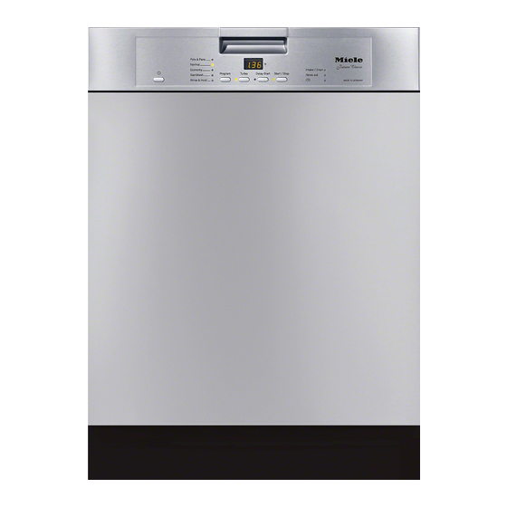
Miele G 4205 Technical Information
G 5 series
futura dishwashers
Hide thumbs
Also See for G 4205:
- Operating instructions manual (52 pages) ,
- Product dimensions (3 pages)
Table of Contents
Advertisement
Quick Links
Advertisement
Table of Contents

Related Manuals for Miele G 4205


Summary of Contents for Miele G 4205
- Page 1 TECHNICAL INFORMATION G 5xxx Futura Dishwashers (All US Models) © 2015 Miele USA...
-
Page 2: Table Of Contents
Fully Integrated Models ................22 3 Component Layouts .................... 23 3.1 G 4205, G 45x0 (Classic, Slimline Dimension with Touchtronic, without Display) ....................23 3.2 G 5105, G 5225 (Crystal with Touchtronic and Display) ......24 ... - Page 3 G 5xxx Technical Information 010 Casing ........................32 2 Function ......................33 2.1 BrilliantLight (Select Models) ..............33 4 Service ........................ 33 4.1 Side Panel Removal ................33 4.2 Drip Pan Removal ..................
- Page 4 G 5xxx Technical Information 4.4 Steam Condenser Removal ..............70 4.5 Fan Removal ..................70 4.6 Connection Box Removal (Select Models) ..........71 4.7 BrilliantLight Control Module Removal ............ 72 050 Water Paths ......................
- Page 5 G 5xxx Technical Information 4.16 Removing the Heater Pressure Switch ..........102 4.17 Removing the Drain Pump ..............102 4.18 Removing the Float ................103 4.19 Removing the Float Switch ..............103 4.20 ...
- Page 6 Electronic Removal (Touchtronic/Novotronic) ........156 300 Technical Service Bulletins ................. 157 1 Miele Policy on Dishwasher Detergent Requirements ........157 2 Dishwasher Detergents and Phosphates ............157 3 G 5000 Inlet Hoses; Update ................158 ...
- Page 7 Figure D-4: Integrated Model ......................21 Figure D-5: Fully Integrated Model ....................22 Figure D-6: G 4205/G 45x0 Component Layout ................23 Figure D-7: G 5105, G 5225 Component Layout ................24 Figure D-8: G 5505, G 5605, G 5705 Component Layout ............25 Figure D-9: G 427x, G 428x, G 4570, G 5175, G 5285 Component Layout .........
- Page 8 G 5xxx Technical Information Figure 040-2: Condenser Pocket ....................67 Figure 040-3: Seal Install Guide ....................68 Figure 040-4: Basket Guide ......................69 Figure 040-5: Clip with Bolt ......................69 Figure 040-6: Fan/Condenser Removal ..................71 Figure 040-7: Connection Box ....................... 71 Figure 040-8: BrilliantLight Control Module ...................
- Page 9 G 5xxx Technical Information List of Tables Table C-1: US Data Sheet, Futura Classic Models ............... 13 Table C-2: US Data Sheet, Futura Crystal Models ............... 14 Table C-3: US Data Sheet, Futura Diamond Models ..............15 Table C-4: US Data Sheet, Futura Dimension Models ..............16 Table C-5: US Data Sheet, Futura Dimension Plus Models ............
-
Page 10: Warning And Safety Instructions
G 5xxx Technical Information Warning and Safety Instructions General Information Danger! The low voltage produced in the electronic is not fully electrically isolated from the power supply. If power supply connection is via a reversible plug, and if this is reversed, then the live (phase) voltage is not applied to terminal [1] or [L] at the terminal block. -
Page 11: Risk Of Injury Due To Sharp Edges And Protruding Parts
G 5xxx Technical Information Risk of Injury Due to Sharp Edges and Protruding Parts Danger! There may be a risk of injury due to protruding parts. Protective goggles should be worn. There may be a risk of injury due to sharp edges. Protective gloves should be worn and the edge protection (mat. -
Page 12: Modification History
G 5xxx Technical Information Modification History When? Who? What? 5/22/2015 Jessica Naples Minor changes throughout 3/23/2015 Jessica Naples Minor changes throughout 3/13/2015 Jessica Naples Minor changes throughout Added tech service bulletin; removed programming and service modes (separate documents); updated 5/16/2014 Jessica Naples data sheets in Section C and component layouts in Section D... -
Page 13: C Technical Data
G 5xxx Technical Information Technical Data Data Sheets Futura Classic Features Model G 4205 G 4225 G 4270 G 4275 G 4281 G 4286 Width 24” Height 32.3” (adj. 33.9” (adj.+ 31.7" (adj. + 33.3" (adj. Built-in 33.9” (adj.+ 2.4”) + 2.4”) -
Page 14: Futura Crystal
G 5xxx Technical Information Futura Crystal Features Model G 5105 G 5175 G 5225 G 5285 Width 24” Height Built-in 33.9” (adj.+ 2.4”) 33.3" (adj. + 2.6") Sensor technology AutoSensor Sensor softener Spray arm sensing None SensorDry Noise level 48dB 46dB Heater rating 1300W... -
Page 15: Futura Diamond
G 5xxx Technical Information Futura Diamond Features Model G 5915 G 5975 Width 24” Height Built-in 33.9” (adj. + 2.4”) 33.9” (adj. + 2.6”) Sensor technology AutoSensor Sensor softener Spray arm sensing Middle and bottom SensorDry Noise level 42dB Heater rating 1300W Circulation pump type MPPW (with frequency converter and slide shutter) -
Page 16: Futura Dimension
G 5xxx Technical Information Futura Dimension Features Model G 45x0 G 5505 G 5570 G 5575 G 5605 G 567x Width 18” 24” Height 32.3” (adj. 33.9” (adj. + 32.3” (adj. 33.9” (adj. Built-in 33.9” (adj. + 2.6”) + 2.4”) 2.4”) + 2.6”) + 2.6”) -
Page 17: Futura Dimension Plus
G 5xxx Technical Information Futura Dimension Plus Features Model G 5705 G 5775 Width 24” Height Built-in 33.9” (adj. + 2.4”) 33.9” (adj. + 2.6”) Sensor technology AutoSensor Sensor softener Spray arm sensing None SensorDry Noise level 45dB Heater rating 1300W Circulation pump type MPPW (frequency converter &... -
Page 18: Door Springs
G 5xxx Technical Information Door Springs Summary Springs are always installed in pairs of the same tensile strength. Color Tensile strength (lbs (N)) Length (in. (mm)) Orange Approx. 52 (230) 5.90 (150) Uncolored Approx. 72 (320) 6.14 (156) Green Approx. 92 (410) 6.10 (155) Table C-6: Door Springs Summary Standard Door Springs by Appliance Model... -
Page 19: Plumbing Connections
Touchtronic This series of Miele dishwashers is operated by pushing a single button – no separate temperature or drying selections – just turn the machine on, select a program and Miele does the rest. All models include a diverse group of wash programs for multiple cleaning needs. -
Page 20: Incognito
Neither seen nor heard, the Miele Incognito Series OCI (Optical Cycle Indicator) lets you see the progress of the dishwasher cycle via a red light, which is steady or flashing depending on the status of the cycle. -
Page 21: Appliance Overviews
G 5xxx Technical Information Appliance Overviews Integrated Models Figure D-4: Integrated Model 1 Upper spray arm (not visible) 7 Filter combination 2 Cutlery tray (model-dependent) 8 Data tag 3 Upper basket 9 Child safety lock in door handle (model-dependent) 4 Middle spray arm 10 Rinse aid reservoir 5 Air inlet for drying (model-dependent) 11 Dual-compartment detergent dispenser... -
Page 22: Fully Integrated Models
G 5xxx Technical Information Fully Integrated Models Figure D-5: Fully Integrated Model 1 Upper spray arm (not visible) 7 Filter combination 2 Cutlery tray (model-dependent) 8 Data tag 3 Upper basket 9 Optical interface 4 Middle spray arm 10 Rinse aid reservoir 5 Air inlet for drying (model-dependent) 11 Dual-compartment detergent dispenser 6 Lower spray arm... -
Page 23: Component Layouts
G 5xxx Technical Information Component Layouts G 4205, G 45x0 (Classic, Slimline Dimension with Touchtronic, without Display) Figure D-6: G 4205/G 45x0 Component Layout 1 Salt float switch, B8/2 13 Heater pressure switch, B1/13 2 Salt container 14 Circulation pump (MPEH), M6... -
Page 24: G 5105, G 5225 (Crystal With Touchtronic And Display)
G 5xxx Technical Information G 5105, G 5225 (Crystal with Touchtronic and Display) Figure D-7: G 5105, G 5225 Component Layout 1 Salt float switch, B8/2 13 Heater pressure switch, B1/13 2 Salt reservoir 14 Circulation pump (MPEH or MPEW), M6 3 Reactivation solenoid, Y38 15 Terminal block, X3/1 4 Wash-water hardness solenoid, Y5... -
Page 25: G 5505, G 5605, G 5705 (Dimension/Dimension Plus With Touchtronic And Display)
G 5xxx Technical Information G 5505, G 5605, G 5705 (Dimension/Dimension Plus with Touchtronic and Display) Figure D-8: G 5505, G 5605, G 5705 Component Layout 1 Salt float switch, B8/2 14 Heater pressure switch, B1/13 2 Salt reservoir 15 Slide shutter, M24 and B3/12 3 Reactivation solenoid, Y38 16 Circulation pump (MPEW or MPPW), M6 4 Wash-water hardness solenoid, Y5... -
Page 26: G 427X, G 428X, G 4570, G 5175, G 5285 (Classic, Dimension, Crystal W/Incognito)
G 5xxx Technical Information G 427x, G 428x, G 4570, G 5175, G 5285 (Classic, Dimension, Crystal w/Incognito) Figure D-9: G 427x, G 428x, G 4570, G 5175, G 5285 Component Layout 1 Salt float switch, B8/2 13 Heater pressure switch, B1/13 2 Salt container 14 Circulation pump (MPEH), M6 3 Reactivation solenoid, Y38... -
Page 27: G 557X, G 567X (Dimension With Incognito)
G 5xxx Technical Information G 557x, G 567x (Dimension with Incognito) Figure D-10: G 557x, G 567x Component Layout 1 Salt float switch, B8/2 14 Heater pressure switch, B1/13 2 Salt container 15 Slide shutter, M24 and B3/12 3 Reactivation solenoid, Y38 16 Circulation pump (MPEW), M6 4 Wash-water hardness solenoid, Y5 17 Terminal block, X3/1... -
Page 28: G 5775 (Dimension Plus With Incognito)
G 5xxx Technical Information G 5775 (Dimension Plus with Incognito) Figure D-11: G 5775 Component Layout 1 Salt float switch, B8/2 14 Main switch, S2 2 Salt container 15 Heater pressure switch, B1/13 3 Reactivation solenoid, Y38 16 Slide shutter, M24 and B3/12 4 Wash-water hardness solenoid, Y5 17 MPPW freq. -
Page 29: G 5975 (Diamond With Incognito)
G 5xxx Technical Information G 5975 (Diamond with Incognito) Figure D-12: G 5975 Component Layout 1 Salt float switch, B8/2 16 BrilliantLight module 2 Salt container 17 Heater pressure switch, B1/13 3 Reactivation solenoid, Y38 18 Slide shutter, M24 and B3/12 4 Wash-water hardness solenoid, Y5 19 MPPW freq. -
Page 30: G 5915 (Diamond With Navitronic)
G 5xxx Technical Information G 5915 (Diamond with Navitronic) Figure D-13: G 5915 Component Layout Salt float switch, B8/2 16 BrilliantLight module Salt container 17 Heater pressure switch, B1/13 Reactivation solenoid, Y38 18 Slide shutter, M24 and B3/12 Wash-water hardness solenoid, Y5 19 MPPW freq. -
Page 31: Data Tag
G 5xxx Technical Information Data Tag Figure D-14: Data Tag Location Figure D-15: Data Tag Information Model Numbering Figure D-16: Model Numbering... -
Page 32: Casing
G 5xxx Technical Information Casing... -
Page 33: Function
G 5xxx Technical Information Function BrilliantLight (Select Models) 4 power LEDs are used to illuminate the interior. 2 power LEDs are located at the top of the door and the other 2 are located in the interior sides of the cabinet. -
Page 34: Drip Pan Removal
G 5xxx Technical Information Figure 010-1: Side Panel Removal Drip Pan Removal Warning! Before tilting the machine onto its back, open the salt container cap briefly, then close it firmly (this empties the water diverter). Then pump all water out of the cabinet. -
Page 35: Hinge Removal
G 5xxx Technical Information Figure 010-2: Drip Pan Removal Warning! When re-installing, it is vital to ensure that screws with a serrated surface under their heads are used to secure the drip pan to the connection strip. This is absolutely essential to ensure a good ground connection. Hinge Removal Note: Hinges must be replaced in pairs. -
Page 36: Brilliantlight Deactivation
G 5xxx Technical Information 9. Disconnect the ground wire from the inner door panel. 10. Remove the cable clip from its guide on the inner door panel. 11. Unhook the door and lay it on a mat. 12. Remove the bottom door seal. 13. -
Page 37: Brilliantlight Activation
G 5xxx Technical Information closed and opened sufficiently such that the light is switched on and off. BrilliantLight Activation 1. Half-open the dishwasher door and quickly partially close and open it three times. 2. Check the function for correct operation and repeat the process, if necessary. -
Page 38: Figure 010-7: Brilliantlight Lens
G 5xxx Technical Information 9. Remove the lens holder from its guide in the cabinet. Figure 010-7: BrilliantLight Lens... -
Page 39: Door
G 5xxx Technical Information Door... -
Page 40: Door Handle And Door Lock (Touchtronic/Navitronic)
G 5xxx Technical Information Function Door Handle and Door Lock (Touchtronic/Navitronic) To open the door, press the release catch inside the door grip. See Figure 020-1. Figure 020-1: Door Handle Release Note: If the door is opened during operation, the dishwasher will stop running. Once the door is closed the program will restart. -
Page 41: Figure 020-3: Drying Plus (Before Program End)
G 5xxx Technical Information Note: The Drying plus function is always active unless it has been deactivated in programming mode. The latch automatically opens the door of the machine for approximately 30 minutes; see Figure 020-4. The door latch advances from position 1 (door closed, latch completely retracted) to position 3 (drying, latch completely extended), i.e. -
Page 42: Figure 020-4: Drying Plus (After Program End)
G 5xxx Technical Information Figure 020-4: Drying Plus (after Program End) 1 Plug 1 2 Plug 2 Figure 020-5: Door Lock Latch Plugs The latch can be set to 3 different positions via a DC motor (16V, 10W). For the electronically controlled comfort door closing aid (G 59x5 models), positioning is controlled via the control-power module (SLT), and monitored via 2 single-pole limit switches. -
Page 43: Figure 020-6: Door Lock Latch, Position 1
G 5xxx Technical Information 1, 2, 3 Latch positions 1, 2, 3 Plug 2 Plug 1 Door switch (120VAC), closed Door movement switch (low voltage), open Door contact switch (120VAC), closed Door-locking motor (DC motor); no voltage applied Figure 020-6: Door Lock Latch, Position 1 Position 2 - Door open, latch at mid-setting, loading/unloading position: If the door is opened, the door lock latch is moved from position 1 to position 2. -
Page 44: Figure 020-7: Door Lock Latch, Position 2
G 5xxx Technical Information 1, 2, 3 Latch positions 1, 2, 3 Plug 2 Plug 1 Door switch (120VAC), open Door movement switch (low voltage), closed Door contact switch (120VAC), open Door-locking motor (DC motor); no voltage applied Figure 020-7: Door Lock Latch, Position 2 Position 3 - Drying, latch completely extended, “Drying plus”... -
Page 45: Figure 020-8: Door Lock Latch, Position 3
G 5xxx Technical Information 1, 2, 3 Latch positions 1, 2, 3 Plug 2 Plug 1 Door switch (120VAC), open Door movement switch (low voltage), closed Door contact switch (120VAC), closed Door-locking motor (DC motor); no voltage applied Figure 020-8: Door Lock Latch, Position 3... -
Page 46: Figure 020-9: Door Lock Latch, Intermediate Opening Position
G 5xxx Technical Information Intermediate position, opening: 1, 2, 3 Latch positions 1, 2, 3 Direction of latch movement Plug 2 Plug 1 Door switch (120VAC), open Door movement switch (low voltage), open Door contact switch (120VAC), closed Door-locking motor (DC motor); voltage applied, motor is opening door Figure 020-9: Door Lock Latch, Intermediate Opening Position... -
Page 47: Figure 020-10: Door Lock Latch, Intermediate Closing Position
G 5xxx Technical Information Intermediate position, closing: 1, 2, 3 Latch positions 1, 2, 3 Direction of latch movement Plug 2 Plug 1 Door switch (120VAC), open Door movement switch (low voltage), open Door contact switch (120VAC), open Door-locking motor (DC motor); voltage applied, motor is closing door Figure 020-10: Door Lock Latch, Intermediate Closing Position The door lock latch function can be tested using component test V18;... -
Page 48: Combination Dispenser
G 5xxx Technical Information 1 Bowden cable 2 Locking latch 3 Electromechanical unlocking mechanism 4 Switch 5 Spring Figure 020-11: Door Lock Latch Assembly (Mechanical Version) Note: The Drying Plus feature can be deactivated by the customer, if desired. Drying Plus is inoperative in the following programs: ... -
Page 49: Fault Repair
G 5xxx Technical Information The dispenser contains a solenoid that is activated via pulses to dispense detergent and rinse aid. The first pulse opens the detergent dispenser flap. All following pulses then dispense rinse aid. During detergent dispensing the solenoid is activated by a brief pulse and this allows the detergent dispenser flap to open. -
Page 50: Fault With Automatic Door Lock Latch
G 5xxx Technical Information Fault with Automatic Door Lock Latch Symptom: The closing function of the automatic door lock latch is time-controlled. As soon as the given time has elapsed, the fault indication Fault with auto. door closing is displayed. This fault indication can also be displayed if the door is forcefully slammed shut. -
Page 51: Cable Holder Removal
G 5xxx Technical Information Figure 020-13: Combination Dispenser Removal Cable Holder Removal 1. Uninstall the appliance. 2. Disconnect the appliance from the power supply. 3. Remove the door outer panel. See Section 030-4.3. 4. Slide the cable holder to the right off of its guide on the door inner panel. 5. -
Page 52: Bottom Door Seal Removal
G 5xxx Technical Information Note: Adjust the locking plate so that the door seal is not excessively crushed and not under excess pressure when the door is closed (see Figure 020-14, Item A). The locking plate can be adjusted by 1 millimeter in either direction. Figure 020-14: Door Seal with Door Bottom Door Seal Removal 1. -
Page 53: Door Lock With Contact Switch Removal
G 5xxx Technical Information Figure 020-15: Bottom Door Seal Door Lock with Contact Switch Removal 4.5.1 Fully Integrated Models 1. Uninstall the appliance. 2. Disconnect the appliance from the power supply. 3. Remove the door outer panel (Section 030-4.3). 4. Remove the fascia panel (Section 100-4.2). 5. -
Page 54: Figure 020-16: Door Lock Removal (Integrated Models)
G 5xxx Technical Information Figure 020-16: Door Lock Removal (Integrated Models) Note: During reassembly, ensure that: 1. The protective foil is NOT pushed to one side or torn. 2. The foil tongue is positioned between the retaining bracket and door lock. 3. -
Page 55: Automatic Door Opener And Drive Removal
G 5xxx Technical Information Figure 020-17: Door Lock Emergency Release Automatic Door Opener and Drive Removal 1. Uninstall the appliance. 2. Disconnect the appliance from the power supply. Opener: 1. Remove the top insulating mat. 2. Disconnect the wiring harnesses from both subassemblies. 3. -
Page 56: Figure 020-18: Automatic Door Opener, Viewed From Underside
G 5xxx Technical Information Figure 020-18: Automatic Door Opener, Viewed from Underside Note: When re-installing the Bowden cable, make sure that it is laid cleanly behind the water diverter. Drive: 1. Remove the left side panel; see Section 010-4.1. 2. Close the door. 3. -
Page 57: Figure 020-19: Drive
G 5xxx Technical Information Figure 020-19: Drive... -
Page 58: Front Panel
G 5xxx Technical Information Front Panel... -
Page 59: Service
G 5xxx Technical Information Service Custom Door Panel (GDU) Removal 1. Remove the screw caps from the sides of the door (2 per side). 2. Support the panel while loosening the 4 screws; see Figure 030-1. 3. Lift/remove the panel from the appliance. Important: 1. -
Page 60: Door Outer Panel Removal
G 5xxx Technical Information Door Outer Panel Removal Warning! Take care to hold and support the door outer panel when removing it. 1. Uninstall the appliance. 2. Disconnect the appliance from the power supply. 3. Open the door and remove the countersunk screws (T20; see Figure 030- 3, Item 2) around the inner edge. -
Page 61: Lower Access Cover Plate Removal
G 5xxx Technical Information Lower Access Cover Plate Removal 1. Uninstall the appliance. 2. Disconnect the appliance from the power supply. 3. Remove the drip pan. See Section 010-4.2. 4. Remove the two T20 screws securing the cover plate; see Figure 030-4, Item 2. -
Page 62: Figure 030-5: Terminal Block Cover
G 5xxx Technical Information Figure 030-5: Terminal Block Cover 3. Remove the retaining screws (Figure 030-6, Item 1). Figure 030-6: Terminal Block Screws 4. Disconnect the interference suppression capacitor connections (see Figure 030-7, Item 1). 5. Disconnect the ground wire from the terminal block (Figure 030-7, Item 2). -
Page 63: Figure 030-7: Interference Suppression Capacitor And Ground Wire
G 5xxx Technical Information Figure 030-7: Interference Suppression Capacitor and Ground Wire... -
Page 64: Inner Cabinet
G 5xxx Technical Information Inner Cabinet... -
Page 65: Function
G 5xxx Technical Information Function Cabinet Construction The inner cabinet is constructed of stainless steel (1.4301) welded onto four (4) vertical U-section sub-frames. The cabinet is sound- and heat-insulated with bitumen and/or mineral wool matting. Drying System Depending on model, Futura dishwashers may be equipped with version 1 or version 2 of recirculation Turbothermic drying. -
Page 66: Fan
G 5xxx Technical Information tray (front right) and directed into a condenser. This condenser is located in the right outer wall of the appliance and cool air from the exterior flows around it, thereby cooling the moist, warm cabinet air more quickly. To enable optimal heat release in the cooling circuit, its side surfaces are made of thin stainless-steel sheeting (0.004 inches or 0.1 millimeters). -
Page 67: Fault Repair
G 5xxx Technical Information Fault Repair Condensation Forms on Adjacent Cabinets Symptom: During the drying cycle, condensation may form on the cabinets to the left and right of the dishwasher. Cause: Extraneous air is sucked in the area of the condenser. Remedy: 1. -
Page 68: Service
G 5xxx Technical Information Service Door Seal Replacement 1. Uninstall the appliance. 2. Disconnect the appliance from the power supply. 3. Open the door. 4. Remove the old seal. 5. Clean the groove around the cabinet. Note: Coating the seal with water may simplify installation. 6. -
Page 69: Multi-Plinth Removal
G 5xxx Technical Information 5. Slide out the basket guide (Figure 040-4, Item 1) until the clip (Figure 040-5, Item 1) between the bolt on the cabinet wall and the basket guide is visible. Figure 040-4: Basket Guide Figure 040-5: Clip with Bolt 6. -
Page 70: Steam Condenser Removal
G 5xxx Technical Information 3. Remove the side panels. See Section 010-4.1. 4. Remove the drip pan. See Section 010-4.2. 5. Remove the connecting strip; see Section 030-4.5. 6. Release the cord from the spring. 7. Pull out the multi-plinth from the guide integrated in the rear panel. Note: Use caution when removing the left multi-plinth. -
Page 71: Connection Box Removal (Select Models)
G 5xxx Technical Information Note: When re-installing, ensure that the retainers between the condenser and fan engage properly. Figure 040-6: Fan/Condenser Removal Connection Box Removal (Select Models) 1. Uninstall the appliance. 2. Disconnect the appliance from the power supply. 3. The connection box is located on the rear panel, in the bottom left-hand corner. -
Page 72: Brilliantlight Control Module Removal
G 5xxx Technical Information BrilliantLight Control Module Removal 1. Uninstall the appliance. 2. Disconnect the appliance from the power supply. 3. Remove the drip pan. See Section 010-4.2. 4. Unclip the control module assembly, Figure 040-8, Item 1, and remove it from its guide. -
Page 73: Water Paths
G 5xxx Technical Information Water Paths... -
Page 74: Function
G 5xxx Technical Information Function Water Circulation Figure 050-1: Water Paths - Diagram 1 Inlet valve Y63 13 Drain pump M8 2 Ball valve 14 Salt container 3 Water diverter 15 Ion replacement 4 Softener reactivation water reservoir 16 Reactivation solenoid Y38 5 Turbidity sensor B3/10 17 Intake from salt container 6 Top spray arm feed pipe... -
Page 75: Waterproof System (Wps)
G 5xxx Technical Information WaterProof System (WPS) The WaterProof System (WPS) consists of a number of interdependent safety features to provide protection against water leakage. 1. Protection against solenoid valve leakage: Each water intake is controlled by an inlet valve. If this valve cannot close properly due to some defect or blockage by a foreign object, a second inlet valve ensures that the water supply is shut off. -
Page 76: View From Underside Of Base
G 5xxx Technical Information View from Underside of Base Figure 050-3: View from Underside of Base 1 Water softener 2 Water diverter feed 3 Interference suppression capacitor 4 Power cord 5 Drain pump 6 GND 7 Live 8 Neutral 9 Float 10 Double inlet valve (WaterProof System) Water Diverter Water is taken into the appliance via the inlet valve and the water diverter,... -
Page 77: Figure 050-4: Water Diverter
G 5xxx Technical Information Detail view of valves, inlets and outlets Figure 050-4: Water Diverter Flow meter B3/4 Water intake from salt container Ball valve Connection to inlet valve Softener reactivation water reservoir Reactivation valve Overflow EGS (water softener) valve Non-return device Water outlet to sump Vent... -
Page 78: Water Diverter Without Egs
G 5xxx Technical Information 2.5.1 Water Diverter without EGS Figure 050-5: Water Diverter without EGS Water outlet to sump EGS valve not activated Reactivation valve Connection to inlet valve... -
Page 79: Water Diverter With Egs
G 5xxx Technical Information 2.5.2 Water Diverter with EGS Figure 050-6: Water Diverter with EGS Water outlet to sump EGS valve activated Reactivation valve Connection to inlet valve... -
Page 80: Reactivation
G 5xxx Technical Information 2.5.3 Reactivation Figure 050-7: Reactivation Water outlet to sump EGS valve Reactivation valve open Connection to inlet valve Note: The two connections between the water diverter and the salt container have each been fitted with 2 seals (O-rings); see Figure 050-3, items 8 and 9. -
Page 81: Water Softener Programming
G 5xxx Technical Information Water Softener Programming If the on-site tap water hardness is above 8 grains per gallon (140 ppm), the water should be softened. If water softening is needed: The water softener reservoir must be filled with softener salt. ... -
Page 82: Mpew Circulation Pump (With Slide Shutter, No Frequency Converter)
G 5xxx Technical Information flows through the top spray arm, approximately 9 gallons per minute through the middle spray arm and approximately 5 gallons per minute through the bottom spray arm. This pump version does not have a speed sensor. This pump is equipped with a winding changeover, which increases the torque at the moment it is switched on (higher starting torque). -
Page 83: Mppw Circulation Pump (With Frequency Converter & Slide Shutter)
G 5xxx Technical Information This pump has switched auxiliary windings which are additionally activated at the moment of pump switch-on to raise the starting torque. In this state power supply voltage is applied directly to the main winding and via the operational capacitor to the auxiliary winding. -
Page 84: Figure 050-10: Mppw Circulation Pump
G 5xxx Technical Information Program Reaction Increased pressure, to enable complete Pots and pans 167°F removal of stubborn stains on dishes Reduced pressure, to protect sensitive Gentle wash loads (for example, glasses) Reduced pressure, to reduce energy Energy save consumption Standard pressure, where various types All other programs of objects are washed together... -
Page 85: Heater Element
G 5xxx Technical Information Figure 050-11: MPPW Circulation Pump Voltages Note: These voltages can also be measured when the pump is not activated. 2.12 Heater Element Water heating is carried out by a ring heater element in the circulation pump housing. -
Page 86: Ntc Temperature Sensor R30
G 5xxx Technical Information Using the pressure switch contacts, heating is controlled via 2 poles. The heating is switched via a heater relay located before the pressure switch contacts in the circuit. Heater activation occurs during the wash and final rinse cycles. -
Page 87: Turbidity Sensor (Eco Sensor Iii, Autosensor), B3/10
G 5xxx Technical Information Temperature sensor R30 resistance values Temperature (°F (°C)) Resistance (kΩ) 32 (0) 35.979 41 (5) 28.519 50 (10) 22.766 59 (15) 18.281 68 (20) 14.774 77 (25) 11.982 86 (30) 9.787 95 (35) 8.048 104 (40) 6.653 113 (45) 5.523... -
Page 88: Figure 050-13: Turbidity Sensor Circuit
G 5xxx Technical Information accordingly with regard to water quantity, program duration and temperature. Note: In addition, temperature compensation of the Autosensor is carried out via an integrated NTC resistor. Figure 050-13: Turbidity Sensor Circuit Light receiver output (emitter) IR LED cathode Common 5V The sensor is situated in the feed pipe to the top spray arm;... -
Page 89: Spray Arms
G 5xxx Technical Information 2.16 Spray Arms The following speeds apply to all programs except Pots and Pans, China & Crystal and Economy: Spray arm Speed 40 - 50 rpm Middle 22 - 30 rpm Bottom 34 - 42 rpm Table 050-3: Spray Arm Speeds Note: The programs Pots and Pans, China &... -
Page 90: Filter Combination With Microfine Filter
G 5xxx Technical Information 1 Spray arm sensor, middle spray arm 2 Spray arm sensor, bottom spray arm Figure 050-15: Middle and Bottom Spray Arm Sensors 2.18 Filter Combination with Microfine Filter Circulation pump M6 pumps the wash water from the sump via the filter combination to the spray arms. -
Page 91: Drain Pump
G 5xxx Technical Information coarse filter to the microfine filter collect on the filter cap and so cannot block the drain outlet. Figure 050-16: Filter Combination in Sump Crown coarse filter Large surface area fine filter, perforation diameter 0.03” (0.8mm) Microfine filter, mesh size 0.01”... -
Page 92: Fault Repair
G 5xxx Technical Information Fault Repair Jammed Circulation Pump Symptom: With long intervals between wash cycles or at first commissioning (if the period of time between manufacture and installation was long), the axial face seal of the circulation pump can jam. As a result of this, the circulation pump will not run (see Fault Code F14, Section 080-3.14). -
Page 93: Foreign Object In Drain System
G 5xxx Technical Information 8. Remover the washer from the threaded union. 9. Remove the filter with needlenose pliers. 10. Clean or replace the filter as necessary. Foreign Object in Drain System Symptom: Dishes were not or were inadequately cleaned. Cause: The drain pump or the non-return valve is blocked by a foreign object. -
Page 94: Service
G 5xxx Technical Information Service Removing the Top Spray Arm 1. Uninstall the appliance. 2. Disconnect the appliance from the power supply. 3. Open the door. 4. Remove the cutlery tray, if applicable. 5. Remove the top basket. 6. Unscrew the screw connection and remove the spray arm. Removing the Middle Spray Arm 1. -
Page 95: Replacing The Spray Arm Sensor
G 5xxx Technical Information Note: To release the feed pipe in the rear panel feed-through area, hold the stub at the rear and pull it while at the same time pushing in the seal from the inside with a suitable screwdriver to reduce its cross-sectional area. 7. -
Page 96: Flow Meter (Circuit Board) Removal
G 5xxx Technical Information Figure 050-18: Spray Arm Sensor Flow Meter (Circuit Board) Removal Note: The circuit board is the only part of the flow meter that can be replaced individually. In the event of mechanical failure within the flow meter, the water diverter must be replaced. -
Page 97: Removing Egs Valve Y5
G 5xxx Technical Information 2. Disconnect the appliance from the power supply. 3. Remove the left side panel (Section 010-4.1). 4. Disconnect the wiring harness from the flow meter circuit board. 5. Release the circuit board retaining tab and slide the board out of the water diverter. -
Page 98: Water Diverter Removal
G 5xxx Technical Information 8. Close the opening with the service cap (mat. no. 06224660). 9. Unscrew the locknut. 10. Close the door. Warning! The appliance must not be tilted onto its right side, as this would cause water to run into the fan. - Page 99 G 5xxx Technical Information 8. Empty the salt container. 9. Close the opening with the service cap (mat. no. 06224660). 10. Unscrew the locknut. 11. Remove the left side panel (Section 010-4.1). 12. Close the door. Warning! The appliance must not be tilted onto its right side, as this would cause water to run into the fan.
-
Page 100: Circulation Pump Removal
G 5xxx Technical Information Warning! Installation aids that contain silicone, e.g., silicone grease, are not suitable for use in dishwashers because of the damage they can cause. If, e.g., hoses or seals are treated with silicone in order to facilitate installation, this could jam the circulation pump. -
Page 101: Removing The Circulation Pump Housing Cap With Ring Heater
G 5xxx Technical Information Warning! MPPW circulation pump only: When re-installing, it must be ensured that the correct retaining screw is used for the pump mounting bracket as otherwise the PCB could be damaged. Warning! Check seal placement for leakage issues, if needed. Warning! Installation aids that contain silicone, e.g., silicone grease, are not suitable for use in dishwashers because of the damage they can cause. -
Page 102: Mpeh/Mpew Pump Capacitor Removal
G 5xxx Technical Information Warning! To prevent leakage problems, pay attention to the following during reassembly: 1. Check that the seal is seated correctly in the pump housing cap. 2. When installing the pump housing cap, ensure that it is correctly seated. Line up the groove on the cap with the notch on the housing (if applicable). -
Page 103: Removing The Float
G 5xxx Technical Information 4. Remove the cover plate. See Section 030-4.4. 5. Disconnect the wiring harness from the drain pump. 6. Using a small flathead screwdriver, push the safety retainer clip outward (Figure 050-20, Item 1). 7. Turn the pump clockwise and release it from its holder (Figure 050-20, Item 2). Figure 050-20: Removing the Drain Pump Note: When installing, apply a little water or soap solution to the pump seal as a... -
Page 104: Removing The Ntc Temperature Sensor
G 5xxx Technical Information 6. Remove as much residual water as possible from the sump and drain hose. 7. Close the door. 8. Tip the dishwasher onto its back. 9. Remove the drip pan. See Section 010-4.2. 10. Disconnect the wiring harness from the float switch. 11. -
Page 105: Filter Combination Disassembly
G 5xxx Technical Information 13. Disconnect the hoses. 14. Disconnect the NTC sensor connections. 15. Remove the drain pump. See Section 050-4.17. 16. Remove the circulation pump. See Section 050-4.13. 17. Remove the heater wiring harness from the cable guide on the sump. 18. -
Page 106: Filter Combination Assembly (New Microfine Filter And Handle)
G 5xxx Technical Information Figure 050-21: Combination Filter Note: If the filter combination is already held together with a locking piece, this must be broken open and removed. 4.24 Filter Combination Assembly (New Microfine Filter and Handle) Note: During assembly, the dishwasher is used as a guide. If a new microfine filter and handle (crown coarse filter) are used, a locking piece is not required. -
Page 107: Figure 050-22: Microfine Filter Installation
G 5xxx Technical Information Figure 050-22: Microfine Filter Installation 5. Press the large surface area fine filter downwards; see Figure 050-23, Item 1. 6. Install the handle (crown coarse filter) and turn it clockwise as far as possible; see Figure 050-23, Item 2. 7. -
Page 108: Filter Combination Assembly (With Locking Piece)
G 5xxx Technical Information 4.25 Filter Combination Assembly (with Locking Piece) Note: During assembly, the dishwasher is used as a guide. 1. Disconnect the appliance from the power supply. 2. Install the microfine filter in the sump. Ensure that the lug is positioned towards the rear of the machine. -
Page 109: Replacing The Waterproof System Restrictor
G 5xxx Technical Information Figure 050-25: Combination Filter Locking Clip (Locked) 4.26 Replacing the WaterProof System Restrictor Note: In G 5xxx dishwashers, green restrictors (1.1 gallons per minute or 4.1 liters per minute) must be installed in the WaterProof System. 1. -
Page 110: Figure 050-26: Waterproof System
G 5xxx Technical Information Figure 050-26: WaterProof System 9. Remove the restrictor (Figure 050-26, Item 3) with needlenose pliers (Figure 050-27). Figure 050-27: Removing the WaterProof System Restrictor 10. Install the new (green) restrictor using a suitable metric 5-millimeter socket wrench to press it firmly into place (Figure 050-28). -
Page 111: Waterproof System (Wps) Removal
G 5xxx Technical Information Figure 050-28: Replacing the WaterProof System Restrictor 11. Re-install the filter and the seal. 4.27 WaterProof System (WPS) Removal 1. Shut off the appliance and the water supply. 2. Uninstall the appliance. 3. Disconnect the appliance from the power supply. 4. -
Page 112: Water Level Check
G 5xxx Technical Information 5. Run the Rinse & Hold program to remove any traces of salt from inside the wash cabinet. Figure 050-29: Filling the Salt Container in the Sump Warning! Inadvertently filling the salt container with dishwashing detergent will damage the water softener. -
Page 113: Electronic
G 5xxx Technical Information Electronic Touchtronic Incognito Navitronic... -
Page 114: Function
G 5xxx Technical Information Function General Operation 2.1.1 Touchtronic/Navitronic Controls 1. Make sure that the spray arms are not blocked. 2. Close the door. 3. Turn on the dishwasher by touching the control. 4. The main menu is shown in the display. See Figure 080-1. 5. -
Page 115: Incognito Controls
G 5xxx Technical Information 2.1.2 Incognito Controls 1. Make sure that the spray arms are not blocked. 2. Turn on the dishwasher by touching the i control. 3. The main menu is shown in the display. See Figure 080-4. 4. Select the desired program. Figure 080-4: Incognito Main Menu 5. - Page 116 G 5xxx Technical Information arm position. After 0.7 gallons (2.7 liters) has been registered, the EGS (electronically controlled water softener) valve is also opened until the total desired intake quantity has been reached. The circulation pump with switched auxiliary winding is then operated. At the same time the slide shutter is activated with its setting alternating at 15-second intervals.
- Page 117 G 5xxx Technical Information pulsed operation for 60 seconds. The pulse rhythm throughout the test period is 10 seconds on/10 seconds off. 11. Y38, Y5, ... Reactivation sequence (mini-program): This starts with 30 seconds drainage which begins with pulsed priming (2 seconds on/2 seconds off).
-
Page 118: Machine Response Following A Power Failure
G 5xxx Technical Information the latch is completely retracted until position 1 (door closed) is reached. Finally, the door lock is locked. (Diamond, Dimension Plus only.) Warning! Incognito (fully integrated) models: If for service purposes the door switch has been bypassed and the see-through door installed, the locking bar must be pushed back into its home position before the door is closed. -
Page 119: Sensordry Feature
G 5xxx Technical Information SensorDry Feature Recirculation Turbothermic drying is based on the taking in of cool ambient air to condense the moist, warm air in the cabinet interior. The optimal drying effect is achieved at 73°F with a full load. The SensorDry function ensures that good drying results are achieved in the Sensor Wash program, regardless of ambient temperature or load size. -
Page 120: Drying Plus Function
G 5xxx Technical Information temperature is increased and additional rinse aid is dispensed. 3. High ambient temperature - Large load: The positive effects of a large load on drying results are canceled out by the high ambient temperature. The fan operating time remains unchanged, the final rinse temperature is increased and the quantity of rinse aid dispensed remains unchanged. -
Page 121: Intensive Lower Basket" Option
G 5xxx Technical Information “Extra Quiet” program MPPW Water Water Temperature/Holding pump Program step hardness quantity time slide shutter speed [°dH] 60”/60” [rpm] Prewash 4'30” wash; DOS; 4'30” wash => 6x Main wash 3.85 2900 11'40” pause; 6'40” wash => 115°F; 58' Interim rinse 1 3.15 2900... -
Page 122: Demo Mode
G 5xxx Technical Information Example: Economy program in model with MPEW circulation pump Temperature/Holding times slide shutter 30”/30” Water Program step W/out “Intensive lower With “Intensive lower quantity [l] basket” basket” Prewash 2'55”; 3x (20” middle slide shutter; 20” pause; 20” 8'55”;... -
Page 123: Electronics Id Summary
G 5xxx Technical Information 2.11 Electronics ID Summary ID number Modification Date Models (and modules) affected -1791 Start of series. G 42xx, G 45x0, G 5175 -2310 Start of series. G 5915 (SLT -2311 Start of series. G 5975 (SLT -2335 Start of series. -
Page 124: Program Can Be Selected But Not Started
G 5xxx Technical Information With the SensorDry function, an optimal drying result is consistently achieved through specific matching of individual parameters (such as rinse aid dispensing of up to 6 milliliters per wash). Additional information can be found in Section 080-2.5. Remedy: Brief explanation of the benefits that the customer can enjoy with SensorDry. -
Page 125: Diagnostic Support Cannot Establish A Connection
G 5xxx Technical Information Diagnostic Support Cannot Establish a Connection Symptom: The connection cannot be made via the optical interface. Cause: Diagnosis support cannot be used with a machine logged onto RemoteVision. Remedy: Access the service mode or briefly disconnect the machine from the power supply or log off the machine from the RemoteVision system. -
Page 126: Fault Code Summary
G 5xxx Technical Information Fault Code Summary Note: Not all fault codes apply to all model numbers. Fault code Possible fault No fault registered F01 (see Section 080-3.9) Water/heating NTC or leads short-circuited F02 (see Section 080-3.10) Water/heating NTC or leads open-circuited F11 (see Section 080-3.11) Drainage fault F12 (see Section 080-3.12) -
Page 127: Fault Code F01: Water/Heating Ntc Or Leads Short-Circuited
G 5xxx Technical Information Fault Code F01: Water/Heating NTC or Leads Short-Circuited Symptom: After this fault is registered, the heating will not be activated and rinse aid will not be dispensed. Cause: NTC temperature sensor R30 or its connection leads short-circuited. Remedy: 1. -
Page 128: Figure 080-6: Circuit Test Path For F11
G 5xxx Technical Information Figure 080-6: Circuit Test Path for F11 Fault code F11 is also registered if heater relay 1K1 is not activated after the fault code F51 register check; see Section 080-3.27. Cause: Drain hose kinked. Remedy: Check the drain hose for correct positioning. Cause: Drain blocked. -
Page 129: Fault Code F12: Water Intake Fault At Start Of Step
G 5xxx Technical Information Cause: Drain pump defective. Remedy: With the non-return valve removed, check the drain pump for proper operation by performing the following steps: 1. Check the drain pump impeller blades for proper rotation. If stuck, look for foreign objects blocking impeller blades. - Page 130 G 5xxx Technical Information Remedy: The on-site water supply should be checked by a specialist. Cause: Flow meter B3/4 is not providing any pulses. Remedy: 1. Remove the left side panel (Section 010-4.1). 2. Check that the circuit board with reed switch on flow meter B3/4 is seated correctly.
-
Page 131: Fault Code F13: Water Intake Fault At End Of Step
G 5xxx Technical Information housing. 2. Select and start a wash program. 3. After the drain step (30 seconds), the water inlet step will begin. Wrap one hand around the valve housing. If there is a mild vibration, then the valve is receiving power. - Page 132 G 5xxx Technical Information 6. Check the flow meter for pulses. a. While the appliance is in operation and no pulses are delivered, take a magnet and pass it over the reed switch. If a pulse is then delivered, replace the water diverter. If no pulse, replace the reed switch. b.
-
Page 133: Fault Code F14: Water Intake Fault: Heater Pressure Switch
G 5xxx Technical Information electronic board to electrical connector. Replace and repair as necessary. See Section 100-4.5 or 100-4.6. 3.14 Fault Code F14: Water Intake Fault: Heater Pressure Switch Symptom: The program is interrupted and the drain pump is operated. Background information: With the circulation pump operating after a water intake step, the heater pressure switch is checked to ensure that sufficient water pressure exists in the wash water circuit. - Page 134 G 5xxx Technical Information Cause: Circulation pump inoperative. Circulation pressure too low (no pressure at heater pressure switch). Pump may be blocked by foreign objects. Remedy: 1. Check the circulation pump for foreign objects by performing the following steps: a. Remove the drip pan (Section 010-4.2). b.
-
Page 135: Fault Code F15: Water Intake Fault - Hot Water
G 5xxx Technical Information Remedy: Check the pump capacitor and replace it if necessary. See Section 050-4.15. 3.15 Fault Code F15: Water Intake Fault - Hot Water Symptom: The display reads Intake temperature too low and the status LED flashes (model-dependent). -
Page 136: Figure 080-7: F19 Start Rinse Block Water Intake
G 5xxx Technical Information Figure 080-7: F19 Start Rinse Block Water Intake Measuring time for 0.26 gallons (one liter) Normal water intake time sufficient (1 minute in this example) Extended water intake time required (2 minutes in this example) After 0.26 gallons (one liter) intake, it is clear that neither the normal nor the extended water intake time will be sufficient. -
Page 137: Fault Code F24: Heater Relay Contact
G 5xxx Technical Information Circulation pump M6 is now activated for 2 minutes in order to wet the dishes in the dishwasher and to fill any spaces with water. Drain pump M8 is then activated for one minute. This creates a measurement basis for the actual test. -
Page 138: Fault Code F25: Target Temperature Fault
G 5xxx Technical Information Cause: Heater relay contacts have fused together. Remedy: Replace the heater relay. See Section 050-4.10. Cause: Moisture in heater relay. Remedy: Replace the heater relay. See Section 050-4.10. Cause: Fault in the plug on the output side of the heater relay. Contamination or corrosion on the plug of the heater wiring harness can cause a bridge between contacts, which can reduce the transfer resistance below a value of 10 megaohms (10MΩ). -
Page 139: Fault Code F26: Boiling Protection
G 5xxx Technical Information 3.20 Fault Code F26: Boiling Protection Symptom: The program is interrupted and the drain pump is operated. Cause: Temperature at NTC temperature sensor has exceeded 194°F (90°C). Remedy: Check the heater relay and replace it, if necessary. See Section 050-4.10. Cause: NTC temperature sensor providing inaccurate information. -
Page 140: Fault Code F36: Door Lock Switch Defective
G 5xxx Technical Information Symptom: The drain pump is operated, and any running program is interrupted. Cause: The given time for extension of the automatic door lock latch from position 1 to 2, or 2 to 3 (see Section 020-2.4) is not sufficient. Remedy: 1. -
Page 141: Fault Code F47: Faulty Interface Between Selection-Display Electronic (Bae) & Control-Power Electronic (Slt)
G 5xxx Technical Information 3.26 Fault Code F47: Faulty Interface Between Selection-Display Electronic (BAE) & Control-Power Electronic (SLT) Symptom: The dishwashing program is interrupted and the drain pump is operated. Cause: Communication between BAE and SLT faulty. Remedy: Replace the electronic. See Section 100-4.5 or 100-4.6. 3.27 Fault Code F51: Heater Pressure Switch Symptom:... -
Page 142: Figure 080-11: Circuit Test Path For F51 (Testing State)
G 5xxx Technical Information Figure 080-11: Circuit Test Path for F51 (Testing State) Cause: Heater relay defective; contact open. Remedy: Replace the heater relay. See Section 050-4.10. Cause: Heater relay solenoid defective. Remedy: Replace the heater relay. See Section 050-4.10. Cause: Connection from heater relay to electronic is open-circuited. -
Page 143: Fault Code F52: Heater Pressure Switch Has Reset During Heating
G 5xxx Technical Information 3.28 Fault Code F52: Heater Pressure Switch Has Reset During Heating Symptom: The program continues from the wash block in which the fault is registered without the heater being activated. In some models, the fault will only be indicated when the fault memory is checked in service mode. -
Page 144: Fault Code F67: Circulation Pump Speed Too Low
G 5xxx Technical Information Remedy: Check the connection wires for continuity. Cause: Drive (synchronous motor) defective. Remedy: Replace the circulation pump. See Section 050-4.13. Cause: Slide shutter gearing defective. Remedy: 1. Check to see if water is alternating between the upper/lower spray arms and the middle spray arm. -
Page 145: Fault Code F69: Circulation Pump Blocked
G 5xxx Technical Information speed signal from the electronic, so a target speed is set. Cause: Electronic defective. Remedy: Replace the electronic. See Section 100-4.5 or 100-4.6. 3.32 Fault Code F69: Circulation Pump Blocked Symptom: The program is interrupted and the drain pump is operated. With the circulation pump operating, the heater pressure switch contacts are checked. -
Page 146: Fault Code F78: Circulation Pump Fault
G 5xxx Technical Information Note: Upon opening the appliance and removing all water, there should be no smudges, smears or traces of deposits. Take pictures of any deposits, if possible, and note their type (rust, calcium, detergent, or salt). 2. Check all hoses, connections and threaded unions for leaks. Note: If the leak source has not yet been detected, check the following areas in the toekick and the drip pan for wear and tear:... -
Page 147: Fault Code F79: Circulation Pump Interaction Fault
G 5xxx Technical Information Remedy: Replace the circulation pump. See Section 050-4.13. Cause: Frequency converter electronic defective. Remedy: Replace the circulation pump. See Section 050-4.13. 3.35 Fault Code F79: Circulation Pump Interaction Fault Symptom: The program is interrupted and the drain pump is operated. Cause: Faulty interaction between the frequency converter electronic of the circulation pump and the electronic (SLT). -
Page 148: Fault Code F85: Slide Shutter Signal Change Fault
G 5xxx Technical Information Remedy: Replace the circulation pump. See Section 050-4.13. Cause: Turbidity sensor connection wires open-circuited. Remedy: Check the connection wires for continuity. 3.37 Fault Code F85: Slide Shutter Signal Change Fault Symptom: Even though the slide shutter has not been activated, a signal change has been detected at the position switch. -
Page 149: Fault Code F88: Turbidity Sensor Fault
G 5xxx Technical Information Magnet missing. Remedy: Replace the salt container lid. Cause: Reed switch magnet defective. Remedy: Replace the reed switch magnet. 3.39 Fault Code F88: Turbidity Sensor Fault If this fault is registered, the program is not interrupted. The fault will only be indicated when the fault memory is checked in the service mode. -
Page 150: Service
G 5xxx Technical Information Service Programming Mode Please see the separate programming-mode guide. Service Mode Please see the separate service mode guide. -
Page 151: Fascia Panel
G 5xxx Technical Information Fascia Panel Navitronic Touchtronic Incognito... -
Page 152: Fault Repair
G 5xxx Technical Information Fault Repair On/Off Button Jams Symptom: In machines with plastic panels, the on/off button can get stuck. Cause: Cutout in panel for switch is too narrow. Remedy: Cutout was modified in machines 79249108 and later. In older machines, use an appropriate tool to widen the cutout. Display Steams Up Symptom: Inside of the display steams up during drying. -
Page 153: Fascia Panel Removal (Incognito)
G 5xxx Technical Information Figure 100-1: Screws Securing the Fascia Panel (Touchtronic/Navitronic) To re-install, first install the fascia panel and screw it into position, then restore the switch buttons. Fascia Panel Removal (Incognito) 1. Uninstall the appliance. 2. Disconnect the appliance from the power supply. 3. -
Page 154: Control Panel Removal (Touchtronic/Novotronic)
G 5xxx Technical Information Figure 100-2: Fascia Panel Removal (Incognito) Note: When re-installing, care must be taken with the following: The fascia must be installed before the pushbuttons. To secure the fascia panel, only short screws (countersunk self-tapping 3.9 x 14) may be used as otherwise the electronic’s holder could be damaged. -
Page 155: Electronic Removal (Incognito)
G 5xxx Technical Information Note: If the dishwasher has a furniture front, insert a towel or similar between its top edge and the fascia to prevent the risk of scratching. 5. Disconnect all plugs. 6. Press in the locking tabs; see Figure 100-3, Item 1. 7. -
Page 156: Electronic Removal (Touchtronic/Novotronic)
G 5xxx Technical Information bracket. 11. Separate the electronic from the mounting bracket and disconnect all electrical connections from the electronic. Electronic Removal (Touchtronic/Novotronic) 1. Uninstall the appliance. 2. Disconnect the appliance from the power supply. 3. Fascia panel removal (Section 100-4.1). Note: If the dishwasher has a slanted fascia, the door outer panel must also be removed;... -
Page 157: Technical Service Bulletins
2005 and continuing today, we suggest that powders, tablets, gels, and gelpacs can be used effectively in all of our dishwashers. (In fact, in support of this effort, Miele is now selling our own brand of tablets that can be found at our online store.) Effective immediately, please begin offering the updated information for all detergent inquiries. -
Page 158: G 5000 Inlet Hoses; Update
G 5xxx Technical Information Dishwashing problems without phosphates After the removal of phosphates from all major brands of dishwasher detergents in July 2010, it took about 6 months for existing store stocks to sell out. It’s no wonder that starting in 2011, consumer complaints grew at an alarming rate. -
Page 159: G 5775 Fascia Panel Mounting
G 5xxx Technical Information G 5775 Fascia Panel Mounting This is a possible series fault: 11235 In some cases, either after service or during operation, it is no longer possible to secure the fascia panel to the door of the dishwasher. This is because the plastic mounting channels on the power/control unit frame have broken or chipped away (see first photo).