Table of Contents
Advertisement
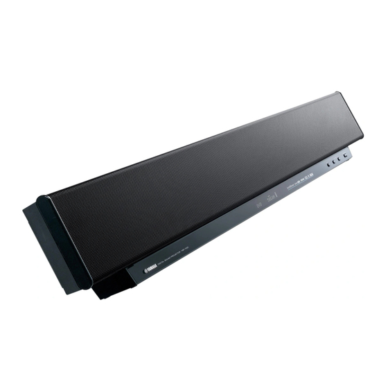
When transporting this unit, be sure to use the unit's packing materials and box so as to protect
it against any damage, in particular, dents in the front grille during transportation.
本機を輸送する場合、輸送時の破損 (特に、フロントグリルのへこみ) 等を防ぐために必ず専用の梱
包箱を使用してください。
This manual has been provided for the use of authorized YAMAHA Retailers and their service personnel.
It has been assumed that basic service procedures inherent to the industry, and more specifically YAMAHA Products, are already
known and understood by the users, and have therefore not been restated.
WARNING:
IMPORTANT:
The data provided is believed to be accurate and applicable to the unit(s) indicated on the cover. The research, engineering, and
service departments of YAMAHA are continually striving to improve YAMAHA products. Modifications are, therefore, inevitable
and specifications are subject to change without notice or obligation to retrofit. Should any discrepancy appear to exist, please
contact the distributor's Service Division.
WARNING:
IMPORTANT:
I CONTENTS
To Service Personnel .......................................... 2
FRONT PANEL .............................................................. 3
Rear Panels .............................................................. 3
Remote Control Panels ...................................... 4
SPECIFICATIONS / 参考仕様 ........................................ 5
Internal View ........................................................... 5
SET MENU TABLE / セットメニュー ............................ 6
SERVICE PRECAUTIONS / サービス時の注意事項 ..... 7
DISASSEMBLY PROCEDURES / 分解手順 ........... 7–13
ファームウェアの書き込み ..................................... 14–24
SELF DIAGNOSIS FUNCTION (DIAG) /
自己診断機能(ダイアグ) ..................................... 25–42
1 0 1 0 3 6
DIGITAL SOUND PROJECTOR
YSP-1100
Failure to follow appropriate service and safety procedures when servicing this product may result in personal
injury, destruction of expensive components, and failure of the product to perform as specified. For these reasons,
we advise all YAMAHA product owners that any service required should be performed by an authorized
YAMAHA Retailer or the appointed service representative.
The presentation or sale of this manual to any individual or firm does not constitute authorization, certification or
recognition of any applicable technical capabilities, or establish a principle-agent relationship of any form.
Static discharges can destroy expensive components. Discharge any static electricity your body may have
accumulated by grounding yourself to the ground buss in the unit (heavy gauge black wires connect to this buss).
Turn the unit OFF during disassembly and part replacement. Recheck all work before you apply power to the unit.
2006
This manual is copyrighted by YAMAHA and may not be copied or
redistributed either in print or electronically without permission.
SERVICE MANUAL
IMPORTANT NOTICE
Display Data ........................................................... 43
Ic Data ................................................................. 44–45
Block Diagrams .............................................. 46–47
Printed Circuit Boards................................ 48–58
Pin Connection Diagram .................................... 59
Schematic Diagrams ...................................... 61–68
Replacement Parts List .............................. 69–93
Remote Control .............................................. 94–95
拡張メニューを設定する ........................................ 96–98
All rights reserved.
P.O.Box 1, Hamamatsu, Japan
'06.08
Advertisement
Table of Contents

Related Manuals for Yamaha YSP-1100U


Summary of Contents for Yamaha YSP-1100U
- Page 1 This manual has been provided for the use of authorized YAMAHA Retailers and their service personnel. It has been assumed that basic service procedures inherent to the industry, and more specifically YAMAHA Products, are already known and understood by the users, and have therefore not been restated.
- Page 2 YSP-1100 I TO SERVICE PERSONNEL AC LEAKAGE WALL EQUIPMENT TESTER OR 1. Critical Components Information OUTLET UNDER TEST EQUIVALENT Components having special characteristics are marked s and must be replaced with parts having specifications equal to those originally installed. 2. Leakage Current Measurement (For 120V Models Only) When service has been completed, it is imperative to verify INSULATING that all exposed conductive surfaces are properly insulated...
- Page 3 YSP-1100 I FRONT PANEL J model I REAR PANELS (IR OUT) OPTIMIZER MIC U, C, T, K, A, B, G, E, L, V models J model BOTTOM VIEW U, C models T model K model A model B, G, E models L model V model J model...
- Page 4 YSP-1100 I REMOTE CONTROL PANELS U model C, T, K, A, B, G, E, L, V models J model...
- Page 5 Component video ............5 Hz-60 MHz 単位 : mm (インチ) I Speaker Section / スピーカー部 The “ ” logo and “IntelliBeam” are trademarks of YAMAHA Type / 型式 ..........2-way acoustic suspension Corporation. Magnetic shielding type 「インテリビーム」 「 IntelliBeam」 は、ヤマハ株式会社の登録商標です。...
- Page 6 YSP-1100...
- Page 7 YSP-1100 I SERVICE PRECAUTIONS / サービス時の注意事項 安全対策 Safety measures ・ この製品の内部には高電圧部分があり危険です。修理の • Some internal parts in this product contain high voltages and are dangerous. Be sure to take safety measures 際は、絶縁性の手袋を使用するなどの安全対策を行って ください。 during servicing, such as wearing insulating gloves. • Note that C523 on the INPUT (1) P.C.B. is dangerous ・...
- Page 8 YSP-1100 1. トップパネル、プレート/トップの外し方 1. Removal of Top Panels and Plate/Top a. Remove 8 screws (1). (Fig. 1) a. ①のネジ 8本を外します。 (Fig. 1) b. Remove 2 top panels. b. トップパネル 2個を取り外します。 c. ②のネジ 2本を外します。 (Fig. 1) c. Remove 2 screws (2). (Fig. 1) d.
- Page 9 YSP-1100 2. シールドユニットの外し方 2. Removal of Shield Unit a. 3 のネジ 22本を外します。 (Fig. 2) a. Remove 22 screws (3). (Fig. 2) b. Remove the rear panel. b. リアパネルを取り外します。 c. 4 のネジ 18本を外します。 (Fig. 3) c. Remove 18 screws (4). (Fig. 3) d.
- Page 10 YSP-1100 3. INPUT ( 1) 、 (2) P.C.B.の外し方 3. Removal of INPUT (1) and (2) P.C.B.s a. 5 のネジ 6本、 6 のネジ 8本、 7 のジャックスクリュー a. Remove 6 screws (5), 8 screws (6) and 2 jack screws (7). (Fig. 4) 2本を外します。...
- Page 11 YSP-1100 5. フロントパネルユニットの外し方 5. Removal of Front Panel Unit a. B のネジ 4本を外します。 (Fig. 6) a. Remove 4 screws (B). (Fig. 6) b. Remove 2 cover FPs. b. カバー FP 2個を外します。 c. コネクター CB3、CB303を外します。 (Fig. 6) c. Remove CB3 and CB303. (Fig. 6) d.
- Page 12 YSP-1100 Sound absorber 吸音材 Support/ DSP Support/ DSP C Support/ DSP サポート/ DSP サポート/ DSP C サポート/ DSP Fig. 9 Fig. 10 Installation of Driver (Tweeter) スピーカーユニット (ツイーター) の取り付け方 Caution : Make sure that all the removed driver (tweeter) 注意:取り外したスピーカーユニット (ツイーター) はすべ て決められた位置に取り付けてください。(Fig.
- Page 13 YSP-1100 8. スピーカーユニット (ウーファー) の外し方 8. Removal of Driver (Woofer) a. J のネジ 4本を外します。 (Fig. 11) a. Remove 4 screws (J). (Fig. 11) b. Remove the side covers L/R. b. サイドカバーL/Rを取り外します。 c. プレート/カバーを取り外します。 c. Remove the plate/cover. d. K のネジ 4本を外します。 (Fig. 11) d.
- Page 14 YSP-1100 I UPDATING FIRMWARE / ファームウェアーの書き込み After replacing the following parts with the replacement 下記の部品をサービス部品に交換した場合、ファームウェ アの書き込みを行ってください。 parts, update the firmware. P.C.B. DSPのIC11 : X8046B00 IC11 of P.C.B. ASS’Y DSP : X8046B00 ... Writing of DSP ... DSPの書き込み P.C.B. DSPのIC17 : X8045B00 IC17 of P.C.B.
- Page 15 YSP-1100 G Operation Procedure ● 操作方法 Writing of CPU CPUの書き込み 1. PCにDSP_FLASHER(YSP).exeをインストールしま 1. Install DSP_FLASHER(YSP).exe into the PC. す。 2. Before turning on the power to YSP-1100 and PC, con- nect between RS232C ports with the RS232C cable 2. YSP-1100とPCの電源を入れる前に、それぞれのRS232C ポート間をRS232Cケーブル...
- Page 16 YSP-1100 5. 送信データ、ポートを選択します。 5. Select the data to be transmitted and port. · MOT FILE ・ MOT FILE Select “SA25_vx.mot”. “SA25_vx.mot”を選択します。 ・ RS232C · RS232C Select the port of RS-232C. 接続しているRS-232Cポートを選択します。 Press this button to open the window このボタンを押すとウィンドウが開きます Select the firmware ファームウェアを選択します...
- Page 17 YSP-1100 7. プログラムの送信が終了すると、以下の画面が表示され 7. When the program transmission is completed, the screen appears as shown below. ます。 The press the [OK] button to end the procedure. [OK] ボタンを押して完了します。 8. Disconnect the power cable of YSP-1100 from the AC 8. YSP-1100の電源コードをACコンセントから抜きま す。...
- Page 18 YSP-1100 4.“YSP DSP” タグを選択します。 4. Select “YSP DSP” tag. 5. 送信データ、ポートを選択します。 5. Select the data to be transmitted and port. · DSP HEX FILE ・ DSP HEX FILE Select “YSPx00_verxxxx.hex”. “YSPx00_verxxxx.hex”を選択します。 ・ RS232C · RS232C Select the port of RS-232C. 接続しているRS-232Cポートを選択します。...
- Page 19 YSP-1100 7. YSP-1100の電源コードをACコンセントに接続し、 7. Connect the power cable of YSP-1100 to the AC outlet. While pressing the “VOL+” key and “VOL-” key of the YSP-1100の “VOL+” キーと “VOL-” キーを押しながら、 YSP-1100, press the “STANDBY/ON” key of the re- リモコンの “STANDBY/ON” キーを押し、ダイアグを起 動します。...
- Page 20 YSP-1100 9. SUM値を確認します。 9. Check the SUM. After downloading successfully, the value of “SUM from 書き込み完了後 “SUM from SET” が表示されます。 SET” is appeared. “SUM from FILE” と “SUM from SET” の値が同様になれ ば完了です。 The procedure is completed when the value is obtained for “SUM from FILE”...
- Page 21 3 Using the “ENTER” key of the remote control, make ③ リモコンの “ENTER” キーを使い、下図のように変更 します。 a change as shown below. Change YAMAHA to 1Ltd. YAMAHA → 1Ltd.に変更します 4 For restarting, use the “STANDBY/ON” key of the ④ YSP-1100またはリモコンの “STANDBY/ON” キーで...
- Page 22 YSP-1100 5. 送信データ、ポートを選択します。 5. Select the data to be transmitted and port. · COM Port ・COM Port Select the port of RS-232C. 接続しているRS-232Cポートを選択します。 ・D/load Protocol · D/load Protocol Select “SPCM protocol” SPCMプロトコルを選択します。 Select the port of RS-232C 接続しているRS-232Cポートを選択します Select SPCM protocol SPCMプロトコルを選択します...
- Page 23 YSP-1100 2 Software Target項目を確認し、 [Download] ボタン 2 Confirm Software Target and press the [Download] を押します。 button. Firm Software Target DSP application SPCM Application SPID SPCM init Data ※ Software Target項目は書き込みファイル選択時、 * When Source Filename is selected, Software Target box is selected automatically. 自動的に選択されます。...
- Page 24 3 Using the “RETURN” key of the remote control, ③ リモコンの “RETURN” キーを使い、下図のように変 make a change as shown below. 更します。 Change 1Ltd. to YAMAHA 1Ltd. → YAMAHAに変更します 4 Check the version of the firmware. ④ ファームウェアのバージョンを確認します。 リモコンの “LEFT” キーまたは “RIGHT” キーを使い、...
- Page 25 YSP-1100 I SELF DIAGNOSIS FUNCTION (DIAG) / 自己診断機能(ダイアグ) There are 14 DIAG menu items, each of which has sub- ダイアグメニューは1 4 個あり、そのそれぞれにサブメ ニューがあります。下表はメニュー一覧です。 menu items. Listed in the table below are menu items and sub-menu items. DIAG MENU SUB MENU DSP THROUGH 1.
- Page 26 YSP-1100 DIAG MENU SUB MENU 11. BS 2 12. BS 3 13. BS 4 14. BS 5 15. BS 6 16. BS 7 17. DS 1 18. DS 2 19. T 11 20. T 12 21. T 13 22. T 21 23.
- Page 27 YSP-1100 • Starting DIAG ● ダイアグの起動 To activate the DIAG function, press the “STANDBY/ON” 本体の下図に示すキーを同時に押しながらリモコンの key of the remote control while pressing the keys of the “STANDBY/ON” キーを押すと、ダイアグが起動します。 main unit as shown below at the same time. Keys of main unit / 本体キー...
- Page 28 YSP-1100 DIAGNOSTIC MENU 1.DSP THR 8.PRESET 2.RAM THR 9.AD CHECK 3.PRO LOGIC 10.IF STATUS 4.MIC CHECK 11.MODEL 5.VFD CHECK 12.VER/SUM 6.MAN’ LTEST 13.DATE 7.RS232C 14.DSP CHECK 本体のFLディスプレイにプロテクション履歴情報とバージョ The FL display of the main unit displays the protection function history data and the version (1 alphabet) and the ン...
- Page 29 YSP-1100 • History of protection function ● プロテクションの履歴 When the protection function has worked, its history is プロテクションが働いた場合、履歴をバックアップして stored in memory with a backup. Even if no abnormality 記憶しています。サービスのときに異常が認められなく is noted while servicing the unit, an abnormality which ても、バックアップが残っていれば、お客様のところで has occurred previously can be defined as long as the 起きた異常を区別できます。...
- Page 30 YSP-1100 • Details of DIAG menu ● ダイアグメニュー詳細 With full-bit output specified in some modes, it is possible 一部のモードでフルビット指定することで、各チャンネルの to execute 0dBFS output without head margin in each ヘッドマージンを廃して0dBFS出力することが可能です。 channel. 1. DSP THROUGH 1. DSP THROUGH ビーム化は行わず、サブメニューの指定CHから出力し The signal is not changed into beam and output from ます。...
- Page 31 YSP-1100 [ DD/dts/AAC multi ] OPT1 TI-DSP Ti-DSP OPT2 SL/SR SL/SR COAX C/LFE C/LFC LFE&BASS Analog1 YSS-930 YSS-930 YSS-930 Analog2 SWFR WFL/WFR TXn(beam) TXn(beam) TXn(beam) [ PCM ] OPT1 TI-DSP Ti-DSP OPT2 COAX L/LFC L&BASS Analog1 YSS-930 YSS-930 YSS-930 Analog2 SWFR TXn(beam) TXn(beam)
- Page 32 YSP-1100 2. RAM THROUGH 2. RAM THROUGH ビーム化は行わず、サブメニューの指定CHから出力し The signal is not changed into beam and output from ます。 the channel specified by the sub-menu. When 2CH signals are input, they are distributed as fol- 2CH信号入力時はDSP♯1にて以下のように信号を振り lows at DSP#1. 分けます。 L CH ..
- Page 33 YSP-1100 [ DD/dts/AAC multi ] OPT1 TI-DSP Ti-DSP OPT2 SL/SR SL/SR COAX C/LFE C/LFC LFE&BASS Analog1 YSS-930 YSS-930 YSS-930 Analog2 SWFR WFL/WFR TXn(beam) TXn(beam) TXn(beam) [ PCM ] OPT1 TI-DSP Ti-DSP OPT2 COAX L/LFC L&BASS Analog1 YSS-930 YSS-930 YSS-930 Analog2 SWFR TXn(beam) TXn(beam)
- Page 34 YSP-1100 3. PRO LOGIC / NEO6 3. PRO LOGIC / NEO6 PRO LOGIC I, II, Neo:6 can be selected from the sub- サブメニューでPRO LOGIC I、II、Neo:6を選択可能です。 menu items. PRO LOGIC I (PRO LOGIC EMULATION) PRO LOGIC I (PRO LOGIC EMULATION) PRO LOGIC II PRO LOGIC II Neo:6 Neo:6...
- Page 35 YSP-1100 5. DISPLAY CHECK 5. DISPLAY CHECK This program is used to check the FL display section. FL表示部のチェックプログラムです。サブメニュー操 The display condition varies as shown below according 作により、表示状態が以下のように変わります。 信号処理はEFFECT OFF (ANALOG MAIN BYPASSで to the sub-menu operation. The signals are processed using EFFECT OFF (The L/R signal is output using L/Rを出力)...
- Page 36 YSP-1100 6. MANUAL TEST 6. MANUAL TEST DSP内蔵のノイズ発生回路によって、サブメニューで指 The noise generator with a built-in DSP outputs the test 定したチャンネルへテストノイズを出力します。 noise through the channels specified by the sub-menu. LFE用のノイズ周波数は35∼250Hz、それ以外は中心周 The noise frequency for LFE is 35 to 250 Hz. Other than that, the center frequency is 800Hz.
- Page 37 YSP-1100 8. FACTORY PRESET 8. FACTORY PRESET This menu is used to reserve and inhibit initialization of バックアップ用RAM (音場プログラムのパラメーターや the back-up RAM. The signals are processed using セットメニュー内容等) の初期化を予約/禁止します。 信号処理はEFFECT OFFと同じです (ANALOG MAIN EFFECT OFF. (The L/R signal is output using ANALOG MAIN BYPASS.) BYPASSで、L/Rを出力)...
- Page 38 YSP-1100 10. IF STATUS 10. IF STATUS (Input function status) Using the sub-menu, the status data is displayed one サブメニュー操作により、以下のステータス情報を順次 after another in the hexadecimal notation. 16進数で表示します。信号処理は、本メニュー実行前 の状態を維持します。 During signal processing, the status before execution of this menu is maintained. ※...
- Page 39 YSP-1100 11. MODEL 11. MODEL The information on the model, destination and video モデル、仕向、ビデオフォーマットの情報を表示します。 format is displayed. MODEL SETTING MODEL SETTING DESTINATION DESTINATION J, UC, BGATL or KV is displayed. J、UC、BGATL、KVのいずれかを表示します。 VIDEO FORMAT VIDEO FORMAT NTSC (U, C, K, V, J models) NTSC (U、C、K、V、J models)...
- Page 40 YSP-1100 13. DATE 13. DATE There are 6 sub-menu items. サブメニューは6つあります。 The updated date of the program, clearance of the プログラムの更新日付、プロテクション履歴のクリア、 リモコン受信コードを表示します。 protection history and the remote control reception code are displayed. Remo Codeのメニューにすると、リモコンの全キーの 値を検出するためキー操作はできなくなりますが、本体 When Remo Code menu is selected, keys become non- の...
- Page 41 YSP-1100 14. DSP CHECK 14. DSP CHECK Tx Test Ch Tx Test Ch 各スピーカーユニットを鳴らし、不良・取付位置の確認を Have the sound produced from each driver to check its condition and installation position. します。 リモコンの “ENTER” キー、 “RETURN” キーを使って選択 Use the “ENTER” and “RETURN” keys of the remote します。...
- Page 42 YSP-1100 RS232C RS232C Select the protocol of RS-232C connection. RS-232C接続のプロトコルを選択します。 It select it at the time of writing IC17. / (IC17) 書き込み時選択します。 Cert Mode Cert Mode 試験用の特殊モードを選択します。 Select the special mode for testing. * Be sure to set to “OFF” ※...
- Page 43 YSP-1100 I DISPLAY DATA G V1 : 15-BT-99GNKF (WE204600) PATTERN AREA G PIN CONNECTION Pin No. Connection 24 23 22 21 20 19 Pin No. Connection P32 P33 P34 P35 NX NX Note : 1) F1, F2 ..Filament 2) NP ..No pin 3) NX ..
- Page 44 YSP-1100 I IC DATA IC26 : M30626FJPFP (DSP P.C.B) 16-bit Microprocessor Port P0 Port P1 Port P2 Port P3 Port P4 Port P5 Port P6 <VCC2 ports> <VCC1 ports> Internal peripheral functions A/D converter System clock (10 bits 8 channels generation circuit Timer (16-bit) Expandable up to 26 channels)
- Page 45 YSP-1100 IC26 : M30626FJPFP (DSP P.C.B) IC26 : M30626FJPFP (DSP P.C.B) 16-bit Microprocessor 16-bit Microprocessor Pin No. Port Definition Function Pin No. Name Definition Function PO96 Data output to FL driver Clock signal to EEPROM FL_TXD PO40 PO95 FL_CLK Clock output to FL driver PO37 Terminated PO94...
- Page 46 YSP-1100 I BLOCK DIAGRAMS AUDIO/VIDEO SECTION IC24 IC516 29,35 DRIVER YDA138 • See page 61-63 → WOOFER R DIGITAL SCHEMATIC DIAGRAM RMCK INPUT IC716 XTAL Woofer 24.576MHz 29,35 DRIVER YDA138 28,29 WOOFER L DVD (U,C,T,K,A, 2 7 24MT B,G,E,L,V models)/ 3 1 2 AUX (J model) IC12...
- Page 47 YSP-1100 POWER SUPPLY SECTION • See page 67 → • See page 66 → INPUT(1) INPUT(2) SCHEMATIC DIAGRAM SCHEMATIC DIAGRAM T502 D522 D510 TH501 MGND +12A SWITCHING D542 D528 POWER SUPPLY IC510 +12V C556 +5VA +5VA D523 IC509 C543 AGND A12V Q505 (+12A)
- Page 48 YSP-1100 I PRINTED CIRCUIT BOARDS DSP P.C.B. (Side A) INPUT (1) INPUT (2) INPUT (2) (CB508) (CB3) (CB2) AMP (2) (CB502) AMP (1) (CB702) DGND YASDO0 AGND YASDO1 DGND WFL_OUT YASDO2 AGND DGND YASDO3 D3_PROTN DGND /WF_MUTE YASDO4 YASDO5 D3_MUTEN D4_MOD0 DGND YABCK...
- Page 49 YSP-1100 DSP P.C.B. (Side B) • Semiconductor Location Ref. No. Location Ref. No. Location Ref. No. Location Ref. No. Location IC10 IC23 IC13 IC24 IC18 IC19 IC20 IC22...
- Page 50 YSP-1100 • Semiconductor Location Ref. No. Location Ref. No. Location Ref. No. Location Ref. No. Location Ref. No. Location D501 D507 IC502 IC510 Q501 D502 D508 IC503 IC512 Q502 AMP (2) P.C.B. (Side A) D503 D509 IC504 IC513 D504 D510 IC505 IC514 D505...
- Page 51 YSP-1100 • Semiconductor Location Ref. No. Location Ref. No. Location Ref. No. Location Ref. No. Location Ref. No. Location D701 D707 IC702 IC710 Q701 D702 D708 IC703 IC712 Q702 AMP (1) P.C.B. (Side A) D703 D709 IC704 IC713 D704 D710 IC705 IC714 D705...
- Page 52 YSP-1100 INPUT (1) P.C.B. (Side A) Circuit No. U, C, V, J T, K, A, B, G, E, L C501 X : NOT USED O : USED / APPLICABLE INPUT (2) (W505) AGND AC IN AGND +12A +5VA S3.3 +12B (W1) AGND AGND...
- Page 53 YSP-1100 INPUT (1) P.C.B. (Side B) • Semiconductor Location Ref. No. Location Ref. No. Location Ref. No. Location Ref. No. Location D502 D513 D527 D541 D504 D514 D529 IC505 D507 D519 D530 Q504 D508 D520 D532 D509 D521 D533 D512 D526 D540...
- Page 54 YSP-1100 INPUT (2) P.C.B. (Side A) OPTICAL AUDIO IN VIDEO IN VIDEO OUT RS-232C REMOTE IN COAXIAL TV/STB TV / STB SUBWOOFER DVD / AUX INPUT (1) (CB4) AGND AGND A12V +5VA S3.3 +12B (W3) • Semiconductor Location Ref. No. Location (W2) IC12 Circuit No.
- Page 55 YSP-1100 INPUT (2) P.C.B. (Side B) • Semiconductor Location Ref. No. Location Ref. No. Location Ref. No. Location Ref. No. Location Ref. No. Location IC15 IC10 IC11...
- Page 56 YSP-1100 INPUT (3) P.C.B. (Side A) INPUT (3) P.C.B. (Side B) OPERATION (4) (CB301) IR OUT • Semiconductor Location Ref. No. Location Ref. No. Location D401 D407 D402 D408 D403 IC401 D404 IC402 D405 Q401 D406 Q402...
- Page 57 YSP-1100 OPERATION (1) P.C.B. (Side A) (CB6) OPERATION (2) (W12) KEY0 KEY1 S3.3 STBY_SW FL DISPLAY OPERATION (1) P.C.B. (Side B) 32 33 • Semiconductor Location Ref. No. Location Ref. No. Location Ref. No. Location...
- Page 58 YSP-1100 • Semiconductor Location Ref. No. Location D801 D802 D803 D805 IC801 OPERATION (2) P.C.B. (Side A) OPERATION (2) P.C.B. (Side B) Q801 OPERATION (1) (CB3) OPERATION (3) P.C.B. (Side A) OPERATION (3) P.C.B. (Side B) OPTIMIZER INPUT OPERATION (4) (CB303) VOLUME- OPERATION (4) P.C.B.
- Page 59 YSP-1100 I PIN CONNECTION DIAGRAM • ICs • Diodes AN77L04 NJM78M05FA NJM2068MD-TE2 S-29630AFJA PLT421 PQ1CZ41H2Z 1Z180 1SS133 MA8036 SB01-05Q µPC4570G2 NJM78L09A-T3 1Z330 1SS355 MA8051-M NJM78M12FA AK09V0 1SS380 MA8062-M NJM2717M D1NL20U Anode RB501V-40 MA8068-M ERA22 UDZ5.1B MA8091-M Anode MTZJ27D MA8100-M MA8110-H MA8150-H Cathode 2: OUT...
- Page 60 YSP-1100 MEMO MEMO MEMO MEMO...
- Page 61 YSP-1100 SCHEMATIC DIAGRAMS DSP 1/3 IC9: W9816G6CH-7 POINT B-1 Pin 13 of IC26 512K x 2 banks x 16 bits SDRAM CLK 35 CLOCK BUFFER CKE 34 CONTROL COLUMN DECODER SIGNAL GENERATOR COMMAND DECODER CELL ARRAY 2 DQ0 BANK #0 3 DQ1 5 DQ2 A10 20...
- Page 62 YSP-1100 DSP 2/3 IC12: D60YA003BPYP225 Decoder Digital Signal Processors EMIF32 L2 Cache/ L1P Cache Memory 4 Banks Direct Mapped McASP1 64K Bytes 4K Bytes Total Total McASP0 (4-Way) C67x McBSP1 Instruction Fetch Control Registers McBSP0 Instruction Dispatch Control Instruction Decode Logic I2C1 Enhanced...
- Page 63 YSP-1100 DSP 3/3 IC18-20: YSS930-SZ MICROPROCESSOR INTERFACE PROGRAM COEFFICIENT ADDRESS CONTROL REGISTER 50 bit ✻ 1024 word 16 bit ✻ 1024 word 17 bit ✻ 256 word CONTROL SIGNALS SDBCK SDWCK SDI0 SDO0 SDI1 SDO1 SDI2 SDO2 SDI3 SDO3 32 bit DSP Core SDI4 SDO4 SDI5...
- Page 64 YSP-1100 DRIVER AMP 1/2 (WOOFER) Page 63 to DSP_CB8 No replacement part available. サービス部品供給なし Page 67 to INPUT (1)_CB504 AMP (2) DRIVER x 5 DRIVER x 5 DRIVER x 5 DRIVER x 5 IC516: YDA138 IC501, 502, 505, 506, 509, 510, 512-515: YDA139 (TWEETER) (TWEETER) (TWEETER)
- Page 65 YSP-1100 AMP 2/2 DRIVER (WOOFER) Page 63 to DSP_CB9 No replacement part available. サービス部品供給なし Page 67 to INPUT (1)_CB507 AMP (1) IC716: YDA138 IC701, 702, 705, 706, 709, 710, 712-715: YDA139 Digital audio power amplifier Digital audio power amplifier DRIVER x 5 DRIVER x 5 DRIVER x 5 DRIVER x 5...
- Page 66 YSP-1100 INPUT 1/2 12.0 POINT A-3 Pin 6 of IC10 INPUT SELECTOR 12.0 Page 63 to DSP_W3 IC2: BA7611AF-E2 IC9: NJM2257M Video signal switcher Synchronous signal separator MUTE CTLA CTLB LOGIC INPUT SELECTOR 12.0 12.0 IC6: NJM2585M 12.0 Wide band 3-input 1-output 3-circuit video amplifier 12.0 CH1 IN1 CH1 OUT...
- Page 67 YSP-1100 INPUT 2/2 Safety measures • Some internal parts in this product contain high voltages and are dangerous. Be sure to take safety measures during servicing, such as wearing insulating gloves. • Note that C523 is dangerous even after the power is turned off because an electric charge remains and a high voltage continues to exist there. Before starting any repair work, perform discharge by connecting a discharge resistor (5 k-ohms/10 W) between C523 terminals.
- Page 68 YSP-1100 OPERATION OPERATION (4) 12.0 OPTIMAIZER MIC Page 63 to DSP_CB7 Page 67 to INPUT (3)_W401 OPERATION (3) FL DISPLAY Page 63 to DSP_CB6 -24.1 -17.5 -17.8 12.0 -17.9 -22.5 -17.8 -22.5 -24.7 -17.8 -22.5 -17.8 -22.5 -16.2 -16.2 -22.5 -19.3 -24.1 -17.8...
- Page 69 YSP-1100 I REPLACEMENT PARTS LIST • ELECTRICAL COMPONENT PARTS WARNING G Components having special characteristics are marked s and must be replaced with parts having specifications equal to those originally installed. ● s印のある部分は、 安全確保部品を示 しています。 部品の交換が必要な場合、 パーツ リ ス トに記載されている部品を使用 して く ださい。 ●...
- Page 70 YSP-1100 P.C.B. DSP Ref No. Part No. Description Remarks Markets 部 品 名 Rank WH754000 P.C.B. PCB DSP VT388300 CN.BS.PIN ベース付ポスト WD736900 CN.BS.PIN 14P TE ベース付ポスト VT388700 CN.BS.PIN ベース付ポスト CB8-9 WC198000 CN.BS.PIN 30P TE FMNコネクター C1-3 WE477600 C.EL 100uF ケミコン C4-9 WD176300 C.CE.CHP 16V K チップセラコン...
- Page 71 YSP-1100 P.C.B. DSP Ref No. Part No. Description Remarks Markets 部 品 名 Rank C124 UF037100 C.EL.CHP 10uF チップケミコン C125 UF017220 C.EL.CHP 22uF 6.3V チップケミコン C126-128 US135100 C.CE.CHP 0.1uF チップセラコン C129-130 UF018100 C.EL.CHP 100uF 6.3V チップケミコン C131-153 US135100 C.CE.CHP 0.1uF チップセラコン C154 UF037100 C.EL.CHP 10uF チップケミコン...
- Page 72 YSP-1100 P.C.B. DSP and P.C.B. AMP Ref No. Part No. Description Remarks Markets 部 品 名 Rank C293 UF037100 C.EL.CHP 10uF チップケミコン C294 US064100 C.CE.CHP 0.01uF 50V B チップセラコン C295 US063100 C.CE.CHP 1000pF 50V B チップセラコン C296-297 US064100 C.CE.CHP 0.01uF 50V B チップセラコン...
- Page 73 YSP-1100 P.C.B. AMP Ref No. Part No. Description Remarks Markets 部 品 名 Rank CB512 VL845400 CN.BS.PIN ベース付ポスト CB702 WA545900 CN 30P TE FFC/FPCコネクタ 01 CB707 LB918030 CN.BS.PIN ベース付ポスト CB709 VL845500 CN.BS.PIN 11P TE ベース付ポスト CB710 VL845400 CN.BS.PIN ベース付ポスト CB711 VL845500 CN.BS.PIN 11P TE ベース付ポスト...
- Page 74 YSP-1100 P.C.B. AMP Ref No. Part No. Description Remarks Markets 部 品 名 Rank C571 US135100 C.CE.CHP 0.1uF チップセラコン C572 US126100 C.CE.CHP チップセラコン C575 US126100 C.CE.CHP チップセラコン C576 UR818220 C.EL 220uF 6.3V ケミコン C577 US126100 C.CE.CHP チップセラコン C578 UR818220 C.EL 220uF 6.3V ケミコン...
- Page 75 YSP-1100 P.C.B. AMP Ref No. Part No. Description Remarks Markets 部 品 名 Rank C727 UR818220 C.EL 220uF 6.3V ケミコン C729 UR837100 C.EL 10uF ケミコン C730 UR866100 C.EL ケミコン C731 US135100 C.CE.CHP 0.1uF チップセラコン C732 UR866100 C.EL ケミコン C733 US135100 C.CE.CHP 0.1uF チップセラコン...
- Page 76 YSP-1100 P.C.B. AMP and P.C.B. INPUT Ref No. Part No. Description Remarks Markets 部 品 名 Rank C819 US135100 C.CE.CHP 0.1uF チップセラコン C824 UR839100 C.EL 1000uF ケミコン C825 UR829100 C.EL 1000uF ケミコン C826-827 US145100 C.CE.CHP 0.1uF チップセラコン C828-829 US126100 C.CE.CHP チップセラコン D501-510 VT332900 DIODE 1SS355 ダイオード...
- Page 77 YSP-1100 P.C.B. INPUT Ref No. Part No. Description Remarks Markets 部 品 名 Rank CB504 LB932060 CN.BS.PIN ベースポスト CB507 LB932060 CN.BS.PIN ベースポスト CB508 VF283300 CN.BS.PIN コネクタベースポスト CB509 VG879900 CN.BS.PIN ベースピン C1-2 US064100 C.CE.CHP 0.01uF 50V B チップセラコン C3-4 US060800 C.CE.CHP 50V B チップセラコン...
- Page 78 YSP-1100 P.C.B. INPUT Ref No. Part No. Description Remarks Markets 部 品 名 Rank UR818100 C.EL 100uF 6.3V ケミコン US035100 C.CE.CHP 0.1uF 16V B チップセラコン US060800 C.CE.CHP 50V B JUCKV チップセラコン US060700 C.CE.CHP 50V B TABGEL チップセラコン US060700 C.CE.CHP 50V B チップセラコン US035100 C.CE.CHP 0.1uF 16V B...
- Page 79 YSP-1100 P.C.B. INPUT Ref No. Part No. Description Remarks Markets 部 品 名 Rank C523 WF411500 C.EL 820uF 200V ケミコン C523 WF411500 C.EL 820uF 200V JUCV ケミコン C523 WF709700 C.EL 220uF 400V TKABGEL ケミコン C524 UR867100 C.EL 10uF ケミコン C525-526 US065100 C.CE.CHP 0.1uF 50V B チップセラコン...
- Page 80 YSP-1100 P.C.B. INPUT Ref No. Part No. Description Remarks Markets 部 品 名 Rank D527 VU999200 DIODE.ZENR MA8240-H 25V ツェナーダイオード D528 VQ052600 DIODE AK09V0 90V0.7A TP2 ダイオード D529-530 VT332900 DIODE 1SS355 ダイオード D531 VG443100 DIODE.ZENR MTZJ27D ツェナーダイオード D532 VU995900 DIODE.ZENR MA8110-H 11.3V ツェナーダイオード...
- Page 81 YSP-1100 P.C.B. INPUT and P.C.B. OPERATION Ref No. Part No. Description Remarks Markets 部 品 名 Rank Q505 WF871800 FET 2SK3876-01R TKABGEL FET Q506 WF764000 TR 2SA2093 Q TP トランジスタ HV753220 R.CAR.FP 2.2Ω 1/4W 不燃化カーボン抵抗 HV754150 R.CAR.FP 15Ω 1/4W 不燃化カーボン抵抗 HV754150 R.CAR.FP 15Ω...
- Page 82 YSP-1100 P.C.B. OPERATION Ref No. Part No. Description Remarks Markets 部 品 名 Rank UR818100 C.EL 100uF 6.3V ケミコン US065100 C.CE.CHP 0.1uF 50V B チップセラコン UR867100 C.EL 10uF ケミコン C104 UR857470 C.EL 47uF ケミコン C105 US065100 C.CE.CHP 0.1uF 50V B チップセラコン C301-305 US064100 C.CE.CHP 0.01uF 50V B チップセラコン...
- Page 83 YSP-1100 Chip Resistors The chip resistor is not supplied as a replacement part. ● チッ プ抵抗はサービス部品と して供給 しません。 * When a chip resistor is necessary, use the following part. ※ チッ プ抵抗が必要な場合は、 下記の部品をご利用く ださい。 AAX60720: CHIP RESISTOR SAMPLE BOOK AAX60720: CHIP RESISTOR SAMPLE BOOK Ref No.
- Page 84 YSP-1100 Chip Resistors Ref No. Part No. Description Remarks Markets 部 品 名 Rank R.CHP 100KΩ 1/16W J チップ抵抗 R.CHP 120KΩ 1/16W J チップ抵抗 R.CHP 220KΩ 1/16W J チップ抵抗 R.CHP 270KΩ 1/16W J チップ抵抗 R.CHP 470KΩ 1/16W J チップ抵抗 R.CHP 560KΩ 1/16W J チップ抵抗...
- Page 85 YSP-1100 Carbon Resistors Value 1/4W Type Part No. 1/6W Type Part No. Value 1/4W Type Part No. 1/6W Type Part No. 1.0 Ω 3100 3100 10 kΩ 7100 7100 HJ35 HF85 HF45 HF45 1.8 Ω ❊ 3180 11 kΩ 7110 7110 HJ35 HF45...
- Page 86 YSP-1100 • OVERALL ASS’Y 3-105 3-15 3-112 3-106 3-105 3-57 3-41 3-101 3-106 3-106 3-105 3-106 3-106 3-106 3-31 3-35 3-101 3-103 3-110 3-50 3-53 3-101 1-104 1-56 1-15 1-52 MAIN UNIT 1-45 1-104 1-52 1-104 1-41 1-31 1-51 1-32 1-41...
- Page 87 YSP-1100 Ref No. Part No. Description Remarks Markets 部 品 名 Rank 1-15 WE981400 CUSHION 90x40 クッション 1-31 WH736000 FRONT PANEL ASS'Y フロントパネルASSY 1-31 WH736100 FRONT PANEL ASS'Y UCTKABGELV フロントパネルASSY 1-32 WD833200 BUTTON ボタン 1-41 WE203500 レッグ 1-45 V6034100 EMBLEM エンブレム 1-51 WE203200 PACKING A パッキン A...
- Page 88 YSP-1100 • ACCESSORIES 300-1 308 x 4 Ref No. Part No. Description Remarks Markets 部 品 名 Rank ACCESSORIES 付属品 WJ210500 REMOTE CONTROL リモコン WJ210600 REMOTE CONTROL リモコン WJ210700 REMOTE CONTROL CTKABGELV リモコン 300-1 AAX57560 BATTERY COVER 103RRS-141-07L 電池蓋 s 302 WG305200 POWER CABLE 2m 1pc 電源コード...
- Page 89 YSP-1100 • PACKING ASS’Y Front Front 2 1 pair Ref No. Part No. Description Remarks Markets 部 品 名 Rank PACKING ASS'Y 梱包用部品 WH755100 CARTON BOX 梱包箱 WH755200 CARTON BOX UCTKABGELV 梱包箱 WG344700 POLYSTYRENE FOAM PAD 1pair スチロールパッド WG344800 POLYURETHANE PAD ウレタンパッド WG345200 CARTON SHEET ダンボールシート...
- Page 90 YSP-1100 • MAIN UNIT 2-103 2-75 2-103 2-21 2-111 2-111 2-75 2-77 2-21 2-103 2-103 2-77 2-51 2-105 2-103 2-51 2-105 2-103 2-11 2-105 2-105 2-105 2-11 2-103 (2) Rch 2-103 2-103 2-105 2-103 2-103 2-28 2-101 2-59 2-103 2-28 2-103 2-59 2-103...
- Page 91 YSP-1100 Ref No. Part No. Description Remarks Markets 部 品 名 Rank MAIN UNIT メインユニット WG114800 P.C.B. ASS'Y PCB AMP WH754000 P.C.B. ASS'Y PCB DSP 2-11 WG167600 FLEXIBLE FLAT CABLE 30P 50mm P=1.0 カード電線 2-13 WD397500 BINDING TIE MSF-085 束線止め 2-15 WF536700 FRONT GRILLE フロントグリル...
- Page 92 YSP-1100 • SUB CHASSIS UNIT 2-1-55 2-1-103 2-1-53 2-1-106 2-1-103 2-1-31 2-1-12 2-1-59 2-1-102 2-1-59 2-1-51 2-1-54 2-1-60 2-1-52 2-1-51 2-1-106 Silver color model 2-1-111 2-1-65 2-1-52 2-1-52 2-1-55 2-1-103 2-1-65 2-1-103 2-1-11 2-1-56 2-1-65 2-1-33 2-1-56 2-1-108 Black color model 2-1-101 2-1-65 2-1-103...
- Page 93 YSP-1100 Ref No. Part No. Description Remarks Markets 部 品 名 Rank SUB CHASSIS UNIT サブシャーシユニット 2-1-11 X7213A00 DRIVER WOOFER 11cm 4Ω スピーカーユニット 2-1-12 AAX75450 DRIVER TWEETER 4cm 4Ω スピーカーユニット 2-1-12 AAX75460 DRIVER TWEETER 4cm 4Ω UCTKABGELV スピーカーユニット 2-1-25 WF538600 GRILLE SPEAKER ASS'Y グリルSP ASSY...
- Page 94 YSP-1100 I REMOTE CONTROL • SCHEMATIC DIAGRAM DTA113ZKA 6.8ohms DTC144EKA IC2 1pin IC3 3pin 22k-ohms 1000µF 2.2mF 6.3V 5.5V (for BU) MIE-544A2 2ohms (1/4W) 16 24 32 40 48 56 27ohms 2SD1781K 15 23 31 39 47 14 22 30 38 46 54 13 21 29 37 45 12 20 28 36 44 52 11 19 27 35 43 51...
- Page 95 YSP-1100 • PANELS • KEY CODE Function U model Key Layout Key no. Code U, C, T, K, A, B, G, E, L, V models J model ー – – – ー – ー – – – ー – チューナー 78-DF ビデオ...
- Page 96 YSP-1100...
- Page 97 YSP-1100...
- Page 98 YSP-1100 YSP-1100...