Table of Contents
Advertisement
Quick Links
Advertisement
Table of Contents
Troubleshooting

Related Manuals for Mitsubishi Electric GT1695M-XTBD


Summary of Contents for Mitsubishi Electric GT1695M-XTBD
-
Page 3: Safety Precautions
SAFETY PRECAUTIONS (Always read these precautions before using this equipment.) Before using this product, please read this manual and the relevant manuals introduced in this manual carefully and pay full attention to safety to handle the product correctly. The precautions given in this manual are concerned with this product. In this manual, the safety precautions are ranked as "DANGER"... - Page 4 [DESIGN PRECAUTIONS] DANGER Incorrect operation of the touch switch(s) may lead to a serious accident if the GOT backlight is gone out. When the GOT backlight goes out, the POWER LED flickers (green/orange) and the display section turns black and causes the monitor screen to appear blank, while the input of the touch switch(s) remains active.
- Page 5 [MOUNTING PRECAUTIONS] CAUTION Use the GOT in the environment that satisfies the general specifications described in this manual. Not doing so can cause an electric shock, fire, malfunction or product damage or deterioration. When mounting the GOT to the control panel, tighten the mounting screws in the specified torque range.
- Page 6 [WIRING PRECAUTIONS] DANGER Be sure to shut off all phases of the external power supply used by the system before wiring. Failure to do so may result in an electric shock, product damage or malfunctions. CAUTION Always ground the FG terminal, LG terminal, and protective ground terminal of the GOT power to the protective ground conductors dedicated to the GOT.
- Page 7 [TEST OPERATION PRECAUTIONS] DANGER Before performing the test operations of the user creation monitor screen (such as turning ON or OFF bit device, changing the word device current value, changing the settings or current values of the timer or counter, and changing the buffer memory current value), read through the manual carefully and make yourself familiar with the operation method.
- Page 8 [STARTUP/MAINTENANCE PRECAUTIONS] CAUTION Do not disassemble or modify the unit. Doing so can cause a failure, malfunction, injury or fire. Do not touch the conductive and electronic parts of the unit directly. Doing so can cause a unit malfunction or failure. The cables connected to the unit must be run in ducts or clamped.
- Page 9 [BACKLIGHT REPLACEMENT PRECAUTIONS] CAUTION Wear gloves for the backlight replacement when using the GOT with the backlight replaceable by the user. Not doing so can cause an injury. Before replacing a backlight, allow 5 minutes or more after turning off the GOT when using the GOT with the backlight replaceable by the user.
-
Page 10: Revisions
This manual confers no industrial property rights or any rights of any other kind, nor does it confer any patent licenses. Mitsubishi Electric Corporation cannot be held responsible for any problems involving industrial property rights which may occur as a result of using the contents noted in this manual. -
Page 11: Table Of Contents
INTRODUCTION Thank you for choosing the Mitsubishi Graphic Operation Terminal. Before using the equipment, please read this manual carefully to use the equipment to its optimum. CONTENTS SAFETY PRECAUTIONS .............A - 1 REVISIONS . - Page 12 5. INSTALLATION 5 - 1 to 5 - 8 Control Panel Inside Dimensions for Mounting GOT 5 - 1 Panel Cutting Dimensions 5 - 2 Mounting Position 5 - 3 Control Panel Inside Temperature and Mounting Angle 5 - 7 Installation Procedure 5 - 7 6.
- Page 13 Utility Display 8 - 5 8.3.1 Display operation of main menu ..........8 - 7 8.3.2 Utility basic configuration .
- Page 14 11.2.2 Backup/restoration setting ..........11 - 6 11.2.3 Trigger backup settings .
- Page 15 14.2 Prior Preparations for Installing BootOS and Standard Monitor OS 14 - 3 14.3 BootOS and Standard Monitor OS Installation Using CF Card or USB Memory 14 - 4 14.3.1 Installing when starting the GOT ..........14 - 5 14.3.2 Installing using the data control function (Utility) .
-
Page 16: About Manuals
ABOUT MANUALS The following manuals are also related to this product. In necessary, order them by quoting the details in the tables below. The manual in PDF-format is included in the GT Works2 and GT Designer2 products. Related Manuals Manual Number Manual Name (Model Code) GT SoftGOT1000 Version2 Operating Manual... -
Page 17: Abbreviations And Generic Terms
Abbreviations and generic terms used in this manual are as follows: Abbreviations and generic terms Description GT SoftGOT1000 Abbreviation of GT SoftGOT1000 GT1695 GT1695M-X Abbreviation of GT1695M-XTBA, GT1695M-XTBD GT1685 GT1685M-S Abbreviation of GT1685M-STBA, GT1685M-STBD Abbreviation of GT1695, GT1685 GT16 , GT16... - Page 18 Communication unit Abbreviations and generic terms Description GT15-QBUS, GT15-QBUS2, GT15-ABUS, GT15-ABUS2, Bus connection unit GT15-75QBUSL, GT15-75QBUS2L, GT15-75ABUSL, GT15-75ABUS2L Serial communication unit GT15-RS2-9P, GT15-RS4-9S, GT15-RS4-TE RS-422 conversion unit GT15-RS2T4-9P, GT15-RS2T4-25P Ethernet communication unit GT15-J71E71-100 MELSECNET/H communication unit GT15-J71LP23-25, GT15-J71BR13 MELSECNET/10 communication unit GT15-75J71LP23-Z , GT15-75J71BR13-Z CC-Link IE controller network communication...
- Page 19 Option Abbreviations and generic terms Description GT05-MEM-16MC, GT05-MEM-32MC, GT05-MEM-64MC, GT05-MEM-128MC, Memory card CF card GT05-MEM-256MC Memory card adaptor GT05-MEM-ADPC GT16-MESB, GT15-FNB, GT15-QFNB, GT15-QFNB16M, Option function board GT15-QFNB32M, GT15-QFNB48M, GT15-MESB48M, GT11-50FNB Battery GT15-BAT, GT11-50BAT GT16-90PSCB, GT16-90PSGB, GT16-90PSCW, GT16-90PSGW, GT16-80PSCB, GT16-80PSGB, GT16-80PSCW, GT16-80PSGW, GT15-90PSCB, GT15-90PSGB,...
- Page 20 License key (for GT SoftGOT1000) Abbreviations and generic terms Description License GT15-SGTKEY-U, GT15-SGTKEY-P License key (for GT SoftGOT2) Abbreviations and generic terms Description License key A9GTSOFT-LKEY-P (For DOS/V PC) License key FD SW5D5F-SGLKEY-J (For PC CPU module) Others Abbreviations and generic terms Description OMRON PLC Abbreviation of PLC manufactured by OMRON Corporation...
-
Page 21: How To Use This Manual
HOW TO USE THIS MANUAL Functions This manual describes functions available for the GT Designer2 Version2.90U. For the added functions by the product version upgrade, refer to the list of functions added by GT Desiger2 version upgrade in Appendices. Symbols Following symbols are used in this manual Indicates the operation steps. -
Page 22: Packing List
PACKING LIST After unpacking, confirm that the following parts are included. Model Product Quantity GT1695M-X Battery Installation fitting GT16 General Description GT1685M-S Battery Installation fitting GT16 General Description - 20... -
Page 23: Overview
OVERVIEW About GOT GOT is installed on the panel surface of control panel or operating panel and connects to the PLC in the control panel. GOT carries out switch operation, lamp display, data display, and message display etc. Connector for program For display screen, two kinds of display screens, user-created screen and utility screen are available. - Page 24 About Manual The following manuals related to GOT1000 series are available. Refer to each manual in accordance with the intended use. Stored in the GT Works2/GT Designer2 in PDF format. (1) Installation of the software programs Drawing Data transfer For operations from creating project data to transferring data to GOT, refer to the following manuals.
- Page 25 (2) Installing a GOT Connecting to a controller For the operations from installing a GOT to communicating with a controller, refer to the following manuals. (Included) GOT1000 Series GT16 General Purpose GT16 User's Manual Description Connection Manual Confirming part names and Overview specifications of the GOT Detailed...
-
Page 26: Features
1.1 Features (1) Improved monitoring performance and connectivity to FA devices • Using of TFT color liquid crystal display (high intensity, wide angle view and high definition type) provides clear full-color display and displays small characters clearly. (Displays digital images of BMP and other formats in 65536 colors.) •... -
Page 27: Rough Pre-Operation Procedure
1.2 Rough Pre-operation Procedure The outline procedure before operating GOT is shown. Start Install GT Designer2 in the PC. Refer to GT Designer2 Version Basic Operation/Data Transfer Manual Create project data. Refer to GT Designer2 Version Screen Design Manual 6. WIRING) Wire for the GOT power supply. - Page 28 By connecting with the Ethernet interface included as standard in GT 16, project data can be downloaded/ uploaded. For download/upload of project data with the Ethernet connection, BootOS and standard monitor OS should be installed in the GOT in advance so that the GOT and PC can communicate with each other via Ethernet by setting Communication Settings.
-
Page 29: System Configuration
SYSTEM CONFIGURATION 2.1 Overall Configuration The overall configuration of GOT is as follows. For the connection methods applicable to GOT1000 series and cable, refer to the following. GOT1000 Series Connection Manual Refer to Protective sheet 7.3.1 Refer to Extension unit Refer to Protective cover for oil 7.3.1... - Page 30 2.2 Component List (1) Explanation of the GOT model name G T 1 6 Power type : 100 to 240VAC : 24VDC : Black Panel color type Display device type : TFT color (High intensity, Wide angle view) Resolution : 1024 768 (XGA) : 800 600 (SVGA)
-
Page 31: Component List
(3) Third party PLC connection cable G T 0 9 P: Plug (male) Connector pin type of the S: Socket (female) connection target T: Solderless terminal (For third party PLC side) C: Preparatory soldering Number of connector pins (Indicates the number of terminals for solderless or preparatory-soldered terminals.) Cable distinction numbers for one manufacturer's products... -
Page 32: Got
65536 colors, video/RGB, multimedia compliant, 100 to 240VAC, Memory size 15MB 15" (1024 768 dots), TFT color liquid crystal, (high intensity, wide angle view), GT1695M-XTBD 65536 colors, video/RGB, multimedia compliant, 24VDC, Memory size 15MB 12.1" (800 600 dots), TFT color liquid crystal, (high intensity, wide angle view),... -
Page 33: Option
2.2.2 Option Communication unit (Sold separately) Product name Model name Description For last GOT, Number of IN side GT15-QBUS connectors: 1 For QCPU (Q Mode)/Motion controller CPU (Q Series) For intermediary and last GOT, connection (standard model) GT15-QBUS2 Number of IN and OUT side connectors: 1 for each side For last GOT, Number of IN side GT15-ABUS... - Page 34 QCPU (Q Mode) bus connection cable (Sold separately) Product name Model name Description GT15-QC06B Cable length 0.6m GT15-QC12B Cable length 1.2m Q extension cable For connecting QCPU and GOT GOT-to-GOT GT15-QC30B Cable length 3m For connecting GOT and GOT connection cable GT15-QC50B Cable length 5m GT15-QC100B...
- Page 35 Product name Model name Description GT15-C07BS Cable length 0.7m GT15-C12BS Cable length 1.2m GOT-to-GOT connection cable GT15-C30BS Cable length 3m GT15-C50BS Cable length 5m For connecting GOT and GOT GT15-C100BS Cable length 10m GOT-to-GOT long distance connection GT15-C200BS Cable length 20m cable GT15-C300BS Cable length 30m...
- Page 36 Product name Model name Description GT01-C10R4-8P Cable length 1m FXCPU direct GT01-C30R4-8P Cable length 3m For connecting FXCPU (MINI DIN 8 pins connection cable, connector) and GOT FX communication GT01-C100R4-8P Cable length 10m For connecting FXCPU communication function extension function extension board (MINI DIN 8 pins board connection connector) and GOT GT01-C200R4-8P...
- Page 37 Product Model name Description name GT09-C30R40101-9P Cable length 3m GT09-C100R40101-9P Cable length 10m For connecting GOT to OMRON PLC, serial communication module, serial communication board GT09-C200R40101-9P Cable length 20m GT09-C300R40101-9P Cable length 30m GT09-C30R40102-9P Cable length 3m GT09-C100R40102-9P Cable length 10m RS-422 For connecting GOT to OMRON rack type host link unit, cable...
- Page 38 Connection cables for JTEKT PLCs (Sold separately) Product Model name Description name RS-232 GT09-C30R21201-25P Cable length 3 m For connecting GOT to JTEKT PLC cable GT09-C30R41201-6C Cable length 3 m GT09-C100R41201-6C Cable length 10 m RS-422 For connecting GOT to JTEKT PLC cable GT09-C200R41201-6C Cable length 20 m...
- Page 39 Connection cables for HITACHI PLCs (Sold separately) Product Model name Description name RS-232 For connecting GOT to HITACHI communication module GT09-C30R21301-9S Cable length 3m Cable (LQE560/LQE060/LQE160) GT09-C30R41301-9S Cable length 3m GT09-C100R41301-9S Cable length 10m RS-422 For connecting GOT to HITACHI PLC (LPQ510) and Cable communication module (LQE565/LQE165) GT09-C200R41301-9S...
- Page 40 Connection cables for YASKAWA PLCs (Sold separately) Product Model name Description name GT09-C30R20201-9P Cable length 3m GT09-C30R20202-15P Cable length 3m For connecting GOT to YASKAWA PLC RS-232 GT09-C30R20203-9P Cable length 3m cable GT09-C30R20204-14P Cable length 3m GT09-C30R20205-25P Cable length 3m For connecting GOT to YASKAWA MEMOBUS module GT09-C30R40201-9P Cable length 3m...
- Page 41 Connection cables for ALLEN-BRADLEY PLCs (Sold separately) Product Model name Description name RS-232 GT09-C30R20701-9S Cable length 3m For connecting GOT to ALLEN-BRADLEY PLC cable Connection cables for SIEMENS PLCs (Sold separately) Product Model name Description name RS-232 GT09-C30R20801-9S Cable length 3m For connecting GOT to SIEMENS HMI Adapter cable RS-422 connector conversion cable (Sold separately)
- Page 42 CF card (Sold separately) Product name Model name Description GT05-MEM-16MC Flash ROM 16MB GT05-MEM-32MC Flash ROM 32MB GT05-MEM-64MC Flash ROM 64MB CF card GT05-MEM-128MC Flash ROM 128MB GT05-MEM-256MC Flash ROM 256MB Commercially-available CF card Some models with the operations checked by our company are usable. For the operation-checked models, refer to "List of valid devices applicable for GOT1000 series"...
- Page 43 Option unit (Sold separately) Product name Model name Description Video input unit GT16M-V4 For video input signal (NTSC format / PAL format) 4 channels RGB input unit GT16M-R2 For analog RGB input signal 2 channels For video input signal (NTSC format / PAL format) 4 channels/analog Video/RGB input unit GT16M-V4R1 RGB input signal 1 channels mixed input...
- Page 44 Protective cover for oil (Sold separately) Product name Model name Description GT05-90PCO For 15" GOT Protective cover for GT05-80PCO For 12.1" GOT Backlight (Sold separately) Product name Model name Description GT16-90XLTT For 15" high intensity, wide angle view TFT (XGA) GT1695M-X Backlight GT16-80SLTT...
-
Page 45: Specifications
SPECIFICATIONS 3.1 General Specifications Item Specifications Display section 0 to 50°C Operating ambient Other than the 0 to 55°C temperature display section Storage ambient temperature -20 to 60°C Operating ambient humidity 10 to 90% RH, non-condensing Storage ambient humidity 10 to 90% RH, non-condensing Half- Frequency Acceleration... -
Page 46: Performance Specifications
The performance specifications of the GT16 is as follows. 3.2.1 GT1695M-X 3.2.2 GT1685M-S 3.2.1 GT1695M-X Specifications Item GT1695M-XTBA GT1695M-XTBD Type TFT color liquid crystal display (High intensity and wide angle view) Screen size 15" Resolution 1,024 768 dots Display size 304.1(12.0)(W) - Page 47 Specifications Item GT1695M-XTBA GT1695M-XTBD Detection length 1(39.37) [m](inch) Detection range Left/Right/Top/Bottom: 70 degrees Human sensor Detection delay time 0 to 4s Detection temperature Temperature difference between human body and ambient air: 4°C or higher C drive Built-in flash memory 15Mbytes (for storing project data and OS)
- Page 48 Specifications Item GT1695M-XTBA GT1695M-XTBD Compatible software package 2.90U or later (GT Designer2 Version) Bright dots (always lit) and dark dots (unlit) may appear on a liquid crystal display panel due to its characteristics. It is impossible to completely avoid this symptom, as the liquid crystal display comprises of a great number of display elements.
-
Page 49: Gt1685M-S
3.2.2 GT1685M-S Specifications Item GT1685M-STBA GT1685M-STBD Type TFT color liquid crystal display (High intensity and wide angle view) Screen size 12.1” Resolution 600 dots Display size 246(9.69)(W) 184.5(7.26)(H) [mm](inch) 16-dot standard font: 50 characters 37 lines (2byte character) Display character 12-dot standard font: 66 characters 50 lines (2byte character) Display... - Page 50 Specifications Item GT1685M-STBA GT1685M-STBD RS-232, 1ch Transmission speed: 15,200/57,600/38,400/19,200/9,600/4,800 bps Connector shape: D-sub 9-pin (Male) RS-232 Application: For communicating with a controller or connecting a personal computer (Project data upload/download, OS installation, FA transparent function) RS-422/485, 1ch Transmission speed: 115,200/57,600/38,400/19,200/9,600/4,800 bps RS-422/485 Connector shape: 14-pin (female) Application: For communicating with a controller.
- Page 51 Compliant with IP67 (JEM1030) when the USB environmental protection cover is attached with the part of the cover firmly pushed into. (Compliant with IP2X (JEM1030) at the USB interface when a USB cable or USB memory is connected.) Note that this does not guarantee all users' operation environment. In addition, the GOT may not be available for use in the environment where oil or chemicals are splashed over for a long period or where oil mist is filled.
-
Page 52: Power Supply Specifications
3.3 Power Supply Specifications The following describes the power supply specifications for the GT16. 3.3.1 For GOTs powered from the 100 to 240VAC power supply 3.3.2 For GOTs powered from the 24VDC power supply Remark Operation at momentary failure • If an instantaneous power failure occurs in the power supply and continues for more than the permissible period, the GOT will be reset. -
Page 53: For Gots Powered From The 24Vdc Power Supply
3.3.2 For GOTs powered from the 24VDC power supply Specifications Item GT1695M-XTBD GT1685M-STBD Input power 24VDC (+25%, -20%) supply voltage Power 60W or less 40W or less consumption At backlight 30W or less 26W or less Inrush current 12A or less (75ms) (maximum load) -
Page 54: Battery Specifications
3.4 Battery Specifications Battery specifications The following describes the battery specifications for the GT16. Item Specifications Type Magnesium manganese dioxide lithium primary battery Initial voltage 3.0V Nominal current 1800mAh Storage life Approx.5 years (Operating ambient temperature of 25°C) Total power stoppage time Refer to This Section Battery life Lithium content... -
Page 55: Part Name And Settings
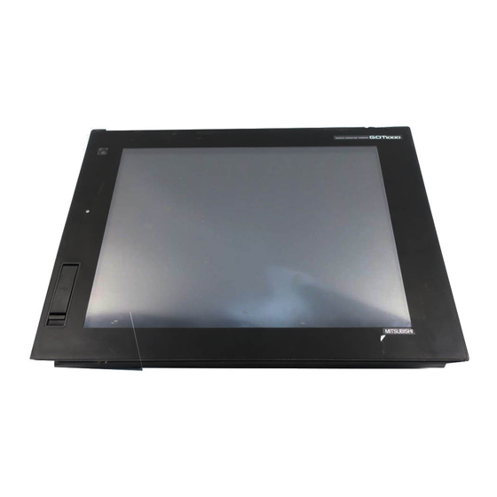
PART NAME AND SETTINGS 4.1 Part Names and Settings of the GT1695 2), 3) 20) 18) 16) 15) 4.1 Part Names and Settings of the GT1695... - Page 56 Name Description Lit in green : Power is correctly supplied Lit in orange : Screen saving 1) POWER LED Blinks in orange/green : Blown back light bulb Not lit : Power is not supplied 2) Display screen Displays the Utility and the user creation screen. 3) Touch key For operating the touch switches in the Utility and the user creation screen For connecting a personal computer...
- Page 57 Remark Connector used for the RS-232 interface The specification of the connector used for the RS-232 interface of GT1695 is as follows. Manufacturer :DDK Ltd. Model name :17LE-23090-27 (D4CK) or equivalent product Connector used for the RS-422/485 interface The specification of the connector used for the RS-422/485 interface of GT1695 is as follows.
-
Page 58: Part Names And Settings Of The Gt1685
4.2 Part Names and Settings of the GT1685 2), 3) 16)15) 4.2 Part Names and Settings of the GT1685... - Page 59 Name Description Lit in green : Power is correctly supplied Lit in orange : Screen saving 1) POWER LED Blinks in orange/green : Blown back light bulb Not lit : Power is not supplied 2) Display screen Displays the Utility and the user creation screen. 3) Touch key For operating the touch switches in the Utility and the user creation screen For connecting a personal computer...
- Page 60 Remark Connector used for the RS-232 interface The specification of the connector used for the RS-232 interface of GT1685 is as follows. Manufacturer :DDK Ltd. Model name :17LE-23090-27 (D4CK) or equivalent product Connector used for the RS-422/485 interface The specification of the connector used for the RS-422/485 interface of GT1685 is as follows.
-
Page 61: Control Panel Inside Dimensions For Mounting Got
INSTALLATION CAUTION Use the GOT in the environment that satisfies the general specifications described in this manual. Do not expose the GOT to dust, lamp soot, conductive dust, corrosive gas, or combustible gas; high-temperature, condensing, wind or rain; or to vibrations and impact. Failure to do so can cause an electric shock, fire, malfunction or product damage or deterioration. -
Page 62: Panel Cutting Dimensions
5.2 Panel Cutting Dimensions (1) Panel cutting dimensions when installing GOT Make a installation hole on the control panel with the dimensions shown below. Make space of 10mm above and below the hole respectively for the installation fittings. * Panel thickness: 2 to 4 mm or less A [mm] (inch) B [mm] (inch) 383.5(15.1) -
Page 63: Mounting Position
5.3 Mounting Position For installing GOT When mounting the GOT, the following clearances must be left from the other device. Some cables may need to be longer than the specified dimensions when connecting to the GOT. Therefore, consider the connector dimensions and bending radius of the cable as well for installation. For the lead-in allowance for cables at the bottom of the GOT, refer to the following. - Page 64 Type GT1695 GT1685 GOT only Bus connection unit is fitted 50(1.97) or more [20(0.79) or more] Serial communication unit fitted RS-422 Conversion unit is fitted 50(1.97) or more 51(2.01) or more CC-Link communication 50 (1.97) or more [20 (0.79) or more] unit (GT15-J61BT13) fitted MELSECNET/H communication unit 50 (1.97) or more [20 (0.79) or more]...
- Page 65 For installing CF card extension unit (1) Installing location (a) Depth dimensions When the control panel side installation unit is installed on the control panel, 180mm in depth (including the bending radius of the cable) is required inside the control panel. 180 or more (7.09) Unit : mm (inch)
- Page 66 (2) Prohibited area for installation The control panel side installation unit cannot be installed within 25mm (0.98inch) from the GOT. When the CF card extension unit is used with the other extension units, the control panel side installation unit cannot be installed in some areas because the cables of the other extension units get in the way of the control panel side installation unit.
-
Page 67: Control Panel Inside Temperature And Mounting Angle
5.4 Control Panel Inside Temperature and Mounting Angle When mounting the GOT to a control panel or similar, set the display section as shown below. When the temperature inside the control panel is 40 to 55°C or less, the mounting angle should be in the range 60 to 105 degrees. - Page 68 Since the battery is stored, insert the battery connector into the connector of the GOT. Insert the GOT into the panel opening from the front side. Panel opening Place the mounting fixtures (included with GOT) on the mounting fixture attaching part of the GOT, and fix them by tightening the mounting screws in the torque range of 0.36 to 0.48N·m.
- Page 69 WIRING DANGER Before starting wiring, always switch off the GOT power externally in all phases. Not doing so may cause an electric shock, product damage or malfunction. CAUTION Please make sure to ground FG terminal, LG terminal, and protective ground terminal of the GOT power supply section by applying Class D Grounding (Class 3 Grounding Method) or higher which is used exclusively for the GOT.
- Page 70 Remark General preventive measures against noise There are two kinds of noises: Radiated noise that is transmitted into the air and Conductive noise that is directly transmitted along connected lines. Countermeasures must be taken considering both kinds of noises and referring to the following 3 points.
-
Page 71: Power Supply Wiring
6.1 Power Supply Wiring • Make wiring connections to the power supply, I/O equipment and power equipment separately by system as shown below. When frequent noise is identified, connect an isolation transformer. Wiring diagram for power supply Isolation transformer Main power power I/O power I/O equipment... -
Page 72: Wiring To Got Power Section
6.2 Wiring to GOT Power Section This section provides an example for connecting power cables and ground cables to the power terminals situated on the back of the GOT. 100/110V AC In the case of 100V AC Fuse INPUT 100-240VAC (LG) (FG) 24V DC... -
Page 73: Grounding
6.3 Grounding 6.3.1 Grounding the GOT About grounding Perform the following three items for grounding. • Independent grounding should be performed as possible for the GOT. Perform grounding works. (grounding resistance 100 or less) • When independent grounding cannot be performed for the GOT, perform "(2) Shared grounding" shown below. - Page 74 (2) Shared grounding (Good) Power equipment (servo, etc.) Connection cable CN1A CN1B CN2 CN3 Panel Panel grounding grounding Use a short and thick cable as much as possible. Ground the system at one end. To prevent noise from entering the GOT, use a short and thick wire for grounding between the ground and the panel to ensure lower ground resistance.
- Page 75 Recommended terminal shape Terminal Solderless Terminal Solderless screw terminal screw terminal 6.2mm or less 6.2mm or less When wiring one cable to When wiring two cables to one terminal one terminal Applicable solderless terminal RAV1.25- 3, V2- S3.3, V2- N3A, FV2- N3A 6.3 Grounding 6.3.1 Grounding the GOT...
-
Page 76: Wiring-Related Malfunction Causes And The Measures Examples
6.3.2 Wiring-related malfunction causes and the measures examples The malfunction causes in grounding the GOT include potential difference caused by groundings and noise. Potential difference and noise may be reduced by taking the following measures. Wiring of GOT's ground cable and power line When the ground cable and power line of the GOT are installed together, the GOT may malfunction due to noise. - Page 77 The malfunction occurred by the potential difference caused by the groundings in such a case, may be prevented by reducing the voltage with the following measure example 1, where the voltage is reduced. Measure example 1 (Refer to the measure examples 1-1 and 1-2 below.) When any potential difference occurs between the ground cable and the panel having the GOT and the GOT is influenced by the potential difference, connect another ground cable to the panel.
-
Page 78: Panel Inside Wiring, Panel Outside Wiring
6.4 Panel Inside Wiring, Panel Outside Wiring 6.4.1 Panel inside wiring In wiring, the power line connected to the power or servo amplifier and the communication cable such as bus connection cable or network cable must not be mixed. Mixing the power line and communication cable may cause malfunction due to noise. When using an equipment that may occur surge noise, such as molded case circuit breaker (MCCB), electromagnetic contactor (MC), relay (RA), solenoid valve, or induction motor, using a surge suppressor is effective. -
Page 79: Attaching Surge Suppressor For Control Equipment
6.5 Attaching Surge Suppressor for Control Equipment If an improper operation such as communication error occurs in the GOT in synchronization with ON/OFF of a particular control equipment (hereinafter abbreviated to load) such as MCCB, electromagnetic contactor, relay, solenoid valve, or induction motor, the GOT may be influenced by surge noise. In such a case, install the ground cable or communication cable apart from the load. -
Page 80: Grounding Extension Units
6.6 Grounding Extension Units 6.6.1 Wiring FG cable of bus connection cable This section describes wiring of the FG cable when a PLC CPU is connected to the GOT. Cable connected to the PLC CPU Do not install the connection cable together with the main circuit lines (high voltage, large current) or I/O signal lines. - Page 81 (1) When using GT15-C EXSS-1 Not connected (GT15-C (GT15-EXCNB) 2SQ cables to FG terminals, 28cm or less Connect the LG and FG terminals of the terminal block on the GOT unit power and ground them with a cable. Use the GT15-C BS's FG cable of 28cm or less.
-
Page 82: Wiring Fg Cable Of Cf Card Extension Unit Connection Cable
6.6.2 Wiring FG cable of CF card extension unit connection cable The following explains wiring the FG cable when the CF card extension unit is installed on the GOT. (1) Cables to be connected to CF card extension unit Do not install the connection cable together with the main circuit lines (high voltage, large current) and I/O signal lines. - Page 83 Connect the ground cable of the connection cable with the GOT's ground cable to the FG terminal of the GOT's power. For connecting the ground cables, each flat side of the two solderless terminals must be faced. Solderless Terminal N LG screw terminal Ground cable...
-
Page 84: Communication Unit
OPTION When GT16 is used with a communication unit or option unit, monitoring is not possible because the GOT cannot recognize the unit using the standard monitor OS and communication driver of the version before GT Designer2 Version 2.90U. 7.1 Communication Unit The communication unit is used to relate the GOT extension interfaces to the system at the connection destination. - Page 85 Product name Model Description Reference GT15-J71LP23-25 Optical double loop unit MELSECNET/H communication unit GT15-J71BR13 Coaxial bus unit CC-Link IE controller network GT15-J71GP23-SX Optical loop unit 7.1.2 communication unit CC-Link Intelligent device station unit GT15-J61BT13 communication unit CC-LINK Ver. 2 compliant 7.1 Communication Unit 7.1.1 Applicable communication unit...
-
Page 86: Installing Procedure
7.1.2 Installing procedure This section describes how to install a communication unit on a GOT. A communication unit can also be installed together with another extension unit. When installing a communication unit together with some other extension unit, after executing the procedure in this section, refer to the following. - Page 87 When installing an extension unit on the unit that has been installed, refer to the following. 7.1.3 Installing multiple extension units in layers When not installing an extension unit on the unit that has been installed, in order to avoid receiving electrostatic, stick accessory stickers to cover the top of mounting screws (2 places).
- Page 88 Install the communication unit in the extension interface of the GOT rear face. (When the extension unit is installed in GOT, remove the installed extension unit. And, do not touch the board in the GOT when install the communication unit.) After the installation, tighten the mounting screws (4 places) in the specified torque range (0.36 to 0.48N·m).
- Page 89 When installing an extension unit on the outer layer, refer to the following. 7.1.3 Installing multiple extension units in layers When not installing an extension unit on the outer layer, cover the top of mounting screws (4 places) with accessory stickers in order to avoid receiving static electricity. Keep the connector cover fixed.
- Page 90 After the installation, tighten the mounting screws (4 places) in the specified torque range (0.36 to 0.48N·m). Paste the provided stickers after tightening the mounting screws in order to avoid receiving electrostatic. Serial communication unit (1) Unit installation Power OFF the GOT. Remove one extension unit cover of the GOT.
- Page 91 Fasten the communication unit by tightening its mounting screws (2 places) with tightening torque of 0.36 to 0.48 N·m. When installing an extension unit on the outer layer, refer to the following. 7.1.3 Installing multiple extension units in layers When not installing an extension unit on the outer layer, cover the top of mounting screws (4 places) with accessory stickers in order to avoid receiving static electricity.
- Page 92 (2) Terminal block socket installation (For GT15-RS4-TE only) Insert the terminal block socket in the serial communication unit. Fasten the terminal block by tightening the terminal block fixing screws (2 places) with the tightening torque of 0.20 to 0.25 N·m. (Extended figure of part A) A terminal block fixing screw...
- Page 93 MELSECNET/H communication unit, CC-Link IE controller network communication unit, CC-Link communication unit (GT15-J61BT13) (1) Unit installation Power off the GOT. Remove the two extension unit covers of the GOT rear face. Install the extend interface relay board on the Extend interface 2 side of the GOT. After the installation, detach the connector cover from the extend interface relay board.
- Page 94 After the installation, tighten the mounting screws (4 places) in the specified torque range (0.36 to 0.48N·m). Tighten the extend interface relay board installed by the step within the specified torque range (0.36 to 0.48N·m). (2 places) Removing the MELSECNET/H communication unit, CC-Link IE controller network communication unit, CC-Link communication unit (GT15-J61BT13) Before removing the unit, unscrew the extend interface relay board fixing screws.
- Page 95 (2) Terminal block socket installation (For GT15-J61BT13 only) Insert the terminal block socket in CC-Link communication unit. Fasten the terminal block by tightening the terminal block fixing screws (2 places) with the tightening torque of 0.20 to 0.25 N·m. (Extended figure of part A) A terminal block fixing screw When attaching or removing a communication cable...
-
Page 96: Installing Multiple Extension Units In Layers
7.1.3 Installing multiple extension units in layers This section describes how to install another extension units on the extension units that has been installed on the GOT. When no extension units is installed on the GOT, apply the steps in this section after installing an extension units. - Page 97 When installing another extension unit on the unit that has been installed, implement the above operations of When not installing an extension unit on the unit that has been installed, in order to avoid receiving electrostatic, stick accessory stickers to cover the top of mounting screws. Keep the connector cover fixed.
- Page 98 (3) Removing video/RGB unit, multimedia unit, bus connection unit (GT15-QBUS2, GT15-ABUS2), MELSECNET/H communication unit, CC-Link IE controller network communication unit, CC-Link communication unit (GT15-J61BT13) Before removing the unit, unscrew the extend interface board fixing screws. • Option unit 7.2.2 Installing procedure) •...
-
Page 99: Option Unit
7.2 Option Unit The option unit is used to relate the GOT extension interfaces to the system at the connection destination. To connect the option unit, make Communication Settings for communications with a controller. For details of connection, refer to the following manual. GOT1000 Series Connection Manual 7.2.1 Applicable option unit... -
Page 100: Installing Procedure
7.2.2 Installing procedure This section explains how to install a option unit on a GOT. A option unit can also be installed together with another extension unit. When installing a option unit together with some other extension unit, after executing the procedure in this section, refer to the following. - Page 101 Install the video/RGB unit on the extension interface of the GOT rear face. (When the extension unit is installed in GOT, remove the installed extension unit. And, do not touch the board in the GOT when install the video/RGB unit.) After the installation, tighten the mounting screws (4 places) in the specified torque range (0.36 to 0.48N·m).
- Page 102 When installing an extension unit on the unit, refer to the following. 7.1.3 Installing multiple extension units in layers When not installing an extension unit on the outer layer, cover the top of mounting screws (4 places) with accessory stickers in order to avoid receiving static electricity. Keep the connector cover fixed.
- Page 103 Install the multimedia unit on the extension interface of the GOT rear face. (When the extension unit is installed in GOT, remove the installed extension unit. And, do not touch the board in the GOT when install the multimedia unit.) After the installation, tighten the mounting screws (4 places) in the specified torque range (0.36 to 0.48N·m) Tighten the extend interface relay board installed by the step...
-
Page 104: Printer Unit
When installing an extension unit on the unit, refer to the following. 7.1.3 Installing multiple extension units in layers When not installing an extension unit on the outer layer, cover the top of mounting screws (4 places) with accessory stickers in order to avoid receiving static electricity. Keep the connector cover fixed. - Page 105 Depending on the use environment such as when fastening cable is difficult, attach a cable clamp to the printer unit. Be sure to attach the cable clamp to section A (see the following figure) with its band positioned outside and press it until it clicks. For the band inserting direction, refer to the arrow.
- Page 106 (2) Unit installation Power off the GOT. Remove one extension unit cover of the GOT. Fit the printer unit in the GOT case. In the case a cable clamp is attached Fasten the printer unit by tightening its mounting screws (2 places) with tightening torque of 0.36 to 0.48 N·m.
- Page 107 (1) Precautions for connecting the dedicated printer connection cable (USB cable) • Wait 5s or more between the connection and disconnection of the dedicated printer connection cable. If connecting or disconnecting the dedicated printer connection cable shortly after disconnecting or connecting the cable, the GOT may not operate normally. •...
- Page 108 External I/O unit The external I/O unit can be installed on the GOT with other extension units. For installing the external I/O unit with other extension units, refer to the following after implementing the steps described in this section. One external I/O unit can be installed in any position (1st to 3rd stage) of the extension interface. Turn off the GOT.
- Page 109 Sound output unit The sound output unit can be installed on the GOT with other extension units. For installing the sound output unit with other extension units, refer to the following after implementing the steps described in this section. One sound output unit can be installed in any position (1st to 3rd stage) of the extension interface. (1) Cable connection Connect a cable of an external speaker to the sound output unit.
- Page 110 (2) Unit installation Turn off the GOT. Remove one extension unit cover of the GOT. Fit the sound output unit in the GOT case. Tighten two sound output unit mounting screws with a torque of 0.36 to 0.48N·m. When installing an extension unit on the outer layer, refer to the following. 7.1.3 Installing multiple extension units in layers When not installing an extension unit on the outer layer, cover the top of mounting screws (4 places) with accessory stickers in order to avoid receiving static electricity.
- Page 111 (1) Precautions for connecting external speakers • Do not connect or disconnect the cable of the external speaker during sound outputs. • Do not connect any devices other than external speakers to the sound output unit. (2) Removing sound output unit When removing the sound output unit, tilt PULL of the unit and remove the unit so as not to break the connector.
-
Page 112: Cf Card Unit And Cf Card Extension Unit
CF Card Unit and CF Card Extension Unit The section explains how to install the CF card unit or the CF card extension unit on the GOT. The following is an example of installing the CF card unit. For installing the CF card extension unit, install the GOT side installation unit on the GOT with the same procedure. - Page 113 (2) Installing on control panel The following shows how to install the CF card extension unit on the control panel. Insert the control panel side installation unit into the installation hole of the control panel. For the installation hole, refer to the following. 5.
- Page 114 (3) Protective structure for CF card extension unit The protective structure of the outside the enclosure for the control panel side installation unit is IP65 in shipping. When the dustproof rubber for the CF card cover is changed with the CF card cover fixing screw, the protective structure is IP67.
- Page 115 RS-422 Conversion Unit Power OFF the GOT. While sliding the hook of the RS-422 conversion unit along the RS-422 conversion unit mounting rail of the GOT, install the RS-422 conversion unit to the RS-232 interface of the GOT. Tighten the fixing screws in the specified torque range (0.36 to 0.48N·m) after the installation. 7.2 Option Unit - 32 7.2.2 Installing procedure...
-
Page 116: Option
7.3 Option Options are used for the expansion of GOT functions, parts replacement or maintenance. 7.3.1 Applicable option The following options are applicable for GT16 Product name Mode Description Reference GT05-MEM-16MC Flash ROM 16MB GT05-MEM-32MC Flash ROM 32MB GT05-MEM-64MC Flash ROM 64MB *1*2 7.3.2 CF card... -
Page 117: Installation Procedure
The flash PC card of the GOT-A900 series In the GT16 , the flash PC card for GOT-A900 series cannot be used. Use the CF card which is described in the above. To install a CF card to a multimedia unit, formatting in FAT32 is recommended. Some models with the operations checked by our company are usable. - Page 118 Close the cover of the CF card interface. Set the CF card access switch to ON. ACCESS (b) Removing Set the CF card access switch of the GOT to OFF, and make sure that the CF card access LED turns off. (When the CF card access LED turns off, the CF card can be removead even during the GOT power on.) ACCESS Open the cover of the CF card interface.
- Page 119 Precautions for removing the CF card 1. While the CF card access LED is on, do not install/remove the CF card or power off the GOT. To do so may cause data corruption or malfunction. 2. When ejecting the CF card, support it by hand since it may pop out. Failure to do so may cause a fall of the CF card leading to failure or damage of the card.
- Page 120 Press the CF card eject button to pop out the CF card and remove it. When using the multimedia unit When using the CF card unit Precautions for removing CF card (1) Do not insert or eject a CF card, and do not turn off the GOT while the CF card access LED turns on.
- Page 121 Insert the CF card into the CF card connector with the front side facing up. Turn on the CF card access switch. (b) Removal When the CF card cover is fixed with the CF card cover fixing screw, unscrew the screw. Open the CF card cover.
-
Page 122: Memory Card Adaptor
Precautions for removing CF card (1) Do not insert or eject a CF card, and do not turn off the GOT while the CF card access LED turns on. Failure to do so might cause a data damage in the CF card and a malfunction with the CF card unit. - Page 123 After the installation, tighten a fixing screw within the specified torque range (0.25 to 0.35N·m). After the installation of option function board, attach the extension unit cover. (For installation of extension unit, install the extension unit.) Battery Replace battery periodically by referring to 3.4 Battery Specifications. Keep the GOT power supply on for 10 minutes or more, and turn it off.
-
Page 124: Protective Sheet
Protective sheet Remove the old protective sheet from the GOT if the sheet is attached, and clean the GOT surface. Remove the release paper from the back of a new protective sheet. Do not remove the protective film. Position the sheet hole to the USB environmental protection cover on the GOT, and attach the sheet adhesive side. -
Page 125: Protective Cover For Oil
Protective cover for oil Before attaching protective cover for oil For attaching the protective cover for oil to the GOT already mounted on the control panel, follow the procedures as below. • Remove the GOT from the control panel. Make sure to externally shut off all phases of the power supply and remove all cables from the GOT in advance. - Page 126 Before mounting the GOT onto the control panel. Please confirm all surroundings. Whether the rubber packing part is surely covered to prevent going into such as the liquids in the board. Make sure that corners of protective cover for oil match those of GOT front. Mount the GOT onto the control panel.
-
Page 127: Usb Environmental Protection Cover
USB environmental protection cover The USB environment cover protects the USB interface on the front face of GOT from dust, water, and oil. The GOT is installed with the USB environment cover at factory shipment. Replace when damage and deterioration are caused. Note that this does not guarantee all users' operation environment. - Page 128 When the USB interface is used, unfix the latch to open the cover, and then connect the USB cable. Precautions for use USB environment cover When the USB environmental protection cover is closed, the USB interface complies with the protective structure IP67. In this case, the USB environmental protection cover must be fixed by pushing the mark on the latch firmly.
-
Page 129: Cable
7.4 Cable Cables are used for connecting the GOT to a PLC, temperature controller, etc. Refer to the following for the details of connection statuses. GOT1000 Series Connection Manual 7.4.1 Applicable cable The following cables are applicable for GT16 This section shows the conversion cable for connecting to the RS-422/485 interface. Refer to the following for cables other than the connection cable for RS-422/485 interface. -
Page 130: Other Equipments Connected To The Main Unit
7.5 Other Equipments Connected to the Main Unit This section shows the equipments that can be connected to the GOT. To connect a connectable equipment to the GOT, make Communication Settings for communications with an equipment. For details of connection, refer to the following manual. GOT1000 Series Connection Manual 7.5.1 Applicable other equipments connected to the main unit... -
Page 131: Utility Execution
UTILITY FUNCTION Utility is a function, which carries out connection of GOT and controller, screen display and operation method settings, program/data control and self-check etc. Refer to the following for the utility function list. 8.2 Utility Function List 8.1 Utility Execution For utility execution, utility has to be displayed by installing BootOS and standard monitor OS in the C drive (built in flash memory). -
Page 132: Utility Function List
8.2 Utility Function List The items in the following list can be set/operated on the utility screens. Item Functions overview Reference Time setting Displaying and setting the clock current time 9.1.1 Transparent Setting the channel No. to be used for the communication for 9.1.2 mode the FA transparent function... - Page 133 Item Functions overview Reference System monitor Ladder monitor Network monitor Intelligent module monitor Servo amplifier monitor Monitor screens 11.1 Motion monitor CNC monitor FX list editor A list editor SFC monitor Q/QnA Setting the data storage location for the MELSEC-Q/QnA ladder 11.2.1 ladder monitor function...
- Page 134 Item Functions overview Reference Deleting or copying alarm log files Alarm Converting alarm log files in G1A format CSV/TXT format 13.2.1 information Displaying graphs of alarm log files Converting advanced recipe files in GIP format CSV/TXT format Deleting/copying/moving advanced recipe files, creating a new Advanced advanced recipe file Recipe...
-
Page 135: Utility Display
8.3 Utility Display To display setting screens fot each utility, the main menu has to be displayed first. (1) Main menu The menu items that can be set at the GOT utility are displayed. Touching a menu item in the main menu will display the setting screen or following selection screen for the item. - Page 136 Touching the button restarts the GOT and the language on the utility is switched to the selected one. Only selectable languages are displayed. The selectable languages differ depending on the fonts installed in the GOT. For details of the fonts, refer to the following manual. GT Designer2 Version Screen Design Manual (2.3 Specifications of Applicable Characters) When starting the GOT without selecting any language or the selected language and...
-
Page 137: Display Operation Of Main Menu
8.3.1 Display operation of main menu The following three types of operation can display the main menu. (Display the main menu after installing the basic OS from GT Designer2 to the GOT built in flash memory.) (1) When project data is undownloaded If the power supply of GOT turns ON, the main menu is displayed automatically after title display. - Page 138 (1) Prohibited simultaneous 2-point presses on the GT1695M-X and GT1685M-S In the case of using a GT1695M-X or GT1685M-S, do not touch 2 points or more on the GOT screen simultaneously. Touching 2 points or more simultaneously may activate a part other than the touched point. (2) When setting menu call key to 1-point When having set [Pressing time] of the menu call key setting screen to other than "0 (s)", keep pressing the touch panel for the period set to [Pressing time] or more...
- Page 139 Remark Locking the utility display by password When you try to display the utility main menu while the password is set to the GOT by GT Designer2, the display for password input will be appeared. (The password setting of GT Designer2 is in the common menu.) When the password is not matched, displays the error message.
-
Page 140: Utility Basic Configuration
8.3.2 Utility basic configuration The basic configuration of utility is as follows. Title display Close/Return button Scroll button Screen (1) Title display The screen title name is displayed in title display part. As the screen is composed of multiple layers, the title including these layers is displayed. Title display Title display (2) Close/Return button... -
Page 141: Basic Operation Of Settings Change
8.3.3 Basic operation of settings change Change of setting value Setting item Select button Setting item Select button Touch the select button (setting point) on the screen. According to the setting item, the button requires selecting setting value, inputting value or displaying other setting screen. - Page 142 touch button without touching button, the dialog box mentioned below is displayed. Keyboard operation Touch the numerical value to be changed. Keyboard for numerical input is displayed and cursor is displayed simultaneously. The key board display position chanegs by the position of numerical value touched. (At the time of numerical input, displayed in the position which will not interrupt the inputting.) Cursor Keyboard...
-
Page 143: Display And Operation Settings (Got Set Up)
DISPLAY AND OPERATION SETTINGS (GOT SET UP) Setting screen for display and setting screen for operation can be displayed from the GOT utility screen. In the setting screen for display and the setting screen for operation, the following settings can be set. Reference Item Description... - Page 144 Changing times When the time is changed on the Time setting & display screen, the changed time is written in a programmable controller even though [Adjust] or [Broadcast] is set for [Time setting]. As a result, the time of the programmable controller can be changed on the GOT even though [Adjust] is set for [Time setting].
-
Page 145: Operation Of Time Setting
Display operation of time setting Main menu Time setting 8.3 Utility Display) Touch Time setting Set the [Time setting] and Clock setting Operation of time setting (1) Time setting Setup the method to adjust the time between GOT data and the clock data of controller connected to the GOT. - Page 146 If touch the setup item, the setup contents is changed. Adjust Broadcast Adjust/Broadcast None If touch button, the setup contents is reflected. If touch button without touching button, the dialog box mentioned left is displayed. If touch button, GOT restarts. After restart, GOT operates with the changed settings.
- Page 147 (4) Operation setting by GT Designer2 Carry out the setting of clock setting in [GOT set up] in [System Environment] of GT Designer2. To change a part of the setting after downloading the project data, change the setting at the display setting of GOT. GT Designer2 Version Screen Design Manual (3.8 Setting of GOT Display and Operation (GOT Setup))
- Page 148 If touch button, the setting contents are reflected and the clock display update re-starts. If touch button, the GOT restarts if the clock settings is changed, or the screen closes if clock settings is not changed. If touch button without touching button, the dialog box shown left is displayed and the changed contents are cancelled and the screen is closed.
-
Page 149: Transparent Setting (Transparent Mode Setting)
9.1.2 Transparent setting (Transparent mode setting) Function of the transparent mode When using the multi-channel function, the channel No. of a controller to which the FA transparent function is executed can be specified. For the multi-channel function, refer to the following manual. GT Designer2 Version Screen Design Manual (2.8 Multi-channel Function) Also, refer to the following manual for the FA transparent function. - Page 150 Operation the transparent mode Touching the transparent ChNo. (numerical part) on the left, the keyboard is displayed. Input numerical value by the keyboard. Touching the button reflects the selected setting. Touching the button without touching button displays the dialog box mentioned left is displayed.
-
Page 151: Cleaning Of Display Section (Clean)
9.1.3 Cleaning of display section (Clean) In utility, the screen can be set as not to be effected by touching the screen when clean with clothes. Refer to the below for the cleaning procedure. 15.3 Cleaning Method Display operation of Clean Main menu Clean GOT main unit setup... - Page 152 Operation of Clean After cleaning the screen, touch the screen following the instruction displayed. After touching the screen, the screen returns to the Main Menu. The following screen is displayed. 9.1 GOT Main Unit Function Settings - 10 9.1.3 Cleaning of display section (Clean)
-
Page 153: Video/Rgb Setting
9.1.4 Video/RGB setting Video unit setting (1) Functions of the video unit settings The video input signal and resolution can be selected. Item Description Setting range Input signal: NTSC format, PAL format <At factory shipment: NTSC format> The input signal and resolution can be Resolution: 640 480, Video Unit Settings... - Page 154 (2) Displaying the video unit setting Main Menu GOT setup GOT main unit setup 8.3 Utility Display) Touch Touch [GOT setup] [GOT main unit setup] Touch [Video/RGB Setting] Communication setting 10.1 Communication Setting) Touch Video Unit Settings [Video/RGB] Video/RGB setting Touch Touch an item to be set [Video Unit Settings]...
- Page 155 (3) Operating the video unit setting When you touch the setting item, the setting contents change. Input signal :PAL NTSC Resolution :720 When you touch the button, the Confirm setting contents are determined. If you touch the button without touching the button, the dialog Confirm box on the left is displayed.
- Page 156 Video Display Setting (1) Functions of the video display settings The target for the video settings and the preview channel can be selected and the captive area and image quality can be set. Item Description Setting range Channel 1/2/3/4 <At factory shipment : 1> Captive area Horizontal: -100 to 100 The target for the video settings and the <At factory shipment: 0>...
- Page 157 (2) Displaying the video display setting Main Menu GOT setup GOT main unit setup 8.3 Utility Display) Touch Touch [GOT setup] [GOT main unit setup] Touch [Video/RGB Setting] Communication Setting 10.1 Communication Setting) Touch Video Display Setting [Video/RGB] Video/RGB Setting Menu Touch an item Touch to be set...
- Page 158 (3) Operating the video display setting Select a video channel No. to be displayed. The video image for the selected channel No. is previewed. To change the captive area or image quality, touch the display section of each item. Captive Area : Refer to Image Quality : Refer to The captive area (horizontal direction/ vertical direction) for the selected channel...
- Page 159 The image quality (color tone, contrast, brightness, color intensity) for the selected channel No. can be changed. Changes the Changes the Changes the number a number to number a certain the touched certain amount in the position. amount in the direction.
- Page 160 RGB Display Setting (1) Functions of the RGB display settings The RGB clock phase and screen position can be set. Item Description Setting range Channel 1/2 <At factory shipment : 1> The target for the RGB settings and ClockPhase: -100 to 100 the preview channel can be selected <At factory shipment: 0>...
- Page 161 (3) Operating the RGB display setting Select an RGB channel No. to be displayed. The RGB image for the selected channel No. is previewed. The clock phase and screen display position (horizontal direction/vertical direction) can be changed. Changes the Changes the Changes the number a number to the...
-
Page 162: Multimedia Setting
9.1.5 Multimedia setting Video Unit Settings (1) Functions of the video unit settings The video input signal and resolution can be selected. Item Description Setting range Input signal: NTSC format, PAL format <At factory shipment: NTSC> The input signal and resolution can be Resolution: 640 480, Video Unit Settings selected. - Page 163 (2) Displaying the video unit setting Main Menu GOT main unit setup GOT setup 8.3 Utility Display) Touch Touch [GOT setup] [GOT main unit setup] Touch [Multimedia setting] Communication setting 10.1 Communication Setting) Video Unit Settings Touch [Multimedia] Multimedia setting menu Touch an item to be set Touch...
- Page 164 (3) Operating the video unit setting When you touch the setting item, the setting contents change. Input signal :PAL NTSC Resolution :720 Resolution automatically switches to 640 480 when NTSC is selected and to 768 576 when PAL is selected. When you touch the button, the Confirm...
-
Page 165: Video Setting
Video setting (1) Function of Video setting The captive area and image quality can be set. Item Description Setting range Captive area Horizontal: -100 to 100 <At factory shipment: 0> Vertical: -100 to 100 <At factory shipment: 0> The captive area (in the horizontal Image Quality and Color Tone: -100 to 100 direction and vertical direction) for the <At factory shipment: 0>... - Page 166 (3) Operation of Video setting To change the captive area or image quality, touch the display section of each item. Captive Area : Refer to Image Quality : Refer to The captive area (horizontal direction/ vertical direction) can be changed. Moves the Moves the Moves the...
- Page 167 The image quality (color tone, contrast, brightness, color intensity) for the selected channel No. can be changed. Changes the Changes the Changes the number a number to number a certain the touched certain amount in the position. amount in the direction.
-
Page 168: Version Control
Version control Version control is executed when the software version of the multimedia unit is upgraded. (1) Display operation of multimedia setting version control By installing a CF card in which the updated program is stored, the program can be updated. Prepare the updated program from either of the followings. - Page 169 (2) Operation of multimedia setting version control Check the version displayed in Unit software version. It is the version of the software currently installed in the multimedia unit. Touch the Unit software Update menu button, and then the update program transfer screen is displayed.
- Page 170 The dialog box shown left is displayed during the update of update program. Do not pull out the CF card or power OFF the GOT while the dialog box shown left is displayed. Do not turn off the CF card access switch of the multimedia unit.
- Page 171 (2) Operation of multimedia screen (a) Video image screen Images taken with a video camera connected to the multimedia unit can be displayed on the GOT screen. Images taken with a video camera can be recorded. (10) (11) (12) Number Item Description Image display screen...
- Page 172 (b) Play video screen Movie files saved in the CF card installed on the multimedia unit can be played and displayed. (10) (11) (12) (13) Number Item Description Screen to display images taken with a video camera or to play video taken with Image display screen a video camera Play button...
- Page 173 (c) File menu screen Movie files of the CF card installed on the multimedia unit can be searched. Searched movie files can be displayed on the play video screen. Number Item Description Screen to display movie files in the CF card selected by Select drive or to File menu display screen delete movie files.
-
Page 174: Display Settings
9.2 Display Settings 9.2.1 Display setting functions Setting regarding display is possible. The items which can be set are shown below. When each item part is touched, the respective setting becomes possible. Items Description Setting range (Japanese) (English) (Chinese (Simplified)) Confirmation of the current language and switching language can be performed regarding with the Language... - Page 175 Only selectable languages are displayed. The selectable languages differ depending on the fonts installed in the GOT. For details of the fonts, refer to the following manual. GT Designer2 Version Screen Design Manual (2.3 Specifications of Applicable Characters) If setting 0, the title screen is not hidden. The title screen is always displayed for 4 seconds or longer (which changes depending on the project data contents).
- Page 176 (4) Display control by human sensor The human sensor is a function that releases the GOT from the screen saving mode without the necessity to touch the GOT. This function releases the GOT from the screen saving mode when the operator has come closer to the GOT.
-
Page 177: Display Operation Of Display Setting
9.2.2 Display operation of display setting Main menu GOT setup 8.3 Utility Display) Touch Touch [GOT setup] [Display] Display Touch an item to change settings Restart after setting change If return the display to the GOT setup screen by touching the button after the setting of each item is changed and touch the button on the GOT setup screen,... -
Page 178: Display Setting Operations
9.2.3 Display setting operations Language If the setting item is touched, the Language screen is displayed. When touching the button of a desired language, the language is selected and the screen returns to the Display screen. Touching the button determines the set contents. - Page 179 If touch button without touching button, the dialog box mentioned left is displayed. If close the display setting and GOT setup screens after completing the setting of all items to change with button, GOT restarts and reflects the setting contents. Only selectable languages are displayed.
- Page 180 If close the display setting and GOT setup screens after completing the setting of all items to change with button, GOT restarts and reflects the setting contents. Screen save backlight, battery alarm display Setting item is changed if setting item is touched.
- Page 181 Human sensor Setting item is changed if setting item is touched. (Effective Invalid) Setting contents are defined if button is touched. If touch button without touching button, the dialog box mentioned left is displayed. If close the display setting and GOT setup screens after completing the setting of all items to change with button, GOT...
- Page 182 Sensor detect level, sensor off delay If touching the setting (numerical), keyboard is displayed. Input numeric with the keyboard. To move the cursor, touch the button. Setting contents are defined if button is touched. If touch button without touching button, the dialog box mentioned left is displayed.
-
Page 183: Brightness, Contrast Adjustment
9.2.4 Brightness, contrast adjustment Functions of the brightness, contrast The brightness can be adjusted. Function Description Brightness setting Brightness of display part can be adjusted by 8 levels. Display operation of brightness, contrast Main Menu GOT main unit setup Display 8.3 Utility Display) Touch [GOT main unit... - Page 184 Operating the brightness, contrast Brightness can be adjusted by touching key of brightness adjustment. Setting contents are defined if button is touched. If touch button without touching button, the dialog box mentioned left is displayed. If close the display setting and GOT setup screens after completing the setting of all items to change with button, GOT...
-
Page 185: Operation Settings (Settings Regarding Operation)
9.3 Operation Settings (Settings Regarding Operation) 9.3.1 Operation setting functions Setting regarding GOT operation can be set. The items which can be set are described below. If touch the each item part, the respective setting becomes possible. Function Description Setting range OFF/SHORT/LONG Buzzer volume setting Buzzer volume setting can be changed. - Page 186 Operation settings by GT Designer2 Set buzzer volume and window move buzzer volume by [GOT setup] in [System Environment] of GT Designer2. When change a part of the setting, change the setting by the GOT display setting after downloading the project data. GT Designer2 Version Screen Design Manual (3.8 Setting of the GOT display and operation (GOT setup))
-
Page 187: Display Operation Of Display Setting
9.3.2 Display operation of display setting Main menu GOT setup 8.3 Utility Display) Touch [GOT setup] Touch [Operation] Touch an item to change settings Restart after setting change If return the display to the GOT setup screen by touching the button after the setting of each item (excluding the security setting) is changed and touch the button on the GOT setup screen, the GOT will restart. -
Page 188: Setting Operation Of Operation
9.3.3 Setting operation of operation Buzzer volume, window move buzzer, Touch detection mode Setting items are changed if setting item is touched. Setting contents are defined if button is touched. If touch button without touching button, the dialog mentioned left is displayed. - Page 189 Key sensitivity setting If touching the setting items, keyboard is displayed. Input numeric with the keyboard. The key response speed corresponding to the [Key sensitivity] setting is displayed. Touching the button determines the setting. Touch panel adjustment Refer to the following for touch panel adjustment operation. 9.3.6 Adjusting the touch panel position (Touch panel calibration setting) 9.3 Operation Settings (Settings Regarding Operation) - 47...
-
Page 190: Security Level Change
9.3.4 Security level change Security level change functions Changes the security level to the same security level set by each object or screen switch. To change the security level, input the password of the security level which is set in GT Designer2. GT Designer2 Version Screen Design Manual Security level setting.... -
Page 191: Security Level Change Operation
Security level change operation (1) Password input operation By touching key, the password of the changed security level is input. When correcting the input character, touch key to delete the correcting character and input the password again. After inputting password, touch the Enter key. -
Page 192: Utility Call Key Setting
9.3.5 Utility call key setting Utility call key setting function The key position for calling the main menu of the utility can be specified. For the key position, 1 point can be specified from 4 corners on the screen. By keeping pressing the screen, a setting to switch the screen to the utility is available. This prevents a switching to the utility by an unintentional operation. - Page 193 Utility call key setting operation Touch displayed at the 4 corners of the setting screen. The button repeats with every touch. Set the corner to be set to a key position to For the key position, 1 point only can be set.
- Page 194 Precautions on using the advanced alarm popup display When [Display Position Switching] is set to [Switch] in the advanced alarm popup display setting, set either of the following for the utility call key. • Setting the position of the utility call key to the upper-right or lower-left corner •...
-
Page 195: Adjusting The Touch Panel Position (Touch Panel Calibration Setting)
9.3.6 Adjusting the touch panel position (Touch panel calibration setting) Touch panel calibration setting function Touch panel reading error can be corrected. Normally the adjustment is not required, however, the difference between a touched position and the object position may occur as the period of use elapses. When any difference between a touched position and the object position occurs, correct the position with this function. -
Page 196: Touch Panel Calibration Operation
Touch panel calibration operation Touch the point displayed on the screen with the finger one by one to make the setting. Touch the point displayed on the upper left. Be sure to touch the center of the precisely. Touch the point displayed on the upper right. - Page 197 Touch the point displayed on the lower right. When the setting is completed, the message shown left is displayed. Touching the button returns to the previous screen. 9.3 Operation Settings (Settings Regarding Operation) - 55 9.3.6 Adjusting the touch panel position (Touch panel calibration setting)
-
Page 198: Maintenance Function
9.4 Maintenance Function 9.4.1 Maintenance time setting Energization time, touch count and writing times used as a standard for the maintenance time are set. For using the maintenance time notification, a battery is required. Refer to the following for the details of battery. 7. - Page 199 Maintenance points Item Description Setting range Unit Reference page Sets built-in flash memory writing count for the Built-in flash memory maintenance notification output. 0 to 200 maintenance time 1000 When 0, no message notification. <At factory notification count times Counts by every writing in built-in flash shipment: 0>...
- Page 200 Operating the maintenance timing setting Touch a select button (item to be set) on the screen. • Key: If touched, displays the keyboard in the bottom part of the screen. Numerical (For keyboard operation, refer Section 8.3.3 Basic operation of settings change page.) Define the numerical input by Enter Remark...
-
Page 201: Addition Times Reset
9.4.2 Addition times reset Displays the present value of Backlight maintenance time notification period, Display section maintenance time notification period, Touch key maintenance time notification count and Built-in flash memory maintenance time notification count which are additioned for the maintenance time notification, respectively and resets these values. -
Page 202: Operation Of Addition Times Reset
Operation of Addition times reset If touch button of each item, the addition time or the addition count becomes "0". Reset If touch button, the reset value is reflected. If touch button instead of touching button, the changed contents are canceled after the dialog box below is displayed, and the screen closes. -
Page 203: Got Start Time
9.4.3 GOT start time GOT start time function GOT start time is the function to display the following date and time. • Start time of GOT • Current time of GOT • Operating hours of GOT Display operation of GOT start time Main menu GOT setup GOT maintenance... -
Page 204: Display Of Got Start Time
Display of GOT start time Item Description Displays the time when the GOT was powered on or reset-restarted (OS installation, Start Time communication setting change). Current Time Displays the current time. Displays operating hours of the GOT. The displayed operating hours is the accumulated time while GOT is powered on or reset- Operating hours restarted (OS installation, communication setting change). -
Page 205: (Communication Interface Setting) ((Communication Setting))
10. COMMUNICATION INTERFACE SETTING (COMMUNICATION SETTING) In the communication setting, the communication interface names and the related communication channel, communication driver names display and channel numbers are set. Moreover, in the communication detail setting, the communication interface details are set. (Communication parameters setting) 10.1 Communication Setting 10.1.1 Communication setting functions... -
Page 206: Communication Setting Contents
10.1.3 Communication setting contents This section describes setting items and display contents for Communication Setting. (1) Channel-Driver assign Channel No. can be assigned to the communication driver installed in the GOT. (a) Communicating without setting [Communication Setting] of GT Designer2 Even without setting [Communication Setting] on GT Designer2, communication with controller is available by assigning channel No. - Page 207 (3) Extend interface display BOX The name of the unit installed in the extend interface is displayed. (Displays [None] when any unit is not mounted.) For details of each uint, refer to the following. 7.1 Communication Unit Extend interface Ethernet interface (Standard interface) RS-232 interface (Standard interface)
- Page 208 Precautions for communications between GOT and controller (1) Installing communication driver and downloading Communication Setting The followings below are required for the communication interface to communicate with the controller. 1) Installing communication drivers (Up to 4 communication drivers) 2) Assigning the channel number and communication driver for the communication interface 3) Downloading the contents (project data) assigned in 2).
- Page 209 (b) Priority against [Communication Settings] of GT Designer2 If download the communication settings to the GOT with GT Designer2 after the automatic assignment, the GOT will operate with the communication settings of the GT Designer2. (The GOT operates with the latest communication settings.) (3) When the communication driver does not match with the unit that is installed in the An error is displayed on the GOT when displaying [Communication setting].
-
Page 210: Communication Setting Operation
10.1.4 Communication setting operation Channel-Driver assign operation The following describes how to operate the Channel-Driver assign. The example of changing to the direct CPU connection (Communication driver: "A/QnA/QCPU, QJ71C24") for the GOT of the computer link connection (Communication driver: "AJ71QC24, MELDAS C6*") is used. - Page 211 As the communication driver ([A/QnA/ QCPU, QJ71C24]) installed in the GOT is displayed, touch it. The screen returns to the Channel-Driver assign screen. Touch the button. Touch the button and return to the Communication Setting screen. Confirm that the selected communication driver ([A/QnA/QCPU, QJ71C24]) is assigned.
- Page 212 Channel number setting operation Touch channel number specification menu BOX to be set. Keyboard The cursor for the channel number specification menu BOX is displayed. Simultaneously the keyboard for a numerical input is displayed. Input the channel number from the keyboard and touch key, and the value is defined.
- Page 213 Communication detail setting switching operation If the driver display BOX is touched on the communication setting screen or Ethernet I/F assign screen, the screen switches to the detailed setting screen of the related controller device. 10.2 Communication Detail Setting) 5V power supply setting operation When connecting a controller to the RS-232 interface, whether to supply 5VDC power or not to the controller through 9 pins can be selected.
- Page 214 After setting completion, [ ] is displayed indicating that 5V power supplying setting is on. 10.1 Communication Setting - 10 10.1.4 Communication setting operation...
- Page 215 Assign Ethernet I/F operation The following describes how to operate the Ethernet I/F assign. The setting operation is same as that of the communication setting screen. Touch the button in Assign Ethernet I/F [Communication Setting]. After the screen shown left is displayed, touch the channel number specification menu BOX when changing the channel number.
-
Page 216: Communication Detail Setting
10.2 Communication Detail Setting 10.2.1 Communication detail setting functions Function Description Communication Set various communication parameters of communication devices. parameters setting The settable parameters differ according to the communication device. Keyword setting For the FX series PLCs, key word for protecting program in the PLC can be set. Key word deleting For the FX series PLCs, key word for protecting program in the PLC can be deleted. - Page 217 The screen switches to the detail setting screen. Set communication parameters from this screen. Refer to the following for the setting change operation. 8.3.3 Basic operation of settings change Communication parameter (1) Communication parameter setting by Designer2 Set the communication parameters for each communication driver at [Communication Settings] in [System Environment] of GT Designer2.
- Page 218 Assign Ethernet I/F Several drivers are assigned to the same Ethernet interface. However, only one GOT IP address is assigned per interface. By changing the settings of one interface, the GOT IP address, GOT port No. download, default gateway and subnet mask settings of other drivers, which are assigned to the same interface, are also changed.
- Page 219 The screen switches to the detail setting screen. Set communication parameters from this screen. Refer to the following for the setting change operation. 8.3.3 Basic operation of settings change Communication parameter Communication parameter setting by Designer2 Set the communication parameters for each communication driver at [Communication Settings] in [System Environment] of GT Designer2.
-
Page 220: Display Contents Of Communication Detail Setting
10.2.3 Display contents of communication detail setting The contents of communication detail setting varies according to driver type. This section explains setting items different from the communication detail setting of the GT Designer2. For setting items other than described in this section, refer to the following manual. GT Designer2 Version Screen Design Manual (3.7 Communication Interface Setting (Communication Settings)) - Page 221 Key word registration, deletion and protection delete MELSEC-FX (1) Registration Register key words. Touching the key pop-up displays the keyboard for inputting a keyword. Regist Input a keyword and touch the key, and the registration completes. Enter Up to 8 characters can be set for keyword with using A to F and 0 to 9. Setting PLC connected When registering keyword and 2nd keyword...
- Page 222 (1) How to select a keyword protection level For equipments that are allowed to operate the FX PLC on line, 3 levels of protection level can be set. When performing monitoring or changing settings with any on-line equipment is required, set password with referring to the following. (a) When setting keyword only Select a protection level by the initial letter of keyword.
- Page 223 (2) Deletion Delete a registered keyword. Touching the key pop-up displays the keyboard for inputting a keyword. Regist Input a key word and touch the key, and the keyword is deleted. Enter PLC connected Setting FX CPU compatible Input a keyword to delete. with 2nd keyword FX CPU not compatible Input the keyword to delete only into the keyword.
-
Page 224: Debug
11. DEBUG In this manual, the overview of the debuggingfunction and the operation procedure until displaying the screen are described. For display contents and operation procedure of debuggings, refer to the following manual. GOT1000 Series Extended/Option Functions Manual The following describes the functions available as the debugging function. Item Description Reference page... -
Page 225: Display Operation Of Monitor Screens
11.1.2 Display operation of monitor screens Main menu Debug Monitor screens Touch Touch Touch [Monitor [Debug] the debug to be screens] operated. Debug is displayed. (For System monitor) 11.1 Monitor Screens 11.1.2 Display operation of monitor screens... -
Page 226: Debug Setting
11.2 Debug Setting 11.2.1 Q/QnA ladder monitor setting Storage locations and others for data to be used for the ladder monitor function can be set. Saving the ladder data cuts out the need for reading the ladder data from PLC CPU at the next GOT start-up, enabling to start the ladder monitoring earlier. - Page 227 Display operation of Q/QnA ladder monitor Debug setting Main menu Debug Touch [Debug] Touch Touch [Q/QnA ladder monitor] [Debug setting] [Q/QnA ladder monitor] Select the ladder data storage location of the Q/QnA ladder monitor. Restart after setting change If return the display to the GOT setup screen by touching the button after the setting of each item is changed and touch the button on the GOT setup screen,...
- Page 228 Q/QnA ladder monitor setting operation Setting items are changed if setting item is touched. By touching the button, the setting is reflected. If touch button without touching button, the dialog box mentioned left is displayed. Touching the button restarts GOT. After restarting, GOT operates with changed value.
-
Page 229: Backup/Restoration Setting
11.2.2 Backup/restoration setting The storage location for backup data can be set. For how to use the backup/restoration, refer to the following manual. GOT1000 Series Extended/Option Functions Manual (11 Backup/restore) Set the following items with touching the items on the GOT. Function Description Setting range... - Page 230 Display operation of backup/restoration setting Main menu Debug Debug setting 8.3 Utility Display) Touch [Debug] Touch Touch [Backup/restoration [Debug setting] setting] Backup/restore setting Touch an item to change settings Backup/restoration setting operation (1) Drive for backup setting, drive for backup data Touch a setting item, and then the setting is changed.
- Page 231 Touch the button without touching the button, and then the dialog box shown left is displayed. After all settings in the backup/restore setting are completed, end the backup/ restore setting and GOT setup with touching the button, and then the settings are reflected.
-
Page 232: Trigger Backup Settings
11.2.3 Trigger backup settings When the conditions of the trigger specified for each backup setting (Rise, Time) are met, the GOT automatically backs up data. How to use the trigger backup, refer to the following manual. GOT1000 Series Extended/Option Functions Manual (11 Backup/restore) Display operation of trigger backup setting Main menu Debug... - Page 233 Trigger backup setting operation Touch a setting item for the trigger type, and then the setting is changed. (None Rise Time) None : The GOT does not execute the trigger backup. Rise : The GOT backs up data when the trigger device turns on. Time : The GOT backs up data at the specified time.
- Page 234 When the trigger type is set to [Time], touch a setting item for [Detail] and the screen is switched to the trigger time setting screen. In the screen, specify the days and time that the GOT executes the backup. : Select days that the GOT executes the backup by touching displayed items.
-
Page 235: Memory/Data Control
11.3 Memory/Data Control 11.3.1 Functions of memory/data control Use the CF card or USB memory to backup/restore the OS data, special data, project data (screen data) and alarm data stored in GOT. The format of the CF card or USB memory is also possible. The following describes the functions available as the memory/data control. - Page 236 Display operation of memory/data control Memory/data control Main menu Debug 8.3 Utility Display) Touch Touch [Debug] [Memory/data Touch the memory/data control] control to be operated. Memory/data control is displayed. (For Memory card format.) 11.3 Memory/Data Control - 13 11.3.1 Functions of memory/data control...
-
Page 237: Backup/Restoration
11.3.2 Backup/restoration Display operation of backup/restoration Memory/data control Main menu Debug 8.3 Utility Display) Touch Touch [Debug] Touch [Backup/restoration] [Memory/data control] Backup/restoration Touch an item to change settings Operation of backup/restoration Backup/restore data from the controller to GOT, or erase backup data with the backup/restoration. GOT data package acquisition is also possible. -
Page 238: Got Data Package Acquisition
11.3.3 GOT data package acquisition GOT data package acquisition function The GOT data package acquisition copies the installed OS or data in the GOT main unit to the CF card or USB memory. • OS (Boot OS, standard monitor OS, communication driver, extended function OS, option OS) •... -
Page 239: Display Example Of Got Data Package Acquisition
Display example of GOT data package acquisition Item Description Displays the drive where OS and data can be copied. When the memory card is not installed, [A: Built-in CF card] and [B: Memory card] are not Select Drive displayed. [E: USB drive] is displayed even if the USB memory is not installed. Copy Touching the button starts copying. - Page 240 (Example: The display depends on the status of copy Dialog box after touching the button) Copy destination and setup. Operate with following the displayed dialog box. After copying OS and data, the dialog box for notifying the completion appears. Touching the button closes the dialog box.
-
Page 241: Cnc Data I/O Function
11.3.4 CNC data I/O function Machining programs, parameters, and others of the CNC connected to the GOT can be copied or deleted. Refer to the following manuals for details of CNC data I/O. GOT1000 Series Extended/Option Functions Manual 11.3.5 Memory card format Function of the memory card format Format the CF card or USB memory. - Page 242 Operating the memory card format Install the CF card or USB memory to GOT. Refer to the following for inserting/ removing method of CF card or USB memory. 7.3.2 CF card 7.5.2 USB memory Touch and select the drive to format by drive selection.
- Page 243 When the formatting is completed, the completion dialog mentioned left is displayed. If touch button, closes the dialog. Remark Restrictions on formatting • When use an unformatted CF card or USB memory in GOT, format the CF card or USB memory by PC. GOT cannot format the unformatted CF card or USB memory.
-
Page 244: Memory Information
11.3.6 Memory information Memory information functions Displays the flash memory empty area size available for the user of each drive and Boot drive empty area size. Confirming memory empty space is enabled without connecting a personal computer. Memory information display operation Memory/data control Main menu Debug... -
Page 245: Memory Information Display Example
Memory information display example Item Description Indicates the memory space of each drive available for the user to store files or folders. Flash memory empty area size The [A: Standard CF Card] and [B: Memory card] are not displayed when CF card is not installed. -
Page 246: Usb Device Status Display
11.3.7 USB device status display Function of USB device status display This function displays a list of USB device connection status in the GOT. Also, this screen is used to remove the USB memory from GOT. Display operation of USB device status display Main menu Debug Memory/data control... - Page 247 USB device status display operation When the USB memory is installed on the GOT, the screen shown left is displayed. USB mass storage is displayed in Device, button is displayed in Attach. Stop When the button is touched, the Stop dialog box shown left is displayed.
-
Page 248: Self Check
12. SELF CHECK The GOT can display the screen for self-checking. The following describes the functions available as the self checking function. Reference Item Description page Diagnostic System alarm, Memory check, Drawing check, Font check, Touch panel check, I/O 12-1 functions check, Network unit status display Various start up information, System status, Communication setting contents,... - Page 249 Display operation of system alarm Main menu Self check Diagnostic functions 8.3 Utility Display) Touch Touch Touch [Self check] [Diagnostic functions] [System alarm] System alarm display Touching Reset resets the system alarm display in the GOT error. Operation of system alarm display (1) System alarm display resetting Eliminate each cause of the system alarm being occurred.
- Page 250 A method for resetting system alarm depends on an error. • GOT error Touch Touch the button to reset system Reset alarms. • CPU error and Network error The system alarm is automatically reset after its cause is eliminated. (1) Before resetting the system alarm display in the GOT error Eliminate the system alarm cause before resetting the system alarm display in the GOT error.
-
Page 251: Memory Check
12.1.3 Memory check Memory check function Memory check function carries out the write/read check of A drive (Standard CF Card), B drive (Extended memory card), C drive (Built-in flash memory) and E drive (USB drive). Function Description A drive memory check Checks whether the memory (CF card) of the A drive can be read/written normally. -
Page 252: Memory Check Operation
Memory check operation Carries out write/read check of memory. When drive is not displayed When the drive (memory) to check is not displayed, confirm the mounting procedure or memory type with reference to the following. 7.3.2 CF card 7.5.2 USB memory 11.3.7 USB device status display When no faults are found in mounting, etc, a memory failure may be arosen. - Page 253 Remark Password change The password cannot be changed. When input password error, the cancel dialog box is displayed. If touch , returns to the Memory check screen. When error is found in memory When error is found by memory check, the dialog box indicating the area in which the error occurred is displayed.
-
Page 254: Drawing Check
12.1.4 Drawing check Drawing check function The drawing check function carries out display checks as missing bit check, color check, basic figure display check, move check among screens. Display operation of drawing check Main menu Self check Diagnostic functions 8.3 Utility Display) Touch Touch [Self check]... -
Page 255: Drawing Check Operation
Drawing check operation The screen for drawing check can be displayed by touching [Drawing check] on the Display check menu. (1) Before execute drawing check Touching the upper right part of the screen proceeds to the next check in each step during drawing check. Touching the upper left part of the screen returns to the [Display check] screen. - Page 256 (b) Basic figure check Check whether there is no shape transformation of basic figure or display losses. The basic figure drawn has 4 types: 1. Filled circle, 2. Line, 3. Rectangle, 4. Ellipse. To Pattern 1 of (c) Move check among screen 12.1 Diagnostic Functions 12.1.4 Drawing check...
- Page 257 (c) Move check among screens • Pattern 1: Shape transformation, color check The drawn figures are displayed in order and at regular intervals. If the shape and color are displayed visually in order, it is normal. To Pattern 2 Pattern 1 •...
- Page 258 • Pattern 3: Shape transformation, color check The overlaped shapes of pattern 1 and pattern 2 are displayed. If the shape and color are displayed visually in order, it is normal. To Pattern 4 • Pattern 4: Shape Check The drawn figures are displayed in order and at regular intervals. If the shape and color are displayed visually in order, it is normal.
-
Page 259: Font Check
12.1.5 Font check Font check function The font check is a function which confirms fonts installed in GOT. The character data of the font is displayed on the upper left part of the screen one by one. Display operation of Font check Main menu Self check Diagnostic functions... -
Page 260: Font Check Operation
Font check operation Font check starts by touching [Font Check] in the [Display check] screen. The character data of the built-in font (in the built-in flash memory) can be checked visually to confirm the font drawings by displaying the character data serially on the screen. (1) Before execute font check Touching the upper right part of the screen proceeds to the next check in each step during Font check. -
Page 261: Touch Panel Check
12.1.6 Touch panel check Touch panel check function Touch panel check is a function which checks whether there is no dead zone area in touch key minimum unit (16 dots x 16 dots). Display operation of Touch panel check Main menu Self check Diagnostic functions 8.3 Utility Display) - Page 262 Touch panel check operations If touch [Touch panel check] of self-check, a black-filled screen is displayed over the entire screen area. Touch a part of the screen. The touched part becomes a yellow-filled display. Black-filled screen Yellow color If touch the upper left part, returns to the self-check. Upper-left touch position Remark Checking the upper left part of the screen...
-
Page 263: I/O Check
12.1.7 I/O check I/O check function The I/O check is a function which checks whether GOT and PLC can communicate with each other. If I/O check ends normally, the communication interface and the connection cable hardwares are normal. To execute I/O check, the communication driver has to be installed in GOT in advance from GT Designer2. - Page 264 Display operation of I/O Check Main menu Self check Diagnostic functions 8.3 Utility Display) Touch Touch [Self check] [Diagnostic functions] Touch [I/O check] I/O check I/O check operation (1) Connecting target confirmation If touch [CPU] button, the connecting target confirmation communication check is carried out. After the CPU communication starts normally, the dialog box mentioned right notifying that it is on checking, untill the connecting target confirmation communication ends normally.
- Page 265 If the dialog box mentioned right is displayed after selecting connecting target confirmation or during CPU communication check, confirm the following. • No misconnection with CPU GOT1000 Series Connection Manual (3.3.6 Verifying GOT recognizes controllers)) • No missettings of parameter 10.2 Communication Detail Setting) •...
- Page 266 During check, the dialog box shown right is displayed. When the all checks ended normally, the dialog box shown right is displayed. And the GOT restarts in five seconds. When an error occurs, the dialog box that shows the GOT abnormal termination and the byte with the error appears, and then the GOT restarts in five seconds.
-
Page 267: Network Status Display
12.1.8 Network status display Functions of the network status display The network status display is a function that uses the communication units below to monitor the network status. • MELSECNET/H communication unit (GT15-J71LP23-25, GT15-J71BR13) • CC-Link IE controller network communication unit (GT15-J71GP23-SX) •... - Page 268 Display example of the network status display (1) MELSENCNET/H communication unit GT15-J71LP23-25 GT15-J71BR13 12.1 Diagnostic Functions - 21 12.1.8 Network status display...
- Page 269 (a) LED status Displays the MELSECNET/H communication unit operation status. Item Not lit color Green Data link normal Data link error Operating other than as control Green Operating as control station station Operating other than as sub S.MNG Green Operating as sub control station control station D.LINK Green...
- Page 270 (c) Data link information Displays the MELSECNET/H communication unit data link information (communication status, cause of communication suspension, cause of communication stop). Item Description Displays the communication status of the host. D-Link in prog. : FData link being executed D-Link Stop(A)ss : Cyclic transmission stopped from other station D-Link Stop (H) : Cyclic transmission stopped by host...
- Page 271 (2) CC-Link IE controller network communication unit (10) (a) LED status Displays the operation status of the CC-Link IE controller network communication unit. Item Not lit Blink color* Hardware failure or WDT Green Operating normally error With communication error Green Data link being executed Data link not executed stations or duplicated station...
- Page 272 Item Not lit Blink color* PARAM.ERR Parameter error No parameter error F LOOP ERR IN-side error No IN-side error Green Sending data Not sending data Green Receiving data Not receiving data TOKEN PASS Green Baton pass being executed Baton pass not executed Data link being executed Data link being executed DATA LINK...
- Page 273 (c) Data link information Displays the data link information (Com Status, Cause of Ssp, Cause of Stop) of the CC-Link IE controller network communication unit. Item Description Displays the communication status of the host station. D-Link in prog. D-Link stopped Com Status B-Pass exec B-Pass stopped...
- Page 274 (e) Link scan time information Displays the link scan time. Item Description Current LS time Displays the current link scan time. Max. LS time Displays the maximum link scan time. Min. LS time Displays the minimum link scan time. Constant LS time Displays the link scan time set in the parameter.
- Page 275 (3) CC-Link communication unit (a) LED status Displays the CC-Link communication unit (GT15-J61BT13) operation status. Item Not lit Blink color WDT error occurred or Green Running normally unit being reset There is a No communication error All station communication error ERR.
- Page 276 (b) Data link information Displays the CC-Link communication unit (GT15-J61BT13) data link startup status and error. Item Description Displays the data link startup status. D-Link in prog. : Data link being executed D-Link Offline : Data link being stopped Initialize : Set to the initial status Parameter wait : Parameter not received...
-
Page 277: Batch Self Check
12.2 Batch Self Check 12.2.1 Batch self check The Batch self check collects data about energization time, installed OS and others, and can display it in View self check results menu. In the Batch self check screen, the CF card or USB memory can be set as save destination of the log. Also, the following information are displayed in View self check results menu. -
Page 278: Operation Of Batch Self Check
12.2.3 Operation of batch self check Batch self check Each time the Export item on system status log is touched, the displayed drive changes as follows: A drive B drive E drive Not exported A drive. When selecting A drive or B drive, install the CF card. - Page 279 (1) Display example of details screen Touch the items to display the following screens. Touch the button to return to the View self check results menu. Touch the button in the left bottom of the screen to display the previous screen. Touch the button in the right bottom of the screen to display the next screen.
-
Page 280: Data Control
13. DATA CONTROL OS, project data (screen data) or alarm data which is written in the GOT, CF card or USB memory can be displayed and data can be transferred between GOT and CF card or USB memory. The format of the CF card or USB memory is also possible. 13.1 Data Storage Location 13.1 Data Storage Location... -
Page 281: Data Type And The Storage Location
13.1.1 Data type and the storage location System The data storage location and transferring (write/read) route for each data type are shown below. Also, the data storage locations are shown below. GOT main unit BootOS Project data Install Download C drive (Built-in flash memory) Upload Project... - Page 282 At maintenance GOT main unit Resource data upload C drive (Built-in flash memory) Alarm Copy Copy Recipe Alarm Alarm Logging GT Designer2 Hard copy Hard copy Operation Log Hard copy A drive (Standard CF card), B drive (Extended memory card) Alarm Recipe CF card...
-
Page 283: Os Version Confirmation
13.1.2 OS version confirmation Confirm the OS version carefully when install BootOS and standard monitor OS. When OS is installed, GOT checks and compares the OS version automatically. (1) When install BootOS When the BootOS to be installed has the older major version, GOT displays the installation disapproving message to cancel the installtion so that the older version may not be written. - Page 284 Confirm the version of BootOS installed in the GOT at product shipment by rating plate of GOT rear face. GRAPHIC OPERATION TERMINAL MODEL GT1685M-STBA IN 100V to 240V AC 50/60Hz POWER MAX 90VA 00004701 AA00001 SERIAL MITSUBISHI ELECTRIC BootOS version MADE IN JAPAN BACKLIGHT GT16-80SLTT 13.1 Data Storage Location 13.1.2 OS version confirmation...
-
Page 285: Capacity Confirmation Of The Project Data Downloading Location
13.1.3 Capacity confirmation of the project data downloading location When download the project data, confirm the capacity of the user area in the drive to which transferred, the transferred project data size, the transfer size and buffering area size of the optional function OS in advance to judge whether to carry out the download. -
Page 286: Display File
13.1.4 Display file The display screen and storage destination for each type of data are shown below. The file name and contents of each data can be displayed with property display of the utility Storage destination Item Display screen (Drive name/folder name) BootOS A drive/B drive/C drive:\G1BOOT\ Standard monitor OS system screen data... -
Page 287: Various Data Control
13.2 Various Data Control 13.2.1 Alarm information Function of alarm information The extended alarm log file or alarm log file held by each drive (A: Built-in CF card, B: Extended memory card, C: Flash Memory, E: USB drive) is displayed. The functions below can be carried out for files. -
Page 288: The Display Example Of Alarm Information
The display example of alarm information (2) (3) Number Item Description The drive which displays file or folder can be selected. When CF card or USB memory is not installed, the following drives are not displayed. Select drive CF card: [A: Built-in CF card], [B: Memory card] USB memory: [E: USB drive] Indicates whether the displayed name is file or folder. - Page 289 Remark Folders and files displayed For the folders and files displayed, refer to the following. 13.1.4 Display file Alarm information operation (1) The display operation of alarm information If touch a drive of select drive, the information of the touched drive is displayed.
- Page 290 (2) G1A CSV conversion operation, G1A TXT conversion operation The selected G1A file is converted to CSV file or TXT file. Touch and select the G1A file which is to be converted to CSV file or TXT file. The following dialog box is displayed when touching the following button according to the file type to convert to.
- Page 291 (3) Deletion operation Deletes selected files. Touch and select the file to delete. If touch button, the dialog box mentioned left is displayed. If touch button, the file is deleted. If touch button, the deletion is Cancel canceled. When the deletion is completed, the completion dialog box is displayed.
- Page 292 (4) Copy operation Copies the selected file. Touch and select the file to copy. If touch button, the message Copy [Please select a destination.] is displayed in the left bottom of the screen. If the copy destination folder is touched, the screen display is changed to the folder of copy destination.
- Page 293 (5) Graph operation Displays the selected extended alarm log file in a graph. When the extended alarm watch (advanced user alarm, advanced system alarm) is set in history mode, the selected extended alarm log file is displayed in historical graph ( (a) Historical graph display).
- Page 294 (a) Historical graph display • Displays the generated time ( ), confirmed time ( ) and restored ( ) time of each alarm. • Displays the time scales by 30 minutes interval in the bottom of the graph. • The alarms generated in the order of registering alarm are displayed. •...
-
Page 295: Advanced Recipe Information
13.2.2 Advanced recipe information Before using advanced recipe information For writing/reading into/from a controller with this function or editing of advanced recipe file on the personal computer, refer to the following manual. Specifications and operating procedure are described. GT Designer2 Version Screen Design Manual (13.1 Advanced Recipe Function) Function of advanced recipe information... -
Page 296: Operation Of Advanced Recipe Information Display
Operation of advanced recipe information display Main menu Data control Data control 8.3 Utility Display) Touch Touch Touch [Data control] [Data control] [Advanced Recipe infomation] Advanced Recipe infomation Operate advanced recipe file. 13.2 Various Data Control - 17 13.2.2 Advanced recipe information... -
Page 297: Example Of Advanced Recipe Information Display
Example of advanced recipe information display (1) Advanced recipe information screen (2) (3) Number Item Description Drive The target drive can be selected. (Even if CF card is not installed, this message appears.) Indicates whether the displayed name is file or folder. Kind In case of file, displays the extension;... - Page 298 (2) Advanced recipe record list screen (1) Touching the button on the advanced recipe information screen after selecting the Excute advanced recipe file, this screen appears. Records selected in each advanced recipe file can be displayed or saved/loaded. Number Item Description Record No.
- Page 299 Advanced recipe information operation (1) Display operation of advanced recipe information If touch a drive of select drive, the information of the touched drive is displayed. If touch a folder name, the information of the touched folder is displayed. If touch a folder of ". .", the information of the folder of the one upper hierarchy is displayed.
- Page 300 (2) G1P CSV conversion operation, G1P TXT conversion operation Advanced recipe file (G1P file) is converted to CSV file or Unicode text file that can be displayed/ edited on personal computer. Touch and select the G1P file which is to be converted to CSV file or Unidcode text file.
- Page 301 When the file, whose name is the same, exists in the destination folder, the dialog box shown left appears without starting the conversion. If touch the button, overwrites the file. If touch button, cancels the Cancel conversion. The message of completion is displayed in dialog box when conversion is completed.
- Page 302 (3) Delete operation Folder and file to be used on advanced recipe are deleted. Touch and select the file/folder to delete. If touch button, the dialog box mentioned left is displayed. If touch button, the file/folder is deleted. (While executing, "Processing..." message appears on the screen.) If touch button, the deletion is...
- Page 303 (4) Copy operation Folder to be used in advanced recipe is copied. Touch and select the file to copy. Touch the button. Copy Select the target folder. (Selecting a folder is not needed for outputting directly below the drive.) At this time, it cannot be copied into the same folder where the file exists.
- Page 304 When the copy is completed, the dialog box of completion is displayed. If touch button, closes the dialog box. (5) Move operation Files to be used in advanced recipe are moved. Select the file to be moved by touching Touch the button.
- Page 305 If touch the button, the dialog Execute box shown left is displayed. Touch the button. (While executing, "Processing..." message appears on the screen.) When any file with the same name exists in the destination folder, the dialog box shown left appears without starting the movement.
- Page 306 (6) Rename operation File name to be used in advanced recipe is changed. Select the file to be renamed by touching. If touch the button, displays the Rename screen shown left, then input the file name to be renamed. By touching the following button, input text type is changed.
- Page 307 (7) Folder create operation Folder to be used in advanced recipe is created. Touch the button. Create Folder The input key window shown left appears, then input the file name to be created. By touching the following button, input text type is changed. :English capital :Numeric/Symbol If touch the...
- Page 308 (8) G1P file create operation Advanced recipe file (G1P file) is created. When advanced recipe is only executed on Utility, advanced recipe file should be created with this function in advance. Touch the button. Create G1P The screen to select the advanced recipe setting is displayed.
- Page 309 If touch the button, the dialog box Enter shown left is displayed. Touch the button. When the file, whose name is the same, exists in the destination folder, the dialog box shown left appears without starting the creation. Touching the button overwrites the file.
- Page 310 (9) Record load operation Selected record value is loaded in the device of controller. Select the recipe file and touch the button. Excute As the Advanced Recipe Record List screen is displayed, select the record comment to which you want to load the device value.
- Page 311 (10) Record save operation Device value of a controller is saved in the selected record. Select the recipe file and touch the button. Excute As the Advanced Recipe Record List screen is displayed, select the record comment for saving the device value. If touch the button, the screen Save record...
- Page 312 If touch the button, the dialog box Enter shown left is displayed. If touch the button, starts saving record. When saving is completed, completion dialog box is displayed. If touch the button, closes the dialog box. 13.2 Various Data Control - 33 13.2.2 Advanced recipe information...
- Page 313 (11) Record match operation Verifies weather selected record matches to the device value of the controller. After executing loading/saving with advanced recipe, verifies weather its contents are reflected. Select the recipe file and touch the button. Excute As the Advanced Recipe Record List screen is displayed, select the record comment for matching the device value.
- Page 314 When matching is completed, completion dialog box is displayed. If touch the button, closes the dialog box. If selected record does not match to the device value of controller, the dialog box shown left is displayed. 13.2 Various Data Control - 35 13.2.2 Advanced recipe information...
- Page 315 (12) Device value delete operation The device value of selected record is deleted (without value) and changed to record only for reading. (The record name is not deleted.) Select the recipe file and touch the button. Excute As the Advanced Recipe Record List screen is displayed, select the record comment to be deleted.
- Page 316 Precautions (1) When creating folder/file (a) Number of characters set for folder or file name when creating folder/file. GOT recognizes file location according to path explained below. Specify folder or file name, and total characters of path cannot exceed 78 characters. Users only can rename folder or file name.
- Page 317 (2) Precautions for operation (a) Precautions during folder/file operation (Create/Delete/Copy/File output, etc) Even if CF card access switch has been turned OFF while GOT is processing folders and files, the processing continues to be executed. (Example: Even if CF card access switch has been turned OFF while GOT is creating a folder, the folder is created.) Therefore, do not pull out the CF card while the "Processing..."...
-
Page 318: Logging Information
13.2.3 Logging information Function of logging information Logging files created with the logging function can be copied, deleted or renamed, etc. Without using a personal computer, you can manage logging files on the GOT. For details of the logging function, refer to the following manual. GT Designer2 Version Screen Design Manual (11.3 Logging Function) Function... -
Page 319: Example Of Logging Information Display
Example of logging information display Number Item Description Drive The target drive can be selected. (Even if CF card is not installed, this message appears.) Indicates whether the displayed name is file or folder. Kind In case of file, displays the extension; in case of folder, displays "DIR". Displays the file name or folder name. -
Page 320: Logging Information Operation
Logging information operation (1) Display operation of logging information If touch a drive of select drive, the information of the touched drive is displayed. If touch a folder name, the information of the touched folder is displayed. If touch a folder of ". .", the information of the folder of the one upper hierarchy is displayed. - Page 321 (2) Operation of G1L CSV conversion G1L TXT conversion Logging file (G1L file) is converted to CSV file or Unicode text file that can be displayed/edited on personal computer. Touch and select the G1L file which is to be converted to CSV file or Unidcode text file.
- Page 322 When the file, whose name is the same, exists in the destination folder, the dialog box shown left appears without starting the conversion. If touch the button, overwrites the file. If touch button, cancels the Cancel conversion. The message of completion is displayed in dialog box when conversion is completed.
- Page 323 (3) Delete operation Folder and file to be used on logging are deleted. Touch and select the file/folder to delete. If touch button, the dialog box mentioned left is displayed. If touch button, the file/folder is deleted. (While executing, "Processing..." message appears on the screen.) If touch button, the deletion is...
- Page 324 (4) Copy operation Folder to be used in logging is copied. Touch and select the file to copy. Touch the button. Copy Select the target folder. (Selecting a folder is not needed for outputting directly below the drive.) At this time, it cannot be copied into the same folder where the file exists.
- Page 325 When the copy is completed, the dialog box of completion is displayed. If touch button, closes the dialog box. (5) Move operation An operation log file is moved. Select the file to be moved by touching Touch the button. Move Select the target folder.
- Page 326 If touch the button, the dialog Execute box shown left is displayed. Touch the button. (While executing, "Processing..." message appears on the screen.) When only file with the same name exists in the destination folder, the dialog box shown left appears without starting the movement.
- Page 327 (6) Rename operation An operation log file is changed. Select the file to be renamed by touching. If touch the button, displays the Rename screen shown left, then input the file name to be renamed. By touching the following button, input text type is changed.
- Page 328 (7) Folder create operation An operation log folder is created. Touch the button. Create Folder The input key window shown left appears, then input the file name to be created. By touching the following button, input text type is changed. :English capital :Numeric/Symbol If touch the...
- Page 329 Precautions (1) Precautions for create/delete (a) When creating folder/file Number of characters set for folder or file name. GOT recognizes file location according to path explained below. Specify folder or file name, and total characters of path cannot exceed 78 characters. Users only can rename folder or file name.
- Page 330 (2) Precautions for operation (a) Precautions during folder/file operation (Create/Delete/Copy/File output, etc) Even if CF card access switch has been turned OFF while GOT is processing folders and files, the processing continues to be executed. (Example: Even if CF card access switch has been turned OFF while GOT is creating a folder, the folder is created.) Therefore, do not pull out the CF card while the "Processing..."...
-
Page 331: Operation Log Information
13.2.4 Operation log information Function of operation log information Operation log files created with the operation log function can be copied, deleted or renamed, etc. Without using a personal computer, you can manage operation log files on the GOT. For details of the operation log function, refer to the following manual. GT Designer2 Version Screen Design Manual (15.2 Operation Log Function) Function... -
Page 332: Example Of Operation Log Information Display
Example of operation log information display Number Item Description Drive The target drive can be selected. (Even if CF card is not installed, this message appears.) Indicates whether the displayed name is file or folder. Kind In case of file, displays the extension; in case of folder, displays "DIR". Displays the file name or folder name. - Page 333 Operation log information operation (1) Display operation of operation log information If touch a drive of select drive, the information of the touched drive is displayed. If touch a folder name, the information of the touched folder is displayed. If touch a folder of ". .", the information of the folder of the one upper hierarchy is displayed.
- Page 334 (2) Operation of G1O CSV conversion G1O TXT conversion Operation log file (G1O file) is converted to CSV file or Unicode text file that can be displayed/ edited on personal computer. Touch and select the G1O file which is to be converted to CSV file or Unidcode text file.
- Page 335 When the file, whose name is the same, exists in the destination folder, the dialog box shown left appears without starting the conversion. If touch the button, overwrites the file. If touch button, cancels the Cancel conversion. The message of completion is displayed in dialog box when conversion is completed.
- Page 336 (3) Delete operation Folder and file to be used on operation log are deleted. Touch and select the file/folder to delete. If touch button, the dialog box mentioned left is displayed. If touch button, the file/folder is deleted. (While executing, "Processing..." message appears on the screen.) If touch button, the deletion is...
- Page 337 (4) Copy operation An operation log file is copied. Touch and select the file to copy. Touch the button. Copy Select the target folder. (Selecting a folder is not needed for outputting directly below the drive.) At this time, it cannot be copied into the same folder where the file exists.
- Page 338 When the copy is completed, the dialog box of completion is displayed. If touch button, closes the dialog box. (5) Move operation An operation log file is moved. Select the file to be moved by touching Touch the button. Move Select the target folder.
- Page 339 If touch the button, the dialog Execute box shown left is displayed. Touch the button. (While executing, "Processing..." message appears on the screen.) When only file with the same name exists in the destination folder, the dialog shown left appears without starting the movement.
- Page 340 (6) Rename operation An operation log file is changed. Select the file to be renamed by touching. If touch the button, displays the Rename screen shown left, then input the file name to be renamed. By touching the following button, input text type is changed.
- Page 341 (7) Folder create operation An operation log folder is created. Touch the button. Create Folder The input key window shown left appears, then input the file name to be created. By touching the following button, input text type is changed. :English capital :Numeric/Symbol If touch the...
- Page 342 (8) List display Displays operation logs in an operation log file in a list. Touch and select a file for displaying the list. Touching the button displays the List list. In the list, the following contents can be checked. Display items: Date Time Screen No.
- Page 343 Touching in the list enables Search searching of a log using the following items. Item: Date Time Input the date or time to be searched. Touching the button displays the Enter dialog box on the left. Touch the button. (When processing is being executed, the "Processing"...
- Page 344 When searching is completed, a completion message is displayed in the dialog box. Touching the button closes the dialog box. 13.2 Various Data Control - 65 13.2.4 Operation log information...
- Page 345 Precautions (1) Precautions for create/delete (a) Number of characters set for folder or file name when creating folder/file. GOT recognizes file location according to path explained below. Specify folder or file name, and total characters of path cannot exceed 78 characters. Users only can rename folder or file name.
- Page 346 Precautions for operation (a) Precautions during folder/file operation (Create/Delete/Copy/File output, etc) Even if CF card access switch has been turned OFF while GOT is processing folders and files, the processing continues to be executed. (Example: Even if CF card access switch has been turned OFF while GOT is creating a folder, the folder is created.) Therefore, do not pull out the CF card while the "Processing..."...
-
Page 347: Hard Copy Information
13.2.5 Hard copy information The function of hardcopy information Carries out delete, copy and move to the file created by the hardcopy function. Refer to the following manual for details of hard copy function. GT Designer2 Version Screen Design Manual (13.2 Hard Copy) Function Description Reference page... - Page 348 Hardcopy information display example Number Item Description The drive which displays file or folder can be selected. When CF card or USB memory is not installed, the following drives are not displayed. Select drive CF card: [A: Built-in CF card], [B: Memory card] USB memory: [E: USB drive] Indicates whether the displayed name is file or folder.
- Page 349 The operation of hardcopy information (1) Display operation of hardcopy information If touch a drive of select drive, the information of the touched drive is displayed. If touch a folder name, the information in the touched folder is displayed. If touch a name of the folder of ". .", the information in the folder of one higher hierarchy is displayed.
- Page 350 (2) Delete operation Deletes the selected file. Touch and select the file to delete. If touch button, the screen mentioned left is displayed. If touch button, deletes the file. If touch button, cancel the Cancel deletion. When the deletion is completed, the completion dialog box is displayed.
- Page 351 (3) Copy operation Copies the selected file. Touch and select the file to copy. If touch button, the dialog [Please Copy select a destination.] is displayed in the left bottom of the screen. If touch the folder of the copy destination, the screen display is changed to the folder of copy destination.
- Page 352 (4) Rename operation Rename the selected file. Select a file to be renamed with touching the file. Touch the button, and then the Rename screen shown left is displayed. Input the file name to be changed. Character types to be input can be changed with touching the following buttons.
-
Page 353: Special Data Information
13.2.6 Special data information Special data information function Special data used in the intelligent unit monitor function or others can be copied, deleted, downloaded, or uploaded. For details of special data, refer to the following manual. GT Designer2 Version Basic Operation/Data Transfer Manual (8.1 Data Types and Sizes Transferred to the GOT) Function Description... -
Page 354: Special Data Information Display Example
Special data information display example (4) (5) Number Item Description The drive by which a file or folder is displayed can be selected. When CF card or USB memory is not installed, the following drives are not displayed. Select drive CF card: [A: Built-in CF card], [B: Memory card] USB memory: [E: USB drive] Indicates whether the displayed name is file or folder. - Page 355 Special data information operation (1) Special data information display operation If touch a drive in [Select drive], the special data in the drive is displayed. Refer to the following for operation of delete, property, data check and download. • Delete ....this section •...
- Page 356 (2) Delete operation Deletes the selected file. Touch and select the file to delete. If touch the button, the screen Delete mentioned left is displayed. Check if the deletion target file is specified correctly. Touching the button deletes the file. Touching the button cancels the Cancel...
- Page 357 (3) Property display operation Displays the property of selected special data. Touch the button after selecting a Property special data to display Property as shown left. In Property display, the following information is displayed. Item Description Date Displays date and time of file creation. Author Displays the author of the project data.
- Page 358 (4) Data check operation Checks the selected special data. Dialog when data is normal Select a data check target file and touch button. Data check The data check is executed and the result is displayed by the dialog box shown left. If touch the button the dialog box is closed.
- Page 359 (5) Download operation Transfers the special data written in the A drive (Standard CF Card), B drive (Extended memory card) or E drive (USB drive) to the C drive (Built-in flash memory). The GOT monitors C drive data. (This item explains using the A drive.) Special data to be stored in a CF card When storing the project data from GT Designer2 to CF card, select [C: Built-in flash memory] for [Project Data] in [Boot Drive].
- Page 360 If touch the button, the screen Download mentioned left is displayed. Downloading is executed when the button is touched. If there is a project data of the same name in the C drive, the screen shown left is displayed. If touch the button, the project data is downloaded and the project data in the C drive is overwritten.
-
Page 361: Operator Information
13.2.7 Operator information Operator management (1) Operator management function The function enables displaying a list of the operator information and adding, changing, or deleting the operator information to be used. A password for operator authentication can be changed when the password is out of date. Functions for the operator authentication (automatic logout time, authentication method, password expiration date, etc.) can be set. - Page 362 (2) Display operation of operator management Main menu Data control Data control 8.3 Utility Display) Touch Touch [Data control] [Data control] Touch [Operator information] Operator information management (3) Display example of operator management (a) Operator information management screen 13.2 Various Data Control - 83 13.2.7 Operator information...
- Page 363 Item Description Operator Name Displays operator names. Displays operator IDs. Level Displays security levels for operators. Update Displays the last updated dates of the operator information. Operation keys Execution keys for each function Displays and sets the storage location for imported and exported operator information.
- Page 364 (4) Operator management operation Touch [Operator management] in the operator setting menu. The Admin password authentication screen is displayed, and then input the administrator password. Character types to be input can be changed with touching the following buttons. Alphabet capital Alphabet small letter Numeric When the input is completed, touch the...
- Page 365 Touch the button without touching the button, and then the dialog box Save shown left is displayed. 13.2 Various Data Control - 86 13.2.7 Operator information...
- Page 366 (a) Add operation Add operator information to the GOT. Touch the button. The Operator information edit screen is displayed, and then touch an item to be edited. (a) OperatorName (b) OperatorID (c) Level (d) Password (e) Make a permanent password (a) Touch the OperatorName, and then the Operator name input dialog box is displayed.
- Page 367 (c) Touch the level, and then the Operator level input dialog box is displayed. Input an operator level. When the input is completed, touch the key. Enter When the level of the operator being login is changed during editing the operator information, a new level is not reflected until you log out of the GOT once and log in the GOT again.
- Page 368 Touch the button without touching the button, and then the dialog box shown left is displayed. (b) Edit operation Edit the operator information stored in the GOT. Select the operator information to be edited with touching the operator information. Touch the button.
- Page 369 Touch the button without touching the button, and then the dialog box shown left is displayed. (c) Delete operation Delete the operator information stored in the GOT. Select the operator information to be deleted with touching the operator information. Touch the button, and then the Delete dialog box shown left is displayed.
- Page 370 (d) Return operation Restore the current operator information to the previous saved one. Touch the button. Return The dialog box shown left is displayed, and then touch the button. The Admin password authentication screen is displayed, and then input the administrator password.
- Page 371 (e) Import operation Import the operator information that is already exported to a CF card to the GOT. Touch the button. Import The dialog box shown left is displayed. Touch button, and then the Admin password authentication screen is displayed. Input the administrator password.
- Page 372 (f) Export operation Export the operator information stored in the GOT to a CF card. Touch the button. Export The dialog box shown left is displayed. Touch button, and then the Admin password authentication screen is displayed. Input the administrator password.
-
Page 373: Password Change
Password change (1) Password change function The passwords to be used for the operator authentication can be changed. For the password change, log into the GOT in advance with the operator name corresponding to the password to be changed. (2) Display operation of password change Main menu Data control Data control... - Page 374 (3) Password change operation Log into the GOT with the operator name corresponding to the password to be changed on the Main Menu screen for the utility. Touch [Password change] in the operator setting menu, and then the Password change dialog box is displayed. Input the current password on the Password change dialog box.
- Page 375 When the new password is correctly input, the dialog box shown left is displayed and the password is changed. 13.2 Various Data Control - 96 13.2.7 Operator information...
-
Page 376: Function Setting
Function setting (1) Function setting function The functions for the operator information can be set. The following items can be set. Items Description Reference page The time from when the last time the GOT is operated until when you Automatic logout time automatically log out of the GOT can be set. - Page 377 (3) Function setting operation Touch [Function setting] in the operator setting menu, and then the Admin password authentication dialog box is displayed. Input the administrator password. Character types to be input can be changed with touching the following buttons. Alphabet capital Alphabet small letter Numeric When the input is completed, touch the...
- Page 378 (b) Touch [Password expiration date], and then the Password expiration date edit dialog box is displayed. Input the expiration date. When the input is completed, touch the key. Enter Touch the button after all items are input, and then the dialog box shown left is displayed and the input setting is saved.
-
Page 379: Os/Project Information
13.3 OS/Project Information 13.3.1 OS information Function of OS information Each file name/folder name of BootOS and OS (Standard monitor OS, communication driver and optional function OS) by which each drive (A: Standard CF card, B: Extended memory card, C: Built-in flash memory, E: USB memory) holds can be displayed in lists. -
Page 380: Display Operation Of Os Information
Display operation of OS information Main menu Data control OS/project information 8.3 Utility Display) Touch Touch Touch [Data control] [OS information] [OS/project information] OS information Operate BootOS and OS file. 13.3 OS/Project Information - 101 13.3.1 OS information... -
Page 381: Display Example Of Os Information
Display example of OS information Number Item Description The target drive which displays file or folder can be selected. When the CF card is not installed, [A: Built-in CF Card] / [B: Memory card] are Select drive not displayed. If the USB memory is not installed, [E: USB drive] is not displayed. Indicates whether the displayed name is for file or folder. -
Page 382: Operation Of Os Information
Operation of OS information (1) Display operation of OS information If touch a drive in [Select drive], the information of the first folder of the touched drive is displayed. If touch a folder name, the information of the touched folder is displayed. If touch a folder name of ". - Page 383 (2) Installation operation BootOS and OS which are written in the A drive (Standard CF card), B drive (Extended memory card) or E drive (USB drive) can be installed in GOT. (This item explains using the A drive.) Install the CF card to which the BootOS or OS to install is written to the GOT.
- Page 384 (3) Upload operation BootOS and OS in the C drive (Built-in flash memory) can be uploaded to the A drive (Standard CF card), B drive (Extended memory card) and E drive (USB drive). The CF card after uploading can be used for installing the OS on another GOT. 14.
- Page 385 (4) Property display operation Displays the property of the file stored in the selected folder If touch button after selecting Property the property displaying target folder, the Property display shown left is displayed. In Property display, the following information is displayed for each file selected by Item Description...
- Page 386 (5) Data check operation Carries out data check of the selected system file. Touch button after selecting a Data check Dialog at data check normal data check target file. The dialog box mentioned left will be displayed after executing data check. Touching button closes the dialog box.
-
Page 387: Project Information
13.3.2 Project information Functions of the project information The project data files stored in each drive (A: standard CF card, B: Extended memory card, C: built-in flash memory, E: USB drive) can be displayed by lists. In addition, the files can be downloaded, uploaded, deleted or copied, etc. Function Description Reference page... -
Page 388: Display Operation Of Project Information
Display operation of project information Main menu Data control OS/project information 8.3 Utility Display) Touch Touch [Data control] Touch [OS/project information] [Project information] Project information Operate Project data file. 13.3 OS/Project Information - 109 13.3.2 Project information... -
Page 389: Display Example Of Project Information
Display example of project information Number Item Description The drive by which a file or folder is displayed can be selected. When the CF card is not connected, [A: Built-in CF card] and [B: Memory Select drive card] are not displayed. If the USB memory is not installed, [E: USB drive] is not displayed. - Page 390 Operation of project information (1) Display operation of project information Touch the drive in Select drive. The project data in that drive will be displayed. Touch the project data. It is then selected and highlighted. Refer to the following for operation of delete, copy, property, data check, download, upload.
- Page 391 (3) Copy operation Uploads the project data written in the C drive (Built-in flash memory) to the A drive (Standard CF card) / B drive (Extended memory card) / E drive (USB drive). • Copying to another directory in the same drive •...
- Page 392 Touch button. If there is no file of the same name in the copy destination folder, starts to copy. When there is a file of the same name in the copy destination folder, the dialog box mentioned left is displayed without starting the copy.
- Page 393 (5) Data check operation Carrys out data check of the selected project file. Touch the button after Data check Dialog at data check normal selecting the file for data check. The data check is executed and the result is displayed by the dialog box shown left. If touch button, the dialog box is closed.
- Page 394 (6) Download operation/setup operation (a) Download operation Transfers the project data stored in the A drive (Standard CF Card), B drive (Extended memory card) or E drive (USB drive) to the C drive (Built-in flash memory). (The GOT monitors using the data in the C drive.) (This item explains using the A drive.) Before download operation...
- Page 395 If touch the button, the dialog Download box mentioned left is displayed. Touching the button executes downloading. If any project data with the same name exists in the C drive, the screen shown left is displayed without starting downloading. In this case, the project data of the C drive is overwritten with the project data of the A drive when downloaded.
- Page 396 (b) Setup operation Sets the project data stored in the A drive (Standard CF Card), B drive (Extended memory card) or E drive (USB drive) to be used in the GOT. The GOT monitors using the monitor data in the A drive or B drive. (This item explains using the A drive.) Before setup operation When storing project data from GT Designer2 to CF card, select [A: Standard CF...
- Page 397 (7) Upload/setup cancel operation (a) Upload operation By upload operation, the project data is transferred from the C drive (Built in flash memory) to the A drive (Standard CF card), B drive (Extended memory card) or E drive (USB drive). The CF card or USB memory after uploading can be used for downloading project data to another GOT.
- Page 398 (b) Setup cancel operation By setup cancel, setup is canceled. (This item explains using the A drive.) Touch [A: Standard CF Card] in Select drive. If touch the button, the screen Upload mentioned left is displayed. If touch the button, setup cancel is executed.
-
Page 399: Installation Of Coreos, Bootos And Standard Monitor Os
14. INSTALLATION OF COREOS, BOOTOS AND STANDARD MONITOR OS For executing the GOT utility, install the BootOS and standard monitor OS on the C drive (built-in flash memory) of the GOT, or set the OS boot drive to [A: Standard CF Card] and insert the CF card with OS files into the GOT. -
Page 400: Bootos And Standard Monitor Os Required For Installation
14.1 BootOS and Standard Monitor OS Required for Installation Under-mentioned BootOS and Standard monitor OS are necessary to execute utility. OS name Function overview Storage location Built-in flash memory Requied for the control of GOT and the communication between PC and GOT. C: \G1BOOT\ Installed at factory shipment. -
Page 401: Prior Preparations For Installing Bootos And Standard Monitor Os
14.2 Prior Preparations for Installing BootOS and Standard Monitor OS For the installation using GOT, the CF card or USB memory storing BootOS or standard monitor OS is required. For the method of writing BootOS and standard monitor OS in the CF card or USB memory, the following three methods are available. -
Page 402: Bootos And Standard Monitor Os Installation Using Cf Card Or Usb Memory
14.3 BootOS and Standard Monitor OS Installation Using CF Card or USB Memory There are the following two types for the BootOS, standard monitor OS installation using the CF card or USB memory. (1) Installing when starting the GOT 14.3.1) All the OS and project data stored in the CF card are transferred to the GOT when powering on the GOT. -
Page 403: Installing When Starting The Got
If the installation failure and the GOT malfunction occur, take the following action. • If BootOS installation failed Install CoreOS. 14.5.1 Installing the CoreOS) • If standard monitor OS installation failed: Install BootOS. 14.3.1 Installing when starting the GOT) 14.3.1 Installing when starting the GOT The displayed message is different depending on the installation condition of standard monitor OS. -
Page 404: Installing Using The Data Control Function (Utility)
BootOS, standard monitor OS is installed in the built-in flash memory. The CF card access LED is lit during install execution. Do not pull out the CF card or power OFF the GOT while the CF card access LED is lit. Now installing BootOS. - Page 405 Display the data control function screen (Utility) on the GOT, and install BootOS, standard monitor OS from the CF card to GOT. Touch [Install] CF card access LED is lit during install execution. Do not pull out the CF card or power OFF the GOT while the CF card access card is lit. GOT restarts automatically after the installation is completed.
- Page 406 (2) When installing with USB memory Install the USB memory in which BootOS, standard monitor OS or project data is stored in the CF card interface of GOT. Display the data control function screen (Utility) on the GOT, and install BootOS, standard monitor OS from the USB drive to GOT.
-
Page 407: When Installing The Different Version Of Bootos, Standard Monitor Os
14.4 When Installing the Different Version of BootOS, Standard Monitor OS (1) BootOS installation When installing BootOS, GOT compares the version of the BootOS to be installed with the version of BootOS which is already installed. If the major version of BootOS to be installed is old, execute the following operations to prevent it from being rewritten. - Page 408 GOT rear face. GRAPHIC OPERATION TERMINAL MODEL GT1685M-STBA IN 100 - 240VAC 50/60Hz POWER MAX 90VA 00004701 AA00001 SERIAL MITSUBISHI ELECTRIC BootOS MADE IN JAPAN BACKLIGHT GT16-80SLTT version 14.4 When Installing the Different Version of BootOS, Standard Monitor - 10...
-
Page 409: Coreos
14.5 CoreOS Install CoreOS only when the GOT will not be the status of factory shipment even when BootOS is installed. Normally, the CoreOS has not to be installed. Precautions for installing CoreOS When executing the CoreOS installation once, it cannot be canceled on the way. Do not attempt the followings to cancel the installation on the way. - Page 410 Installing the CoreOS Write the CoreOS from GT Designer2 to the CF card. For details of GT Designer2 operation, refer to the following manual. GT Designer2 Version Basic Operation/Data Transfer Manual (8. TRANSFERRING DATA) After confirming that the GOT is powered off, install the CF card in the GOT. After installing, switch the CF card access switch on.
- Page 411 Turning the CF card access switch off executes Core OS installation. When the installation is completed, the dialog as shown below is displayed. (The POWER LED of the GOT blinks (green/orange) at the installation completion.) Confirm that the message is displayed and power the GOT off. Remove the CF card after powering the GOT off.
-
Page 412: When The Coreos Cannot Be Installed
14.5.2 When the CoreOS cannot be installed When the CoreOS cannot be installed, confirm the following item. If the CoreOS cannot be installed even after checking the following item, the error may be caused by a hardware failure.ss Please consult your local Mitsubishi (Electric System) Service center or representative. Error Action (1) Check whether the CF card access switch of the GOT is on. -
Page 413: Maintenance And Inspection
15. MAINTENANCE AND INSPECTION DANGER • Connect the battery correctly. Do not discharge, disassemble, heat, short, solder or throw the battery into the fire. These may cause the buttery to burst or fire. • Do not touch the terminals while the power is on. Doing so can cause an electric shock. -
Page 414: Daily Inspection
15.1 Daily Inspection Daily inspection items Inspection Inspection Item Criterion Action Method Check for loose Retighten screws within the GOT mounting status Securely mounted mounting screws. specified torque range. Retighten screws Loose terminal screws Not loose Retighten terminal screws with screwdriver Connection Proximate solderless Visual check... -
Page 415: Cleaning Method
Inspection Item Inspection Method Criterion Action Loose Retighten screws with terminal Not loose Retighten terminal screws screwdriver screws Connection Proximate status solderless Visual check Proper intervals Correct terminals Loose Retighten connector fixing Visual check Not loose connectors screws Check [GOT internal Replace with new battery battery voltage status] when the current battery... -
Page 416: Battery Voltage Low Detection And Battery Replacement
15.4 Battery Voltage Low Detection and Battery Replacement The battery is used for backing up the present time or the maintenance time notification data. It is recommended that you replace battery periodically. Refer to the following for the replacement procedure. 7.3.2 Battery The battery voltage low detection can be confirmed by the utility and system alarm. -
Page 417: Backlight Shutoff Detection And Replacement
15.5 Backlight Shutoff Detection and Replacement The backlight is built into GOT for the liquid crystal display. When GOT detects backlight shutoff, the POWER LED blinks green/orange alternately. The brightness of the backlight decreases with the lapse of usage period. When backlight shutoff is detected or the display becomes unclear, replace the backlight. -
Page 418: Backlight Replacement
15.6 Backlight Replacement This section explains the backlight replacing methods. 15.6.1 Applicable backlight The following backlights are applicable for GT16. Model name Description Target GOT For 15" high intensity, wide angle view TFT GT16-90XLTT GT1695M-X (XGA) For 12.1" high intensity, wide angle view GT16-80SLTT GT1685M-S TFT (SVGA) - Page 419 The model and the production year and month are printed on the back of a backlight. H01 or H02 is printed after the model. H01 indicates the upper backlight, and H02 indicates the lower backlight Remove the cable connectors of the upper backlight (H01) and the cable connectors of the lower backlight (H02) from the GOT connectors.
- Page 420 For GT16-80SLTT Turn off the GOT. Disconnect the power supply cable and the communication cable. Remove the GOT from the control panel. Remove the right extension unit cover of the GOT. Remove an extension unit, including a bus connection unit, if it is mounted. Bottom Remove eight fixing screws on the GOT rear face with a screwdriver.
- Page 421 Wire of harness Fluorescent tube Packing Install a new backlight in the reverse procedure of removal. When inserting a new backlight into the backlight replacement hole of the GOT, make sure not to damage the sheaths of the cables. Insert the backlight until it is fixed by the latch (black). Assemble the case in the reverse procedure of disassembly.
-
Page 422: Got Restoration Sheet
16. TROUBLESHOOTING This chapter explains the GOT restoration sheet, troubleshooting in the bus connection, and the error message/system alarm list. 16.1 GOT Restoration Sheet This section provides restoration methods for the case the GOT does not operate normally, which are listed in check sheets. - Page 423 GOT status check sheet Check the GOT starting from (1) GOT status. Proceed as instructed by "Action". (1) Status of the GOT Phenomenon Cause/status Action (a) Frequency when the GOT does not operate, an error occurs on the screen, etc. Occurs always.
- Page 424 Phenomenon Cause/status Action (d) Screen display Perform the following in order. 1) Reinstalling BootOS 2) Reinstalling standard monitor OS If the GOT is not restored by 1) and 2), perform the following. The screen is completely The LCD or BootOS may be failty. 3) Reinstalling CoreOS and then black.
- Page 425 (2) Status of the GOT when it freezes (screen operation stopped) Phenomenon Cause/status Action (a) Switching to the utility When the system alarm display function can be used, take the action Error code (system alarm): for the error code (system alarm) Enabled displayed.
- Page 426 (4) GOT restoration procedure Follow the procedures below starting from (a) and in order to check if the GOT is restored. If the GOT is not restored, proceed to the next item. Check item Cause Action *1, 3 (a) Press the GOT reset switch. Restored Not restored (Proceed to (b).)
- Page 427 (5) Troubled product investigation When malfunction of the GOT is not improved, please contact your local Mitsubishi (Electric System) Service. Depending on the problem details, we may ask you to return the troubled product to us. In that case, please attach the GOT status check sheet, GOT installation status check sheet, and the system configuration check sheet filled out with details of your system.
- Page 428 GOT installation status check sheet Check the current installation status of the GOT you are using against the GOT installation status described in the upper column of items (1) to (7). When the measure described in the lower column is needed, take the measure for the current status. When the measure is taken, check the result, "Effective"...
- Page 429 (3) Wiring of GOT's FG cable and power line Installed The FG cable and power line of together Current status LG FG the GOT are installed together. Not installed together Power for the power equipment Measure for Separating the FG cable and the cables Effective power line of the GOT in wiring...
- Page 430 (5) Grounding status The FG cables of the control Servo Connection cable equipment (such as PLC) and Connected CN1A CN1B Current the power equipment (such as status servo amplifier) are connected connected as shown by "a". Panel grounding Panel grounding Servo Connection cable CN1A...
- Page 431 (6) Grounding status of the panel on which the GOT is installed Connection cable A single ground cable is led from Ground cable led from the Current the panel having the control panel having the control equipment status equipment such as PLC to the Not led panel having the GOT.
- Page 432 (7) Power supply system The power from the same Main power PLC power system is used for the GOT, I/O AC200V Used Current status equipment (such as relay), and I/O power Not used power equipment (such as servo equipment Main circuit power amplifier).
- Page 433 System configuration check sheet Fill in the brackets with the unit/module name. (1) System configuration of the GOT (a) GOT main unit (b) Option function board Used Not used Communication (c) Communication interface unit GOT built-in interface (d) Option unit Used Not used (e) Cable between the PLC and GOT...
- Page 434 Entry area for recurrence (when the malfunction occurred after the action is taken) (3) Describe the operation situation when freezing of the screen or faulty display of the GOT has reocurred. 16.1 GOT Restoration Sheet - 13...
-
Page 435: Troubleshooting In Bus Connection
16.2 Troubleshooting in Bus Connection When connect GOT and PLC CPU with bus connection, and the cause is not clear in "16.3.2 List of error message/system alarm", execute the following troubleshooting. Refer to the following for details concerning the bus connection. GOT1000 Series Connection Manual 16.2.1 Locating error positions Explanation regarding the method of specifying the error part. -
Page 436: Further Locating Error Positions
16.2.2 Further locating error positions If the function of the PLC cannot be recovered even when the module on which an error occurs is replaced with a new one, the error may be caused by the effect from another module. Disconnect the extension cables and bus connection cables in order from the modules starting from the module located furthest from the operating position in the system, and check for the status of occurrence of the error each time the cables are disconnected until the error does not occur. -
Page 437: Specific Example Of Troubleshooting
16.2.3 Specific example of troubleshooting Taking the following system as an example, troubleshooting is shown when PLC CPU error occurred. (When QnASCPU and the extension base unit are used) (main base unit) GOT 1) GOT 2) Extension cable (extension base unit) Bus connection Bus connection cable... -
Page 438: Error Message And System Alarm
16.3 Error Message and System Alarm This chapter describes the error message and system alarm displayed in the GOT. As the error code and error message displaying functions when an error occurs at the GOT, controller or network, there are two kinds: system alarm and advanced system alarm. For details of the system alarm and advanced system alarm, refer to the following. - Page 439 Checking error messages with the utility (Utility) The error code and error message can be checked with the system alarm display of the utility when the object is not set. 12.1.2 System alarm •••••••••••••• Error code and reference manual Channel No.
-
Page 440: List Of Error Message/System Alarm
16.3.2 List of error message/system alarm The system alarm detected with GOT is shown below. Channel Error Error message Action code storage Decrease the number of objects from the displayed screen. Set monitor points too For the number of maximum objects for 1 screen, refer to the large. - Page 441 Channel Error Error message Action code storage Data of an object, to which [Collect data only when trigger conditions are satisfied] is set, are collected too frequently, or the number of objects has exceeded the number of objects Too high frequency of collectable simultaneously.
- Page 442 Channel Error Error message Action code storage Printer is faulty or the printer power supply has not been turned on. 341 Printer error 1. Confirm the printer. 2. Turn on the power supply of the printer. Error occurred at the external I/O interface module. External power is not 1.
- Page 443 Channel Error Error message Action code storage When executing the recipe function specifying the file register name, error occurred in PLC CPU drive. 1. Execute the recipe function again after confirming the Error in specified PLC specified PLC CPU drive. drive Confirm PLC drive 2.
- Page 444 Channel Error Error message Action code storage USB drive error. Replace USB memory is faulty. USB drive. Replace the USB memory. The time-out error occurred during communicating. 1. Confirm the cable omission, the communication unit mounting status and status of the PLC. Channel No.
- Page 445 Channel Error Error message Action code storage The memory cassette installed in the PLC CPU is EPROM or Memory cassette is write- protected. Check the PROM, and it is in a protected status. memory cassette. Confirm the memory cassette installed in PLC CPU. Cannot read/write device The key word is set in PLC CPU.
- Page 446 Channel Error Error message Action code storage A device outside the range of QnACPU file registers and the PLC cannot handle as buffer memory was specified. requested. Correct Correct the monitor device by setting file register of the PLC devices. CPU.
- Page 447 Channel Error Error message Action code storage Unit mounted incorrectly. The unit is not mounted on the GOT in the correct position. Move the unit to correct Confirm the mounting position of the unit. position. Units are mounted on the GOT exceeding the maximum Too many units mounted number of mountable units.
- Page 448 Channel Error Error message Action code storage The dedicated GS is notifying that the display section power on addition time has reached 80% or more of the set time. The GOT can be restored by executing the addition times Warning! Display section reset function after replacing the display section.
- Page 449 Channel Error Error message Action code storage The dedicated GS is notifying that the built-in flash memory writing times have reached the set times or more. Warning! Built-in Flash The GOT must be replaced. In that case, Data backup and re- ROM needs replacement.
- Page 450 Channel Error Error message Action code storage Error occurred while executing the auto repeat function of the touch switch object. Confirm the followings. Auto repeat error. Confirm 1. Confirm that the other system error has not occurred system information. during auto repeat. 2.
- Page 451 Channel Error Error message Action code storage Specified Advanced The advanced recipe of non-existing number is about to be recipe number does not executed. exist. Execute advanced recipe of existing number. The advanced record of non-existing number is about to be Specified record number executed.
- Page 452 Channel Error Error message Action code storage The error may be caused by a failure in the GOT. Please 605 USB device I/F error consult your local Mitsubishi (Electric System) Service center or representative. Multimedia processing Multimedia unit is installed incorrectly. unit is not mounted.
- Page 453 Channel Error Error message Action code storage Abnormal cyclic Refer to explanations of SB0049 on the applicable network transmission status manual. Refer to explanations of SB00EE on the applicable network 803 Transient error manual. The cable on the IN side Refer to explanations of SB0067 on the applicable network is disconnected or is not manual.
-
Page 454: Appendix 1 External Dimensions
APPENDICES Appendix 1 External Dimensions (1) GT1695 397(15.6) 320(12.6) 320(12.6) 382(15.0) (0.39) (0.39) Appendix 1 External Dimensions... - Page 455 (2) GT1685 316(12.44) 240(9.48) 240(9.48) 301(11.85) Appendix 1 External Dimensions...
- Page 456 (3) Depth dimension and cable bending dimensions of the GOT with extension unit GOT rear face GOT side face 100(3.94) GOT type Dimension of * or more GT1695M-X 55 (2.17) GT1685M-S 46 (1.81) Unit: mm (inch) Extension unit Other equipment (a) GT1695 Model name (bending radius of the cable)
- Page 457 (b) GT1685 Model name (bending radius of the cable) GT15-QBUS, 95(3.74) 28(1.1) 55(2.17) GT15-QBUS2 18(0.71) GT15-ABUS, 73.5(2.89) 8.5(0.34) 36(1.42) GT15-ABUS2 GT15-75QBUSL, 95(3.74) 28(1.1) 55(2.17) GT15-75QBUS2L 5(0.2) GT15-75ABUSL, 73.5(2.89) 8(0.32) 36(1.42) GT15-75ABUS2L GT15-RS2-9P*2, 72.5(2.85) 9.5(0.37) GT15-RS4-9S*2 30(1.18) GT15-RS4-TE*2 33.5(1.32) 0(0) 18(0.71) GT15-J71LP23-25 64(2.52) GT15-J71BR13...
- Page 458 (4) External dimensions of the communication cable (a) External dimensions of the bus connection cable connector Dimensions (mm(inch)) and shape of the connector Cable model Cable length (m(ft.)) GOT side PLC side 0.6(2),1.2(3.9),3(10),5(20),10(33) Fig. 3 Fig. 3 GT15-QC B 15(49),20(66),25(82),30(98),35(120) Fig.
- Page 459 (b) External dimensions of RS-232 conversion cable connector GT01-C30R2-6P 16(0.63) 50(1.97) 3000(118.1) 40(1.57) 13(0.51) 20(0.79) 28(1.10) 7(0.28) GT01-C30R2-9S 16(0.63) 50(1.97) 3000(118.1) 50(1.97) 16(0.51) 6(0.24) GT01-C30R2-25P 16(0.63) 50(1.97) 3000(118.1) 53(1.57) 16(0.51) 6(0.24) Unit: mm(inch) Appendix 1 External Dimensions...
- Page 460 (c) External dimensions of RS-422 connection cable connector GT01-C30R4-25P 16(0.63) 50(1.97) 3000(118.1) 53(1.57) 16(0.51) (0.28) GT01-C R4-25P 16(0.63) 50(1.97) 53(1.57) 16(0.51) (0.28) Unit: mm (inch) 10000(118.1) 20000(787.4) 30000(1181.1) Unit: mm(inch) GT01-C R4-8P 16(0.63) 50(1.97) 40(1.57) 13(0.51) 25(0.98) 33(1.30) (0.24) Unit: mm (inch) 1000(39.4) 3000(118.1) 10000(393.7)
-
Page 461: Appendix 2 Confirming Of Versions And Conformed Standards
Appendix 2 Confirming of Versions and Conformed Standards Rating plate The GOT hardware version, function version, and the standards conformed by a GOT can be confirmed at the rating plate on the GOT rear face. GT1685M-STBA Hardware version Function version Conformed standard GT16-80SLTT Back light model... -
Page 462: Appendix 3 Usage Condition Of Utility Function
Appendix 3 Usage Condition of Utility Function The function which can be used differs according to the GOT type. Moreover, there are the function which can be set with drawing software and the function which cannot be set. : Applicable : Not applicable : Not required Refe-... - Page 463 : Applicable : Not applicable : Not required Refe- Item Functions overview GT16 GT15 SoftGOT GT11 rence 1000 Setting the maintenance notification times for the backlight and display Maintenance Setting the number of maintenance timing setting notifications for touch keys and the built- in flash memory setup maintenance...
- Page 464 : Applicable : Not applicable : Not required Refe- Item Functions overview GT16 GT15 SoftGOT GT11 rence 1000 Backup/restoration CNC data I/O Copying the OS, special data, and GOT data project data to a CF card or USB package acquisition memory Debug Memory/...
- Page 465 : Applicable : Not applicable : Not required Refe- Item Functions overview GT16 GT15 SoftGOT GT11 rence 1000 Converting logging files in G1L format CSV/TXT format Logging Deleting/copying/moving logging files, information changing logging file names Deleting logging folders, creating a new logging folder Converting operation log files in G1O format...
-
Page 466: Appendix 4 Transportation Precautions
Appendix 4 Transportation Precautions When transporting lithium batteries, make sure to treat them based on the transport regulations. Appendix 4.1 Relevant models The battery for the GOT1000 Series is classified as shown in the table below. Product name Model Description Handled as Battery for GOT1000 Series GT15-BAT... -
Page 467: Appendix 5 How To Choose Drive
Appendix 5 How to Choose Drive For using a CF card, select the A or B drive according to the following. (1) A drive The CF card interface built in the GOT is used as the A drive. (2) B drive The following two units can be used as the B drive. -
Page 468: Appendix 6.1 Gt16, Gt15, Gt Softgot1000 And Gt11
GT Designer2 or OS of the later version. Appendix 6.1 GT16, GT15, GT SoftGOT1000 and GT11 Added GOT main unit/Communication unit Version of GT Target Models Version of OS Designer2 GT1695M-XTBA, GT1695M-XTBD 2.90U Standard monitor OS [04.02.**] GT1685M-STBA, GT1685M-STBD 2.90U Standard monitor OS [04.02.**] GT1595-XTBA 2.18U... - Page 469 Version of GT Target Models Version of OS Designer2 GT1555-QTBD, GT1555-QSBD, GT1550-QLBD 2.32J Standard monitor OS [03.00.**] GT1155-QTBDQ, GT1155-QSBDQ, GT1155-QTBDA, GT1155-QSBDA 2.58L Standard monitor OS [03.03.**] GT1150-QLBDQ, GT1150-QLBDA GT1155-QTBD 2.73B Standard monitor OS [03.09.**] GT1155HS-QSBD to GT1150HS-QLBD 2.18U Standard monitor OS [02.02.**] GT SoftGOT1000 2.27D Standard monitor OS [02.02.**]...
- Page 470 Version of GT Item Description Version of OS Designer2 MELSECNET/10 Supporting connection to MELSECNET/10 PLC to PLC Communication driver connection (PLC to PLC 2.90U connection) MELSECNET/H [04.02.**] network) Communication driver CC-Link IE controller Supporting connection to CC-Link IE controller network 2.90U CC-Link IE Controller network connection...
- Page 471 Version of GT Item Description Version of OS Designer2 Communication driver AB SLC500, AB 1:N [04.02.**] ALLEN-BRADLEY PLC Supporting connection to ALLEN-BRADLEY PLC 2.90U AB MicroLogix [04.02.**] connection AB Control/CompactLogix [04.02.**] EtherNet/IP(AB) [04.02.**] Communication driver GE FANUC PLC Supporting connection to GE FANUC PLC 2.90U GE Fanuc Automation(SNP-X) connection...
- Page 472 Version of GT Item Description Version of OS Designer2 Extended function OS Printer connection Supporting connection to printer 2.27D Printer [04.02.**] FA transparent Supporting the FA transparent function via USB 2.90U Standard monitor OS [04.02.**] Extended function OS External I/O device Supporting connection to external I/O devices 2.90U External I/O / Operation Panel...
- Page 473 Version of GT11 GT Soft Item Description Version of OS GOT1000 Serial Designer2 Communication driver Communication driver name has been 2.43V A/QnA/QCPU, QJ71C24 changed. [03.01.**] Supporting connection to Universal model Communication driver QCPU 2.63R A/QnA/QCPU,QJ71C24, Supporting connection to Q17nDCPU MELDASC6*[03.07.**] Supporting connection to CNC C70 Communication driver Supporting connection to CRnQ-700...
- Page 474 Version of GT11 GT Soft Item Description Version of OS GOT1000 Serial Designer2 Supporting connection to Q02PHCPU and Q06PHCPU Communication driver Computer link 2.82L A/QnA/QCPU, QJ71C24 Supporting connection to Q03UDECPU, connection [03.13.**] Q04UDEHCPU, Q06UDEHCPU, Q13UDEHCPU, and Q26UDEHCPU 2.25B Supporting connection to MELSECNET/H Communication driver (PLC to PLC network) 2.32J...
- Page 475 Version of GT11 GT Soft Item Description Version of OS GOT1000 Serial Designer2 Communication driver Supporting connection to CC-Link IE 2.77F CC-Link IE Controller controller network Network[03.12.**] Supporting connection to Q02PHCPU and CC-Link IE Q06PHCPU controller network Communication driver connection Supporting connection to Q03UDECPU, 2.82L CC-Link IE Controller...
- Page 476 Version of GT11 GT Soft Item Description Version of OS GOT1000 Serial Designer2 Supporting connection to Q13UDHCPU Communication driver 2.77F and Q26UDHCPU CC-Link(G4)[03.12.**] CC-Link Supporting connection to Q02PHCPU and connection (Via Q06PHCPU Communication driver 2.82L Supporting connection to Q03UDECPU, CC-Link(G4)[03.13.**] Q04UDEHCPU, Q06UDEHCPU, Q13UDEHCPU, and Q26UDEHCPU Supporting connection to the Ethernet...
- Page 477 Version of GT11 GT Soft Item Description Version of OS GOT1000 Serial Designer2 Extended device range monitored Communication driver (The setting of TIM or CNT up to 4095, 2.09K OMRON SYSMAC etc.) [01.02.**] Communication driver Supporting delay time setting 2.27D OMRON SYSMAC OMRON PLC [02.04.**]...
- Page 478 Version of GT11 GT Soft Item Description Version of OS GOT1000 Serial Designer2 Communication driver Supporting connection to MATSUSHITA 2.09K MATSUSHITA MEWNET-FP [01.02.**] Communication driver Supporting connection to FP-Σ 2.18U MATSUSHITA MEWNET-FP [02.02.**] MATSUSHITA Supporting connection to FP-X PLC connection Communication driver The device range applicable to monitoring 2.58L...
- Page 479 Version of GT11 GT Soft Item Description Version of OS GOT1000 Serial Designer2 SIEMENS PLC Supporting connection to SIEMENS S7- Communication driver 2.18U connection 200 series SIEMENS S7-200 [02.02.**] Supporting XON/XOFF control Microcomputer Communication driver 2.32J connection Computer [03.00.**] Supporting interrupt extension Communication driver Supporting connection to OMRON 2.18U...
- Page 480 Version of GT11 GT Soft Item Description Version of OS GOT1000 Serial Designer2 Communication driver Supporting connection to RKC 2.18U RKC SR Mini HG(MODBUS) temperature controller [02.02.**] RKC temperature Supporting connection to SRZ controller Communication driver The functions to automatically stop connection 2.58L RKC SR Mini HG(MODBUS)
- Page 481 Version of GT11 GT Soft Item Description Version of OS GOT1000 Serial Designer2 Extended function OS Supporting connection to barcode reader 2.09K Barcode [01.02.**] Bar code reader connection Extended function OS Supporting connection to 2D-code reader 2.27D Barcode [02.04.**] Printer Extended function OS Supporting connection to printer 2.27D...
- Page 482 Added GT Designer2 functions (1) For GT16 Version of GT Item Description Version of OS Designer2 Function for GT All GT15 functions added by GT Designer2 Version2.90U or 2.90U Standard monitor OS [04.02.**] Designer2 earlier are available. (2) For GT15, GT SoftGOT1000, and GT11 Version of GT GT Soft Item...
- Page 483 Version of GT GT Soft Item Description Version of OS Designer2 GOT1000 Enables editing of the settings for advanced alarm observation (advanced user alarm), alarm history, advanced 2.18U recipe function and recipe function in the CSV file format and other format. Import, Export Items that can be imported or exported with the advanced alarm observation and...
- Page 484 Version of GT GT Soft Item Description Version of OS Designer2 GOT1000 Holds the previous downloaded drive. 2.47Z • Enables updating BootOS without the standard monitor OS updated when only BootOS is already installed on the GOT. 2.58L BootOS [03.03.**.P] Communication •...
- Page 485 Version of GT Item Description Version of OS Designer2 [Batch Self Check], [USB Device Display], and [Multimedia] are added to [Switch Action] of the special function switch. Touch switch 2.90U Standard monitor OS [04.02.**] The go to screen switch is applicable to the overlap windows 3, 4, and 5.
- Page 486 Version of GT GT Soft Item Description Version of OS Designer2 GOT1000 Standard monitor OS [02.02.**] Option OS KANJI Region Supporting Chinese (Traditional) 2.18U Standard Font (China Big5) [02.02.**] System alarm information, printer status information, and GT SoftGOT1000 end 2.27D Standard monitor OS [02.04.**] device are added.
- Page 487 Version of GT GT Soft Item Description Version of OS Designer2 GOT1000 Enables the backup/restore setting. Enables the setting for monitoring local 2.58L devices. Enables setting the drive for collectively GOT Setup reading comment data. Enables settings for the backup trigger setting and the maximum number of 2.73B backup data.
- Page 488 Version of GT GT Soft Item Description Version of OS Designer2 GOT1000 Object rename Function to allow setting of object name 2.32J Standard monitor OS [03.00.**] 2.09K Standard monitor OS [01.02.**] Windows fonts applicable Stroke font applicable 2.43V Standard monitor OS [03.01.**] Figure created as a part can be used to a 2.43V Standard monitor OS [03.01.**]...
- Page 489 Version of GT GT Soft Item Description Version of OS Designer2 GOT1000 Setting to display input value when entering the value at input target object 2.32J Standard monitor OS [03.00.**] position is possible. Format String setting is possible. 2.43V Standard monitor OS [03.01.**] Numerical Display/ Numerical input When Bit Trigger is not met, whether to...
- Page 490 Version of GT GT Soft Item Description Version of OS Designer2 GOT1000 Scrolling alarm The scrolling alarm display applicable 2.73B Standard monitor OS [03.09.**] display Function for detecting alarm even at the fall of bit device with Advanced User 2.09K Standard monitor OS [01.02.**] Alarm Function to display a cursor by touching...
- Page 491 Version of GT GT Soft Item Description Version of OS Designer2 GOT1000 Up to 101 points can be set for scale, 2.27D Standard monitor OS [02.04.**] value number. Function to collect data only when display Bar graph 2.32J Standard monitor OS [03.00.**] trigger is met is added.
- Page 492 Version of GT GT Soft Item Description Version of OS Designer2 GOT1000 Standard monitor OS [01.02.**] The extended function of the existing 2.09K Option OS recipe function Advanced recipe [01.02.**] Function for converting multiple files 2.43V The binary format file output can be Advanced Recipe converted to CSV/Unicode format file by 2.43V...
- Page 493 Version of GT GT Soft Item Description Version of OS Designer2 GOT1000 Number of screens that can be called on GT11 is extended to the same as GT15 2.27D Standard monitor OS [02.04.**] (Up to 2047 screens). Screen calling setting with dragging is 2.43V possible.
- Page 494 Other functions added (1) For GT16 Version of GT Item Description Version of OS Designer2 All GT15 functions added by GT Designer2 Version2.90U or Other function 2.90U Standard monitor OS [04.02.**] earlier are available. Enables setting the E drive for the storage location for the Extended function OS Backup/restore function 2.90U...
- Page 495 Version of GT GT Soft Item Description Version of OS Designer2 GOT1000 Extended function OS Supporting connection to Universal model 2.63R QCPU System monitor [03.07.**] System monitoring function Extended function OS Supporting connection to CC-Link IE 2.77F controller network System monitor [03.12.**] Function to monitor the network status of Option OS 2.18U...
- Page 496 Version of GT GT Soft Item Description Version of OS Designer2 GOT1000 Function to monitor and change the data Option OS of intelligent function module buffer 2.18U Intelligent module monitor [02.02.**] memory using a dedicated screen Option OS Supporting connection to CC-Link IE Intelligent module 2.77F controller network...
- Page 497 Version of GT GT Soft Item Description Version of OS Designer2 GOT1000 Extended function OS CNC data I/O Function to copy or delete data of the 2.63R function CNC that is connected to the GOT CNC Data I/O [03.07.**] Extended function OS GOT Platform Library [03.12.**] Function to display sequence programs SFC monitor...
-
Page 498: Appendix 6.2 For Gt10
Appendix 6.2 For GT10 GT Designer2 Version 2.43V or later is applicable to GT1020. GT Designer2 Version 2.58L or later is applicable to GT1030. GT Designer2 Version2.90U or later is applicable to GT105 . Added GOT main unit Version of GT Target Models Version of OS Designer2... - Page 499 Version of GT Item Description Version of OS Designer2 1030 1020 Standard monitor OS [01.07.**] LS IS PLC Communication driver Supporting connection to LS IS PLC 2.90U LS Industrial Systems MASTER-K connection [01.05.**] Standard monitor OS [01.04.**] Supporting connection to MicroLogix 1000/1200/ 2.58L Communication driver 1500 series.
- Page 500 Version of GT Item Description Version of OS Designer2 1030 1020 ASCII input The ASCII input can be set. 2.58L Standard monitor OS [01.03.**] Comment The simple comment is added. 2.77F Standard monitor OS [01.08.**] Display Lamp Display [Comment Group] can be used. 2.77F Standard monitor OS [01.08.**] Auto repeat can be used.
- Page 501 INDEX Communication Detail Setting ......10-12 Communication detail setting display operation A list editor............11-1 ............... 10-12 Addition times reset ..........9-59 Communication detail setting functions..10-12 Addition times reset function......9-59 Display contents of communication detail setting Display operation of Addition times reset..9-59 ...............
- Page 502 Font check operation........12-13 Memory check operation ........12-5 Memory information ........... 11-21 Memory/data control .......... 11-12 General specifications ........... 3-1 GOT data package acquisition ......11-15 GOT Start Time ........... 9-61 Operation settings (Settings regarding operation) Display of GOT start time......... 9-62 ................
- Page 503 Screen data transfer cable ........2-16 Security Level Change ........9-48 Displaying the security level change....9-48 Security level change functions ....... 9-48 Security level change operation....... 9-49 Self check ............12-1 Small-size CPU extension cable ......2-6 Small-size CPU long distance connection cable ................
- Page 504 Memo...
- Page 505 WARRANTY Please confirm the following product warranty details before using this product. 1. Gratis Warranty Term and Gratis Warranty Range If any faults or defects (hereinafter "Failure") found to be the responsibility of Mitsubishi occurs during use of the product within the gratis warranty term, the product shall be repaired at no cost via the sales representative or Mitsubishi Service Company.
- Page 506 Microsoft, Windows, Windows NT, Windows Vista are registered trademarks of Microsoft Corporation in the United States and other countries. Adobe and Adobe Reader are registered trademarks of Adobe Systems Incorporated. Pentium and Celeron are a registered trademarks of Intel Corporation in the United States and other countries. Ethernet is a trademark of Xerox Co., Ltd.