Dell PowerEdge R530 Owner's Manual
Hide thumbs
Also See for PowerEdge R530:
- Owner's manual (154 pages) ,
- Getting started (2 pages) ,
- Getting started (2 pages)

Related Manuals for Dell PowerEdge R530


Summary of Contents for Dell PowerEdge R530
- Page 1 Dell PowerEdge R530 Owner's Manual Regulatory Model: E29S Series Regulatory Type: E29S001...
- Page 2 A WARNING indicates a potential for property damage, personal injury, or death. Copyright © 2017 Dell Inc. or its subsidiaries. All rights reserved. Dell, EMC, and other trademarks are trademarks of Dell Inc. or its subsidiaries. Other trademarks may be trademarks of their respective owners.
-
Page 3: Table Of Contents
Contents 1 Dell PowerEdge R530 system overview......................8 Supported configurations for the R530 system......................8 Front panel features................................. 10 3.5-inch or 2.5-inch (in a hybrid drive carrier) hot swappable hard drives............10 Back panel features................................13 Back panel features for a non-redundant power supply unit chassis and a redundant power supply unit chassis..................................14... - Page 4 System Setup................................... 36 Viewing System Setup.............................. 36 System Setup details..............................37 System BIOS................................37 iDRAC Settings utility..............................57 Device Settings................................58 Dell Lifecycle Controller..............................58 Embedded system management..........................58 Boot Manager.................................. 59 Viewing Boot Manager..............................59 Boot Manager main menu............................59 PXE boot...................................60 6 Installing and removing system components....................61...
- Page 5 Installing a hot-swap hard drive..........................82 Removing a 3.5-inch hard drive blank........................83 Installing a 3.5-inch hard drive blank........................84 Removing a 2.5-inch hot swappable hard drive from a 3.5-inch hard drive adapter........85 Installing a 2.5-inch hot swappable hard drive into a 3.5-inch hard drive adapter..........86 Removing a 3.5-inch hot swappable hard drive adapter from a 3.5-inch hot swappable hard drive carrier..
- Page 6 Removing the power supply unit blank........................128 Installing the power supply unit blank........................129 Removing an AC power supply unit........................130 Installing an AC power supply unit...........................131 Non-redundant AC power supply unit (cabled)....................132 Wiring instructions for a DC power supply unit....................136 Removing a DC power supply unit.........................
- Page 7 Dell Embedded System Diagnostics..........................175 When to use the Embedded System Diagnostics....................175 Running the Embedded System Diagnostics from Boot Manager..............175 Running the Embedded System Diagnostics from the Dell Lifecycle Controller..........175 System diagnostic controls............................. 176 9 Jumpers and connectors ..........................177 System board jumper settings............................177...
-
Page 8: Dell Poweredge R530 System Overview
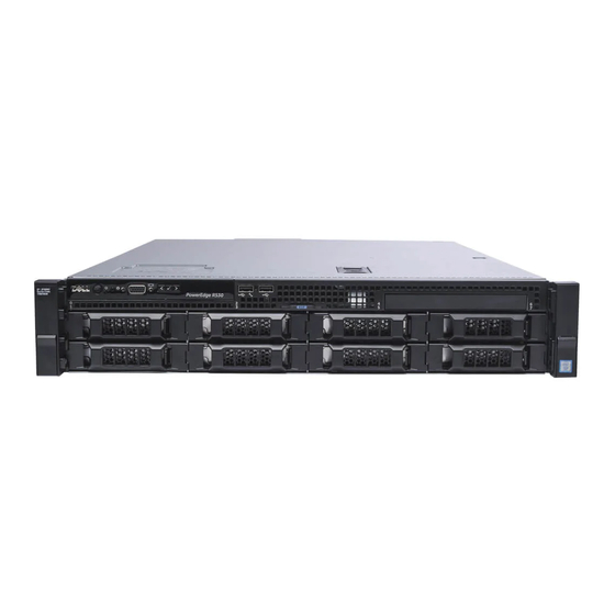
Dell PowerEdge R530 system overview The Dell PowerEdge R530 is a rack server that supports up to: • Two processors based on the Intel Xeon E5-2600 v3 or E5-2600 v4 product family • 12 DIMMs • Eight drive bays for hard drives or SSDs The PowerEdge R530 system is available in the following configurations: •... - Page 9 Figure 1. Supported configurations for the PowerEdge R530 system Dell PowerEdge R530 system overview...
-
Page 10: Front Panel Features
Press the system ID button: System identification button • To locate a particular system within a rack. • To turn the system ID on or off. Dell PowerEdge R530 system overview... -
Page 11: Lcd Panel
The LCD panel of your system provides system information, status, and error messages to indicate if the system is functioning correctly or if the system needs attention. For more information about error messages, see the Dell Event and Error Messages Reference Guide at Dell.com/openmanagemanuals >OpenManage software. -
Page 12: Setup Menu
DNS entries are available. Set error Select SEL to view LCD error messages in a format that matches the IPMI description in the SEL. This enables you to match an LCD message with an SEL entry. Dell PowerEdge R530 system overview... -
Page 13: Back Panel Features
Option Description Select Simple to view LCD error messages in a simplified user-friendly description. For more information about error messages, see the Dell Event and Error Messages Reference Guide at Dell.com/openmanagemanuals > OpenManage software. Set home Select the default information to be displayed on the Home screen. See View menu section for the options and option items that can be set as the default on the Home screen. -
Page 14: Back Panel Features For A Non-Redundant Power Supply Unit Chassis And A Redundant Power Supply Unit Chassis
Four integrated connectors that include: • Two 10/100/1000 Mbps NIC connectors • Two 100 Mbps/1 Gbps/10 Gbps SFP+/10 GbE T connectors Enables you to insert a vFlash media card. vFlash media card slot (optional) Dell PowerEdge R530 system overview... - Page 15 Icon Description Use the iDRAC8 Enterprise port to remotely access iDRAC. For iDRAC8 Enterprise port more information, see the Integrated Dell Remote Access Controller (optional) User’s Guide at Dell.com/idracmanuals. Full-height PCIe expansion card Enables you to connect up to two full-height PCI Express expansion slots (2) cards.
-
Page 16: Diagnostic Indicators
Check the System Event Log or system messages for the specific issue. For more information about error • When the system is turned on. messages, see the Dell Event and Error Messages • When the system is in standby. Reference Guide at Dell.com/openmanagemanuals >... -
Page 17: Hard Drive Indicator Codes
Flashes amber four times per second Drive failed Flashes green slowly Drive rebuilding Steady green Drive online Flashes green for three seconds, amber for three seconds, and Rebuild stopped then turns off after six seconds Dell PowerEdge R530 system overview... -
Page 18: Nic Indicator Codes
AC power supply units (PSUs) have an illuminated translucent handle that serves as an indicator and DC PSUs have an LED that serves as an indicator. The indicator shows whether power is present or a power fault has occurred. Dell PowerEdge R530 system overview... - Page 19 For AC PSUs, use only PSUs with the Extended Power Performance (EPP) label on the back. NOTE: Mixing PSUs from previous generations of Dell PowerEdge servers can result in a PSU mismatch condition or failure to turn the system on. Flashing amber Indicates a problem with the PSU.
- Page 20 AC PSU support both 220 V and 110 V input voltages with the exception of Titanium PSU, which support only 220 V. When two identical PSU receive different input voltages, they can output different wattages, and trigger a mismatch. Dell PowerEdge R530 system overview...
-
Page 21: Idrac Direct Led Indicator Codes
Not lit Indicates that the USB is ready to be removed or that a task is complete. The following table describes iDRAC Direct activity when configuring iDRAC Direct by using your laptop and cable (Laptop Connect): Dell PowerEdge R530 system overview... -
Page 22: Internal Dual Sd Module Indicator Codes
LED status indicator (2) The following table describes the IDSDM indicator codes: Table 11. IDSDM indicator codes Convention IDSDM indicator code Description Green Indicates that the card is online. Flashing green Indicates rebuild or activity. Dell PowerEdge R530 system overview... -
Page 23: Locating Service Tag Of Your System
Alternatively, the information may be on a sticker on the chassis of the system. This information is used by Dell to route support calls to the appropriate personnel. -
Page 24: Documentation Resources
For information about updating drivers and Dell.com/support/drivers firmware, see theMethods to download firmware and drivers section in this document. Managing your system For information about the features of the Dell Dell.com/openmanagemanuals OpenManage Systems Management, see the Dell OpenManage Systems Management Overview Guide. - Page 25 For information about installing and using Active Dell.com/asmdocs System Manager (ASM), see the Active System Manager User’s Guide. For understanding the features of Dell Lifecycle Dell.com/idracmanuals Controller (LCC), see the Dell Lifecycle Controller User’s Guide. For information about partner programs enterprise Dell.com/...
-
Page 26: Technical Specifications
The technical and environmental specifications of your system are outlined in this section. Chassis dimensions This section describes the physical dimensions of the system. Figure 11. Chassis dimensions of the PowerEdge R530 system Table 13. Dimensions of the Dell PowerEdge R530 system Za with bezel Za without bezel 668.715 mm... -
Page 27: Chassis Weight
The PowerEdge R530 system supports CR 2032 3.0-V lithium coin cell system battery. Expansion bus specifications The PowerEdge R530 system supports PCI Express Generation 2 and PCI Express Generation 3 expansion slots with an optional riser card. The following table provides the expansion card riser specifications: Table 16. -
Page 28: Memory Specifications
-length Slot 5 low-profile half -length Memory specifications The PowerEdge R530 system supports DDR4 registered DIMMs (RDIMMs). Supported memory bus frequencies are 1866 MT/s, 2133MT/s, or 2400 MT/s. Table 17. Memory specifications Memory module sockets Memory capacity Minimum RAM Maximum RAM Twelve 288–pin... -
Page 29: Nic Ports
9-pin connector, Data Terminal Equipment (DTE), 16550-compliant. VGA ports The Video Graphic Array (VGA) port enables you to connect the system to a VGA display. The PowerEdge R530 system supports two 15- pin VGA ports on the front and back panels. -
Page 30: Environmental Specifications
Environmental specifications NOTE: For additional information about environmental measurements for specific system configurations, see Dell.com/ environmental_datasheets. Table 20. Temperature specifications Temperature Specifications Storage –40°C to 65°C (–40°F to 149°F) Continuous operation (for altitude less than 950 m or 3117 10°C to 35°C (50°F to 95°F) with no direct sunlight on the equipment. -
Page 31: Particulate And Gaseous Contamination Specifications
Table 25. Operating temperature de-rating specifications Operating temperature de-rating Specifications Up to 35°C (95°F) Maximum temperature is reduced by 1°C/300 m (1°F/547 ft) above 950 m (3,117 ft). 35°C to 40°C (95°F to 104°F) Maximum temperature is reduced by 1°C/175 m (1°F/319 ft) above 950 m (3,117 ft). -
Page 32: Standard Operating Temperature
Tape Backup Unit (TBU) is not supported in Fresh Air. • Redundant power supplies are required. • Non Dell qualified peripheral cards and/or peripheral cards greater than 25 W are not supported. • PCIe SSD is not supported. Technical specifications... -
Page 33: Initial System Setup And Configuration
The Integrated Dell Remote Access Controller (iDRAC) is designed to make system administrators more productive and improve the overall availability of Dell systems. iDRAC alerts administrators to system issues, helps them perform remote system management, and reduces the need for physical access to the system. -
Page 34: Options To Install The Operating System
The default user name and password are root and calvin. You can also log in by using Single Sign-On or Smart Card. NOTE: You must have iDRAC credentials to log in to iDRAC. For more information about logging in to iDRAC and iDRAC licenses, see the Integrated Dell Remote Access Controller User's Guide at Dell.com/idracmanuals. Options to install the operating system If the system is shipped without an operating system, install the supported operating system by using one of the following resources: Table 30. - Page 35 Downloading the drivers and firmware Dell recommends that you download and install the latest BIOS, drivers, and systems management firmware on your system. Prerequisite Ensure that you clear the web browser cache before downloading the drivers and firmware. Steps Go to Dell.com/support/drivers.
-
Page 36: Pre-Operating System Management Applications
Options to manage the pre-operating system applications Your system has the following options to manage the pre-operating system applications: • System Setup • Boot Manager • Dell Lifecycle Controller • Preboot Execution Environment (PXE) Related link System Setup Boot Manager Dell Lifecycle Controller PXE boot System Setup By using the System Setup screen, you can configure the BIOS settings, iDRAC settings, and device settings of your system. -
Page 37: System Setup Details
The iDRAC settings utility is an interface to set up and configure the iDRAC parameters by using UEFI (Unified Extensible Firmware Interface). You can enable or disable various iDRAC parameters by using the iDRAC settings utility. For more information about this utility, see Integrated Dell Remote Access Controller User’s Guide at Dell.com/idracmanuals. -
Page 38: Boot Settings
Viewing System BIOS To view the System BIOS screen, perform the following steps: Turn on, or restart your system. Press F2 immediately after you see the following message: F2 = System Setup NOTE: If your operating system begins to load before you press F2, wait for the system to finish booting, and then restart your system and try again. - Page 39 Related link Boot Settings details System BIOS Viewing Boot Settings Choosing the system boot mode Changing the boot order Viewing Boot Settings To view the Boot Settings screen, perform the following steps: Turn on, or restart your system. Press F2 immediately after you see the following message: F2 = System Setup NOTE: If your operating system begins to load before you press F2, wait for the system to finish booting, and then...
-
Page 40: Choosing The System Boot Mode
Operating systems must be UEFI-compatible to be installed from the UEFI boot mode. DOS and 32-bit operating systems do not support UEFI and can only be installed from the BIOS boot mode. NOTE: For the latest information about supported operating systems, go to Dell.com/ossupport. Related link Boot Settings... -
Page 41: Network Settings Screen Details
Viewing Network Settings To view the Network Settings screen, perform the following steps: Turn on, or restart your system. Press F2 immediately after you see the following message: F2 = System Setup NOTE: If your operating system begins to load before you press F2, wait for the system to finish booting, and then restart your system and try again. -
Page 42: System Security
UEFI iSCSI Settings details The UEFI ISCSI Settings screen details are explained as follows: Option Description ISCSI Initiator Name Specifies the name of the iSCSI initiator (iqn format). ISCSI Device n (n = Enables or disables the iSCSI device. When disabled, a UEFI boot option is created for the iSCSI device 1 to 4) automatically. - Page 43 Option Description TPM Security NOTE: The TPM menu is available only when the TPM module is installed. Enables you to control the reporting mode of the TPM. The TPM Security option is set to Off by default. You can only modify the TPM Status, TPM Activation, and Intel TXT fields if the TPM Status field is set to either On with Pre-boot Measurements or On without Pre-boot Measurements.
-
Page 44: Using Your System Password To Secure Your System
Use the following guidelines to assign the system password: • A password can have up to 32 characters. • The password can contain the numbers 0 through 9. • Only the following special characters are allowed: space, (”), (+), (,), (-), (.), (/), (;), ([), (\), (]), (`). A message prompts you to reenter the system password. -
Page 45: Operating With A Setup Password Enabled
Operating with a setup password enabled If Setup Password is set to Enabled, type the correct setup password before modifying the system setup options. If you do not type the correct password in three attempts, the system displays the following message: Invalid Password! Number of unsuccessful password attempts: <x>... - Page 46 Option Description System Specifies the current version of the Management Engine firmware. Management Engine Version System Service Tag Specifies the system Service Tag. System Specifies the name of the system manufacturer. Manufacturer System Specifies the contact information of the system manufacturer. Manufacturer Contact Information...
-
Page 47: Processor Settings
Specifies the memory operating mode. The options available are Optimizer Mode, Advanced ECC Mode, Mirror Mode Mode, Spare Mode, Spare with Advanced ECC Mode, Dell Fault Resilient Mode and Dell NUMA Fault Resilient Mode. This option is set to Optimizer Mode by default. - Page 48 On the System BIOS screen, click Processor Settings. Related link Processor Settings Processor Settings details Processor Settings details The Processor Settings screen details are explained as follows: Option Description Logical Processor Enables or disables the logical processors and displays the number of logical processors. If this option is set to Enabled, the BIOS displays all the logical processors.
- Page 49 Option Description NOTE: The processor bus speed option displays only when both processors are installed. Processor 1 NOTE: Depending on the number of CPUs, there may be up to four processors listed. The following settings are displayed for each processor installed in the system: Option Description Family-Model-...
- Page 50 Option Description Embedded SATA Enables the embedded SATA option to be set to Off, ATA, AHCI, or RAID modes. This option is set to AHCI by default. Security Freeze Sends Security Freeze Lock command to the Embedded SATA drives during POST. This option is applicable only Lock for ATA and AHCI modes.
- Page 51 Option Description Port E Sets the drive type of the selected device. For Embedded SATA settings in ATA mode, set this field to Auto to enable BIOS support. Set it to OFF to turn off BIOS support. For AHCI or RAID mode, BIOS support is always enabled. Option Description Model...
- Page 52 Option Description Option Description Drive Type Specifies the type of drive attached to the SATA port. Capacity Specifies the total capacity of the hard drive. This field is undefined for removable media devices such as optical drives. Port J Sets the drive type of the selected device. For Embedded SATA settings in ATA mode, set this field to Auto to enable BIOS support.
- Page 53 Option Description USB 3.0 Setting Enables or disables the USB 3.0 support. Enable this option only if your operating system supports USB 3.0. If you disable this option, devices operate at USB 2.0 speed. USB 3.0 is enabled by default. User Accessible Enables or disables the USB ports.
- Page 54 Serial Communication You can use the Serial Communication screen to view the properties of the serial communication port. Related link Serial Communication details System BIOS Viewing Serial Communication Viewing Serial Communication To view the Serial Communication screen, perform the following steps: Turn on, or restart your system.
- Page 55 You can only change the rest of the options if the mode is set to Custom. This option is set to Performance Per Watt Optimized (DAPC) by default. DAPC is Dell Active Power Controller.
-
Page 56: Miscellaneous Settings
Option Description Turbo Boost Enables or disables the processor to operate in the turbo boost mode. This option is set to Enabled by default. Energy Efficient Enables or disables the Energy Efficient Turbo option. Turbo Energy Efficient Turbo (EET) is a mode of operation where a processor’s core frequency is adjusted to be within the turbo range based on workload. -
Page 57: Idrac Settings Utility
NOTE: Accessing some of the features on the iDRAC settings utility needs the iDRAC Enterprise License upgrade. For more information about using iDRAC, see Dell Integrated Dell Remote Access Controller User's Guide at Dell.com/idracmanuals. Related link Device Settings... -
Page 58: Device Settings
Dell Lifecycle Controller Dell Lifecycle Controller (LC) provides advanced embedded systems management capabilities including system deployment, configuration, update, maintenance, and diagnosis. LC is delivered as part of the iDRAC out-of-band solution and Dell system embedded Unified Extensible Firmware Interface (UEFI) applications. -
Page 59: Boot Manager
Launch System Enables you to access System Setup. Setup Launch Lifecycle Exits the Boot Manager and invokes the Dell Lifecycle Controller program. Controller System Utilities Enables you to launch System Utilities menu such as System Diagnostics and UEFI shell. Related link... -
Page 60: Pxe Boot
System Utilities System Utilities contains the following utilities that can be launched: • Launch Diagnostics • BIOS Update File Explorer • Reboot System Related link Boot Manager PXE boot The Preboot Execution Environment (PXE) is an industry standard client or interface that allows networked computers that are not yet loaded with an operating system to be configured and booted remotely by an administrator. -
Page 61: Installing And Removing System Components
Installing and removing system components This section provides information about installing and removing the system components. Topics: • Safety instructions • Before working inside your system • After working inside your system • Recommended tools • Front bezel (optional) • System cover •... -
Page 62: Before Working Inside Your System
Damage due to servicing that is not authorized by Dell is not covered by your warranty. Read and follow the safety instructions that are shipped with your product. -
Page 63: Front Bezel (Optional)
You need the following tools to assemble the cables for a DC power supply unit. • AMP 90871-1 hand-crimping tool or equivalent • Wire-stripper pliers to remove insulation from size 10 AWG solid or stranded, insulated copper wire NOTE: Use alpha wire part number 3080 or equivalent (65/30 stranding). Front bezel (optional) The front bezel is attached to the front side of the server and prevents accidents while removing the hard drive or when pressing the reset or power button. -
Page 64: Installing The Optional Front Bezel
Installing the optional front bezel Prerequisite Follow the safety guidelines listed in the Safety instructions section. Steps Locate and remove the bezel key. NOTE: The bezel key is attached to the back of the bezel. Hook the right end of the bezel onto the chassis. Fit the free end of the bezel onto the system. -
Page 65: Installing The System Cover
Steps Rotate the latch release lock counter clockwise to the unlocked position. Lift the latch toward the back of the system. The system cover slides back and the tabs on the system cover disengage from the slots on the chassis. NOTE: The position of the latch may vary depending on the configuration of your system. -
Page 66: Inside The System
Damage due to servicing that is not authorized by Dell is not covered by your warranty. Read and follow the safety instructions that are shipped with your product. - Page 67 Figure 16. Inside the system—Redundant power supply unit chassis Control panel board Hard drive backplane Cooling fan (5) Power interposer board Power supply unit (redundant) Optional expansion card riser Processor (2) DIMM (12) Installing and removing system components...
-
Page 68: Cooling Shroud
Damage due to servicing that is not authorized by Dell is not covered by your warranty. Read and follow the safety instructions that are shipped with your product. - Page 69 Follow the procedure listed in the Before working inside your system section. If connected, disconnect the cables from expansion card (s). NOTE: If required, close the expansion card latch on the cooling shroud to release the full length card. If installed, remove the expansion card riser. CAUTION: Never operate your system with the cooling shroud removed.
-
Page 70: Installing The Cooling Shroud
Damage due to servicing that is not authorized by Dell is not covered by your warranty. Read and follow the safety instructions that are shipped with your product. -
Page 71: System Memory
Related link Safety instructions Before working inside your system After working inside your system Installing an expansion card into the expansion card riser Installing the optional expansion card riser System memory Your system supports DDR4 registered DIMMs (RDIMMs). It supports DDR4 voltage specifications. NOTE: MT/s indicates DIMM speed in MegaTransfers per second. -
Page 72: General Memory Module Installation Guidelines
Table 32. Memory channels Processor Channel 0 Channel 1 Channel 2 Channel 3 Processor 1 slots A1 and A5 slots A2 and A6 slots A3 and A7 slots A4 and A8 Processor 2 slot B1 slot B2 slot B3 slot B4 The following table shows the memory populations and operating frequencies for the supported configurations. -
Page 73: Sample Memory Configurations
Sample memory configurations The following tables show sample memory configurations for one and two processor configurations that follow the appropriate memory guidelines. NOTE: 1R and 2R in the following tables indicate single- and dual-rank DIMMs respectively. Table 34. Memory configurations—single processor System Capacity DIMM Size (in Number of... - Page 74 System Capacity DIMM Size (in Number of DIMM Rank, Organization, DIMM Slot Population (in GB) DIMMs and Frequency 1R, x8, 2400 MT/s, A1, A2, A3, A4, A5, A6, A7, A8 1R, x8, 2133 MT/s, 1R, x8, 1866 MT/s 1R, x8, 2400 MT/s, A1, A2, A3, A4 1R, x8, 2133 MT/s, 1R, x8, 1866 MT/s...
- Page 75 System Capacity DIMM Size (in Number of DIMM Rank, Organization, DIMM Slot Population (in GB) DIMMs and Frequency 2R, x8, 2400 MT/s, A1, A2, A3 2R, x4, 2133 MT/s, 2R, x4, 1866 MT/s 2R, x8, 2400 MT/s, A1, A2, A3, A4, A5, A6, A7, A8 2R, x4, 2133 MT/s, 2R, x4, 1866 MT/s, 2R, x8, 2400 MT/s,...
- Page 76 System DIMM Size (in GB) Number of DIMMs DIMM Rank, Organization, DIMM Slot Population Capacity (in and Frequency 1R, x8, 1866 MT/s 1R, x8, 2400 MT/s, A1, A2, A3, A4, B1, B2, B3, B4 1R, x8, 2133 MT/s, 1R, x8, 1866 MT/s 2R, x8, 2400 MT/s, A1, A2, B1, B2 2R, x8, 2133 MT/s,...
- Page 77 System DIMM Size (in GB) Number of DIMMs DIMM Rank, Organization, DIMM Slot Population Capacity (in and Frequency 2R, x8, 2133 MT/s, 2R, x8, 1866 MT/s 2R, x4, 2400 MT/s, A1, A2, A3, A4, B1, B2, B3, B4 2R, x4, 2133 MT/s, 2R, x4, 1866 MT/s 2R, x4, 2400 MT/s, A1, A2, B1, B2...
-
Page 78: Removing Memory Modules
Damage due to servicing that is not authorized by Dell is not covered by your warranty. Read and follow the safety instructions that are shipped with your product. -
Page 79: Installing Memory Modules
Damage due to servicing that is not authorized by Dell is not covered by your warranty. Read and follow the safety instructions that are shipped with your product. -
Page 80: Hard Drives
Press the memory module with your thumbs until the socket levers firmly click into place. When the memory module is properly seated in the socket, the levers on the memory module socket align with the levers on the other sockets that have memory modules installed. Figure 22. -
Page 81: Removing A Hot Swappable Hard Drive Or Ssd
Damage due to servicing that is not authorized by Dell is not covered by your warranty. Read and follow the safety instructions that came with the product. -
Page 82: Installing A Hot-Swap Hard Drive
Damage due to servicing that is not authorized by Dell is not covered by your warranty. Read and follow the safety instructions that are shipped with your product. -
Page 83: Removing A 3.5-Inch Hard Drive Blank
Damage due to servicing that is not authorized by Dell is not covered by your warranty. Read and follow the safety instructions that came with the product. -
Page 84: Installing A 3.5-Inch Hard Drive Blank
Figure 25. Removing a 3.5-inch hard drive blank hard drive blank release button Next step If applicable, install the front bezel. Related link Safety instructions Removing the optional front bezel Installing the optional front bezel Installing a 3.5-inch hard drive blank Prerequisites Follow the safety guidelines listed in the Safety instructions section. -
Page 85: Removing A 2.5-Inch Hot Swappable Hard Drive From A 3.5-Inch Hard Drive Adapter
Damage due to servicing that is not authorized by Dell is not covered by your warranty. Read and follow the safety instructions that came with the product. -
Page 86: Installing A 2.5-Inch Hot Swappable Hard Drive Into A 3.5-Inch Hard Drive Adapter
Damage due to servicing that is not authorized by Dell is not covered by your warranty. Read and follow the safety instructions that are shipped with your product. -
Page 87: Removing A 3.5-Inch Hot Swappable Hard Drive Adapter From A 3.5-Inch Hot Swappable Hard Drive Carrier
Damage due to servicing that is not authorized by Dell is not covered by your warranty. Read and follow the safety instructions that are shipped with your product. -
Page 88: Removing A Hard Drive From A Hard Drive Carrier
Keep the Phillips #2 screwdriver ready. Install the 2.5-inch hot swappable hard drive into the 3.5-inch hard drive adapter. Steps Insert the 3.5-inch hard drive adapter into the 3.5-inch hot swappable hard drive carrier with the connector end of the hard drive toward the back of the 3.5-inch hot swappable hard drive carrier. -
Page 89: Installing A Hard Drive Into A Hard Drive Carrier
Damage due to servicing that is not authorized by Dell is not covered by your warranty. Read and follow the safety instructions that are shipped with your product. -
Page 90: Optical Drive (Optional)
Damage due to servicing that is not authorized by Dell is not covered by your warranty. Read and follow the safety instructions that are shipped with your product. -
Page 91: Installing The Optional Optical Drive
Damage due to servicing that is not authorized by Dell is not covered by your warranty. Read and follow the safety instructions that are shipped with your product. -
Page 92: Cooling Fans
Damage due to servicing that is not authorized by Dell is not covered by your warranty. Read and follow the safety instructions that are shipped with your product. -
Page 93: Installing A Cooling Fan
Damage due to servicing that is not authorized by Dell is not covered by your warranty. Read and follow the safety instructions that are shipped with your product. -
Page 94: Internal Usb Memory Key (Optional)
Follow the procedure listed in the Before working inside your system section. Steps Align the fan with the cable end of the fan toward the system board connector . Lower the fan into the fan bracket until it clicks into position. Connect the fan power cable to the corresponding power connector on the system board . -
Page 95: Replacing The Optional Internal Usb Memory Key
Damage due to servicing that is not authorized by Dell is not covered by your warranty. Read and follow the safety instructions that are shipped with your product. -
Page 96: Expansion Cards And Expansion Card Riser
Figure 38. Installing the internal USB memory key USB memory key USB port Next steps Follow the procedure listed in the After working inside your system section. While booting, press F2 to enter System Setup and verify that the system detects the USB memory key. Related link Safety instructions System board connectors... - Page 97 Table 37. Expansion card slots available on system board only Location PCIe slot Processor connection Height Length Link width Slot width System board Processor 2 Low profile Half length System board Processor 1 Low profile Half length System board Processor 1 Low profile Half length System board...
-
Page 98: Removing An Expansion Card From The System Board
Damage due to servicing that is not authorized by Dell is not covered by your warranty. Read and follow the safety instructions that are shipped with your product. -
Page 99: Installing An Expansion Card On The System Board
Damage due to servicing that is not authorized by Dell is not covered by your warranty. Read and follow the safety instructions that are shipped with your product. -
Page 100: Removing The Optional Expansion Card Riser
Damage due to servicing that is not authorized by Dell is not covered by your warranty. Read and follow the safety instructions that are shipped with your product. -
Page 101: Installing The Optional Expansion Card Riser
Follow the procedure listed in the Before working inside your system section. Remove the cooling shroud. Step Holding the touch points, lift the expansion card riser from the riser connector on the system board. Figure 41. Removing the expansion card riser expansion card riser cage riser guide on riser cage riser guide on chassis... -
Page 102: Removing An Expansion Card From The Expansion Card Riser
Damage due to servicing that is not authorized by Dell is not covered by your warranty. Read and follow the safety instructions that are shipped with your product. - Page 103 NOTE: If applicable, close the expansion card latch on the cooling shroud to release the full length card. Steps Press the expansion card retention latch down and turn the latch counterclockwise to open. Pull the expansion card away from the riser. If you want to remove the expansion card permanently, install a metal filler bracket over the empty expansion slot opening and close the expansion card latch.
-
Page 104: Installing An Expansion Card Into The Expansion Card Riser
Damage due to servicing that is not authorized by Dell is not covered by your warranty. Read and follow the safety instructions that are shipped with your product. - Page 105 Figure 45. Installing an expansion card from the expansion card riser expansion card riser expansion card riser cage expansion card retention latch expansion card Figure 46. Installing a full height, full length expansion card from the expansion card riser full height, full length expansion card latch (on cooling full height, full length expansion card shroud) expansion card riser cage...
-
Page 106: Idrac Port Card (Optional)
Damage due to servicing that is not authorized by Dell is not covered by your warranty. Read and follow the safety instructions that are shipped with your product. -
Page 107: Installing The Idrac Ports Card
Damage due to servicing that is not authorized by Dell is not covered by your warranty. Read and follow the safety instructions that are shipped with your product. - Page 108 Follow the safety guidelines listed in the Safety instructions section. Follow the procedure listed in the Before working inside your system section. Remove the cooling shroud. NOTE: If applicable, close the expansion card latch on the cooling shroud to release the full length card. If applicable, disconnect the cables from expansion card (s).
-
Page 109: Sd Vflash Card (Optional)
It emulates USB device(s). For more information, see the Integrated Dell Remote Access Controller User's Guide at Dell.com/idracmanuals. Removing the optional SD vFlash card Prerequisites Follow the safety guidelines listed in the Safety instructions section. -
Page 110: Removing An Internal Sd Card
Damage due to servicing that is not authorized by Dell is not covered by your warranty. Read and follow the safety instructions that are shipped with your product. -
Page 111: Installing An Internal Sd Card
Damage due to servicing that is not authorized by Dell is not covered by your warranty. Read and follow the safety instructions that are shipped with your product. - Page 112 Figure 51. Installing an internal SD card IDSDM SD card 2 SD card 1 SD card slot 1 SD card slot 2 Next step Related link Safety instructions Before working inside your system After working inside your system Removing the cooling shroud Removing the optional expansion card riser Installing the optional expansion card riser Installing the cooling shroud...
-
Page 113: Removing The Optional Internal Dual Sd Module
Damage due to servicing that is not authorized by Dell is not covered by your warranty. Read and follow the safety instructions that are shipped with your product. -
Page 114: Installing The Optional Internal Dual Sd Module
Damage due to servicing that is not authorized by Dell is not covered by your warranty. Read and follow the safety instructions that are shipped with your product. -
Page 115: Removing The Integrated Storage Controller Card
Damage due to servicing that is not authorized by Dell is not covered by your warranty. Read and follow the safety instructions that are shipped with your product. - Page 116 Figure 54. Removing the integrated storage controller card integrated storage controller cable integrated storage controller card integrated storage controller card connector on the integrated storage controller card holder system board Next steps If applicable, install the PCIe expansion-card riser. If applicable, connect the required power or data cables to the expansion card(s). Reinstall the cooling shroud.
-
Page 117: Installing The Integrated Storage Controller Card
Damage due to servicing that is not authorized by Dell is not covered by your warranty. Read and follow the safety instructions that are shipped with your product. -
Page 118: Processors And Heat Sinks
Figure 55. Installing the integrated storage controller card integrated storage controller cable integrated storage controller card integrated storage controller card connector on the integrated storage controller card holder system board Next steps If applicable, install the PCIe expansion-card riser. If applicable, connect the required power or data cables to the expansion card(s). Reinstall the cooling shroud. -
Page 119: Removing A Heat Sink
Damage due to servicing that is not authorized by Dell is not covered by your warranty. Read and follow the safety instructions that came with the product. -
Page 120: Removing A Processor
Damage due to servicing that is not authorized by Dell is not covered by your warranty. Read and follow the safety instructions that are shipped with your product. - Page 121 NOTE: You can update the system BIOS by using the Dell Lifecycle Controller. NOTE: To ensure proper system cooling, you must install a processor blank in any empty processor socket. Follow the safety guidelines listed in the Safety instructions section.
- Page 122 Figure 57. Processor shield close first socket release lever lock icon processor open first socket release lever unlock icon Installing and removing system components...
- Page 123 Figure 58. Removing a processor close first socket-release lever pin-1 indicator of processor processor slot (4) processor shield open first socket-release lever socket socket keys (4) Next steps Replace the processor(s). Install the heat sink. If removed, reinstall the PCIe expansion card riser. If disconnected, reconnect the cables to the expansion card(s).
-
Page 124: Installing A Processor
Damage due to servicing that is not authorized by Dell is not covered by your warranty. Read and follow the safety instructions that are shipped with your product. - Page 125 Figure 59. Installing a processor socket-release lever 1 pin–1 corner of the processor processor slot (4) processor shield socket-release lever 2 processor socket tab (4) Next steps NOTE: Ensure that you install the heat sink after you install the processor. The heat sink is necessary to maintain proper thermal conditions.
-
Page 126: Installing A Heat Sink
Damage due to servicing that is not authorized by Dell is not covered by your warranty. Read and follow the safety instructions that are shipped with your product. -
Page 127: Power Supply Units (Psu)
thermal grease syringe Place the heat sink onto the processor. Tighten one of the four screws to secure the heat sink to the system board. Tighten the screw diagonally opposite to the first screw you have tightened. NOTE: Do not over-tighten the heat sink retention screws when installing the heat sink. To prevent over-tightening, tighten the retention screw until resistance is felt, and stop after the screw is seated. -
Page 128: Hot Spare Feature
Damage due to servicing that is not authorized by Dell is not covered by your warranty. Read and follow the safety instructions that are shipped with your product. -
Page 129: Installing The Power Supply Unit Blank
Damage due to servicing that is not authorized by Dell is not covered by your warranty. Read and follow the safety instructions that are shipped with your product. -
Page 130: Removing An Ac Power Supply Unit
Damage due to servicing that is not authorized by Dell is not covered by your warranty. Read and follow the safety instructions that are shipped with your product. -
Page 131: Installing An Ac Power Supply Unit
Damage due to servicing that is not authorized by Dell is not covered by your warranty. Read and follow the safety instructions that are shipped with your product. -
Page 132: Non-Redundant Ac Power Supply Unit (Cabled)
Damage due to servicing that is not authorized by Dell is not covered by your warranty. Read and follow the safety instructions that are shipped with your product. - Page 133 NOTE: If applicable, close the expansion card latch on the cooling shroud to release the full length card. If applicable, disconnect the power or data cables from expansion card (s). If applicable, remove the expansion-card riser Steps Disconnect the power cable from the power source. Disconnect the power cable from the power supply unit (PSU) and remove the power cables from the cable strap.
- Page 134 Damage due to servicing that is not authorized by Dell is not covered by your warranty. Read and follow the safety instructions that are shipped with your product.
- Page 135 Figure 67. Installing a non redundant AC PSU standoff on the chassis screw non-redundant PSU PSU unit cage P1 cable connector P2 cable connector P3 cable connector backplane connector Next steps If applicable, install the PCIe expansion card riser. If applicable, connect the required power or data cables to the expansion card(s). Reinstall the cooling shroud.
-
Page 136: Wiring Instructions For A Dc Power Supply Unit
DC power and to safety grounds. Do not attempt connecting to DC power or installing grounds yourself. All electrical wiring must comply with applicable local or national codes and practices. Damage due to servicing that is not authorized by Dell is not covered by your warranty. - Page 137 DC power and to safety grounds. Do not attempt connecting to DC power or installing grounds yourself. All electrical wiring must comply with applicable local or national codes and practices. Damage due to servicing that is not authorized by Dell is not covered by your warranty.
- Page 138 DC power and to safety grounds. Do not attempt connecting to DC power or installing grounds yourself. All electrical wiring must comply with applicable local or national codes and practices. Damage due to servicing that is not authorized by Dell is not covered by your warranty.
-
Page 139: Removing A Dc Power Supply Unit
DC power and to safety grounds. Do not attempt connecting to DC power or installing grounds yourself. All electrical wiring must comply with applicable local or national codes and practices. Damage due to servicing that is not authorized by Dell is not covered by your warranty. -
Page 140: Installing A Dc Power Supply Unit
DC power and to safety grounds. Do not attempt connecting to DC power or installing grounds yourself. All electrical wiring must comply with applicable local or national codes and practices. Damage due to servicing that is not authorized by Dell is not covered by your warranty. -
Page 141: Power Interposer Board
Damage due to servicing that is not authorized by Dell is not covered by your warranty. Read and follow the safety instructions that are shipped with your product. - Page 142 If applicable, remove the expansion card riser CAUTION: To prevent damage to the power interposer board, you must remove the power supply module(s) or power supply blank from the system before removing the power interposer board or power distribution board. Steps Remove the power supply module(s) from the back of the chassis.
-
Page 143: Installing The Power Interposer Board
Damage due to servicing that is not authorized by Dell is not covered by your warranty. Read and follow the safety instructions that are shipped with your product. - Page 144 Damage due to servicing that is not authorized by Dell is not covered by your warranty. Read and follow the safety instructions that are shipped with your product.
-
Page 145: Hard Drive Backplane
Damage due to servicing that is not authorized by Dell is not covered by your warranty. Read and follow the safety instructions that are shipped with your product. - Page 146 SAS B connector hard drive connectors (8) Figure 78. Cabling diagram of the hard drive backplane using the onboard controller system board SATA A cable connector on system board SATA B cable connector on system board signal cable connector on system board hard drive backplane SAS B cable connector on backplane signal cable connector on backplane...
-
Page 147: Installing The Hard Drive Backplane
Figure 79. Cabling diagram of the hard drive backplane using the integrated storage controller system board integrated storage controller connector integrated storage controller signal cable connector on system board hard drive backplane SAS B cable connector on backplane signal cable connector on backplane SAS A cable connector on backplane Next steps Reconnect the data cable(s) and power cable to the hard drive backplane... - Page 148 Damage due to servicing that is not authorized by Dell is not covered by your warranty. Read and follow the safety instructions that are shipped with your product.
-
Page 149: Control Panel
Damage due to servicing that is not authorized by Dell is not covered by your warranty. Read and follow the safety instructions that are shipped with your product. -
Page 150: Installing The Control Panel Board
Damage due to servicing that is not authorized by Dell is not covered by your warranty. Read and follow the safety instructions that are shipped with your product. -
Page 151: Removing The Control Panel
Damage due to servicing that is not authorized by Dell is not covered by your warranty. Read and follow the safety instructions that are shipped with your product. - Page 152 Steps Disconnect the display module cable from the control panel board. NOTE: The control panel has seven tabs that secure it to the chassis. CAUTION: Applying excessive force may damage the control panel. Slide the display module cable out of the plastic cable guide. Remove the cable guide after unscrewing the two retaining screws.
-
Page 153: Installing The Control Panel
Damage due to servicing that is not authorized by Dell is not covered by your warranty. Read and follow the safety instructions that are shipped with your product. -
Page 154: System Board
Damage due to servicing that is not authorized by Dell is not covered by your warranty. Read and follow the safety instructions that are shipped with your product. - Page 155 Remove the screws securing the system board to the chassis. Figure 85. Screw location on the system board system board screw (9) system board holder Hold the system board holder, lift the system board and slide it toward the front of the chassis. Installing and removing system components...
-
Page 156: Installing The System Board
Damage due to servicing that is not authorized by Dell is not covered by your warranty. Read and follow the safety instructions that are shipped with your product. - Page 157 Follow the safety guidelines listed in the Safety instructions section. Follow the procedure listed in the Before working inside your system section. Keep the Phillips #2 screwdriver ready. Steps Unpack the new system board assembly. CAUTION: Do not lift the system board by holding a memory module, processor, or other components. CAUTION: Take care not to damage the system identification button while placing the system board into the chassis.
-
Page 158: Restoring The Service Tag By Using The Easy Restore Feature
If Easy Restore does not function, enter the system service tag manually and import your new or existing iDRAC Enterprise license. For more information, see Integrated Dell Remote Access Controller 8 (iDRAC8) User's Guide, at Dell.com/esmmanuals. Update the BIOS and iDRAC versions. -
Page 159: Entering The System Service Tag By Using System Setup
Damage due to servicing that is not authorized by Dell is not covered by your warranty. Read and follow the safety instructions that are shipped with your product. -
Page 160: Initializing The Tpm For Bitlocker Users
Figure 88. Installing the TPM rivet slot on the system board plastic rivet TPM connector Next steps Install the system board. Follow the procedure listed in the After working inside your system section. Related link Safety instructions Before working inside your system After working inside your system Initializing the TPM for BitLocker users Initialize the TPM. -
Page 161: Troubleshooting Your System
Damage due to servicing that is not authorized by Dell is not covered by your warranty. Read and follow the safety instructions that are shipped with your product. -
Page 162: Troubleshooting External Connections
Next step If the tests fail, see the Getting help section. Related link Getting help Contacting Dell Troubleshooting a USB device Prerequisite NOTE: Follow steps 1 to 6 to troubleshoot a USB keyboard or mouse. For other USB devices, go to step 7. -
Page 163: Troubleshooting Idrac Direct (Usb Xml Configuration)
Getting help Troubleshooting iDRAC Direct (USB XML configuration) For information about USB storage device and server configuration, see the Integrated Dell Remote Access Controller User's Guide at Dell.com/idracmanuals. Steps Ensure that your USB storage device is connected to the front USB Management Port, identified by icon. -
Page 164: Troubleshooting A Nic
Damage due to servicing that is not authorized by Dell is not covered by your warranty. Read and follow the safety instructions that are shipped with your product. -
Page 165: Troubleshooting A Damaged System
Damage due to servicing that is not authorized by Dell is not covered by your warranty. Read and follow the safety instructions that are shipped with your product. -
Page 166: Troubleshooting The System Battery
Damage due to servicing that is not authorized by Dell is not covered by your warranty. Read and follow the safety instructions that are shipped with your product. -
Page 167: Troubleshooting Cooling Problems
Damage due to servicing that is not authorized by Dell is not covered by your warranty. Read and follow the safety instructions that are shipped with your product. -
Page 168: Troubleshooting System Memory
Damage due to servicing that is not authorized by Dell is not covered by your warranty. Read and follow the safety instructions that are shipped with your product. -
Page 169: Troubleshooting An Internal Usb Key
Damage due to servicing that is not authorized by Dell is not covered by your warranty. Read and follow the safety instructions that are shipped with your product. -
Page 170: Troubleshooting An Optical Drive
Damage due to servicing that is not authorized by Dell is not covered by your warranty. Read and follow the safety instructions that are shipped with your product. -
Page 171: Troubleshooting A Hard Drive
Damage due to servicing that is not authorized by Dell is not covered by your warranty. Read and follow the safety instructions that are shipped with your product. -
Page 172: Troubleshooting Expansion Cards
Damage due to servicing that is not authorized by Dell is not covered by your warranty. Read and follow the safety instructions that are shipped with your product. -
Page 173: Troubleshooting Processors
Damage due to servicing that is not authorized by Dell is not covered by your warranty. Read and follow the safety instructions that are shipped with your product. -
Page 174: Alert Messages
Related link Getting help Using system diagnostics Alert messages The systems management software generates alert messages for your system. Alert messages include information, status, warning, and failure messages for drive, temperature, fan, and power conditions. For more information, see the systems management software documentation links listed in the Documentation resources section of this manual. -
Page 175: Using System Diagnostics
Using system diagnostics If you experience a problem with your system, run the system diagnostics before contacting Dell for technical assistance. The purpose of running system diagnostics is to test your system hardware without requiring additional equipment or risking data loss. If you are unable to fix the problem yourself, service and support personnel can use the diagnostics results to help you solve the problem. -
Page 176: System Diagnostic Controls
The ePSA Pre-boot System Assessment window is displayed, listing all devices detected in the system. The diagnostics starts executing the tests on all the detected devices. System diagnostic controls Menu Description Configuration Displays the configuration and status information of all detected devices. Results Displays the results of all tests that are run. -
Page 177: Jumpers And Connectors
Jumpers and connectors This topic provides specific information about the system jumpers. It also provides some basic information about jumpers and switches and describes the connectors on the various boards in the system. Jumpers on the system board help to disable system and setup passwords. You must know the connectors on the system board to install components and cables correctly. -
Page 178: System Board Connectors
System board connectors Figure 89. System board connectors and jumpers Table 42. System board connectors and jumpers Item Connector Description PCIE_G2_X1 and PCIE _G2_X4 PCIE Slot 5 (x4) and Slot 4 (x1) PCIE_G3_X16 and PCIE_G3_X16 PCIE Slot 3 (next to Slot 4) and Slot 2 (next to Slot 1) PCIE_G3_X8 PCIE card Slot 1 BATTERY... -
Page 179: Disabling A Forgotten Password
Damage due to servicing that is not authorized by Dell is not covered by your warranty. Read and follow the safety instructions that are shipped with your product. - Page 180 The existing passwords are not disabled (erased) until the system boots with the jumper on pins 2 and 4. However, before you assign a new system and/or setup password, you must move the jumper back to pins 4 and 6. NOTE: If you assign a new system and/or setup password with the jumper on pins 2 and 4, the system disables the new password(s) the next time it boots.
-
Page 181: Getting Help
Contacting Dell Dell provides several online and telephone-based support and service options. If you do not have an active internet connection, you can find contact information about your purchase invoice, packing slip, bill, or Dell product catalog. Availability varies by country and product, and some services may not be available in your area. -
Page 182: Quick Resource Locator (Qrl)
Steps Go to Dell.com/QRL and navigate to your specific product or Use your smartphone or tablet to scan the model-specific Quick Resource (QR) code on your Dell PowerEdge system or in the Quick Resource Locator section. Quick Resource Locator (QRL) Use the Quick Resource Locator (QRL) to get immediate access to system information and how-to videos.