Table of Contents
Advertisement
Quick Links
Download this manual
See also:
User Manual
Advertisement
Table of Contents
Troubleshooting

Related Manuals for Philips VL3015LT


Summary of Contents for Philips VL3015LT
- Page 2 10911 Petal Street Dallas, Texas 75238 USA This manual is for informational use only and is subject to change without notice. Philips Vari-Lite assumes no responsibility or liability for any claims resulting from errors or inaccuracies that may appear in this manual.
- Page 3 Note: *When returning products to Philips Vari-Lite for repairs (warranty or out-of-warranty) from a country other than the USA, “Philips Lighting Controls Division”, must appear in the address block as the Importer of Record (IOR) on all shipping documentation, Commercial Invoices, etc. This must be done in order to clear customs in a timely manner and prevent returns.
- Page 4 Declaration of Conformity We, Philips Lighting B.V. 10911 Petal Street, Dallas, Texas 75238 USA, declare under our responsibility for the products: Product Range...
-
Page 5: Safety Notice
WARNING: INSTRUCTIONS FOR CONTINUED PROTECTION AGAINST FIRE 1. VARI❋LITE luminaires have been designed for use with specific lamp types. VL3015LT Spot Luminaires is supplied with an Osram HTI 1500 D7/60 metal halide lamp or other lamps as approved by Vari-Lite. Installing another type of lamp not approved by Vari-Lite may be hazardous. - Page 6 ❋ VARI LITE - VL3015LT S UMINAIRE ERVICE ANUAL WARNING: INSTRUCTIONS FOR CONTINUED PROTECTION AGAINST EXCESSIVE EXPOSURE TO UV RADIATION 1. Many VARI❋LITE luminaires use a lamp that produces UV radiation. DO NOT look directly at lamp. 2. It is hazardous to operate luminaires without lens or shield. Shields, lenses, or ultraviolet screens shall be changed if they have become visibly damaged to such an extent that their effectiveness is impaired.
- Page 7 OREWORD Sicherheitshinweise Es ist äußerst wichtig, ALLE Sicherheitsinformationen und -hinweise in diesem Handbuch und dem beiliegenden Informationsmaterial zu lesen, bevor Sie die hierin beschriebenen Produkte installieren bzw. bedienen. Halten Sie bei der Installation und dem Einsatz dieses Produkts alle Warnhinweise und Vorsichtsmaßnahmen ein.
- Page 8 ❋ VARI LITE - VL3015LT S UMINAIRE ERVICE ANUAL WARNUNG: HINWEISE ZUM SCHUTZ GEGEN ÜBERHÖHTE UV-STRAHLUNG 1. Viele VARI❋LITE -Scheinwerfer verwenden die Lampentyp, der UV-Strahlen abgibt. SCHAUEN SIE NICHT direkt in die Lampe. 2. Es ist gefährlich, Leuchten ohne Linsen oder Blenden zu bedienen. Blenden, Linsen oder Ultraviolettschirme müssen ausgetauscht werden, sofern deren Schutzwirkung durch sichtbare...
- Page 9 OREWORD Notes de sécurité Avant de procéder à l’installation des produits décrits dans ce guide et de les mettre en marche, il est extrêmement important de lire TOUS les renseignements et TOUTES les directives de sécurité contenues dans ce guide ainsi que toute documentation jointe. Tenir compte de tous les avertissements et suivre toutes les précautions pendant l’installation et l’utilisation de cet appareil.
- Page 10 ❋ VARI LITE - VL3015LT S UMINAIRE ERVICE ANUAL AVERTISSEMENT: DIRECTIVES POUR SE PROTÉGER CONTRE UNE EXPOSITION EXCESSIVE AUX RAYONS UV 1. Plusieurs luminaires VARI❋LITE utilisent une lampe qui produit des rayons UV. NE PAS fixer son regard sur la lampe.
- Page 11 OREWORD Aviso sobre Seguridad Es muy importante leer TODA la información e instrucciones sobre seguridad que se indica en este manual así como en los documentos adjuntos antes de instalar y operar los productos descritos. Se debe prestar atención a todos los avisos y advertencias durante la instalación y uso de este producto. Los símbolos de seguridad usados en este manual son los siguientes: CUIDADO, indica posibles daños al producto.
- Page 12 ❋ VARI LITE - VL3015LT S UMINAIRE ERVICE ANUAL ADVERTENCIA: INSTRUCCIONES PARA PROTECCIÓN CONTINUA CONTRA LA EXPOSICIÓN EXCESIVA DE RADIACIÓN ULTRA VIOLETA 1. Muchas luminarias VARI❋LITE usan un tipo de lámpara que produce radiación UV. NO mire directamente a la lámpara.
- Page 13 OREWORD 02.96 98.001 0 0...
- Page 14 ❋ VARI LITE - VL3015LT S UMINAIRE ERVICE ANUAL 0 2.9698 .0 010 0...
-
Page 15: Table Of Contents
Enclosure Components ......................7 Principles of Operation Functional Block Diagram ......................8 Chapter 2. Maintenance Testing Luminaire Self-Tests ....................... 10 Calibration Sequence - VL3015LT Spot Luminaire ............... 10 Auto Recalibration ........................11 Partial Recalibration........................ 11 Sensor Testing ......................... 11 Troubleshooting Error Messages........................13 Troubleshooting Guide...................... - Page 16 Chapter 3. Illustrated Parts Breakdown Drawing Trees VL3015LT Spot Luminaire..................... 62 Top Assembly Included Items Kit, VL3015LT Spot ..................65 VL3015LT Spot Luminaire..................... 67 Generic Luminaire Assembly ....................70 Head Cover Assembly ......................73 Gobo Clamp (with Cover Support) Assembly................ 74 Gobo Clamp Assembly ......................
- Page 17 ABLE OF ONTENTS Strobe System Assembly ...................... 104 Top Strobe Blade Assembly....................106 Bottom Strobe Blade Assembly .................... 107 Fixed Color Wheel 2 Assembly .................... 108 Fixed Color Wheel 1 Assembly .................... 110 Yoke Assembly Yoke Assembly ........................113 Tilt Motor Assembly ......................115 Yoke Fan Assembly ......................
- Page 18 Optics Bulkhead Cable Assembly..................160 Ignitor to Lamp Socket Cable Assembly ................161 LVS Chassis Ground Cable Assembly.................. 162 Appendix A. Technical Notices & Bulletins VL3015LT Spot Luminaires ....................163 Technical Notices ......................163 Technical Bulletins......................163 0 2.9698 .0 010 0...
-
Page 19: Introduction
About This Manual This manual provides descriptions, repair procedures, and illustrated parts breakdowns for all configurations of the VL3015LT Spot Luminaires. The manual is intended for use by Vari-Lite personnel and Authorized VARI❋LITE Service Centers and technicians only. WARNING: It is important to read ALL accompanying safety and installation instructions to avoid damage to the product and potential injury to yourself or others. -
Page 20: Customer Service
❋ VARI LITE - VL3015LT S UMINAIRE ERVICE ANUAL Customer Service Our Goal At Vari-Lite, we are committed to providing you the highest quality in customer service. Our comprehensive resources are available to help your business succeed and ensure you get the full benefit of being a Vari-Lite customer. -
Page 21: Chapter 1. Description
HAPTER Description This chapter contains descriptions of luminaire features and components. • Features • Components • Principles of Operation 02.96 98.001 0 0... -
Page 22: Features
6300K at 900W and 1200W Technical Specifications For additional technical specifications and information, please refer to VL3015LT Spot Luminaire User’s Manual (02.9698.0002) and the product specification sheet. These documents can be found in the product downloads section of the Vari-Lite web site at www.vari-lite.com. -
Page 23: Components
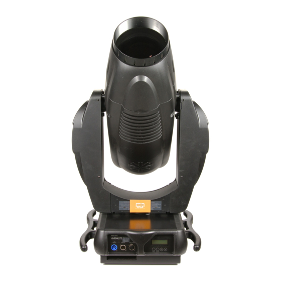
OMPONENTS XTERNAL UMINAIRE OMPONENTS Components External Luminaire Components The following illustration shows the external luminaire components and controls. Head Assembly Houses color, gobos, strobe, iris and zoom lens mechanisms Backcap Assembly Provides access to lamp for replacement and provides controls for beam adjustment. -
Page 24: Head And Yoke Components
❋ VARI LITE - VL3015LT S UMINAIRE ERVICE ANUAL Head and Yoke Components The following illustration shows the major sub-assemblies which are located in the luminaire head and yoke assemblies. Spot Optics Assembly Rotating Gobo Assembly Houses zoom lenses Contains three rotating gobo and edge mechanisms. -
Page 25: Enclosure Components
OMPONENTS NCLOSURE OMPONENTS Enclosure Components The following illustration shows the major sub-assemblies which are located in the luminaire enclosure assembly. (Yoke and head assemblies not shown for clarity.) Universal Arc Ballast Luminaire Handles Module 1200W / 1650W Pan Tube Assembly Fan Assembly Enclosure Top Covers 36 VDC / Low-Voltage... -
Page 26: Principles Of Operation
❋ VARI LITE - VL3015LT S UMINAIRE ERVICE ANUAL Principles of Operation Functional Block Diagram ZOOM / EDGE HEAD / YOKE OPTICS ASSEMBLIES DAUGHTER NOTE: COLOR Information contained herein is for reference only and may be changed at anytime without notice. -
Page 27: Chapter 2. Maintenance
HAPTER Maintenance This chapter contains test, service, and standard maintenance procedures. • Testing • Troubleshooting • Maintenance Procedures WARNING: All maintenance procedures are to be performed with power removed from the luminaire. Never remove cover or backcap while lamp is in oper- ation. -
Page 28: Luminaire Self-Tests
The luminaire is capable of running self tests by using the TEST menu functions. For detailed instructions regarding the luminaire’s self-test function, refer to the VL3015LT Spot Luminaire User’s Manual (02.9698.0002). This manual is available on the Vari-Lite web site, in the product download section, at www.vari-lite.com. -
Page 29: Auto Recalibration
Hold DMX value 140 for 3 seconds then 0 recals Dimmer and Strobe Sensor Testing Most mechanisms within the VL3015LT Spot Luminaires are equipped with either optical or magnetic sensors. The VL3015LT Spot Luminaire master control board (MCB) has labeled test points for reading DC voltages at each sensor. - Page 30 (refer to the VL3015LT Spot Luminaire User's Manual). On at full power will be one-half (1/2) PWM (which will meter at approximately 2vdc). On at Medium Power (1200W) will be no PWM signal (0vdc).
-
Page 31: Troubleshooting Error Messages
ROUBLESHOOTING RROR ESSAGES Troubleshooting Error Messages If a problem occurs during luminaire calibration, at the end of the calibration sequence the Menu Display will cycle through any applicable error message(s) until the end of the list is reached. To review the error messages again, it will be necessary to access them using the Status function. To access error messages: Step 1. -
Page 32: Troubleshooting Guide
❋ VARI LITE - VL3015LT S UMINAIRES ERVICE ANUAL Troubleshooting Guide If a problem is suspected, try recalibrating the luminaire to prompt an error message. Refer to “Error Messages” on page 13 for more information. The chart below provides possible causes and remedies for each message. - Page 33 ROUBLESHOOTING ROUBLESHOOTING UIDE Table 2-2: Troubleshooting Guide (Continued) Message Symptom Description Possible Cause and Remedy Tilt No Luminaire will not tilt Tilt Sensor Not Found EOT flag attached to large pulley is not engaging the Sens EOT sensor... - ensure flag is attached to the large pulley. - ensure that flag passes through the sensor at a depth sufficient to engage the sensor beam.
-
Page 34: Maintenance Procedures
❋ VARI LITE - VL3015LT S UMINAIRES ERVICE ANUAL Maintenance Procedures WARNING: As with any repairs or maintenance to VARI❋LITE luminaires, service should only be performed by a trained and qualified service technician or at an Authorized VARI❋LITE Service facility. -
Page 35: Align Lamp
Align Lamp The design of the VL3015LT Spot Luminaire optical system allows for a flat or peaked field. A flat field is one where there is no detectable hot spot and a peaked field is one where the intensity of the beam is greater at the center of the beam than at the perimeter. -
Page 36: Gobo Replacement - Gobo Wheels 1, 2, And 3
Overview of Gobos and Gags used in VL3015LT Spot Luminaire Due to the immense energy and light produced by VL3015LT spot luminaires, Vari-Lite recommends to users and owners of this fixture follow the guidelines outlined below when loading gobos or gags in any of the three rotating gobo wheels. - Page 37 1, 2, AINTENANCE ROCEDURES EPLACEMENT HEELS To Install or Replace Gobos WARNING: Remove power from luminaire before performing maintenance. Gobos may be HOT after operation. Allow to cool before replacing. To replace a rotating gobo: Step 1. Remove power from luminaire. Step 2.
- Page 38 ❋ VARI LITE - VL3015LT S UMINAIRES ERVICE ANUAL Step 3. If removing gobos via bottom of head assembly, undo fan tray assembly with thumb screw to access. Step 4. Rotate desired gobo wheel until required gobo position is accessible.
-
Page 39: Fixed Color Filter Replacement
AINTENANCE ROCEDURES IXED OLOR ILTER EPLACEMENT Fixed Color Filter Replacement Tools: #2 Phillips Screwdriver and Lint Free Cotton Gloves WARNING: Remove power from luminaire before performing maintenance. Filters may be HOT after operation. Allow to cool before replacing. To replace a fixed color filter on Color Wheel 1 (closest to the lamp): Step 1. - Page 40 ❋ VARI LITE - VL3015LT S UMINAIRES ERVICE ANUAL Fixed Color Filter Replacement (continued) Step 6. Orienting coated side of filter towards lamp, slide new filter under the spring clip until it is securely retained by the lock pins. Step 7. Replace the head cover.
-
Page 41: Ballast Assembly Replacement
AINTENANCE ROCEDURES ALLAST SSEMBLY EPLACEMENT Ballast Assembly Replacement Vari-Lite Part No: 69.9679.1216 To remove and replace ballast assembly: Step 1. Remove power from luminaire. WARNING: You must remove all power from luminaire before performing maintenance. Fixture may be very HOT after operation. Allow it to cool completely before performing any maintenance. Step 2. - Page 42 ❋ VARI LITE - VL3015LT S UMINAIRES ERVICE ANUAL Step 9. At bottom of enclosure, disconnect exhaust fan cable. Step 10. At exhaust fan, remove four 8/32 x 3/8" screws. Remove exhaust fan from enclosure assembly. Step 11. At ballast, disconnect following cable assemblies: a.
-
Page 43: Color/Dimmer/Strobe Assembly Replacement
AINTENANCE ROCEDURES OLOR IMMER TROBE SSEMBLY EPLACEMENT Color/Dimmer/Strobe Assembly Replacement Vari-Lite Part No: 21.9698.0400 To remove and replace color/dimmer/strobe assembly: Step 1. Remove power from luminaire. WARNING: You must remove all power from luminaire before performing maintenance. Fixture may be very HOT after operation. Allow it to cool completely before performing any maintenance. Step 2. -
Page 44: Gobo/Iris Assembly Replacement
❋ VARI LITE - VL3015LT S UMINAIRES ERVICE ANUAL Gobo/Iris Assembly Replacement Vari-Lite Part No: 21.9698.0200 To remove and replace gobo/iris assembly: Step 1. Run Zoom to full forward position (DMX 255). Step 2. Remove power from luminaire. WARNING: You must remove all power from luminaire before performing maintenance. Fixture may be very HOT after operation. -
Page 45: Reflector / Uv Glass Assembly Replacement
/ UV G AINTENANCE ROCEDURES EFLECTOR LASS SSEMBLY EPLACEMENT Reflector / UV Glass Assembly Replacement Vari-Lite Part No: 42.9686.0120 (Reflector) Vari-Lite Part No: 21.9686.0606 (Assy, UV Glass) To remove and replace reflector / UV glass assembly: Step 1. Disconnect luminaire AC input cable from power source. WARNING: You must remove all power from luminaire before performing maintenance. - Page 46 ❋ VARI LITE - VL3015LT S UMINAIRES ERVICE ANUAL Reflector Replacement (continued) Disconnect Springs Reflector Clamp UV/Reflector Assembly 4-40 x 1 3/8" screws (4) Assembly Removal Spring not shown for clarity Reflector Alignment Figure 2-10: Reflector / UV Glass Assembly Removal...
-
Page 47: Main Control Board (Mcb) Replacement
(MCB) R AINTENANCE ROCEDURES ONTROL OARD EPLACEMENT Main Control Board (MCB) Replacement Vari-Lite Part No: 24.9698.0700 To remove and replace main control board (MCB): Step 1. Remove power from luminaire. WARNING: You must remove all power from luminaire before performing maintenance. Fixture may be very HOT after operation. -
Page 48: Ignitor Board Replacement
❋ VARI LITE - VL3015LT S UMINAIRES ERVICE ANUAL Ignitor Board Replacement Vari-Lite Part No: 24.9661.3126 To remove and replace ignitor board assembly: Step 1. Remove power from luminaire. WARNING: You must remove all power from luminaire before performing maintenance. Fixture may be very HOT after operation. -
Page 49: Fan Regulator Board Replacement
AINTENANCE ROCEDURES EGULATOR OARD EPLACEMENT Fan Regulator Board Replacement Vari-Lite Part No: 24.9698.1690 To remove and replace fan regulator board: Step 1. Remove power from luminaire. WARNING: You must remove all power from luminaire before performing maintenance. Fixture may be very HOT after operation. Allow it to cool completely before performing any maintenance. Note: To determine which yoke leg is which without having to remove the covers, rotate yoke counterclockwise until it stops, then look at the luminaire while facing the input panel. -
Page 50: Interconnect Pcb Assembly Replacement
❋ VARI LITE - VL3015LT S UMINAIRES ERVICE ANUAL Interconnect PCB Assembly Replacement Vari-Lite Part No: 24.9698.2680 To remove and replace interconnect PCB assembly board: Step 1. Remove power from luminaire. WARNING: You must remove all power from luminaire before performing maintenance. Fixture may be very HOT after operation. -
Page 51: Zoom Optics Assembly Replacement
AINTENANCE ROCEDURES PTICS SSEMBLY EPLACEMENT Zoom Optics Assembly Replacement Vari-Lite Part No: 21.9698.0100 To remove and replace zoom optics assembly: Step 1. Remove power from luminaire. WARNING: You must remove all power from luminaire before performing maintenance. Fixture may be very HOT after operation. Allow it to cool completely before performing any maintenance. Step 2. -
Page 52: Frost / Prism Assembly Replacement
❋ VARI LITE - VL3015LT S UMINAIRES ERVICE ANUAL Frost / Prism Assembly Replacement Vari-Lite Part No: 21.9698.1351 To remove and replace frost / prism assembly: Step 1. Remove power from luminaire. WARNING: You must remove all power from luminaire before performing maintenance. Fixture may be very HOT after operation. -
Page 53: Zoom Optics / Frost / Prism - Cable Routing Reference
AINTENANCE ROCEDURES PTICS ROST RISM ABLE OUTING EFERENCE Zoom Optics / Frost / Prism - Cable Routing Reference The photos and descriptions below show cable routing in and around the zoom optics, frost, and prism assemblies. For additional information or assistance, please contact Vari-Lite Technical support. This section contains information for: •... - Page 54 ❋ VARI LITE - VL3015LT S UMINAIRES ERVICE ANUAL Lens Group A Motor Cable The motor cable for lens group A should be tied directly off onto the mount. There should be slack. Lens Group Motor Cables Tie off along mount as shown. When all lenses are pushed back, a little slack should still exist in cables to allow free mechanism movement.
- Page 55 AINTENANCE ROCEDURES PTICS ROST RISM ABLE OUTING EFERENCE Prism Sensor Cable Prism sensor cable should be secured next to motor connection and under motor as shown. After securing cables, insure prism assembly moves freely (in and out) without coming into contact with cables. Frost Sensor Cable Frost sensor cable should be secured next to motor connection and under motor as shown.
-
Page 56: Zoom Optics - Zoom (Actuator) Motor Replacement
❋ VARI LITE - VL3015LT S UMINAIRES ERVICE ANUAL Zoom Optics - Zoom (Actuator) Motor Replacement Vari-Lite Part No: 44.9698.0147 (Motor Assembly) Vari-Lite Part No: 10.9698.0146 (Shaft) To remove and replace a zoom actuator motor: Step 1. Remove power from luminaire. - Page 57 AINTENANCE ROCEDURES PTICS CTUATOR OTOR EPLACEMENT Step 5. Using slotted screwdriver to hold lead screw at front (DO NOT USE PLIERS ON LEAD SCREW OR YOU MAY DAMAGE IT!) remove two 8-32 KEPS nuts. Step 6. Carefully thread lead screw out of motor to be replaced. Note, you may have to thread out of other motors first, depending on which you are replacing.
-
Page 58: Tilt Motor Assembly And Tilt Belt Replacement
❋ VARI LITE - VL3015LT S UMINAIRES ERVICE ANUAL Tilt Motor Assembly and Tilt Belt Replacement Vari-Lite Part No: 21.9698.0765 (Tilt Motor) Vari-Lite Part No: 54.9698.0224 (Tilt Belt) To remove and replace tilt motor: Step 1. Remove power from luminaire. - Page 59 AINTENANCE ROCEDURES OTOR SSEMBLY AND EPLACEMENT WARNING: Make sure wiring is not pinched during installation. When tightening four 10-32 x 1/2" PPZ screws that mount Pan Motor Assembly, you must tighten in a CLOCKWISE pattern starting with screw in lower left-hand side from spring. NOTE: Head not shown for clarity.
-
Page 60: Tilt Encoder Pcb Replacement
❋ VARI LITE - VL3015LT S UMINAIRES ERVICE ANUAL Tilt Encoder PCB Replacement Vari-Lite Part No: 24.9661.5000 To remove and replace tilt encoder PCB: Step 1. Remove power from luminaire. WARNING: You must remove all power from luminaire before performing maintenance. Fixture may be very HOT after operation. -
Page 61: Tilt Eot Sensor Replacement
EOT S AINTENANCE ROCEDURES ENSOR EPLACEMENT Tilt EOT Sensor Replacement Vari-Lite Part No: 23.9661.1253 To remove and replace tilt EOT sensor: Step 1. Remove power from luminaire. WARNING: You must remove all power from luminaire before performing maintenance. Fixture may be very HOT after operation. Allow it to cool completely before performing any maintenance. Step 2. -
Page 62: Tilt Lock Replacement
❋ VARI LITE - VL3015LT S UMINAIRES ERVICE ANUAL Tilt Lock Replacement Vari-Lite Part No: 10.9698.1765 To remove and replace tilt lock: Step 1. Remove power from luminaire. WARNING: You must remove all power from luminaire before performing maintenance. Fixture may be very HOT after operation. -
Page 63: Pan Motor Assembly/Pan Belt Replacement
AINTENANCE ROCEDURES OTOR SSEMBLY EPLACEMENT Pan Motor Assembly/Pan Belt Replacement Vari-Lite Part No: 21.9698.0864 (Pan Motor) Vari-Lite Part No: 54.9698.0224 (Pan Belt) To remove and replace pan motor assembly: Step 1. Remove power from luminaire. WARNING: You must remove all power from luminaire before performing maintenance. Fixture may be very HOT after operation. - Page 64 ❋ VARI LITE - VL3015LT S UMINAIRES ERVICE ANUAL To remove and replace pan belt: Step 1. Remove power from luminaire. WARNING: You must remove all power from luminaire before performing maintenance. Fixture may be very HOT after operation. Allow it to cool completely before performing any maintenance.
-
Page 65: Pan Encoder Pcb Replacement
PCB R AINTENANCE ROCEDURES NCODER EPLACEMENT Pan Encoder PCB Replacement Vari-Lite Part No: 24.9678.5000 To remove and replace pan encoder PCB: Step 1. Remove power from luminaire. WARNING: You must remove all power from luminaire before performing maintenance. Fixture may be very HOT after operation. Allow it to cool completely before performing any maintenance. CAUTION: Be careful not to damage lens during next step. -
Page 66: Power Supply (Lvs) Replacement
❋ VARI LITE - VL3015LT S UMINAIRES ERVICE ANUAL Power Supply (LVS) Replacement Vari-Lite Part No: 69.9698.0036 To remove and replace LVS: Step 1. Remove power from luminaire. WARNING: You must remove all power from luminaire before performing maintenance. Fixture may be very HOT after operation. -
Page 67: Display Pcb Assembly Replacement
PCB A AINTENANCE ROCEDURES ISPLAY SSEMBLY EPLACEMENT Display PCB Assembly Replacement VL Part No: 24.9678.3825 To remove and replace display PCB assembly: Step 1. Remove power from luminaire. WARNING: You must remove all power from luminaire before performing maintenance. Fixture may be very HOT after operation. -
Page 68: Powercon Ac Input Connector Assembly Replacement
❋ VARI LITE - VL3015LT S UMINAIRES ERVICE ANUAL PowerCon AC Input Connector Assembly Replacement VL Part No: 25.9679.0001 To remove and replace PowerCon AC input connector assembly: Step 1. Remove power from luminaire. WARNING: You must remove all power from luminaire before performing maintenance. Fixture may be very HOT after operation. -
Page 69: Dmx Pcb Assembly Replacement
: DMX PCB A AINTENANCE ROCEDURES SSEMBLY EPLACEMENT DMX PCB Assembly Replacement VL Part No: 24.9664.4895 To remove and replace DMX PCB assembly: Step 1. Remove power from luminaire. WARNING: You must remove all power from luminaire before performing maintenance. Fixture may be very HOT after operation. -
Page 70: Upper Enclosure Fan Assembly Replacement
❋ VARI LITE - VL3015LT S UMINAIRES ERVICE ANUAL Upper Enclosure Fan Assembly Replacement VL Part No: 23.9698.0686 To remove and replace upper enclosure fan assembly: Step 1. Remove power from luminaire. WARNING: You must remove all power from luminaire before performing maintenance. Fixture may be very HOT after operation. -
Page 71: Fan Regulator Board (Upper Enclosure) Replacement
AINTENANCE ROCEDURES EGULATOR OARD PPER NCLOSURE EPLACEMENT Fan Regulator Board (Upper Enclosure) Replacement VL Part No: 24.9698.1690 To remove and replace fan regulator board in the upper enclosure: Step 1. Remove power from luminaire. WARNING: You must remove all power from luminaire before performing maintenance. Fixture may be very HOT after operation. -
Page 72: Pan Lock Replacement
❋ VARI LITE - VL3015LT S UMINAIRES ERVICE ANUAL Pan Lock Replacement VL Part No: 10.9698.0820 To remove and replace pan lock: Step 1. Remove power from luminaire. WARNING: You must remove all power from luminaire before performing maintenance. Fixture may be very HOT after operation. - Page 73 AINTENANCE ROCEDURES EPLACEMENT Step 7. At enclosure bottom, remove two 6-32 x 1/4" PPB screws and remove cover without handle. Step 8. Remove two 6-32 x 3/8" PFZ screws from enclosure side and remove Upper Enclosure Air Duct. Step 9. Remove two 10-32 Hex nuts holding pan lock in place. Note: When removing, note placement of springs, flat washers, glides, pan lock spring (especially note orientation) and pan lock cover.
-
Page 74: Gobo Timing Adjustments
❋ VARI LITE - VL3015LT S UMINAIRES ERVICE ANUAL Gobo Timing Adjustments The index timing belt must be aligned so that the mechanism "clocks" properly. This belt is installed around the index gear (top gear) of the gobo wheel. The wheel position belt is installed around the wheel position gear (bottom gear) of the gobo wheel, and does not require alignment. - Page 75 AINTENANCE ROCEDURES IMING DJUSTMENTS Gobo Timing Adjustments (continued) Position index pulley so large flange is centered in optical sensor Insert a 3" long #4 or M3 screw (or 0.125" diameter pin) completely through aligned holes in wheels and both bulkheads as shown. This will lock the wheels in the "open"...
-
Page 76: Gobo Gear Planet Alignment
❋ VARI LITE - VL3015LT S UMINAIRES ERVICE ANUAL Gobo Gear Planet Alignment Each gear of the gobo wheel assembly must be aligned so that the gobos will index correctly. Use the following procedure to re-align the gears in the event the gobo wheel is disassembled. -
Page 77: Gobo Gear Planet Alignment (Continued)
AINTENANCE ROCEDURES LANET LIGNMENT CONTINUED Gobo Gear Planet Alignment (continued) 1) Start with center gear timing 2) Rotate center gear clockwise until timing mark facing Position 1 (open). mark is directly across from Position 2. Rotate Position 2 gear until timing marks align. - Page 78 ❋ VARI LITE - VL3015LT S UMINAIRES ERVICE ANUAL Notes 02 .9 698.00 10 0...
-
Page 79: Chapter 3. Illustrated Parts Breakdown
HAPTER Illustrated Parts Breakdown This chapter contains illustrated parts breakdowns for all VL3015LT Spot Luminaire assemblies. • Drawing Trees • Top Assembly • Head Assembly • Yoke Assembly • Enclosure Assembly • Cable Assemblies 02.96 98.001 0 0... -
Page 80: Drawing Trees
21.9698.0311 Rev. G 21.9698.1351 Rev. E Ignitor to Lamp Socket Cable Assembly 25.9698.1688 Rev A Optics Bulkhead Cable Assembly 25.9698.1110 Rev B Continued Next Page Figure 3-1: VL3015LT Spot Luminaire Subassembly Drawing Tree Part 1 02 .9 698.00 10 0... - Page 81 Interconnect to Color Cable Assembly Yoke Fan to Volt Reg PCB Cable 25.9698.0410 Rev B Assembly 25.9698.0681 Rev B Upper Enclosure Assembly 21.9698.0800 Rev. N Continued Next Page Figure 3-2: VL3015LT Spot Luminaire Subassembly Drawing Tree Part 2 02.96 98.001 0 0...
- Page 82 25.9678.1825 Rev A Pan / Tilt Cable Assembly 25.9698.0801 Rev A Fan Exhaust Cable Assembly 25.9698.0832 Rev B Ballast Power Cable Assembly 25.9698.1003 Rev B Figure 3-3: VL3015LT Spot Luminaire Subassembly Drawing Tree Part 3 02 .9 698.00 10 0...
-
Page 83: Top Assembly
, VL3015LT S SSEMBLY NCLUDED TEMS Top Assembly Included Items Kit, VL3015LT Spot 28.9698.0001 Rev. F Refer to Figure 3-4. Item Qty. Description 02.8001.0002 VARI-LITE QUALITY ASSURANCE CERT. 02.8052.0001 CARD, LIMITED WARRANTY 02.8406.0001 TAG, LAMP NOTICE 02.8700.0001 CARD, PRODUCT REGISTRATION 02.9698.0001... - Page 84 Pebbles Uneven Bars Figure 3-4: Included Items Kit, VL3015LT Spot Note: * = Do not handle lamp with bare hands. When handling, it is best to wear clean cotton gloves in order to keep the lamp’s glass as dirt and grease free as possible.
-
Page 85: Vl3015Lt Spot Luminaire
VL3015LT Spot Luminaire 20.9698.0001 Rev. N Refer to Figure 3-5 Item Qty. Description 04.9698.0061 LABEL, AC INPUT RATING VL3015LT (not shown) 10.9686.0617 YOKE CROSS MEMBER, HEAT SHIELD 10.9698.1679 MOUNT, TRANSFER FAN, LT 10.9698.2125 MOUNT, INTERCONNECT BOARD 12.9698.0614 PAINTED FRONT COVER, VL3015LT 12.9698.0732... - Page 86 ❋ VARI LITE - VL3015LT S UMINAIRE ERVICE ANUAL Item Qty. Description 55.2233.2001 DZUS RAPIER MINI CLIP-ON RETAINER 55.6677.0033 WASHER, 0.281" OD, 0.125" ID, 0.032" THK 22.9678.0693 ASSY, GOBO CLAMP 02 .9 698.00 10 0...
- Page 87 : VL3015LT S SSEMBLY UMINAIRE VL3015LT Spot Luminaire (continued) 2, 15 (x4) (x2) (x2) (x8) (x2) (x4) (x8) (x4) (x8) (x2) (x2) (x2) (x4) (x2) Figure 3-5: VL3015LT Spot Luminaire 02.96 98.001 0 0...
-
Page 88: Generic Luminaire Assembly
❋ VARI LITE - VL3015LT S UMINAIRE ERVICE ANUAL Generic Luminaire Assembly 21.9698.0010 Rev. M Refer to Figure 3-6 Item Qty. Description 10.9698.0002 GROMMET, PROTECT, 2.9 INCHES 10.9698.0701 YOKE ARM AIR PLENUM, MCB COOLING 10.9698.0768 FOAM SPRING, TILT LOCK 10.9698.0769 STANDOFF, TILT LOCK 10.9698.1766... - Page 89 SSEMBLY ENERIC UMINAIRE SSEMBLY Item Qty. Description 55.6677.0045 WASHER, 0.260"ID, 0.500"OD, 0.030" THK 55.6799.0001 SHIM, 1-3/8" ID 1-7/8"OD, 0.010" THK, SS 55.6799.0002 SHIM, 1-3/8" ID 1-7/8"OD, 0.005" THK, SS 02.96 98.001 0 0...
- Page 90 ❋ VARI LITE - VL3015LT S UMINAIRE ERVICE ANUAL Generic Luminaire Assembly (continued) (x8) (x4) (x4) (x4) (x2) (x4) (x2) (x2) (x3) Detail (x2) (x2) (x2) Detail (x2) (x2) Detail A (x5), (x5) (x4) Note position and orientation of safety tether.
-
Page 91: Head Cover Assembly
BRACKET, COVER TETHER 10.9698.0612 FOAM BAFFLE, HEAD COVER 10.9698.0696 FOAM FRAME, HEAD COVER 12.9698.0610 PAINTED HEAD COVER, VL3015LT 53.5655.0250 SCREW, #6 X 1/4" PPZ PLASTIC THD 53.6558.0003 SCREW, 6-32 X 3/8" PPZ PLASTIC THD 55.2233.2003 DZUS RAPIER 1/4-TURN STUD RETAINER, 5 MM 55.2233.2008... -
Page 92: Gobo Clamp (With Cover Support) Assembly
❋ VARI LITE - VL3015LT S UMINAIRE ERVICE ANUAL Gobo Clamp (with Cover Support) Assembly 22.9698.0693 Rev A Refer to Figure 3-8 Item Qty. Description 10.9698.0626 COVER SUPPORT, CLAMP 12.9678.0691 GOBO CLAMP 53.6525.0188 SCREW, 6-32 X 3/16" LG PPZ SEMS 53.6685.0625... -
Page 93: Gobo Clamp Assembly
SSEMBLY LAMP SSEMBLY Gobo Clamp Assembly 22.9678.0693 Rev A Refer to Figure 3-9 Item Qty. Description 12.9678.0691 GOBO CLAMP 53.6685.0625 SCREW, CAPTIVE PANEL, 6-32 X 0.625"LG PPS ZINC PLATED 55.6538.0001 WASHER, #6 LOCK INTERNAL TOOTH 53.6613.1126 SCREW, 6-32 X 1.125 LG PPZ (x2) (x2) * Note: Install item 4 with Loctite 242. -
Page 94: Color Clamp Assembly
❋ VARI LITE - VL3015LT S UMINAIRE ERVICE ANUAL Color Clamp Assembly 22.9678.0694 Rev A Refer to Figure 3-10 Item Qty. Description 12.9678.0692 COLOR CLAMP 53.6685.0625 SCREW, CAPTIVE PANEL, 6-32 X.625" LG PPS ZINC PLATED 55.6538.0001 WASHER, #6 LOCK INTERNAL TOOTH 53.6613.1126... -
Page 95: Head Assembly
SSEMBLY TRUCTURE SSEMBLY Head Assembly Head Structure Assembly 21.9698.0600 Rev. E Refer to Figure 3-11 Item Qty. Description 10.9698.0627 COVER SUPPORT, SIDE RAIL 12.9698.0623 SIDE RAIL, MACHINED 12.9698.0625 SIDE RAIL, MACHINED 21.9686.0605 ASSY, REFLECTOR MOUNT 21.9698.0100 ASSY, LT OPTICS 21.9698.0615 ASSY, BACK END 53.6515.0001 SCREW, 10-32 X 3/4, SCB... - Page 96 ❋ VARI LITE - VL3015LT S UMINAIRE ERVICE ANUAL Head Structure Assembly (continued) (x4) (x6) (x2) (x8) (x4) (x4) Figure 3-11: Head Structure Assembly 02 .9 698.00 10 0...
-
Page 97: Reflector Mount Assembly
SSEMBLY EFLECTOR OUNT SSEMBLY Reflector Mount Assembly 21.9686.0605 Rev. D Refer to Figure 3-12 Item Qty. Description 10.9686.0632 REFLECTOR CLAMP 10.9686.0644 SPRING, REFLECTOR MOUNT 21.9686.0606 ASSY, UV GLASS 42.9686.0120 REFLECTOR, ELLIPTICAL 53.6683.0015 SCREW, 6-32 X 5/8" PPB SEMS (x4) (x4) Figure 3-12: Reflector Mount Assembly 02.96 98.001 0 0... -
Page 98: Vl3015Lt Optic Assembly
22.9698.0152 LENS ASSY, GROUP 2 22.9698.0153 LENS ASSY, GROUP 3 22.9698.0154 LENS ASSY, GROUP 4 10.9698.0146 SHAFT, ZOOM MOTOR ASSY, VL3015LT 44.9698.0147 MOTOR ASSY, ZOOM ACTUATOR 25.9698.1110 CABLE ASSY, OPTICS BULKHEAD (not shown) 53.2004.0002 NUT, 8-32 KEPS ZINC PLATED 53.2202.0008 NUT, 8-32 HEX SS NYLON INSERT 53.6513.0023... - Page 99 : VL3015LT O SSEMBLY PTIC SSEMBLY Item Qty. Description 53.6576.0038 SCREW, M3 X 8 MM PPZ SEMS 53.6594.0003 SCREW, 10-32 X 1.50" PPZ 53.6609.0001 SCREW, 6-32 X 3/8" PFZ 53.6682.0025 SCREW, 8-32 X 5/8" PPZ SEMS 55.2178.0001 CABLE ANCHOR MOUNT, #8 SCREW...
- Page 100 Cure with one pass through UV oven. Tighten second nut against first as jam nut. Figure 3-13: VL3015LT Optic Assembly 02 .9 698.00 10 0...
-
Page 101: Frost / Prism Bulkhead Assembly
SSEMBLY ROST RISM ULKHEAD SSEMBLY Frost / Prism Bulkhead Assembly 21.9698.1351 Rev. E Refer to Figure 3-14 Item Qty. Description 10.9698.0335 DAMPER, MOTOR SHAFT, 5 MM 10.9698.2301 FROST/PRISM DUAL MOUNT, LENS GROUP B 21.9698.0311 ASSY, PRISM 21.9698.0321 ASSY, FROST 24.9698.1231 PCB ASSY, SENSOR 44.9676.0117 MOTOR, GOBO ROTATE/INDEX... - Page 102 ❋ VARI LITE - VL3015LT S UMINAIRE ERVICE ANUAL Frost / Prism Bulkhead Assembly (continued) **Tighten screw firmly until gap in damper is closed completely. 8** (x2) (x2) (x4) (x2) 9* (x2) 11* (x4) 10* (x6) *Apply Loctite 242 to fastener at assembly.
-
Page 103: Prism Assembly
SSEMBLY RISM SSEMBLY Prism Assembly 21.9698.0311 Rev. G Refer to Figure 3-15 Item Qty. Description 10.9698.0331 SPACER, TEFLON, PRISM 10.9698.0332 BEARING, BORE, TEFLON 10.9698.0334 RETAINING RING, PRISM 10.9698.1468 PULLEY, MOTOR, PRISM DRIVE 10.9698.2173 MOUNT, PRISM, MACHINED 10.9698.2312 ARM, PRISM 22.9698.0318 ASSY, PRISM ROTATOR 44.9687.1218 MOTOR, SIZE-14, LO-PRFL, 0.9 DEG... - Page 104 ❋ VARI LITE - VL3015LT S UMINAIRE ERVICE ANUAL Prism Assembly (continued) (x3) Figure 3-15: Prism Assembly 02 .9 698.00 10 0...
-
Page 105: Backend Assembly
SSEMBLY ACKEND SSEMBLY Backend Assembly 21.9698.0615 Rev J Refer to Figure 3-16 Item Qty. Description 10.9678.0653 LIGTH BAFFLE, EXHAUST 10.9678.1649 FAN SHIELD, LAMP COOLING, DC 10.9686.0659 FAN INSULATOR, THIN 10.9698.0637 REFLECTOR ACCESS, AIR DIVERTER 10.9698.0638 AIR DIVERTER, STROBE MOTOR 10.9698.0639 0.312"... - Page 106 ❋ VARI LITE - VL3015LT S UMINAIRE ERVICE ANUAL Item Qty. Description 55.6541.0008 GROMMET, 1/2"ID 7/8"OD 11/32"T 55.6677.0042 0.50" OD TEFLON WASHER 55.6706.0001 GROMMET, 9/32" ID, 9/16" OD, 1/4" THK SI 74.1099.0001 SWITCH, MINIATURE, 150-DEG, 5 AMP 02 .9 698.00 10 0...
- Page 107 SSEMBLY ACKEND SSEMBLY Backend Assembly (continued) (x8) (x2) (x2) (x2) (x2) (x4) (x4) (x2) (x4) (x2), (x4) (x4) See Detail A (x10) (x4) (x4) (x2) (x2) (x2) (x2) Detail A 5 Ref. Figure 3-16: Backend Assembly 02.96 98.001 0 0...
-
Page 108: Hot Box Assembly
❋ VARI LITE - VL3015LT S UMINAIRE ERVICE ANUAL Hot Box Assembly 21.9686.0680 Rev H Refer to Figure 3-17 Item Qty. Description 10.9678.0043.04 LABEL PLATE, VL3500 WASH BACKCAP, BLACK 10.9686.0642 BACKCAP PLATE 10.9678.0643 LAMP ADJUST STOP 10.9678.0645 KNOB, LAMP ADJ MOLDED 10.9686.0681... - Page 109 SSEMBLY SSEMBLY Hot Box Assembly (continued) (x2) (x3) (x8) (x4) (x3) (x3) (x4) (x3) Figure 3-17: Hot Box Assembly 02.96 98.001 0 0...
-
Page 110: 80Mm Dc Fan Assembly
❋ VARI LITE - VL3015LT S UMINAIRE ERVICE ANUAL 80MM DC Fan Assembly 21.9698.0616 Rev B Refer to Figure 3-18 Item Qty. Description 40.7113.1010 FAN, TUBAXIAL, 80MM, 24VDC, LONG LIFE WITH TACH 53.2002.0001 NUT, 6-32, KEPS ZINC 53.6558.0001 SCREW, 6-32 X 3/8" LG PPZ 55.7016.0001... -
Page 111: Color / Gobo Access Fan Assembly
SSEMBLY OLOR CCESS SSEMBLY Color / Gobo Access Fan Assembly 21.9698.0620 Rev E Refer to Figure 3-19 Item Qty. Description 10.9678.1649 FAN SHIELD, LAMP COOLING, DC 10.9698.0665 FAN TRAY, COLOR/GOBO COOLING 10.9698.0666 STIFFENER PLATE, FAN TRAY 23.9679.0016 FAN, TUBAZIAL, 80MM, 24VDC, LAMP COOLING, LONG LIFE 53.6530.0011 RIVET, POP, 1/8"... - Page 112 ❋ VARI LITE - VL3015LT S UMINAIRE ERVICE ANUAL Notes 02 .9 698.00 10 0...
-
Page 113: Gobo Module Assembly
SSEMBLY ODULE SSEMBLY Gobo Module Assembly 21.9698.0200 Rev H Refer to Figure 3-20 Item Qty. Description 10.9678.0225 SHAFT, GOBO WHEEL 10.9678.0231 MOTOR PULLEY W/ FLANGES 10.9678.0232 PULLEY, GOBO DRIVE 10.9678.0244 MOUNT, INDEX SENSOR, LONG 10.9678.0245 MOUNT, INDEX SENSOR, SHORT 10.9678.0246 MOTOR ADJUST PLATE 10.9678.0277 SPACER, WHEEL/IRIS... - Page 114 ❋ VARI LITE - VL3015LT S UMINAIRE ERVICE ANUAL Item Qty. Description 55.2110.0002 WASHER, 0.400" OD 0.260" ID 0.010" THK 55.2150.0002 STANDOFF, 1/4" HEX 6-32 X 1.187" MF 55.2150.0003 STANDOFF, 1/4" HEX 6-32 1.125" L 55.2178.0001 CABLE ANCHOR MOUNT, #8 SCREW MOUNTING 55.6506.0025...
- Page 115 SSEMBLY ODULE SSEMBLY Gobo Module Assembly (continued) (x10) (x12) (x2) (x3) (x6) (x4) (x16) (x4) (x2) (x8) (x2) (x3) (x4) (x4) (x3) (x3) (x4) (x6) (x3) (x3) (x3) Figure 3-20: Gobo Module Assembly 02.96 98.001 0 0...
-
Page 116: Rotating Gobo Wheel Assembly
❋ VARI LITE - VL3015LT S UMINAIRE ERVICE ANUAL Rotating Gobo Wheel Assembly 21.9698.0211 Rev B Refer to Figure 3-21 Item Qty. Description 10.9663.1211 SPACER, TEFLON, GOBO GEAR 10.9663.1240 BEARING, GOBO WHEEL BORE 10.9678.0221 PLATE, ROTATING EFFECTS WHEEL 10.9678.0224 RETAINING RING, PLANET 10.9678.0250... -
Page 117: Iris Sub-Assembly
SSEMBLY SSEMBLY Iris Sub-Assembly 21.9698.0270 Rev H Refer to Figure 3-22 Item Qty. Description 10.9678.0273 MOTOR MOUNT, IRIS 10.9698.0272 BULKHEAD, IRIS 10.9698.0278 AIR DIVERTER, GOBO 10.9698.0279 DIVERTER, GOBO AIR 10.9698.0280 ADJUSTABLE IRIS STOP 10.9698.1276 CRANK, IRIS, LT 22.9698.0271 LINK ASSY, IRIS - 53.6605.0004 STUD, 2-56 X 1.0"... - Page 118 ❋ VARI LITE - VL3015LT S UMINAIRE ERVICE ANUAL Iris Sub-Assembly (continued) (x3) (x2) (x2) (x4) (x3) See Detail A (x4) (x4) Detail A (x2) (x2) 0.50 in. +/- 0.03 in. Align flat sides of 1.78 in. both links as...
-
Page 119: Color/Strobe Module Assembly
SSEMBLY OLOR TROBE ODULE SSEMBLY Color/Strobe Module Assembly 21.9698.0400 Rev E Refer to Figure 3-20 Item Qty. Description 10.9678.0246 MOTOR ADJUST PLATE 10.9686.0446 ADJUST PLATE, MOTOR 10.9686.1468 MOTOR PULLEY WITH FLANGES 10.9686.2457.02 SPACER, COLOR WHEEL 10.9686.2457.04 SPACER, COLOR WHEEL 10.9686.2457.07 SPACER, COLOR WHEEL 10.9698.0246 ADJUST PLATE, CURVED, MOTOR... - Page 120 ❋ VARI LITE - VL3015LT S UMINAIRE ERVICE ANUAL Item Qty. Description 44.9663.1766 ZOOM/DIMMER MOTOR 44.9698.1203 MOTOR, 17, 2.42" SHAFT 11.8 MH 53.6525.0188 SCREW, 6-32 X 3/16" LG PPZ SEMS 53.6530.0013 RIVET, 1/8" CSK, 0.25 GRP 53.6558.0009 SCREW, 6-32 X 3/8" PPZ SEMS 53.6609.0001...
- Page 121 SSEMBLY OLOR TROBE ODULE SSEMBLY Color Module Assembly (continued) (x4) (x8) (x6) (x14) Magenta Yellow Cyan Dimmer (x18) (x6) (x2) (x8) (x7) (x5) (x4) (x3) (x2) (x4) (x2) Figure 3-23: Color Module Assembly 02.96 98.001 0 0...
-
Page 122: Strobe System Assembly
❋ VARI LITE - VL3015LT S UMINAIRE ERVICE ANUAL Strobe System Assembly 21.9698.2404 Rev D Refer to Figure 3-24 Item Qty. Description 10.9678.0491 BUMPER STOP, STROBE BLADE, TEFLON 10.9698.1450 REFLECTOR, STROBE BULKHEAD 10.9698.2435 BULKHEAD, STROBE, SINGLE SIDED 21.9698.2437 ASSY, STROBE BLADE, TOP 21.9698.2438... - Page 123 SSEMBLY TROBE YSTEM SSEMBLY Strobe System Assembly (continued) (x2) (x4) *Apply Loctite 242 thread locker to strobe blade set screws and 272 to bumper stop screws. (x8) 9* (x2) Side View (x8) (x2) (x2) (x8) (x4) (x8) (x2) 9* (x2) (x8) Figure 3-24: Strobe System Assembly 02.96 98.001 0 0...
-
Page 124: Top Strobe Blade Assembly
❋ VARI LITE - VL3015LT S UMINAIRE ERVICE ANUAL Top Strobe Blade Assembly 21.9698.2437 Rev B Refer to Figure 3-25 Item Qty. Description 10.9678.0432 HUB, STROBE BLADE 10.9678.0466 STROBE BLADE, DAMPER 10.9698.2432 STROBE BLADE, NOTCHED 53.5559.0250 SCREW, 6-32 X 1/4" SET CONE PO 53.6597.0001... -
Page 125: Bottom Strobe Blade Assembly
SSEMBLY OTTOM TROBE LADE SSEMBLY Bottom Strobe Blade Assembly 21.9698.2438 Rev B Refer to Figure 3-26 Item Qty. Description 10.9678.0432 HUB, STROBE BLADE 10.9678.0466 STROBE BLADE DAMPER 10.9698.2431 STROBE BLADE, NOTCHED 53.5559.0250 SCREW, 6-32 X 1/4" SET CONE PO 53.6597.0001 SCREW, 4-40 X 3/16"... -
Page 126: Fixed Color Wheel 2 Assembly
❋ VARI LITE - VL3015LT S UMINAIRE ERVICE ANUAL Fixed Color Wheel 2 Assembly 21.9686.1480 Rev A Refer to Figure 3-27 Item Qty. Description 10.9686.0481 WHEEL, FIXED COLOR 10.9686.0482 SPACER PLATE, FIXED COLOR 10.9686.0483 SPRING PLATE, FIXED COLOR 22.9686.1416 FIXED COLOR WHEEL HUB WITH BEARINGS 41.9686.0495... - Page 127 SSEMBLY IXED OLOR HEEL SSEMBLY Fixed Color Wheel 2 Assembly (continued) Detail A (x4) POS 1 OPEN Note: All filters must be installed with the coating side towards the luminaire’s lamp. Open Blue Green Orange Amber Alignment Tab Dark Fuchsia Detail A Alignment Tab RTV beads should be applied at all...
-
Page 128: Fixed Color Wheel 1 Assembly
❋ VARI LITE - VL3015LT S UMINAIRE ERVICE ANUAL Fixed Color Wheel 1 Assembly 21.9698.1484 Rev B Refer to Figure 3-28 Item Qty. Description 10.9686.0481 WHEEL, FIXED COLOR 10.9686.0482 SPACER PLATE, FIXED COLOR 10.9686.0483 SPRING PLATE, FIXED COLOR 22.9686.1416 FIXED COLOR WHEEL HUB WITH BEARINGS 41.9686.0490... - Page 129 SSEMBLY IXED OLOR HEEL SSEMBLY Fixed Color Wheel 1 Assembly (continued) Detail A (x4) POS 1 OPEN Note: All filters must be installed with the coating side towards the luminaire’s lamp. Open Congo Blue Alignment Tab Kelly Yellow Green Magenta Detail A Alignment Tab RTV beads should be applied at all...
- Page 130 ❋ VARI LITE - VL3015LT S UMINAIRE ERVICE ANUAL Notes 02 .9 698.00 10 0...
-
Page 131: Yoke Assembly Yoke Assembly
SSEMBLY SSEMBLY Yoke Assembly Yoke Assembly 21.9698.0700 Rev G Refer to Figure 3-29 Item Qty. Description 10.9678.0756 IGNITOR SHIELD 10.9678.0764 PLATE, TILT ENCODER MOUNT 21.9698.0765 ASSY, TILT MOTOR 22.9661.0609 ASSY, YOKE FAN 22.9698.1705 ASSY, YOKE STRUCTURE 23.9661.1253 ELEC ASSY, PAN EOT SENSOR 23.9650.3327 ELEC ASSY, RELAY 24.9661.3126... - Page 132 ❋ VARI LITE - VL3015LT S UMINAIRE ERVICE ANUAL Yoke Assembly (continued) (x2) (x2) (x8) (x2) (x2) (x2) (x2) (x2) (x10) (x2) (x2) (x6) Figure 3-29: Yoke Assembly 02 .9 698.00 10 0...
-
Page 133: Tilt Motor Assembly
SSEMBLY OTOR SSEMBLY Tilt Motor Assembly 21.9698.0765 Rev D Refer to Figure 3-30 Item Qty. Description 10.9686.0457.05 SPACER, COLOR WHEEL 10.9698.0763 PLATE, TILT MOTOR MOUNT 10.9698.0861 PLATE, BELT GUIDE 10.9698.0835 STANDOFF, BELT GUIDE, TILT MOTOR ASSY 21.9698.0708 ASSY, DRIVE PULLEY - 10.9678.8720 CODEWHEEL, 120 COUNT, LARGE ID - 10.9698.1749... - Page 134 ❋ VARI LITE - VL3015LT S UMINAIRE ERVICE ANUAL Tilt Motor Assembly (continued) Detail A See Detail A (x2) (x2) (x2) (x6) (x4) (x2) (x2) (x2) Pressure-Sensitive Adhesive (x2) (x2) * As required to set proper height. Pulley Height Detail & Installation (x4) 0.239"...
-
Page 135: Yoke Fan Assembly
SSEMBLY SSEMBLY Yoke Fan Assembly 22.9661.0609 Rev D Refer to Figure 3-31 Item Qty. Description 10.9661.0646 FAN TRAY 40.7113.1001 FAN, +24V 80 X 80 X 25MM, 32CFM 53.2200.0006 NUT, 6-32 KEPS SS DIRECTION OF AIR FLOW (x4) Note fan wire orientation. Figure 3-31: Yoke Fan Assembly 02.96 98.001 0 0... - Page 136 ❋ VARI LITE - VL3015LT S UMINAIRE ERVICE ANUAL Notes 02 .9 698.00 10 0...
-
Page 137: Enclosure Assembly Upper Enclosure Assembly
NCLOSURE SSEMBLY PPER NCLOSURE SSEMBLY Enclosure Assembly Upper Enclosure Assembly 21.9698.0800 Rev. N Refer to Figure 3-32, Figure 3-33 Figure 3-34 Item Qty. Description 04.9640.0374 LABEL, GROUND 04.9698.0040 LABEL, VL3500 SERIES COMPLIANCE 10.9661.1358 AIR SEAL, DUCT 10.9678.0820 LANYARD, PAN TUBE 10.9678.0869 BRACKET, LVS 10.9678.0886... - Page 138 LITE - VL3015LT S UMINAIRE ERVICE ANUAL Item Qty. Description 22.9698.0690 ASSY, VL3015LT FAN VOLT. REG. UPPER ENCLOSURE 22.9698.0851 ASSY, UPPER ENCLOSURE STRUCTURE 23.9698.0686 FAN ASSY, UPPER ENCLOSURE 25.9661.1514 CABLE ASSY, LVS CHASSIS GND (EMI GND) (not shown) 25.9661.1520 CABLE ASSY, CHASSIS TO YOKE GND (not shown) 25.9678.0813...
- Page 139 NCLOSURE SSEMBLY PPER NCLOSURE SSEMBLY Item Qty. Description 53.6607.0001 SCREW, 6-32 X 1/4" PPB 53.6609.0001 SCREW, 6-32 X 3/8" PFZ 53.6626.0001 SCREW, 10-32 X 1/2" PPZ 53.6634.1000 SCREW, 3/8-16 X 1.00" LG SOC HD CAP ALLOY STEEL 53.6667.0005 SCREW, 10-32 X 3/8" LG SET CUP 53.7018.0750 SCREW, 1/4-20 X 0750"...
- Page 140 ❋ VARI LITE - VL3015LT S UMINAIRE ERVICE ANUAL Upper Enclosure Assembly (continued) (x2) (x2) (x5) (x4) (x2) (x2) (x4) (x4) (x4) Figure 3-32: Upper Enclosure Assembly Part 1 02 .9 698.00 10 0...
- Page 141 NCLOSURE SSEMBLY PPER NCLOSURE SSEMBLY Upper Enclosure Assembly (continued) Pan Tube Assembly (x3) (x4) (x2) (x4) (x2) Part is shown exploded for clarity (x4) (x2), (x2) (x2) (x4) (x2) (x4) (x2) (x2) (x2) (x4) (x2) (x3) (x3) (x2) (x3) Figure 3-33: Upper Enclosure Assembly Part 2 02.96 98.001 0 0...
- Page 142 ❋ VARI LITE - VL3015LT S UMINAIRE ERVICE ANUAL Upper Enclosure Assembly (continued) Electronics Assembly Detail A See Detail A (x7) (x3) (x3) (x2) (x4), (x4) (x2) (x4) Duct Assembly (x4) (x2) (x4) (x4) Ref. Figure 3-34: Upper Enclosure Assembly Part 3...
-
Page 143: Stabilizer Assembly
NCLOSURE SSEMBLY TABILIZER SSEMBLY Stabilizer Assembly 21.9678.0767 Rev 0 Refer to Figure 3-35 Item Qty. Description 10.9678.0757 STABILIZER, 1.377 DIA 10.9678.0762 BRACKET, STABILIZER 53.6610.0003 SCREW, 6-32 X 7/16" PPZ 55.6568.0075 SPRING, EXTN, 0.375" OD, 1.0" LG, 0.041" DIA, WIRE Figure 3-35: Stabilizer Assembly 02.96 98.001 0 0... -
Page 144: Pan Motor Assembly
❋ VARI LITE - VL3015LT S UMINAIRE ERVICE ANUAL Pan Motor Assembly 21.9698.0864 Rev E Refer to Figure 3-36 Item Qty. Description 10.9678.8720 CODEWHEEL, 120 COUNT, LARGE ID 10.9686.0457.01 SPACER, COLOR WHEEL 10.9686.0841 ADAPTOR PLATE, PAN SENSOR PCB 10.9686.0865 PLATE, TENSION ADJUST, PAN MOTOR 10.9698.1749... - Page 145 NCLOSURE SSEMBLY OTOR SSEMBLY Pan Motor Assembly (continued) Detail A (x2) Pressure-Sensitive Adhesive (x2) (x2) See Detail A (x6) (x4) Drive Pulley Detail & Installation (x2) 1.050" (x2) (x2) Step 1. Apply one drop of Loctite 603 to motor shaft. Step 2.
-
Page 146: Ventilation Cover Assembly
❋ VARI LITE - VL3015LT S UMINAIRE ERVICE ANUAL Ventilation Cover Assembly 21.9698.0840 Rev D Refer to Figure 3-37 Item Qty. Description 10.9661.1249 POST, TRUSS HOOK 10.9678.0835 AIR SEAL, SHORT SIDE 10.9678.0836 AIR SEAL, LONG SIDE 10.9678.0837 AIR SEAL, FAN SIDE 10.9678.0838... -
Page 147: Input Panel Assembly
NCLOSURE SSEMBLY NPUT ANEL SSEMBLY Input Panel Assembly 21.9698.0805 Rev C Refer to Figure 3-38 Item Qty. Description 10.9678.0872 STIFFENER, DISPLAY BOARD 10.9679.0850 BACKING PLATE, NEUTRIK 10.9698.0852 OVERLAY, INPUT PANEL, VL3015 10.9698.0859 BRACKET, INPUT 24.9663.1830 PCB ASSY, DMX INPUT 24.9678.3825 PCB ASSY, VL3000 DISPLAY 25.9679.0001 CONNECTOR, CHASSIS POWER, INLET 3-POLE LK... -
Page 148: Machined Pan Tube Assembly
❋ VARI LITE - VL3015LT S UMINAIRE ERVICE ANUAL Machined Pan Tube Assembly 21.9698.0881 Rev 0 Refer to Figure 3-39 Item Qty. Description 10.9678.0809 PAN TOGGLE STOP 10.9678.0847 SILICONE FOAM WASHER 10.9678.0848 WASHER, PAN TEFLON 12.9698.0877 PAN TUBE, MACHINED 54.1206.0021 RING, RETAINING, 1.562"... -
Page 149: High Flow Exhaust Fan Assembly
NCLOSURE SSEMBLY XHAUST SSEMBLY High Flow Exhaust Fan Assembly 21.9679.0811 Rev A Refer to Figure 3-40 Item Qty. Description 10.9686.0810 MOUNTING PLATE, EXHAUST FAN 40.9687.0001 BLOWER, CENTRIFUGAL, 24VDC 10.6 CFM, 3 IN 55.6576.0001 SCREW, #10-16 X 3/8" TYPE B PFZ (x2) Figure 3-40: High Flow Exhaust Fan Assembly 02.96 98.001 0 0... -
Page 150: Fan Regulator Board Assembly
22.9698.0690 Rev B Refer to Figure 3-41 Item Qty. Description 10.9686.0690 MOUNTING PLATE, FAN VOLTAGE REG. 24.9698.1690 PCB ASSY, VL3015LT FAN VOLTAGE REGULATOR 53.5504.0250 SCREW, 4-40 X 1/4" PPSS (x2) Figure 3-41: Fan Regulator Board Assembly 02 .9 698.00 10 0... -
Page 151: Section Is For Reference Only
: LVS C ABLE SSEMBLIES HASSIS ROUND ABLE SSEMBLY Cable Assemblies LVS Chassis Ground Cable Assembly 25.9661.1514 Rev A Refer to Figure 3-42 Figure 3-42: LVS Chassis Ground Cable Assembly Cables are only available as complete assemblies. The information contained in this Note: section is for reference only. -
Page 152: Chassis To Yoke Ground Cable Assembly
❋ VARI LITE - VL3015LT S UMINAIRE ERVICE ANUAL Chassis To Yoke Ground Cable Assembly 25.9661.1520 Rev C Refer to Figure 3-43 Figure 3-43: Chassis To Yoke Ground Cable Assembly Cables are only available as complete assemblies. The information contained in this Note: section is for reference only. -
Page 153: Head To Back Cap Ground Cable Assembly
ABLE SSEMBLIES EAD TO ROUND ABLE SSEMBLY Head to Back Cap Ground Cable Assembly 25.9661.1522 Rev C Refer to Figure 3-44. Figure 3-44: Head to Back Cap Ground Cable Assembly Cables are only available as complete assemblies. The information contained in this Note: section is for reference only. -
Page 154: Ignitor To Relay Cable Assembly
❋ VARI LITE - VL3015LT S UMINAIRE ERVICE ANUAL Ignitor to Relay Cable Assembly 25.9661.1526 Rev C Refer to Figure 3-45. Figure 3-45: Ignitor to Relay Cable Assembly Cables are only available as complete assemblies. The information contained in this Note: section is for reference only. -
Page 155: Yoke Fan Cable Assembly
ABLE SSEMBLIES ABLE SSEMBLY Yoke Fan Cable Assembly 25.9678.0758 Rev A Refer to Figure 3-46 Figure 3-46: Yoke Fan Cable Assembly Cables are only available as complete assemblies. The information contained in this Note: section is for reference only. 02.96 98.001 0 0... -
Page 156: Data I/O Link Cable Assembly
❋ VARI LITE - VL3015LT S UMINAIRE ERVICE ANUAL Data I/O Link Cable Assembly 25.9678.0813 Rev A Refer to Figure 3-47 Figure 3-47: Data I/O Link Cable Assembly Cables are only available as complete assemblies. The information contained in this Note: section is for reference only. -
Page 157: Ballast To Controller Cable Assembly
ABLE SSEMBLIES ALLAST TO ONTROLLER ABLE SSEMBLY Ballast to Controller Cable Assembly 25.9678.0816 Rev A Refer to Figure 3-48 Figure 3-48: Ballast to Controller Cable Assembly Cables are only available as complete assemblies. The information contained in this Note: section is for reference only. 02.96 98.001 0 0... -
Page 158: Lamp Supply To Relay Cable Assembly
❋ VARI LITE - VL3015LT S UMINAIRE ERVICE ANUAL Lamp Supply to Relay Cable Assembly 25.9678.0829 Rev A Refer to Figure 3-49 To Relay From Lamp Supply From Lamp Supply To Relay Figure 3-49: Lamp Supply to Relay Cable Assembly Cables are only available as complete assemblies. -
Page 159: Display Cable Assembly
ABLE SSEMBLIES ISPLAY ABLE SSEMBLY Display Cable Assembly 25.9678.1825 Rev A Refer to Figure 3-50 Figure 3-50: Display Cable Assembly Cables are only available as complete assemblies. The information contained in this Note: section is for reference only. 02.96 98.001 0 0... -
Page 160: Ac Input Connector/Cable Assembly
❋ VARI LITE - VL3015LT S UMINAIRE ERVICE ANUAL AC Input Connector/Cable Assembly 25.9679.0001 Rev 0 Refer to Figure 3-51 Figure 3-51: AC Input Cable Assembly Cables are only available as complete assemblies. The information contained in this Note: section is for reference only. -
Page 161: Iris Fan Cable Assembly
ABLE SSEMBLIES ABLE SSEMBLY Iris Fan Cable Assembly 25.9679.0007 Rev A Refer to Figure 3-52 Figure 3-52: Iris Fan Cable Assembly Cables are only available as complete assemblies. The information contained in this Note: section is for reference only. 02.96 98.001 0 0... -
Page 162: 36V Interconnect Cable Assembly
❋ VARI LITE - VL3015LT S UMINAIRE ERVICE ANUAL 36V Interconnect Cable Assembly 25.9698.0011 Rev 0 Refer to Figure 3-53 Figure 3-53: 36V Interconnect Cable Assembly Cables are only available as complete assemblies. The information contained in this Note: section is for reference only. -
Page 163: 36V Yoke Reg Pcb Cable Assembly
: 36V Y PCB C ABLE SSEMBLIES ABLE SSEMBLY 36V Yoke Reg PCB Cable Assembly 25.9698.0012 Rev A Refer to Figure 3-54 Figure 3-54: 36V Yoke Reg PCB Cable Assembly Cables are only available as complete assemblies. The information contained in this Note: section is for reference only. -
Page 164: 24V Relay To Interconnect Cable Assembly
❋ VARI LITE - VL3015LT S UMINAIRE ERVICE ANUAL 24V Relay to Interconnect Cable Assembly 25.9698.0015 Rev A Refer to Figure 3-55 Figure 3-55: 24V Relay to Interconnect Cable Assembly Cables are only available as complete assemblies. The information contained in this Note: section is for reference only. -
Page 165: Optics (Mcb To Interconnect) Cable Assembly
(MCB ABLE SSEMBLIES PTICS NTERCONNECT ABLE SSEMBLY Optics (MCB to Interconnect) Cable Assembly 25.9698.0109 Rev A Refer to Figure 3-56 Figure 3-56: Optics (MCB to Interconnect) Cable Assembly Cables are only available as complete assemblies. The information contained in this Note: section is for reference only. -
Page 166: Gobo (Mcb To Interconnect) Cable Assembly
❋ VARI LITE - VL3015LT S UMINAIRE ERVICE ANUAL Gobo (MCB to Interconnect) Cable Assembly 25.9698.0209 Rev B Refer to Figure 3-56 Figure 3-57: Gobo (MCB to Interconnect) Cable Assembly Cables are only available as complete assemblies. The information contained in this Note: section is for reference only. -
Page 167: Interconnect To Gobo Cable Assembly
ABLE SSEMBLIES NTERCONNECT TO ABLE SSEMBLY Interconnect to Gobo Cable Assembly 25.9698.0210 Rev B Refer to Figure 3-56 Figure 3-58: Interconnect to Gobo Cable Assembly Cables are only available as complete assemblies. The information contained in this Note: section is for reference only. 02.96 98.001 0 0... -
Page 168: Color (Mcb To Interconnect) Cable Assembly
❋ VARI LITE - VL3015LT S UMINAIRE ERVICE ANUAL Color (MCB to Interconnect) Cable Assembly 25.9698.0409 Rev C Refer to Figure 3-59 Figure 3-59: Color (MCB to Interconnect) Cable Assembly Cables are only available as complete assemblies. The information contained in this Note: section is for reference only. -
Page 169: Interconnect To Color Cable Assembly
ABLE SSEMBLIES NTERCONNECT TO OLOR ABLE SSEMBLY Interconnect to Color Cable Assembly 25.9698.0410 Rev B Refer to Figure 3-60 Figure 3-60: Interconnect to Color Cable Assembly Cables are only available as complete assemblies. The information contained in this Note: section is for reference only. 02.96 98.001 0 0... -
Page 170: Ot Switch To Backcap Interlok Cable Assembly
❋ VARI LITE - VL3015LT S UMINAIRE ERVICE ANUAL OT Switch to Backcap Interlok Cable Assembly 25.9698.0601 Rev B Refer to Figure 3-61 Figure 3-61: OT Switch to Backcap Interlok Cable Assembly Cables are only available as complete assemblies. The information contained in this Note: section is for reference only. -
Page 171: Transfer Fan To Interconnect Cable Assembly
ABLE SSEMBLIES RANSFER AN TO NTERCONNECT ABLE SSEMBLY Transfer Fan to Interconnect Cable Assembly 25.9698.0622 Rev D Refer to Figure 3-62 WIRE CHART WIRE CONN CONN FROM ITEM NO. ITEM NO. COLOR PIN 1 PIN 3 PIN 2 PIN 1 PIN 3 PIN 4 Figure 3-62: Transfer Fan to Interconnect Cable Assembly... -
Page 172: Lamp And Bulkhead Fans Cable Assembly
❋ VARI LITE - VL3015LT S UMINAIRE ERVICE ANUAL Lamp and Bulkhead Fans Cable Assembly 25.9698.0650 Rev A Refer to Figure 3-63 FAN 1 FAN 1 FAN 2 FAN 2 FAN 3 FAN 4 FAN 3 FAN 4 Figure 3-63: Lamp and Bulkhead Fans Cable Assembly Cables are only available as complete assemblies. -
Page 173: Yoke Fan To Volt Reg Pcb Cable Assembly
PCB C ABLE SSEMBLIES AN TO ABLE SSEMBLY Yoke Fan to Volt Reg PCB Cable Assembly 25.9698.0681 Rev B Refer to Figure 3-64 Figure 3-64: Yoke Fan to Volt Reg PCB Cable Assembly Cables are only available as complete assemblies. The information contained in this Note: section is for reference only. -
Page 174: Pan / Tilt Cable Assembly
❋ VARI LITE - VL3015LT S UMINAIRE ERVICE ANUAL Pan / Tilt Cable Assembly 25.9698.0801 Rev A Refer to Figure 3-65 TWISTED WIRES TWISTEDWIRES TWISTED WIRES TWISTEDWIRES Figure 3-65: Pan / Tilt Cable Assembly Cables are only available as complete assemblies. The information contained in this Note: section is for reference only. -
Page 175: Fan Exhaust Cable Assembly
ABLE SSEMBLIES XHAUST ABLE SSEMBLY Fan Exhaust Cable Assembly 25.9698.0832 Rev B Refer to Figure 3-66 36" Figure 3-66: Fan Exhaust Cable Assembly Cables are only available as complete assemblies. The information contained in this Note: section is for reference only. 02.96 98.001 0 0... -
Page 176: Ballast Power Cable Assembly
❋ VARI LITE - VL3015LT S UMINAIRE ERVICE ANUAL Ballast Power Cable Assembly 25.9698.1003 Rev B Refer to Figure 3-67 Figure 3-67: Ballast Power Cable Assembly Cables are only available as complete assemblies. The information contained in this Note: section is for reference only. -
Page 177: 36V Supply Cable Assembly
: 36V S ABLE SSEMBLIES UPPLY ABLE SSEMBLY 36V Supply Cable Assembly 25.9698.1010 Rev B Refer to Figure 3-68 Figure 3-68: 36V Supply Cable Assembly Cables are only available as complete assemblies. The information contained in this Note: section is for reference only. 02.96 98.001 0 0... -
Page 178: Optics Bulkhead Cable Assembly
❋ VARI LITE - VL3015LT S UMINAIRE ERVICE ANUAL Optics Bulkhead Cable Assembly 25.9698.1110 Rev B Refer to Figure 3-69 Figure 3-69: Optics Bulkhead Cable Assembly Cables are only available as complete assemblies. The information contained in this Note: section is for reference only. -
Page 179: Ignitor To Lamp Socket Cable Assembly
ABLE SSEMBLIES GNITOR TO OCKET ABLE SSEMBLY Ignitor to Lamp Socket Cable Assembly 25.9698.1688 Rev A Refer to Figure 3-70 TO ARC FROM LAMP IGNITOR SOCKET OUTPUT Note: Cut away view shown for clarity. Figure 3-70: Ignitor to Lamp Socket Cable Assembly Cables are only available as complete assemblies. -
Page 180: Lvs Chassis Ground Cable Assembly
❋ VARI LITE - VL3015LT S UMINAIRE ERVICE ANUAL LVS Chassis Ground Cable Assembly 25.9698.2514 Rev A Refer to Figure 3-71 13.00" 16AWG, 300V, 105C PVC - Green/Yellow UL1569 Figure 3-71: Chassis Ground Cable Assembly Cables are only available as complete assemblies. The information contained in this Note: section is for reference only. -
Page 181: Appendix A. Technical Notices & Bulletins
VL3015LT Spot Luminaires The following tables identify the current technical notices and bulletins associated with the VL3015LT Spot Luminaires. These improvements have been incorporated into this manual (where applicable) and are available on the Vari-Lite web site at www.vari-lite.com. Please note that not all bulletins or notices are applicable to all versions of the fixtures included in this manual. - Page 182 VARI❋LITE® - VL3500™ S UMINAIRE ERVICE ANUAL Notes 02 .9 698.00 10 0...
- Page 184 Philips Vari-Lite 10911 Petal Street Dallas, Texas 75238 USA 1.877.VARI-LITE ❋ Fax 1.214.647.8038 www.vari-lite.com Date: 04 June 2013 / Manual Part Number: 02.9698.0010 0 ©2013 Philips Vari-Lite, a Philips Group Company. All rights reserved. Produced in the U.S.A.