Table of Contents
Advertisement
Quick Links
Download this manual
See also:
User Manual
Advertisement
Table of Contents

Related Manuals for Siemens XT65


Summary of Contents for Siemens XT65
- Page 1 XT65/XT75 Siemens Cellular Engine Version: 00.130 DocId: XT65_XT75_HO_v00.130 Supported Products: XT65, XT75...
- Page 2 GSM products, which also apply to cellular phones must be fol- lowed. Siemens AG customers using or selling this product for use in any applications do so at their own risk and agree to fully indemnify Siemens for any damages resulting from illegal use or resale. To the maximum extent...
-
Page 3: Table Of Contents
Pin Assignment and Signal Description ..................33 Power Supply Ratings ........................43 Mechanics .............................. 44 Mechanical Dimensions of XT65/XT75 ..................44 Mounting XT65/XT75 to the Application Platform ................. 46 Board-to-Board Application Connector..................47 Reference Approval..........................51 Reference Equipment for Type Approval ..................51 Compliance with FCC Rules and Regulations ................ - Page 4 XT65/XT75 Hardware Interface Overview List of Tables Tables Table 1: Directives ............................ 10 Table 2: Standards of North American type approval................10 Table 3: Standards of European type approval ..................10 Table 4: Requirements of quality ......................11 Table 5: Overview of operating modes .....................
- Page 5 Figure 8: GPS antenna connector placement.................... 27 Figure 9: GPS antenna pad placement...................... 27 Figure 10: Pin assignment (component side of XT65/XT75) ............... 33 Figure 11: XT65/XT75– top view ......................... 44 Figure 12: Dimensions of XT65/XT75 (all dimensions in mm)..............45 Figure 13: Mating board-to-board connector 53748-0808 on application ............
-
Page 6: Introduction
• XT75 Module The document describes the hardware of the XT65 and XT75 modules, both designed to connect to a cellular device application and the air interface. It helps you quickly retrieve interface specifications, electrical and mechanical details and information on the requirements to be considered for integrating further components. -
Page 7: Terms And Abbreviations
ANSI American National Standards Institute ARFCN Absolute Radio Frequency Channel Number Antenna Reference Point ASC0 Asynchronous Controller. Abbreviations used for the serial interface of XT65/XT75 Thermistor Constant Board-to-board connector Bit Error Rate Base Transceiver Station CB or CBM Cell Broadcast Message Conformité... - Page 8 XT65/XT75 Hardware Interface Overview 1.2 Terms and Abbreviations Abbreviation Description Electrostatic Discharge European Telecommunication Standard Federal Communications Commission (U.S.) FDMA Frequency Division Multiple Access Full Rate GMSK Gaussian Minimum Shift Keying GPIO General Purpose Input/Output GPRS General Packet Radio Service...
- Page 9 XT65/XT75 Hardware Interface Overview 1.2 Terms and Abbreviations Abbreviation Description Phase Locked Loop Point-to-point protocol Phase Shift Keying Power Supply Unit R&TTE Radio and Telecommunication Terminal Equipment Random Access Memory Radio Frequency Root Mean Square (value) Read-only Memory Real Time Clock...
-
Page 10: Regulatory And Type Approval Information
1.3.1 Directives and Standards XT65/XT75 is designed to comply with the directives and standards listed below. Please note that the product is still in a pre-release state and, therefore, type approval and testing procedures have not yet been completed. It is the responsibility of the application manufacturer to ensure compliance of the final product with all provisions of the applicable directives and standards as well as with the technical specifications provided in the "XT65/XT75... -
Page 11: Sar Requirements Specific To Portable Mobiles
(300MHz - 3GHz) IMPORTANT: Manufacturers of portable applications based on XT65/XT75 modules are required to have their final product cer- tified and apply for their own FCC Grant and Industry Canada Certificate related to the specific portable mobile. -
Page 12: Selv Requirements
XT65/XT75 Hardware Interface Overview 1.3 Regulatory and Type Approval Information 1.3.3 SELV Requirements The power supply connected to the XT65/XT75 module shall be in compliance with the SELV requirements defined in EN 60950-1. See also Section 6.1 for further detail. - Page 13 XT65/XT75 Hardware Interface Overview 1.3 Regulatory and Type Approval Information IMPORTANT! Cellular terminals or mobiles operate using radio signals and cellular networks. Because of this, connection cannot be guaranteed at all times under all conditions. Therefore, you should never rely solely upon any wireless device for essential communications, for example emer- gency calls.
-
Page 14: Product Concept
XT65/XT75 Hardware Interface Overview 2 Product Concept Product Concept Key Features at a Glance Feature Implementation General Frequency bands Quad band: GSM 850/900/1800/1900MHz GSM class Small MS Output power (according to Class 4 (+33dBm ±2dB) for EGSM850 Release 99, V5) Class 4 (+33dBm ±2dB) for EGSM900... - Page 15 Receiver 16 channel, L1 1575.42 MHz, GPS part controlled by GSM baseband controller, Java engine or via application (ASC0) Software AT commands AT-Hayes GSM 07.05 and 07.07, Siemens AT commands for RIL compatibility (NDIS/RIL) Microsoft compatibility RIL / NDIS for Pocket PC and Smartphone...
- Page 16 IP version 4 Remote SIM Access XT65/XT75 supports Remote SIM Access. RSA enables XT65/XT75 to use a remote SIM card via its serial interface and an external application, in addition to the SIM card locally attached to the dedicated lines of the application interface.
- Page 17 Digital-to-Analog Converter which can provide a PWM signal. Phonebook SIM and phone Evaluation kit DSB75 DSB75 Evaluation Board designed to test and type approve Siemens cellular engines and provide a sample configuration for application engineering. XT65_XT75_HO_v00.130 Page 17 of 58 2006-10-12...
-
Page 18: Application Interface
3 Application Interface Application Interface XT65/XT75 is equipped with an 80-pin board-to-board connector that connects to the external application and incorporates several sub-interfaces: power supply, charger interface, SIM interface, serial interface ASC0, serial interface USB, serial interface I²C/SPI, two analog audio interfaces, digital audio interface (DAI), 10 lines GPIO... -
Page 19: Operating Modes
XT65/XT75 Hardware Interface Overview 3.1 Operating Modes Operating Modes The table below briefly summarizes the various operating modes available for the module. Table 5: Overview of operating modes Normal operation GSM / GPRS SLEEP Various power save modes set with AT+CFUN command. -
Page 20: Gsm Antenna Interface
XT65/XT75. All RF data specified throughout this manual are related to the ARP. For compliance with the test results of the Siemens type approval you are advised to give priority to the connector, rather than using the antenna pad. -
Page 21: Antenna Pad
Antenna Pad The antenna can be soldered to the pad, or attached via contact springs. For proper grounding connect the antenna to the ground plane on the bottom of XT65/XT75 which must be connected to the ground plane of the application. -
Page 22: Suitable Cable Types
XT65/XT75 Hardware Interface Overview 4.2 Antenna Pad Also, consider that according to the GSM recommendations TS 45.005 and TS 51.010-01 a 50Ω connector is mandatory for type approval measurements. This requires GSM devices with an integral antenna to be tempo- rarily equipped with a suitable connector or a low loss RF cable with adapter. -
Page 23: Antenna Connector
XT65/XT75 Hardware Interface Overview 4.3 Antenna Connector Antenna Connector For GSM and GPS, XT65/XT75 uses an ultra-miniature SMT antenna connector supplied from Hirose Ltd. The product name is: • U.FL-R-SMT The position of the antenna connector on the XT65/XT75 board can be seen in Section 4.1. -
Page 24: Table 8: Material And Finish Of U.fl-R-Smt Connector And Recommended Plugs
XT65/XT75 Hardware Interface Overview 4.3 Antenna Connector Table 7: Product specifications of U.FL-R-SMT connector Item Specification Conditions Temperature: +40°C → 5 to 35°C Temperature cycle No damage, cracks and looseness → +90°C → 5 to 35°C of parts. Time: 30min → within 5min →... -
Page 25: Figure 7: Specifications Of U.fl-Lp-(V)-040(01) Plug
XT65/XT75 Hardware Interface Overview 4.3 Antenna Connector In addition to the connectors illustrated above, the U.FL-LP-(V)-040(01) version is offered as an extremely space saving solution. This plug is intended for use with extra fine cable (up to ; 0.81mm) and minimizes the mating height to 2mm. -
Page 26: Table 9: Ordering Information For Hirose U.fl Series
XT65/XT75 Hardware Interface Overview 4.3 Antenna Connector Ordering information for Hirose U.FL Series Table 9: Item Part number HRS number Connector on XT65/XT75 U.FL-R-SMT CL331-0471-0-10 Right-angle plug shell for U.FL-LP-040 CL331-0451-2 ; 0.81mm cable Right-angle plug for U.FL-LP(V)-040 (01) CL331-053-8-01 ;... -
Page 27: Gps Antenna Interface
XT65/XT75 Hardware Interface Overview 5 GPS Antenna Interface GPS Antenna Interface In order to receive satellite signals an additional GPS antenna must be connected to the GPS part of the XT65/ XT75 module. Antenna Installation To suit the physical design of individual applications XT65/XT75 offers two alternative approaches to connecting the antenna: •... -
Page 28: Gps Antenna
XT65/XT75 Hardware Interface Overview 5.2 GPS Antenna GPS Antenna It is possible to connect active or passive GPS antennas. In either case they must have 50 Ohm impedance. The application should be designed in a way to achieve a minimum of 6dB decoupling between the GSM/DCS/PCS antenna path and the GPS antenna path. -
Page 29: Electrical, Reliability And Radio Characteristics
XT65/XT75. The power supply connected to the XT65/XT75 module shall be compliant with the SELV requirements defined in EN60950. Above all, the peak current of the power supply shall be limited according to... -
Page 30: Operating Temperatures
Restricted operation allows normal mode speech calls or data transmission for limited time until automatic thermal shutdown takes effect. For operating the XT75/65 above an expected ambient temperatures of 75°C please contact Siemens Application Engineering. The duration of emergency calls is unlimited be- cause automatic thermal shutdown is deferred until hang up. -
Page 31: Storage Conditions
XT65/XT75 Hardware Interface Overview 6.3 Storage Conditions Storage Conditions The conditions stated below are only valid for modules in their original packed state in weather protected, non- temperature-controlled storage locations. Normal storage time under these conditions is 12 months maximum. -
Page 32: Reliability Characteristics
XT65/XT75 Hardware Interface Overview 6.4 Reliability Characteristics Reliability Characteristics The test conditions stated below are an extract of the complete test specifications. Table 16: Summary of reliability test conditions Type of test Conditions Standard Vibration Frequency range: 10-20Hz; acceleration: 3.1mm... -
Page 33: Pin Assignment And Signal Description
XT65/XT75 Hardware Interface Overview 6.5 Pin Assignment and Signal Description Pin Assignment and Signal Description The Molex board-to-board connector on XT65/XT75 is an 80-pin double-row receptacle. The position of the board-to-board connector can be seen in Figure 11 that shows the top view of XT65/XT75. -
Page 34: Table 17: Signal Description
XT65/XT75 Hardware Interface Overview 6.5 Pin Assignment and Signal Description Please note that the reference voltages listed in Table 17 are the values measured directly on the XT65/XT75 module. They do not apply to the accessories connected. Table 17: Signal description Function... - Page 35 = 0.2V at Imax = -0.5mA emergency: Pull down and release reset min = 1.75V EMERG_RST. Then, activating IGT for 400ms will reset XT65/ max = 3.05V XT75. If IGT is not activated for 400ms, XT65/XT75 switches off. Pull down ≥...
- Page 36 Driving a status LED to indicate n Tx = n x 577µs impulse each different operating modes of 4.616ms, with 180µs forward time. XT65/XT75. The LED must be installed in the host application. To select a) or b) use the AT^SSYNC command.
- Page 37 XT65/XT75 Hardware Interface Overview 6.5 Pin Assignment and Signal Description Table 17: Signal description Function Signal name Signal form and level Comment CCIN ≈ 100kΩ CCIN = Low, SIM card holder interface max = 0.6V at I = -25µA closed specified min = 2.1V at I = -10µA...
- Page 38 XT65/XT75 Hardware Interface Overview 6.5 Pin Assignment and Signal Description Table 17: Signal description Function Signal name Signal form and level Comment CCIN ≈ 100kΩ CCIN = Low, SIM card holder interface max = 0.6V at I = -25µA closed specified min = 2.1V at I = -10µA...
- Page 39 XT65/XT75 Hardware Interface Overview 6.5 Pin Assignment and Signal Description Table 17: Signal description Function Signal name Signal form and level Comment SPIDI max = 0.2V at I = 2mA If the Serial Peripheral Interface is min = 2.55V at I = -0.5mA...
- Page 40 XT65/XT75 Hardware Interface Overview 6.5 Pin Assignment and Signal Description Table 17: Signal description Function Signal name Signal form and level Comment Analog ADC1_IN Input voltage: VImin = 0V, VImax = Inputs used for measuring exter- Digital 2.4V nal voltages. In the range of 0mV...
- Page 41 XT65/XT75 Hardware Interface Overview 6.5 Pin Assignment and Signal Description Table 17: Signal description Function Signal name Signal form and level Comment Analog VMIC min = 2.4V Microphone supply for customer Audio typ = 2.5V feeding circuits interface max = 2.6V...
- Page 42 XT65/XT75 Hardware Interface Overview 6.5 Pin Assignment and Signal Description Restrictions during SLEEP mode: During SLEEP Mode the ADC is shut down temporarily (per default). Please make sure that during SLEEP Mode shutdown the ADCx_IN input voltage does not exceed ±0.3V. The input current (reverse feeding) may reach 3mA! If SLEEP Mode is activated there are three protection possibilities: - Use an RC combination for current limitation.
-
Page 43: Power Supply Ratings
XT65/XT75 Hardware Interface Overview 6.6 Power Supply Ratings Power Supply Ratings Table 18: Power supply ratings Parameter Description Conditions Unit BATT+ Supply voltage Directly measured at reference point TP BATT+ and TP GND. Voltage must stay within the min/max values, including voltage drop, ripple, spikes. -
Page 44: Mechanics
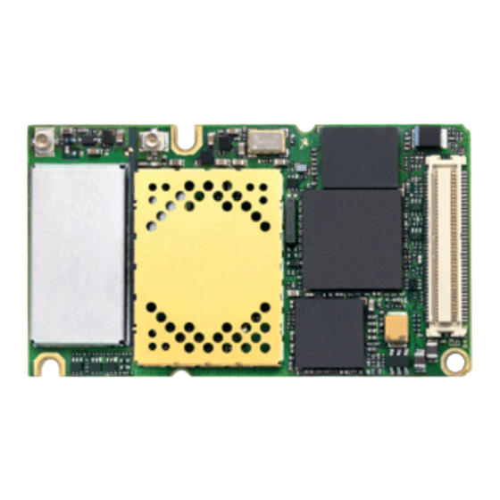
XT65/XT75 Hardware Interface Overview 7 Mechanics Mechanics Mechanical Dimensions of XT65/XT75 Figure 11 shows the top view of XT65/XT75 and provides an overview of the board's mechanical dimensions. For further details see Figure Length: 55.00mm Width: 33.90mm Height: 3.15mm Pin1... -
Page 45: Figure 12: Dimensions Of Xt65/Xt75 (All Dimensions In Mm)
XT65/XT75 Hardware Interface Overview 7.1 Mechanical Dimensions of XT65/XT75 Dimensions of XT65/XT75 (all dimensions in mm) Figure 12: XT65_XT75_HO_v00.130 Page 45 of 67 2006-10-12 Confidential / Preliminary... -
Page 46: Mounting Xt65/Xt75 To The Application Platform
7.2 Mounting XT65/XT75 to the Application Platform Mounting XT65/XT75 to the Application Platform There are many ways to properly install XT65/XT75 in the host device. An efficient approach is to mount the XT65/XT75 PCB to a frame, plate, rack or chassis. -
Page 47: Board-To-Board Application Connector
XT65/XT75 Hardware Interface Overview 7.3 Board-to-Board Application Connector Board-to-Board Application Connector This section provides the specifications of the 80-pin board-to-board connector used to connect XT65/XT75 to the external application. Connector mounted on the XT65/XT75 module: Type: 52991-0808 SlimStack Receptacle 80 pins, 0.50mm pitch, for stacking heights from 3.0 to 4.0mm, Figure 14 for details. -
Page 48: Figure 13: Mating Board-To-Board Connector 53748-0808 On Application
XT65/XT75 Hardware Interface Overview 7.3 Board-to-Board Application Connector Mating connector types for the customer's application offered by Molex: Figure 13: Mating board-to-board connector 53748-0808 on application • 53748-0808 SlimStack Plug, 3mm stacking height, Figure 15 for details. • 53916-0808 SlimStack Plug, 4mm stacking height XT65_XT75_HO_v00.130... -
Page 49: Figure 14: Molex Board-To-Board Connector 52991-0808 On Xt65/Xt75
XT65/XT75 Hardware Interface Overview 7.3 Board-to-Board Application Connector XT65/XT75 Figure 14: Molex board-to-board connector 52991-0808 on XT65_XT75_HO_v00.130 Page 49 of 67 2006-10-12 Confidential / Preliminary... -
Page 50: Figure 15: Mating Board-To-Board Connector 53748-0808 On Application
XT65/XT75 Hardware Interface Overview 7.3 Board-to-Board Application Connector Figure 15: Mating board-to-board connector 53748-0808 on application XT65_XT75_HO_v00.130 Page 50 of 67 2006-10-12 Confidential / Preliminary... -
Page 51: Reference Approval
XT65/XT75 Hardware Interface Overview 8 Reference Approval Reference Approval Reference Equipment for Type Approval The Siemens reference setup submitted to type approve XT65/XT75 consists of the following components: • Siemens XT65/XT75 cellular engine • Development Support Box DSB75 • SIM card reader integrated on DSB75 •... -
Page 52: Compliance With Fcc Rules And Regulations
In this case, the FCC label of the module shall be visible from the outside, or the host device shall bear a second label stating "Contains FCC ID QIP XT65" resp. "Contains FCC ID QIP XT75". -
Page 53: Appendix
XT65/XT75 Hardware Interface Overview 9 Appendix Appendix List of Parts and Accessories Table 20: List of parts and accessories Description Supplier Ordering information XT65 Siemens Standard module (Siemens IMEI) Siemens ordering number: L36880-N8835-A100 Customer IMEI mode: Siemens Ordering number: L36880-N8836-A100... -
Page 54: Table 21: Molex Sales Contacts (Subject To Change)
XT65/XT75 Hardware Interface Overview 9.1 List of Parts and Accessories Table 21: Molex sales contacts (subject to change) Molex Molex Deutschland GmbH American Headquarters For further information please click: Felix-Wankel-Str. 11 Lisle, Illinois 60532 4078 Heilbronn-Biberach U.S.A. http://www.molex.com Germany Phone: +1-800-78MOLEX... -
Page 55: Fasteners And Fixings For Electronic Equipment
XT65/XT75 Hardware Interface Overview 9.2 Fasteners and Fixings for Electronic Equipment Fasteners and Fixings for Electronic Equipment This section provides a list of suppliers and manufacturers offering fasteners and fixings for electronic equipment and PCB mounting. The content of this section is designed to offer basic guidance to various mounting solutions with no warranty on the accuracy and sufficiency of the information supplied. - Page 56 XT65/XT75 Hardware Interface Overview 9.2 Fasteners and Fixings for Electronic Equipment Article number: 07.51.403 Insulating Spacer for M2 Self-gripping Length 3.0mm Material Polyamide 6.6 Surface Black Internal diameter 2.2mm External diameter 4.0mm Flammability rating UL94-HB 2 spacers are delivered with DSB75 Support Board Article number: 05.11.209...
- Page 57 XT65/XT75 Hardware Interface Overview 9.2 Fasteners and Fixings for Electronic Equipment Article number: 01.14.131 Screw M2 DIN 84 - ISO 1207 Length 8.0mm Material Steel 4.8 Surface Zinced A2K Thread Head diameter D = 3.8mm Head height 1.30mm Type Slotted cheese head screw 2 screws are delivered with DSB75 Support Board Article number: 01.14.141...
- Page 58 XT65/XT75 Hardware Interface Overview 9.2 Fasteners and Fixings for Electronic Equipment Article number: 02.10.011 Hexagon Nut DIN 934 - ISO 4032 Material Steel 4.8 Surface Zinced A2K Thread Wrench size / ; Thickness / L 1.6mm Type Nut DIN/UNC, DIN934 2 nuts are delivered with DSB75 Support Board XT65_XT75_HO_v00.130...