Table of Contents
Advertisement
Quick Links
Advertisement
Table of Contents

Related Manuals for Panasonic DVD-LS92P


Summary of Contents for Panasonic DVD-LS92P
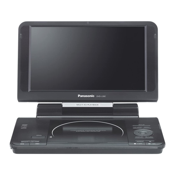
- Page 1 ORDER NO.CHM1102005CE Portable DVD/CD PLAYER DVD-LS92P Model No. DVD-LS92PC RAE1910Z-3C Mechanism Series Colour (K).......Black Type ©Panasonic Corporation 2011. Unauthorized copying and distribution is a violation of law.
-
Page 2: Table Of Contents
TABLE OF CONTENTS PAGE PAGE 1 IMPORTANT SERVICE INFORMATION ---------------------3 12.3. Storing and Handling Test Discs --------------------- 25 1.1. Notes ----------------------------------------------------------3 12.4. Optical adjustment--------------------------------------- 25 1.2. About DivX (only for LS92PC) --------------------------3 13 ABBREVIATIONS ----------------------------------------------- 28 1.3. Manual for Customer --------------------------------------4 14 VOLTAGE CHART ---------------------------------------------- 30 2 SAFETY PRECAUTIONS ----------------------------------------5 14.1. -
Page 3: Important Service Information
1 IMPORTANT SERVICE INFORMATION 1.1. Notes When you replace FLASH ROM or exchange MAIN P.C.B., you have to take “Manual for customer” to the customer with unit (also in the case of unit exchanges.). Please take and use “Manual for customer” from below. 1. -
Page 4: Manual For Customer
1.3. Manual for Customer... -
Page 5: Safety Precautions
2 SAFETY PRECAUTIONS 2.1. GENERAL GUIDELINES 1. When servicing, observe the original lead dress. If a short circuit is found, replace all parts which have been overheated or damaged by the short circuit. 2. After servicing, see to it that all the protective devices such as insulation barriers, insulation papers shields are properly installed. -
Page 6: Precaution Of Laser Diode
4 PRECAUTION OF LASER DIODE... -
Page 7: Specifications
5 SPECIFICATIONS When LCD panel is off while 11 hours (DY-DB20) / 14 hours playing DVD: (DY-DB30) Battery recharge time 7 hours (DY-DB20) / 8 hours (at 20°C) (DY-DB30) Pickup: Operating temperature range: +5 to +35°C (+41 to +95°F) Wave length: 655 nm/790 nm (DVD/CD) Operating humidity range: 5 to 85% RH (no condensation) -
Page 8: How To Replace The Lithium Battery
This model is using a lithium battery for the remote control ass’y. NOTE: The lithium battery is a critical component. ( Type No.: CR2025 Manufactured by Panasonic. ) It must never be subjected to excessive heat or discharge. It must therefore only be fitted in equipment designed specifically for its use. -
Page 9: Service Caution Based On Legal Restrictions
7 SERVICE CAUTION BASED ON LEGAL RESTRICTIONS 7.1. General description about Lead Free Solder (PbF) The lead free solder has been used in the mounting process of all electrical components on the printed circuit boards used for this equipment in considering the globally environmental conservation. The normal solder is the alloy of tin (Sn) and lead (Pb). -
Page 10: Handling Precautions For Traverse Deck
8 HANDLING PRECAUTIONS FOR TRAVERSE DECK The laser diode in the optical pickup may break down due to It has already been adjusted. potential difference caused by static electricity of clothes or human body. So be careful of electrostatic break down during repair of the optical pickup. -
Page 11: Disassembly, Reassembly And Service Position
9 DISASSEMBLY, REASSEMBLY AND SERVICE POSITION... -
Page 12: Disassembly
9.1. Disassembly “Caution to be taken when disassembling and reassembling the unit” • Disconnect the flexible cable from the main P.C.B. before disassembling the monitor assembly. • Do not apply undue force on the flexible cable. There is a danger of breaking the cable. •... -
Page 13: Location
9.2. P.C.B. location Removing battery pack Release the lock lever and remove the battery pack in the direction of the arrow. 1. Remove the 14 screws from the bottom of the unit. 9.3. Main cabinet of the unit 2. Release the latches and remove the bottom cabinet. -
Page 14: Traverse Assembly
9.4. Traverse assembly 9.4.2. Reinstalling traverse assembly 1. Reinstall the traverse assembly to the specified pin of the unit. 2. Reinstall the flexible cable of the optical pickpup unit and lock it securely. 3. Remove the solder of each laser short land of the flexible cable. -
Page 15: Optical Pick-Up Unit
9.5. Optical pick-up unit 9.5.1. Removing optical pick-up unit 9.5.2. Reinstalling optical pick-up unit The optical pick-up unit is factory adjusted. Do not touch the adjustment screw. 1. Reassemble the disassembled parts in the reverse order of disassembly. 2. When reinstalling the traverse assembly on the main unit after installing the optical pick-up unit, make sure to remove the solder from each of the two laser short lands on the flexible cable. -
Page 16: Main P.c.b
9.7. Main P.C.B. 9.9. Monitor assembly 1. Unlock the connector and remove the flexible cable. 2. Remove the connector. 3. Remove the 3 screws and remove the main P.C.B.. 1. Unlock the connector and remove the flexible cable. 2. Remove the 3 screws. 9.8. -
Page 17: Disc Cover
9.11. Monitor cover Caution to be taken when installing monitor assembly 1. Roll the flexible cable as shown figure. 1. Remove Cushion A, B and Monitor Ornament. Avoid the 2. Install the monitor assembly on the cabinet. scratch on the surface of Monitor Cabinet. 2. -
Page 18: Inverter P.c.b
Caution to be taken when installing monitor cover 5. Unlock the connectors and remove the flexible cables. Please do not nip the wire. 9.13. LCD panel 1. Remove the 2 screws. 2. Remove the LCD sheet. 3. Remove the LCD panel into the direction of the arrow. 9.12. -
Page 19: Service Position
9.15. Service position 9.15.1. Board checks 1. Connect the main P.C.B and the traverse assembly with an extension cable. 2. Install the traverse assembly to the tilt adjustment jig using three screws and three washers. Caution: • Remove the rubber cushion from the traverse assembly to prevent it from getting damaged. 3. -
Page 20: Self-Diagnosis Function And Service Mode
10 SELF-DIAGNOSIS FUNCTION AND SERVICE MODE 10.1. Optical Pickup Breakdown Diagnosis As a new feature, this unit has an “optical pick-up problem diagnosis function” and “a tilt adjustment confirmation function” built in. Use the following procedure to efficiently determine the problem and adjust tilt. If "NO DISC" is displayed, before exchanging the optical pick-up, carry out problem diagnosis first. -
Page 21: Dvd Self Diagnostic Function-Error Code
Cautions to be taken when replacing the optical pickup short-circuiting or removing the laser diode. The optical pickup may break down due to the static elec- (Recommended soldering iron) HAKKO ESD Produc tricity of human body. Take proper protection measures 4. -
Page 22: Special Operation Menu
10.4. Special Operation Menu When the power on. Pressing buttons [PLAY],[RETURN] and [TOP MENU] in same time at the unit. Special operation menu will be display. Select menu by cursor button and press [OK] button to activate the commands. -
Page 23: Lens Cleaning
10.5. Lens cleaning When cleaning the lens, use the lens cleaner which product part No. SZZP1038C. -
Page 24: Service Precautions
11 SERVICE PRECAUTIONS 11.1. Firmware version-up of the DVD player • The firmware of the DVD player may be renewed to improve the quality including operation ability and playability to the substan- dard discs.processing to optimize the drive. • Updating firmware 1. -
Page 25: Adjustment Procedures
12 ADJUSTMENT PROCEDURES Caution Be sure to take static electricity countermeasures before adjusting the optical system. Adjust the optical systems according to the prescribed procedure. 12.1. Service Tools and Equipment Application Name Number Tilt adjustment DVD test disc DVDT-S15AS or DVDT-S01 Inspection Extension cable + PCB RFKZ0470 (26Pin) + RFKZ0468(PCB) - Page 26 Remove the solder shorts before trying to make the adjustment. 12.4.1.1. Preparations 1. Connect the main P.C.B. to the traverse ass’y with the extension cable. 2. Install the traverse ass’y to the tilt adjustment jig with three screws and three washers. Caution Remove the rubber cushion of the traverse ass’y.
- Page 27 12.4.1.2. Adjustment 1. Play back the disc (DVDT-S01/S15AS) and make sure the RF signal is outputted. 2. Play back the areas within a radius of 40 ± 1 mm of the disc (middle circumference). 3. Turn the adjustment screw A to minimize the jitter value in the tangential direction. (*Once turn the screw to the full position and then back off.
-
Page 28: Abbreviations
13 ABBREVIATIONS INITIAL/LOGO ABBREVIATIONS INITIAL/LOGO ABBREVIATIONS A0~UP ADDRESS ERROR TORQUE CONTROL ACLK AUDIO CLOCK ERROR TORQUE CONTROL REFER- AD0~UP ADDRESS BUS ENCE ADATA AUDIO PES PACKET DATA ENCSEL ENCODER SELECT ADDRESS LATCH ENABLE ETMCLK EXTERNAL M CLOCK (81MHz/40.5MHz) AMUTE AUDIO MUTE ETSCLK EXTERNAL S CLOCK (54MHz) AREQ... - Page 29 INITIAL/LOGO ABBREVIATIONS INITIAL/LOGO ABBREVIATIONS READ ENABLE VBLANK V BLANKING RFENV RF ENVELOPE COLLECTOR POWER SUPPLY RF PHASE DIFFERENCE OUTPUT VOLTAGE (CD-ROM) REGISTER SELECT VCDCONT VIDEO CD CONTROL (TRACKING RSEL RF POLARITY SELECT BALANCE) RESET DRAIN POWER SUPPLY VOLTAGE RESERVE VIDEO FEED BACK SBI0, 1 SERIAL DATA INPUT VREF...
-
Page 30: Voltage Chart
14 VOLTAGE CHART Note: • Indicated voltage values are the standard values for the unit measured by the DC electronic circuit tester (high-impedance) with the chassis taken as standard. Therefore, there may exist some errors in the voltage values, depending on the internal imped- ance of the DC circuit tester. - Page 31 IC5900 Ref No. IC5950 MODE PLAY STOP IC6001 Ref No. MODE PLAY STOP IC6001 Ref No. MODE PLAY STOP IC6001 Ref No. MODE PLAY STOP IC6001 IC6007 IC6008 Ref No. MODE PLAY STOP IC7500 Q1001 Ref No. MODE 13.9 11.5 PLAY 13.9 11.5...
-
Page 32: Block Diagram
VIDIO DRIVE TRAVERSE MOTOR IC3300 FOCUS COIL IC4200 SPEAKER AUDIO POWER AMP TRACKING DC VOLUME CONTROL HEADPHONE 64Mbit COIL SDRAM IC4005 AUDIO IN/OUT IC6001 OPERATION P.C.B. IC5950,IC5900 IC3201 OPERATION 16Mbit FLASH LED DRIVE REMOTE CONTROL IC3401 RESET DVD-LS92P/PC OVERALL BLOCK DIAGRAM... -
Page 33: Power Supply Block Diagram
PW_SWA +5V CHG-ICTL LBAT Q1604 QR1602 PW_LCD +5V Q1602 VDIF CURRENT CHG-ICTL2 CHARGE CTL QR1603 CADJ PW_CHG+9V Q1004 D1001 CHG-V CHG-V QR1001 OPRON-H OPRON-H PWRNG-L POWER PWRNG-L NG DET ADPON-L ADAPON-L QR1201 SWITCHING DVD2ON-H DVD2ON-H DVD-LS92P/PC POWER SUPPLY BLOCK DIAGRAM... -
Page 34: Servo Block Diagram
Q5281,Q5282 LASER DIODE IC2601-48 LD_CD CD_LD LD DRIVE MD_CD CD_MD M+5.5V APIWM[4]/ALRCLK/DUPRD1/IGPIO[24] SPINDLE MOTOR UNIT INSP SPDRV FIELD/PWMCO[2]/GPIO[51] BEMP POWER LOGIC DETECTER Driver RFINN LIMIT RFINN RFINP RFINP COUT APIWM[5]/ABCLK/DUPTD1/IGPIO[23] 39 STBY/BMSW CTL2 CCOM RNF1 RNF2 DVD-LS92P/PC SERVO BLOCK DIAGRAM... -
Page 35: Audio Block Diagram
QR6005,QR6006 VOLUME VOL_PWM MUTE LOUT- PW_LCD+5V Power Management SHUTDOWN FMTM-LED ROUT+ SPEAKER QR4201,QR4202 JK4012 MUTE AMPMUTE-H MUTE Mode SE/BTL Control KARAPON-H QR4200 HEAD ROUT- BIAS PHONE Depop BYPASS Circuitry QR4001,QR4002 LOUTMUTE-h MUTE Power VOLMAX Clamp HPJIN-L DVD-LS92P/PC AUDIO BLOCK DIAGRAM... -
Page 36: Video Block Diagram
VIDEO DRIVE SOURCE Q7301 DRIVER C_B_U VOD_B DAC1 VIDEO DRIVE JK4001 CVBS_C DAC3 AV IN/OUT IC7500 (SW AMP) PW_LCD+5V +15V[VGH] TFT_VCOM Gen_9 VCOM TFT_STH Gen_5/GPIO[0] TFT_STV Gen_4/VID7 103 GATE TFT_OEH DRIVER Gen_6 TFT_OEV Gen_7 TFT_CKV Gen_8 DVD-LS92P/PC VIDEO BLOCK DIAGRAM... -
Page 37: Schematic Diagram & Schematic Diagram Notes
16 SCHEMATIC DIAGRAM & SCHEMATIC DIAGRAM NOTES 16.1. SCHEMATIC DIAGRAM NOTES This schematic diagram may be modified at any time with the development of new technology. Important safety notice: Components identified by mark have special characteristics important for safety. Furthermore, special parts which have purpose of fire-retardant (resistors), high-quality sound (capacitors), low-noise (resis- tors), etc. -
Page 38: Interconnection Schematic Diagram
CHP1 CHP1 CHP1 DVDD DVDD DVDD DGND DGND DGND AVDD AVDD AVDD AGND AGND AGND SPL+ SPL+ SPL- SPL- SPR+ SPR+ SPR- SPR- SPR+ SPEAKER(R) SPR- PICK-UP UNIT INVERTER P.C.B. FP2501 DGND DGND TRAVERSE MECHANISM UNIT DVD-LS92P/PC INTERCONNECTION SCHEMATIC DIAGRAME... -
Page 39: Charge Battery Section (Main P.c.b. (1/9)) Schematic Diagram
D1456 UNR5213J0L IC1452 MA2J1110GL D1457 R1617 C0DBAGY00001 CHG-ICTL B0JCMD000022 C1457 C1456 C1602 R1612 C1606 C1607 R1614 Q1604 C1454 C1455 6.3V 22 100P B1CFGD000003 QR1603 C1453 R1457 UNR5213J0L 0.01 CHG-ICTL2 DCJIN-H PW_OPR+3.3V OPRON-H PWR-SW ADPNG-L ADPON-L DVD-LS92P/PC CHG-BAT SECTION SCHEMATIC DIAGRAM... -
Page 40: Power Supply Section (Main P.c.b. (2/9)) Schematic Diagram
G1C150M00024 C1008 C1039 CC1101 C1111 330P C1096 R1030 C1009 C1037 1000P 0.022 R1033 C1005 1000P C1002 C1092 C1034 C1035 C1033 R1003 25V 68 0.01 C1010 C1049 R1038 3300P IC1103 C0CBCDC00019 R1032 R1031 PW_CHG+9V C1110 PW_PWR+9V DVD-LS92P/PC POWER SECTION SCHEMATIC DIAGRAM... -
Page 41: Optical Pick Up/Servo Section (Main P.c.b. (3/9)) Schematic Diagram
PVCC22 CKD8 TRV-SW+ PVCC1 VO3F 18 19 TO TRAVERSE MECHANISM UNIT R2606 FP2501 C2659 0.39 1000P K1MN07BA0269 C2656 L2611 G1C220KA0055 L2610 G1C220KA0055 R2697 C2623 C2622 C2621 DGND R2698 100P 100P 100P C2616 C2617 100P 100P DVD-LS92P/PC SER-OPU SECTION SCHEMATIC DIAGRAM... -
Page 42: Schematic Diagram
PAMDQM LDQM PAMWE- PAMDAT15 UDQM PAMCAS- PAMDAT15 CAS# R3301 PAMRAS- RAS# IC3401 C0EBE0000504 PAMCS1- PAMBA PAMADD11 PAMCS0- PAMADD9 CC3401 C3404 PAMADD10 PAMADD8 A10/AP R3401 PAMADD0 PAMADD7 PAMADD1 PAMADD6 PAMADD2 PAMADD5 REAT# PAMADD3 PAMADD4 CB3307 0.01 DVD-LS92P/PC DV5 SECTION SCHEMATIC DIAGRAM(1/2) -
Page 43: Schematic Diagram
1 2 3 4 5 6 7 8 9 10 11 12 13 14 15 16 17 18 19 20 21 22 23 24 25 26 27 28 29 30 31 32 33 34 35 36 37 38 UNR5213J0L DOOR_CLOSED SR CC3077 R3034 C3077 C3007 R3002 6.3V 22 6.3V 22 L3002 J0JHC0000045 DSP_VCC1B C3034 C3008 C3006 6.3V 22 C3005 C3001 C3002 C3003 C3004 0.01 0.01 0.01 0.01 0.01 0.01 DVD-LS92P/PC DV5 SECTION SCHEMATIC DIAGRAM(2/2) -
Page 44: Video Out Section (Main P.c.b. (6/9)) Schematic Diagram
D0GAR00JA028 Q7301 C_B_U B1ABDE000003 C7303 150P R7305 R7306 C7304 100P R7500 +15V[VGH] C7501 C7500 25V 33 IC7500 C0ABBA000001 C7503 R7501 R7502 R7505 4.7K AOUT CC7502 CC7501 C7505 BOUT TFT_VCOM VCOM R7507 C7502 470P R7504 R7503 DVD-LS92P/PC VIDEO SECTION SCHEMATIC DIAGRAME... -
Page 45: Audio Out Section (Main P.c.b. (7/9)) Schematic Diagram
J0JYC0000122 Q4210 SPL- B1GFGCAA0001 LB4013 J0JYC0000122 C4222 R4221 R4226 1000P C4221 R4222 10V 150P SPL+ SPR+ SPR- AMP_5V R4210 AMP_5V CC4200 L4200 D4200 J0JHC0000045 B0ECMR000006 AMP_5V QR4200 PWM_LCD+5V UNR5213J0L C4204 C4205 KARAPON-H C4200 6.3V 220 DVD-LS92P/PC AUDIO SECTION SCHEMATIC DIAGRAME... -
Page 46: Operation Section (Main P.c.b. (8/9)) Schematic Diagram
24 25 26 27 28 29 30 31 32 R6074 R6075 R6071 AMPMUTE-H LOUTMUTE-H +15V-10_EN IRRCV R6006 R6008 R6012 R6014 3.3K 2.2K 1.5K 1.2K D6007 B0JCDD000002 R6052 SIZE BRIGHT F.SKIP R.SKIP S6001 S6002 S6013 S6014 K0F111A00472 K0F111A00472 K0F111A00472 K0F111A00472 DVD-LS92P/PC OPERATION SECTION SCHEMATIC DIAGRAM... -
Page 47: Lcd If Section (Main P.c.b. (9/9)) Schematic Diagram
C0DBZYY00424 R5913 BACKLIGHT_VOL_PWM C5901 R5905 47000P VCC 8 R5907 C5903 0.47 ISEN CDRV 7 L5900 R5906 R5909 C5905 G1C470MA0291 DIM_ENA DRV 6 Q5900 D5901 B0ACCL000003 B1CFMD000012 VSEN GND 5 R5904 C5906 BL_EN C5902 R5903 0.01 5.6K DVD-LS92P/PC LCD_IF SCHEMATIC DIAGRAM... -
Page 48: Operation Section (Operation P.c.b.) Schematic Diagram
3.3K 2.2K 1.5K 1.2K AVSELECT VOL(+) VOL(-) MENU DOWN TOPMENU TL6802 TL6811 S6818 S6817 S6816 S6815 S6805 S6813 S6814 K0F111A00472 K0F111A00472 K0F111A00472 K0F111A00472 K0F111A00472 K0F111A00472 K0F111A00472 TL6807 PLAY S6801 ZA6801 K0F111A00472 K4CZ01000027 1 2 3 DVD-LS92P/PC OPERATION SECTION SCHEMATIC DIAGRAM... -
Page 49: I/Fsection (Inverter P.c.b.) Schematic Diagram
CK9001 AGND AGND AVDD AVDD DGND DGND DVDD DVDD CHP1 CHP1 CHP2 CHP2 CHP3 CHP3 STHR STHR STHL STHL VCOM VCOM VCOM VCOM STVU STVU STVD STVD DGND DGND LED_VCC_L LED_VCC_H CN9004 K1KA02BA0072 LED_VCC_L LED_VCC_H DVD-LS92P/PC I/F SECTION SCHEMATIC DIAGRAM... -
Page 50: Circuit Board Assembly
K5222 CC5220 C5227 K5224 CC6017 C5230 K5223 CC5219 CC5214 R5227 R6074 CC5207 CC6201 CC6016 D6007 K5230 CC6032 CC6203 CC6202 CC6003 FP6202 CC6204 R6018 R6054 IC6008 R6040 CC6206 R4099 CC6014 CC6205 C6011 (COMPONENT SIDE) DVD-LS92P/PC MAIN P.C.B. LS92P: (VEP76254A) LS92PC: (VEP76254B) -
Page 51: Main P.c.b. (2/2) (Foil Side)
K5229 CC5204 R6019 S6002 S6001 R6085 R6097 RX6002 (only for LS92PC) R3012 CC6027 CC3001 CC3002 CC6028 R6099 CC6033 C5250 QR5261 CC6035 R6077 CC6034 S6014 S6013 CC6051 CC6009 CC6010 R6025 D6002 D6003 DVD-LS92P/PC MAIN P.C.B. (FOIL SIDE) LS92P: (VEP76254A) LS92PC: (VEP76254B) -
Page 52: Operation P.c.b
R6804 TL6802 TL6803 TL6811 TL6805 TL6806 TL6807 TL6808 S6805 TL6809 TL6810 R6803 TL6811 RL6801 RL6802 RL6803 S6806 S6804 TL6805 Connector FP6801 ZA6801 R6818 R6802 R6801 R6819 TL6803 RL6801 S6812 S6802 TL6809 TL6808 TL6801 TL6807 R6820 S6803 S6801 DVD-LS92P\PC OPERATION P.C.B.(VEP70272C) -
Page 53: Inverter P.c.b
17.4. INVERTER P.C.B. INVERTER P.C.B. (COMPONENT SIDE) (FOIL SIDE) CK9004 CK9002 CN9001 CK9003 CK9001 CN9004 CN9002 DVD-LS92P/PC INVERTER P.C.B. (VEP76255A) -
Page 54: Exploded View And Replacement Parts List
18 EXPLODED VIEW AND REPLACEMENT PARTS LIST 18.1. Exploded Views and Mechanical Replacement Parts List 18.1.1. Casing Parts & Mechanism Section Exploded View 64 64 64 64 2(RTL) MAIN P.C.B. 1(RTL) OPERATION P.C.B. - Page 55 18.1.2. Mechanism Section Exploded View Grease Screw lock Screw lock Grease Screw lock To DISC MOTOR To MAIN P.C.B. Screw lock To MAIN P.C.B. To TRAVERSE MOTOR ASS'Y Grease Grease Grease Grease Part number Grease RFKXGUD24 Grease JGS0101 Screw lock RZZ0L01...
- Page 56 18.1.3. Packing & Accessories Exploded View A8-1 Battery...
- Page 57 18.1.4. Mechanical Replacement Parts List Safety Ref. Part No. Part Name & Pcs Remarks Description Notes: RMR1704-K LCD OFF BUTTON *Important safety notice: RKS0453B-K BOTTOM CABINET Components identified by mark have special characteris- RMY0378B HEAT SINK PLATE tics important for safety. XQN14+BG3FJK SCREW XQN17+BG6FN SCREW...
-
Page 58: Electrical Replacement Parts List
18.2. Electrical Replacement Parts Safety Ref. Part No. Part Name & Pcs Remarks Description List C1043 F1G1H470A774 50V 47P C1044 F1G1H470A774 50V 47P Notes: C1045 F1G1H470A774 50V 47P *Important safety notice: C1046 F1G1E471A132 25V 470P Components identified by mark have special characteris- C1047 F1G1H221A775 50V 220P tics important for safety. - Page 59 Safety Ref. Part No. Part Name & Pcs Remarks Safety Ref. Part No. Part Name & Pcs Remarks Description Description C3018 F3F0J226A032 6.3V 22U C5806 F1G1C104A127 16V 0.1U C3019 F1G1C103A125 16V 0.01U C5807 F1K1A1060017 10V 10U C3020 F1G1C103A125 16V 0.01U C5808 F1K1C106A062 16V 10U C3021...
- Page 60 Safety Ref. Part No. Part Name & Pcs Remarks Safety Ref. Part No. Part Name & Pcs Remarks Description Description CN9002 K1MN26BA0059 CONNECTOR(26P) JK4011 K2HC104B0044 JACK CN9004 K1KA02BA0072 CONNECTOR(2P) JK4012 K2HC104B0044 JACK D1001 B0BC010A0267 DIODE E.S.D. K1008 ERJ3GEY0R00V 1/10W 0 D1002 B0JCPD000026 DIODE E.S.D.
- Page 61 Safety Ref. Part No. Part Name & Pcs Remarks Safety Ref. Part No. Part Name & Pcs Remarks Description Description LB5805 D0GDR39JA025 1/8W 0.39 R1015 ERJ2RHD103X 1/16W 10K LB5806 J0JHC0000045 COIL R1016 ERJ2RHD202X 1/16W 2K LB5807 D0GAR00JA028 1/32W 0 R1017 ERJ2RHD153X 1/16W 15K LB5808...
- Page 62 Safety Ref. Part No. Part Name & Pcs Remarks Safety Ref. Part No. Part Name & Pcs Remarks Description Description R3012 D0GA102JA028 1/32W 1K R5281 D0GA223JA028 1/32W 22K R3023 D0GA224JA028 1/32W 220K R5282 ERJ3RBD221V 1/16W 220 R3031 D0GA330JA028 1/32W 33 R5283 ERJ2GEJ8R2X 1/16W 8.2...
- Page 63 Safety Ref. Part No. Part Name & Pcs Remarks Safety Ref. Part No. Part Name & Pcs Remarks Description Description R6075 ERJ2GEJ103X 1/16W 10K R6076 ERJ2GEJ103X 1/16W 10K TH6001 ERTJ0EG103FA THERMISTER R6077 ERJ2GEJ103X 1/16W 10K R6078 ERJ2GEJ103X 1/16W 10K X3001 H0J270500080 CRYSTAL OSCILLATOR R6081 ERJ3GEYJ103V 1/10W 10K...
-
Page 64: Schematic Diagram For Printing With A4
19 SCHEMATIC DIAGRAM FOR PRINTING WITH A4...