Table of Contents
Advertisement
Advertisement
Table of Contents

Related Manuals for Bosch DDU S2 Plus


Summary of Contents for Bosch DDU S2 Plus
- Page 1 Display DDU S2 Plus Manual Version 1.0 9/16/2016...
-
Page 2: Table Of Contents
12 Error Memory ..............................113 12.1 General note ....................................113 12.2 Error memory representation in RaceCon ........................113 12.3 Information on errors available from the error memory .................... 115 12.4 Configuration ....................................119 2 / 136 DDU S2 PLUS Manual Bosch Motorsport... - Page 3 16 Fuel Consumption Calculation ........................131 16.1 Setting up fuel consumption calculation and tank mangement ................131 16.2 Fuel consumption diagnosis/counter reset ........................132 16.3 Example ......................................133 17 RaceCon Shortcuts ............................134 Bosch Motorsport DDU S2 PLUS Manual 3 / 136...
-
Page 4: Preparation
Preparation Use the DDU 8 only as intended in this manual. Any maintenance or repair must be performed by authorized and qualified personnel approved by Bosch Motor‐ sport. Operation of the DDU 8 is only certified with the combinations and accessories that are specified in this manual. -
Page 5: Power Supply
Power Supply | 2 Power Supply Bosch Motorsport software is developed for Windows system software. Connect the Ethernet line to your computer and install the driver. Read the manual care‐ fully and follow the application hints step by step. Please ensure that you have a good ground installation. That means: ▪... -
Page 6: Onboard Network Concept
Bosch Motorsport diagnosis connector µC LS_SWITCH1…4 KL31 UBATT_FUSE GND_Starpoint SENSPWR10 Star connection Chassis dig. sensors (e.g. wheelspeed) SENSPWR5 As short as possible active ANA_IN(xy) LS_GND_1 Sensor LS_GND_2 ANA_IN(xx) Sensor Engine_GND SENSGND 6 / 136 DDU S2 PLUS Manual Bosch Motorsport... -
Page 7: Technical Data
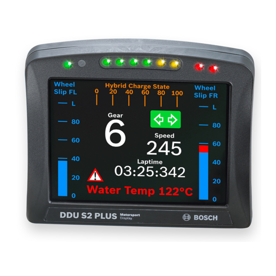
PLUS can be used as stand alone display or in combination with the Bosch ECU family. It can be combined e.g. as copilot display with Bosch DDU 7 or DDU 8. Additional devices can be connected via Ethernet and CAN buses. CAN in and out is freely configurable. - Page 8 External switch for brightness adjust‐ B 261 209 659‐01 ment or page selection, 6 steps Connectors and Wires Motorsport connector 37 pins AS 2‐14‐35PN at DDU S2 PLUS Mating connector F 02U 000 453‐01 AS 6‐14‐35SN Communication CAN interfaces Ethernet 100BaseT...
-
Page 9: Pin Assignment
Ethernet 2 TX + RS232 GPS TX Screen Ethernet ANA_IN_5 Ethernet 1 RX + Ethernet 1 TX + ANA_IN_6 Unused Synchronization CAN1_H CAN1_L RS232 GPS RX Terminal 30 Unused Unused CAN2_H CAN2_L Sensor ground Bosch Motorsport DDU S2 PLUS Manual 9 / 136... -
Page 10: Installation Notes
4 | Technical Data Installation Notes The required software (.pst file) for this device is available in the download area of our homepage www.bosch‐motorsport.com. 10 / 136 DDU S2 PLUS Manual Bosch Motorsport... -
Page 11: Inputs And Outputs
Ethernet switch. The Ethernet port has 'cable auto crossover' functionality. 5.3.3 RS232 ports The DDU 8 has one RS232 serial port. Baud rate for the port is programmable. RS232 port is reserved for GPS receiver. Bosch Motorsport DDU S2 PLUS Manual 11 / 136... - Page 12 5 | Inputs and Outputs 5.3.4 Vehicle diagnoses connector The Bosch Motorsport vehicle diagnosis connector is used as a standard inter‐ face to connect the vehicle to a PC e.g. via a MSA‐Box II. Loom connector: AS 0‐12‐35SN Name Description...
-
Page 13: Mechanical Drawing
Mechanical Drawing | 6 Mechanical Drawing Bosch Motorsport DDU S2 PLUS Manual 13 / 136... -
Page 14: Starting Up
Click 'OK' when done 7.1.2 Starting the unit The DDU 8 powers up by turning on the ignition of the car. At startup the DDU 8 will display a Bosch logo. 14 / 136 DDU S2 PLUS Manual Bosch Motorsport... - Page 15 About RaceCon RaceCon is an all integrated software tool for configuration and calibration of Bosch Motorsport hardware products. It is used to set up, configure and calibrate the DDU 8. For better understanding, Bosch Motorsport offers a video tutorial that explains many functions of RaceCon.
- Page 16 7 | Starting up Main Area Project Toolbox Tree Data Area Properties Message Area 1. Start the RaceCon software. 2. In the ‘File’ menu select ‘New’ to create a new project. 16 / 136 DDU S2 PLUS Manual Bosch Motorsport...
- Page 17 Con project and asks for permission for data download. 6. Click ‘OK’ to proceed. Successful Ethernet connection, DDU 'talks' to PC The download starts and the DDU 8 carries out a reset. Bosch Motorsport DDU S2 PLUS Manual 17 / 136...
-
Page 18: First Display Configuration (Quick Start)
This chapter explains the configuration of a display element showing the battery voltage. See chapter ‘Display element configuration’ for a detailed instruction to config‐ ure display elements. 1. Expand the DDU 8 Project Tree by clicking ‘+’. 18 / 136 DDU S2 PLUS Manual Bosch Motorsport... - Page 19 4. In the DDU 8 Project Tree, click on ‘DDU 8’ to display the available measure‐ ment channels. 5. In the data window, scroll down to ‘ub’ (measurement channel for battery voltage). Bosch Motorsport DDU S2 PLUS Manual 19 / 136...
- Page 20 6. Drag the ‘ub’ measurement channel from the Data Area and drop it on the ‘Large Element’. 7. Right‐click on ‘DDU 8’ in the DDU 8 Project Tree and choose ‘Download Con‐ figuration’. The configurations download starts and the DDU 8 carries out a reset. 20 / 136 DDU S2 PLUS Manual Bosch Motorsport...
- Page 21 Starting up | 7 The value of the battery voltage is displayed on the DDU 8. Bosch Motorsport DDU S2 PLUS Manual 21 / 136...
-
Page 22: Display Configuration
Example: An Alarm placed on ‘All Pages’ is displayed on all display pages and is always in front of other display elements. 8.1.2 Adding a new display page Right‐click on ‘Display’ and click ‘Add Page’ in the menu. 22 / 136 DDU S2 PLUS Manual Bosch Motorsport... -
Page 23: Display Element Configuration
The element and font size can be changed using the Nu‐ meric Wizard. In this view the displayed values are random values and do not Notice show the real values of the measurement channels. Bosch Motorsport DDU S2 PLUS Manual 23 / 136... - Page 24 Drag + Drop The measurement channel is linked to the numeric display element. Configuring a numeric display element 1. Double‐click on the numeric display element. The Numeric Wizard window opens. 24 / 136 DDU S2 PLUS Manual Bosch Motorsport...
- Page 25 Drag the ‘Bargraph’ display element from the Toolbox and drop it on the display page. Drag + Drop Configuring a ‘Bargraph’ display element 1. Double‐click on the ‘Bargraph’ display element. The Bargraph Wizard window opens. Bosch Motorsport DDU S2 PLUS Manual 25 / 136...
- Page 26 Two types of ‘Alarm’ display elements are available: ▪ Alarm: An alarm displaying a defined text ▪ Alarm Icon: An alarm displaying a defined image (e.g. a warning triangle) 26 / 136 DDU S2 PLUS Manual Bosch Motorsport...
- Page 27 Enter the number of decimal places of the measurement channel. g) Choose the font size, alignment, borderstyle, background and foreground color of the 'Alarm' dislay element. 2. Switch to the tab ‘Alarm representation’. Bosch Motorsport DDU S2 PLUS Manual 27 / 136...
- Page 28 Enter the time until the Alarm can appear again after a reset. 3. Click ‘OK’ when done. 4. Copy alarm to all display pages by clicking ‘Move to’ ‐> ‘All Pages’. 28 / 136 DDU S2 PLUS Manual Bosch Motorsport...
- Page 29 2. Switch to the tab ‘Alarm representation’. It is configured in the same way as the ‘Alarm’ text display element. 3. Click ‘OK’ when done. If several active alarms in the display overlap, each alarm is in Notice the foreground for 2 seconds. Bosch Motorsport DDU S2 PLUS Manual 29 / 136...
- Page 30 Choose the font size, alignment, borderstyle, background and foreground color of the Label display element. d) Click the Extended button to show further options to change the color of the title, border and text individually. 2. Click ‘OK’ when done. 30 / 136 DDU S2 PLUS Manual Bosch Motorsport...
- Page 31 Example: The text color changes from white to red when the battery voltage is fewer than 12 V. Conditional formatting is available at numeric, ‘Bargraph’ and ‘Alarm’ display ele‐ ment. Bosch Motorsport DDU S2 PLUS Manual 31 / 136...
-
Page 32: Leds
Manage overlapping elements Delete element LEDs The LEDs are fully configurable to show the optimal shifting point. They can also be configured to flash in case of a customized condition becoming ‘true’. 32 / 136 DDU S2 PLUS Manual Bosch Motorsport... - Page 33 2. Click on the button ‘Add shift lights’. Button 'Add shift lights' Tab 'LEDs' 3. The shift light configuration window appears. Set up the shifting lights using the following configuration possibilities: Bosch Motorsport DDU S2 PLUS Manual 33 / 136...
- Page 34 2nd gear='2' = 50, ...). (ASCII quantization is standard for the 'gear' channel of Bosch ECUs. If you get the gear information of a different control unit as the Bosch ECU (e.g. a gearbox control unit), use the Gear Lookup Table to translate numeric values to ASCII format.
- Page 35 You can create your own LED pattern with an individually created condition. The LEDs flash if the condition becomes true. 1. Click on the button ‘Add pattern’ in the display view. The LED pattern config‐ uration window appears. Bosch Motorsport DDU S2 PLUS Manual 35 / 136...
- Page 36 ‘true’. The 2nd display pattern is only activated if the condition of the 1st display pattern is ‘false’ or the LEDs of the 1st display pattern are transparent. Change the priority by clicking the ‘Move up’ or ‘Move down’ button. 36 / 136 DDU S2 PLUS Manual Bosch Motorsport...
-
Page 37: Page Select
1. Connect 12 position switch to one of analog input ANAxx and sensor GRD. 2. Select one of Analog input and then select Characteristic Curve. 3. Select ”Pull‐up value:” 3.01 kOhm and go Next. Bosch Motorsport DDU S2 PLUS Manual 37 / 136... - Page 38 4. Input the relation between voltage and switch position and go ‘Next’. Voltage = 5000 x R/(R + 3010) 5000: Sensor supply (mV) R: Resister for each Rotary sw position (Ohm) 3010: Pull‐up resistor (Ohm) 38 / 136 DDU S2 PLUS Manual Bosch Motorsport...
- Page 39 5. Input minimum and maximum Limit. Select Output data type from 8, 16 or 32 Bit Do not check Use adjustment value. Input Measurement sheet and go ‘Finish’. 6. Input Name and Description and go Ok. Bosch Motorsport DDU S2 PLUS Manual 39 / 136...
- Page 40 8 | Display Configuration 7. Select Display – Open. 8. Select Setting. 40 / 136 DDU S2 PLUS Manual Bosch Motorsport...
- Page 41 11. Search configured channel and double click and then it shows Raw voltage and Page position. 8.4.2 Option 2: Up/Down switches 1. Connect Up/Down switch to analog input ANAxx and sensor GRD. 2. Select Display Switch and drug into DDU 8. Bosch Motorsport DDU S2 PLUS Manual 41 / 136...
- Page 42 Display switch does not wrap around does not. Input measurement Sheet and go ‘Finish’. 4. Input Name and Description and go ‘Ok’. 42 / 136 DDU S2 PLUS Manual Bosch Motorsport...
- Page 43 Display Configuration | 8 5. Open configured ANA channel and change pull‐up value to 3.01 kOhm and go ‘Finish’. Bosch Motorsport DDU S2 PLUS Manual 43 / 136...
- Page 44 8 | Display Configuration 6. Select Display – Open. 7. Check “Use a channel to switch pages:” and select channel configured above. 44 / 136 DDU S2 PLUS Manual Bosch Motorsport...
- Page 45 Display Configuration | 8 8. Select Download configuration. 9. Open DDU 8 and go Statistics, configured channel position is shown. Bosch Motorsport DDU S2 PLUS Manual 45 / 136...
- Page 46 8 | Display Configuration 8.4.3 Option 3: CAN input signal, math channel or ANA_IN channel 1. Select Display and Setting. 46 / 136 DDU S2 PLUS Manual Bosch Motorsport...
- Page 47 Page 2 is shown with 1.5 <= the value < 2.5 Page 3 is shown with 2.5 <= the value < 3.5 Page 12 is shown with 11.5 <= the value Bosch Motorsport DDU S2 PLUS Manual 47 / 136...
-
Page 48: Display + Led Brightness
8.5.1 Option 1: 6 position switch 1. Connect 6 position switch to one of Analog input ANAxx and Sensor GRD. 2. Select one of Analog input and then select Characteristic Curve. 48 / 136 DDU S2 PLUS Manual Bosch Motorsport... - Page 49 4. Input the relation between voltage and switch position and go Next. Voltage = 5000 x R / (R + 3010) 5000: Sensor supply (mV) R: Resister for each Rotary sw position (Ohm) 3010: Pull‐up resistor (Ohm) Bosch Motorsport DDU S2 PLUS Manual 49 / 136...
- Page 50 5. Input minimum and maximum Limit. Select Output data type from 8, 16 or 32 Bit. Do not check Use adjustment value. Input Measurement sheet and go Finish. 6. Input Name and Description and go Ok. 50 / 136 DDU S2 PLUS Manual Bosch Motorsport...
- Page 51 Display Configuration | 8 7. Select Display – Open. 8. Select Setting. Bosch Motorsport DDU S2 PLUS Manual 51 / 136...
- Page 52 9. Check “Use a channel to switch brightness:” and select channel configured above. Change value for background and LEDs for each switch position if it is nee‐ ded. 10. Select Download configuration. 52 / 136 DDU S2 PLUS Manual Bosch Motorsport...
- Page 53 11. Search configured channel and double click and then it shows Raw voltage and switch position. 8.5.2 Option 2: Up/Down switches 1. Connect Up/Down switch to Analog input ANAxx and Sensor GRD. 2. Select Display Switch and drag into DDU 8. Bosch Motorsport DDU S2 PLUS Manual 53 / 136...
- Page 54 Display switch does not wrap around does not. Input measurement Sheet and go Finish. 4. Input Name and Description and go Ok. 54 / 136 DDU S2 PLUS Manual Bosch Motorsport...
- Page 55 Display Configuration | 8 5. Open configured ANA channel and change pull‐up value to 3.01 kOhm and go Finish. Bosch Motorsport DDU S2 PLUS Manual 55 / 136...
- Page 56 6. Select Display – Open. 7. Check “Use a channel to switch brightness:” and select channel configured above. Change value for Background and LEDs for each switch position if it is nee‐ ded. 56 / 136 DDU S2 PLUS Manual Bosch Motorsport...
- Page 57 Display Configuration | 8 8. Select Download configuration. 9. Open DDU 8 and go Statistics, Configured channel position is shown. Bosch Motorsport DDU S2 PLUS Manual 57 / 136...
- Page 58 8 | Display Configuration 8.5.3 Option 3: CAN input signal, math channel or ANA_IN channel Select Display and Setting. 58 / 136 DDU S2 PLUS Manual Bosch Motorsport...
-
Page 59: Math + Condition Channels
▪ Result can be used as input source for various display elements (numeric ele‐ ments, alarms, Bargraphs) and further calculations in the whole RaceCon project All math channels can be used globally in the whole DDU 8 project. Bosch Motorsport DDU S2 PLUS Manual 59 / 136... - Page 60 Define a value that can be used as a constant in the formula. g) Choose a function. h) Describes the function selected above. 2. Click ‘Finish’ when done. The math channel is displayed in the DDU 8 math channel window. 60 / 136 DDU S2 PLUS Manual Bosch Motorsport...
- Page 61 Enter the Then-condition. Click on the pencil symbol to open an editor to enter expressions. d) Enter the Otherwise-condition.Click on the pencil symbol to open an editor to enter expressions. e) Enter the reset value (must be a number). Click ‘Finish’ when done. Bosch Motorsport DDU S2 PLUS Manual 61 / 136...
- Page 62 Max brake pressure of the variable ‘front p_br_front_mx’ Time Reset Reset Hold Follow value value max. max. is used is used value value Hold max. Threshold Hold max. value reached value 62 / 136 DDU S2 PLUS Manual Bosch Motorsport...
-
Page 63: Condition Channels
▪ Combination of several (up to 16) condition channels for more complex cal‐ culations ▪ Logical results All conditions can be used globally in the whole DDU 8 project. 8.7.1 Creating a new condition channel Follow the steps shown in the screenshot. Bosch Motorsport DDU S2 PLUS Manual 63 / 136... - Page 64 - Pulse: Result is a short one-time pulse if the condition is fulfilled. - Toggling output: Result is a pulse that lasts until the next condition is fulfilled. Click ‘Ok’ when done. The conditional channel is displayed in the condition chan‐ nel window. 64 / 136 DDU S2 PLUS Manual Bosch Motorsport...
- Page 65 ▪ Toggling output: Result is a pulse that lasts until the next condition is fulfil‐ led. Click ‘Finish’ when done. The conditional combination is displayed in the condi‐ tion channel window. Bosch Motorsport DDU S2 PLUS Manual 65 / 136...
-
Page 66: Can Bus
CAN bus in project tree (1 MBaud, 500 kBaud, 250 kBaud, 125 kBaud). Row counter concept ▪ Re‐use (multiplex) of message identifiers ▪ One byte of message contains row counter ▪ 7 bytes payload remaining ▪ Position of row counter is configurable 66 / 136 DDU S2 PLUS Manual Bosch Motorsport... -
Page 67: Can Input
2. Select ‘New CAN Channel’ from menu. 3. Insert name and description of channel. 4. Click ‘OK’ when done. The channel is listed in the Data window and a CAN channel configuration win‐ dow opens. Bosch Motorsport DDU S2 PLUS Manual 67 / 136... - Page 68 Extracting data from CAN bus Representation: Byte Some CAN devices need to be addressed by a byte represented CAN channel. The address can be assigned in this window and is illustrated by a bargraph. 68 / 136 DDU S2 PLUS Manual Bosch Motorsport...
- Page 69 Enter data position, length and format. f) The bargraph shows assignment of the bytes. - Red colored fields show the assignment of the data bytes. - Orange colored fields show the assignment of the multiplexer bytes. Bosch Motorsport DDU S2 PLUS Manual 69 / 136...
- Page 70 Enter minimum physical limit of the channel. (for manual setup) f) Enter maximum physical limit of the channel. (for manual setup) g) Check the box to automatically adjust the limits of the channel. 70 / 136 DDU S2 PLUS Manual Bosch Motorsport...
-
Page 71: Special Features
Measurement Sheet 1 is displayed in Main Area. 2. Click on ‘Measurement elements’ in the Toolbox. 3. Drag the desired Measurement element (e.g. Numeric Indicator) and drop it on the Measurement Sheet. Bosch Motorsport DDU S2 PLUS Manual 71 / 136... - Page 72 9.2.8 Import a CAN database (DBC) file 1. Right‐click on CAN Input of desired bus (CAN1, CAN2 or CAN3). 2. Select ‘Import DBC file’ from menu. A file browser opens. 72 / 136 DDU S2 PLUS Manual Bosch Motorsport...
- Page 73 4. Click ‘OK’ when done. 9.2.10 Import RaceCon CAN configuration 1. Right‐click on CAN Input of desired bus (CAN1, CAN2 or CAN3). 2. Select ‘Import…’ from menu. A file browser opens. Bosch Motorsport DDU S2 PLUS Manual 73 / 136...
- Page 74 6. Click ‘Finish’. If a measurement channel belongs to more than one source (e.g. and MS 5.1), the ‘Solve Label Ambiguity’ window opens. 7. Assign the ambiguous channels to the desired source. 8. Click ‘Finish’. 74 / 136 DDU S2 PLUS Manual Bosch Motorsport...
-
Page 75: Can Output
1. Right‐click on CAN Output of desired bus (CAN1, CAN2 or CAN3). 2. Select ‘New CAN Message’ from menu. The ‘Create new CAN Out message’ window opens. 3. Enter name of message, CAN‐Id and Grid (output interval). 4. Optionally, specify a multiplexer. Bosch Motorsport DDU S2 PLUS Manual 75 / 136... - Page 76 Set up word length, byte order and quantization Set byte order of channel on CAN bus Word length and quantization of channel are fixed. Byte Order can only be changed if a channel allocates more than one byte. 76 / 136 DDU S2 PLUS Manual Bosch Motorsport...
- Page 77 1. Right‐click on ‘CAN Outputs’ of desired bus (CAN1, CAN2 or CAN3). 2. Select ‘Import…’ from menu. A file browser opens. 3. Select the input file and click ‘OK’. An ‘Import Selection’ window opens. 4. Select channels to import. Bosch Motorsport DDU S2 PLUS Manual 77 / 136...
- Page 78 6. Click ‘Finish’. If a measurement channel belongs to more than one source (e.g. and MS 5.1), the ‘Solve Label Ambiguity’ window opens. 7. Assign the ambiguous channels to the desired source. 8. Click ‘Finish’. 78 / 136 DDU S2 PLUS Manual Bosch Motorsport...
-
Page 79: Analog And Frequency Inputs
Filtered channels are routed through digital low pass filters: ▪ DDU 8 uses A/D converter oversampling and digital filtering to recording rate ▪ Digital filters eliminate ‘out‐of‐band’ noise ▪ Cut‐off frequency automatically adjusted to recording rate Bosch Motorsport DDU S2 PLUS Manual 79 / 136... -
Page 80: Configuring Inputs
2. Expand the list of ‘I/O Channels’ by clicking on ‘+’ in the DDU 8 Project Tree. 3. Drag the ‘Bosch Sensor Wizard’ from the Toolbox and drop it on the desired analog input channel in the DDU 8 Project Tree. - Page 81 Available measurements for channel: Measurement label Function raw_name mV value of sensor raw_name_fi Filtered mV value of sensor name Physical value of sensor name_fi Filtered physical value Bosch Motorsport DDU S2 PLUS Manual 81 / 136...
- Page 82 The fixed value of the internal pullup‐resistor is 3,010 Ohm. If using an additional external pullup‐resistor, set up the overall resistance. 5. Click ‘Next’ when done. The second part of the ‘Sensitivity/Offset Wizard’ opens. 82 / 136 DDU S2 PLUS Manual Bosch Motorsport...
- Page 83 ‘Setting up an online measurement 100]’. 7. Click ‘Finish’ when done. 8. Enter channel name and description. 9. Click ‘OK’ when done. The channel is inserted into the DDU 8 Project Tree. Bosch Motorsport DDU S2 PLUS Manual 83 / 136...
- Page 84 2. Expand the list of ‘I/O Channels’ by clicking on ‘+’ in the DDU 8 Project Tree. 3. Drag the ‘Characteristic Curve’ analogue signal source from the Toolbox and drop it on the desired analogue input channel in the DDU 8 Project Tree. 84 / 136 DDU S2 PLUS Manual Bosch Motorsport...
- Page 85 The fixed value of the internal pull up‐resis‐ tor is 3,010 Ohm. If using an additional external pull up‐resistor, set up the overall resistance. 5. Click ‘Next’ when done. The second part of the ‘Sensitivity/Offset Wizard’ opens. Bosch Motorsport DDU S2 PLUS Manual 85 / 136...
- Page 86 The channel is inserted into the DDU 8 Project Tree. Channel is linked to ANA05 Characteristic Adjustment curve for sensor is disabled Input pin Pull-up resistor is activated Available measurements for channel: 86 / 136 DDU S2 PLUS Manual Bosch Motorsport...
- Page 87 2. Expand the list of ‘I/O Channels’ by clicking on ‘+’ in the DDU 8 Project Tree. 3. Drag the ‘Multipoint Adjustment’ analog signal source from the Toolbox and drop it on the desired analog input channel in DDU 8 Project Tree. Drag + Drop Bosch Motorsport DDU S2 PLUS Manual 87 / 136...
- Page 88 Select type of curve Physical Enter physical (channel) adjustment values value her (can still be edited later) Electrical (pin) value 6. Click ‘Next’ when done. The third part of the ‘Multipoint Adjustment Wizard’ opens. 88 / 136 DDU S2 PLUS Manual Bosch Motorsport...
- Page 89 Online definition of the curve is covered in the chapter ‘Online calibration of measurement channels 106]’ of this manual. Bosch Motorsport DDU S2 PLUS Manual 89 / 136...
- Page 90 Recorded signal 100Hz Wert (unfiltered) -0.5 -0.5 -1.5 Abtastwerte (dezimiert) -1.5 100Hz Abtastrate 1000 1500 2000 2500 3000 Abtastwerte (roh) Sensor signal with noise Wert Recorded signal 100Hz (filtered) -0.5 -1.5 Abtastwerte (gefiltert) 90 / 136 DDU S2 PLUS Manual Bosch Motorsport...
- Page 91 3. Drag the ‘Velocity’ digital signal source from the Toolbox and drop it on the desired ‘REV’ input channel in the DDU 8 Project Tree. Drag + Drop The ‘Velocity Wizard’ opens. Bosch Motorsport DDU S2 PLUS Manual 91 / 136...
-
Page 92: Configuring Computed Sources
Measurement of ‘Revolution’ is similar. Notice 10.4 Configuring computed sources Computed sources receive data from a measurement channel rather than an in‐ put pin. ▪ Sensitivity/Offset calculation on input channel 92 / 136 DDU S2 PLUS Manual Bosch Motorsport... - Page 93 Choose input channel Choose unit group and unit of output Enter sensivity and offset of conversion formula 3. Click ‘Next’ when done. The second part of the ‘Computed Sensitivity/Offset Wizard’ opens. Bosch Motorsport DDU S2 PLUS Manual 93 / 136...
-
Page 94: Hysteresis
1. Click ‘Measurement Sources’ in the Toolbox. 2. Drag the ‘Hysteresis’ computed source from the Toolbox and drop it on ‘Computed Channels’ in the DDU 8 Project Tree. A ‘Hysteresis Wizard’ opens. 94 / 136 DDU S2 PLUS Manual Bosch Motorsport... - Page 95 4. Click ‘Finish’ when done. 5. Enter channel name and description. 6. Click ‘OK’ when done. The channel is inserted into the DDU 8 Project Tree. Bosch Motorsport DDU S2 PLUS Manual 95 / 136...
- Page 96 2. Click on ‘Measurement Sources’ in the Toolbox. 3. Drag the ‘Speed’ computed source from the Toolbox and drop it on ‘Compu‐ ted Channels’ in the DDU 8 Project Tree. Do not drop it on ‘DDU 8’! 96 / 136 DDU S2 PLUS Manual Bosch Motorsport...
- Page 97 4. Click ‘Finish’ when done. The speed calculation is inserted into the DDU 8 Project Tree. Speed calculation DDU S2 PLUS Project Tree Measurement channels calculated speed and calculated distance Configuration window Bosch Motorsport DDU S2 PLUS Manual 97 / 136...
-
Page 98: Online Measurement
Yellow dot indicates live connection to the device, but local RaceCon configu- ration does not match DDU S2 PLUS configuration Click 'OK' to download RaceCon configuration to device Status message below 98 / 136 DDU S2 PLUS Manual Bosch Motorsport... - Page 99 11.1.3 Configuration download 1. Right‐click on DDU 8 in the DDU 8 Project Tree. 2. Select ‘Download configuration’. The configuration download starts. A Green dot and background indicate a successful download. Bosch Motorsport DDU S2 PLUS Manual 99 / 136...
-
Page 100: Setting Up An Online Measurement
Back to page ‘System’, from the context menu of the project, new measurement pages can be created. From the context menu of a measurement page, the folder can be renamed and deleted. It also allows the creation of measurement pages. 100 / 136 DDU S2 PLUS Manual Bosch Motorsport... - Page 101 Tabs to switch between sheets To add an element to a measurement sheet, do following steps: 1. Drag a measurement element from the Toolbox and drop it on the measure‐ ment sheet. Bosch Motorsport DDU S2 PLUS Manual 101 / 136...
- Page 102 2. Select the desired measurement channel and drop it on the measurement el‐ ement. If the DDU 8 is online, the value is displayed. Drag + Drop The measurement element’s appearance can be changed from the context menu of the element. 102 / 136 DDU S2 PLUS Manual Bosch Motorsport...
- Page 103 Automatic creation of measurement sheets RaceCon can create measurement sheets automatically. You can create and use measurement sheets with the DDU 8 as well as with all other devices connected to RaceCon. Drag + Drop Bosch Motorsport DDU S2 PLUS Manual 103 / 136...
- Page 104 1. During the configuration of a measurement channel, select a measurement sheet from the list box or enter a name for a new measurement sheet. Select existing sheet from list or enter name of new sheet 104 / 136 DDU S2 PLUS Manual Bosch Motorsport...
- Page 105 2. Switch between different sheets using the tabs at the bottom of the page or the keyboard shortcuts associated with the sheets. 3. Press the ‘Esc’ key to return to ‘Design Mode’. Bosch Motorsport DDU S2 PLUS Manual 105 / 136...
-
Page 106: Online Calibration Of Measurement Channels
▪ Analog sensors drift with age, temperature, etc. ▪ Manual calibration is necessary ▪ Solution: online offset calibration ▪ Example: acceleration sensor 11.3.1 Enable online offset calibration for measurement channel During creation of the measurement channel 106 / 136 DDU S2 PLUS Manual Bosch Motorsport... - Page 107 Data Area. 3. Enter the physical target value (e.g. 1 G) and press the ‘Calibrate’ button. Calibration target value Initiate calibration The sensor’s offset is now calibrated. Bosch Motorsport DDU S2 PLUS Manual 107 / 136...
-
Page 108: Group Adjustment
Working with automatically created measurement sheets is ex‐ Notice plained in chapter ‘Setting up an online measurement 100]’. 4. Click ‘Finish’ when done. 5. Enter channel name and description. 6. Click ‘OK’ when done. 108 / 136 DDU S2 PLUS Manual Bosch Motorsport... - Page 109 1. Connect the input pin to GND using a push‐button. 2. Make sure the pullup‐resistor is enabled, if you selected ‘active low’ trigger polarity. 3. Double‐click on the input channel ‘grp_adj_channel’ of the group adjustment. Bosch Motorsport DDU S2 PLUS Manual 109 / 136...
-
Page 110: Online Calibration Of Multipoint Adjustment Channels
Con, see chapter ‘Connecting the unit to RaceCon’. 3. Click on the desired channel in the DDU 8 Project Tree. 4. Double‐click on a measurement channel in the Data Area to open the online view. 110 / 136 DDU S2 PLUS Manual Bosch Motorsport... - Page 111 (e.g. 745 N). 8. Press the ‘Calibrate’ button of the desired calibration point. 9. Repeat for all curve points. 10. Click ‘Close’ when done. The calibration curve is displayed in the online view. Bosch Motorsport DDU S2 PLUS Manual 111 / 136...
- Page 112 11 | Online Measurement Adjustment points vs. offset adjustment 112 / 136 DDU S2 PLUS Manual Bosch Motorsport...
-
Page 113: Error Memory
12.2 Error memory representation in RaceCon Bosch Motorsport devices feature an error memory. Information on errors can be visualized via RaceCon (online measurement) or can be transmitted via telemetry. 12.2.1 Accessing the memory... - Page 114 The error memory is not cleared by a configuration download and is not cleared by a power cycle. 12.2.2 Clearing the error memory There are two ways of clearing the error memory, both are shown in the follow‐ ing illustration: 114 / 136 DDU S2 PLUS Manual Bosch Motorsport...
-
Page 115: Information On Errors Available From The Error Memory
1: at least one inactive error present in memory, no active errors 2: at least one active error present in memory If displayed in a measurement sheet, this property’s value (0, 1 or 2) is translated into a verbal description: Bosch Motorsport DDU S2 PLUS Manual 115 / 136... - Page 116 MIL off (black) No entries 1 (at least one inactive error present in memory, no active errors) Constantly orange border MIL constantly orange Info cycling through errors present in error memory 116 / 136 DDU S2 PLUS Manual Bosch Motorsport...
- Page 117 (e.g. C 60) and are not error properties (e.g. “error no. 3 from the error memory”). As a consequence, only one property label is available in each device. The errors from the error memory (possibly more Bosch Motorsport DDU S2 PLUS Manual 117 / 136...
- Page 118 (while more than one error is active) and watch the values change periodically: The verbal representation of the numerical codes of these labels can be visual‐ ized in the properties window of the respective label: 118 / 136 DDU S2 PLUS Manual Bosch Motorsport...
-
Page 119: Configuration
ANA pin setup wizard; to allow for a diagnosis re‐ garding shortcut to ground, shortcut to battery voltage, cable breakage, a mini‐ mum / maximum has to be defined. Bosch Motorsport DDU S2 PLUS Manual 119 / 136... - Page 120 Open line detection is triggered as shown in the illustration: 120 / 136 DDU S2 PLUS Manual Bosch Motorsport...
-
Page 121: Firmware
Calibration data: Characteristic curves and offsets created by online calibration at the vehicle. Recorded data: Measurement data recorded during vehicle operation. 13.2 Firmware update The scheme shows the process during each connection between RaceCon and DDU 8. Bosch Motorsport DDU S2 PLUS Manual 121 / 136... - Page 122 3. Click ‘OK’ when done. The firmware update starts. The DDU 8 displays the message ‘Updating firm‐ ware’. Do not switch off the car’s ignition or interrupt the power supply of the DDU 8! 122 / 136 DDU S2 PLUS Manual Bosch Motorsport...
- Page 123 When the firmware update is complete, the DDU 8 displays the message ‘Up‐ dating firmware finished. Do a powercycle.’ Switch the car’s ignition off and on again to cycle the power of the DDU 8. Bosch Motorsport DDU S2 PLUS Manual 123 / 136...
-
Page 124: Clone The Unit
1. Click ‘Clone apply’ in Extras menu. 2. Choose clone file. 3. Click ‘Ok’. Please remember that following properties are not stored into the clone: ▪ Lifetime of device ▪ Serial number ▪ Upgrade features 124 / 136 DDU S2 PLUS Manual Bosch Motorsport... -
Page 125: Gps Sensor
GNSS Receiver. This sensor is based on a U‐Blox 8 chipset and is fully configura‐ ble with the Navilock “U‐Center” software. To use this sensor with Bosch Motor‐ sport components the transfer rate, the satellite system and the update rate need to be reconfigured. - Page 126 RaceCon. For a good signal quality we recommend 115,200 baud. ▪ Click on “Send” to store the new setting in “U‐Center”. ▪ Click on “CFG (Configuration)”. ▪ Click on “Send” to save the new setting on the sensor. 126 / 136 DDU S2 PLUS Manual Bosch Motorsport...
- Page 127 ▪ Click on “Send” to store the new setting in “U‐Center”. ▪ As during configuration step 1, click on “CFG (Configuration)”. ▪ Click on “Send” to save the new setting on the sensor. Bosch Motorsport DDU S2 PLUS Manual 127 / 136...
-
Page 128: Measurement Labels
Position Dilution Of Precision gps_HDOP Horizontal Dilution Of Precision gps_VDOP Vertical Dilution Of Precision gps_lat Latitude +/‐ [degree] gps_long Longitude +/‐ [degree] gps_elv Antenna altitude above/below mean sea level (geoid) in meters 128 / 136 DDU S2 PLUS Manual Bosch Motorsport... -
Page 129: Gps Troubleshooting
2 of the DDU 8? Is the GPS sensor powered up? Does the GPS sensor deliver RS232 signal levels? Is the sensor connected to the „sensor ground“ of the device? Bosch Motorsport DDU S2 PLUS Manual 129 / 136... - Page 130 GPS sensor values are frozen Does the sensor has lost its reception? The old values will be kept if the reception is lost. The gps_smask channel shows which NMEA sentence is received. 130 / 136 DDU S2 PLUS Manual Bosch Motorsport...
-
Page 131: Fuel Consumption Calculation
1. Select ‘Measurement Sources’ in Toolbox. 2. Drag ‘Fuel’ element and drop it on the vehicle in System Overview. Do not drop it on the DDU 8! Drag + Drop A ‘fuel consumption wizard‘ opens. Bosch Motorsport DDU S2 PLUS Manual 131 / 136... -
Page 132: Fuel Consumption Diagnosis/Counter Reset
Double‐click on any ‘fuel_xxx’ channel in channel list. A diagnosis window opens in Main Area. Button to reset total fuel consumption (Reset with RaceCon only) Button to reset fuel consumption manually (Can also be triggered ) Settings overview 132 / 136 DDU S2 PLUS Manual Bosch Motorsport... -
Page 133: Example
Remaining fuel in tank, starting at tank capacity Fuel_fuellap_dls Fuel consumption for current lap, starting at ‘0’ Fuel_fuellapold_dls Fuel consumption of last lap completed Fuel_laprem_dls Remaining laps with fuel in tank Bosch Motorsport DDU S2 PLUS Manual 133 / 136... -
Page 134: Racecon Shortcuts
Delete seleted object Display page, measurement page Cursor Move selected display element one grid unit in chosen direction SHIFT + cursor Enlarge/reduce selected display ele‐ ment one grid unit Switch between display elements 134 / 136 DDU S2 PLUS Manual Bosch Motorsport... - Page 136 Bosch Engineering GmbH Motorsport Robert-Bosch-Allee 1 74232 Abstatt Germany www.bosch-motorsport.com...