Table of Contents
Advertisement
SERVICE MANUAL
Ver 1.0 2002.06
US and foreign patents licensed from Dolby
Laboratories.
CD/MD Player section
Signal-to-noise ratio
95 dB
Frequency response
10 – 20,000 Hz
Wow and flutter
Below measurable limit
Tuner section
FM
Tuning range
FM tuning interval:
50 kHz/200 kHz switchable
87.5 – 108.0 MHz
(at 50 kHz step)
87.5 – 107.9 MHz
(at 200 kHz step)
Aerial terminal
External aerial connector
Intermediate frequency
10.7 MHz/450 kHz
Usable sensitivity
8 dBf
Selectivity
75 dB at 400 kHz
Signal-to-noise ratio
66 dB (stereo),
74 dB (mono)
Harmonic distortion at 1 kHz
0.4 % (stereo),
0.3 % (mono)
Separation
35 dB at 1 kHz/WIDE
Frequency response
30 – 15,000 Hz
Sony Corporation
9-874-054-01
2002F0500-1
e Vehicle Company
C 2002.06
Published by Sony Engineering Corporation
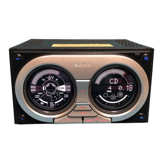
WX-7700MDX
CD
Section
MD
Section
SPECIFICATIONS
AM
Tuning range
AM tuning interval:
9 kHz/10 kHz switchable
531 – 1,602 kHz
(at 9 kHz step)
530 – 1,710 kHz
(at 10 kHz step)
Aerial terminal
External aerial connector
Intermediate frequency
10.7 MHz/450 kHz
30 µV
Sensitivity
Power amplifier section
Outputs
Speaker outputs
(sure seal connectors)
Speaker impedance
4 – 8 ohms
52 W × 4 (at 4 ohms)
Maximum power output
General
Outputs
Audio outputs (front/rear)
Subwoofer output (mono)
Power aerial relay control
terminal
Power amplifier control
terminal
Inputs
Telephone ATT control
terminal
Illumination control
terminal
BUS control input terminal
BUS audio input terminal
AUX IN terminal
Aerial input terminal
MULTI CONTROL AUDIO MASTER
Model Name Using Similar Mechanism
CD Mechanism Type
Optical Pick-up Name
Model Name Using Similar Mechanism
MD Mechanism Type
Optical Pick-up Name
Power requirements
Dimensions
Mounting dimensions
Mass
Supplied accessories
Note
This unit cannot be connected to a digital preamplifier
or an equalizer.
Design and specifications are subject to change
without notice.
E Model
NEW
MG-398D-121
KSS-720A
NEW
MG-164MF-138
KMS-241C
12 V DC car battery
(negative earth)
Approx. 178 × 100 × 194
mm (w/h/d)
Approx. 178 × 100 × 165
mm (w/h/d)
Approx. 3.0 kg
Parts for installation and
connections (1 set)
Card remote commander
RM-X110
Advertisement
Table of Contents

Related Manuals for Sony WX-7700MDX


Summary of Contents for Sony WX-7700MDX
- Page 1 30 – 15,000 Hz terminal Illumination control terminal BUS control input terminal BUS audio input terminal AUX IN terminal Aerial input terminal MULTI CONTROL AUDIO MASTER Sony Corporation 9-874-054-01 2002F0500-1 e Vehicle Company C 2002.06 Published by Sony Engineering Corporation...
- Page 2 LINE WITH MARK 0 ON THE SCHEMATIC DIAGRAMS AND IN THE PARTS LIST ARE CRITICAL TO SAFE OPERATION. REPLACE THESE COMPONENTS WITH SONY PARTS WHOSE PART NUMBERS APPEAR AS SHOWN IN THIS MANUAL OR IN SUPPLEMENTS PUB- LISHED BY SONY.
-
Page 3: Table Of Contents
WX-7700MDX TABLE OF CONTENTS SERVICING NOTES 5-20. Printed Wiring Boards ..........4 – DISPLAY Board (Conductor Side) – ......43 5-21. Schematic Diagram – DISPLAY Board (1/2) – ..... 44 GENERAL 5-22. Schematic Diagram – DISPLAY Board (2/2) – ..... 45 Location of Controls ............ -
Page 4: Servicing Notes
WX-7700MDX SECTION 1 SERVICING NOTES TEST DISC This set can playback a CD-R, CD-RW for audio use. When test this set, use the following test disc. Test disc for CD-R: TCD-R082LMT (Part No.: J-2502-063-1) Test disc for CD-RW: TCD-W082L (Part No.: J-2502-063-2) OPENING AND CLOSING OF FRONT PANEL SECTION IN AN ELECTRIC INTERRUPTION STATE Don't apply impossible power, but open and close slowly with both hands. -
Page 5: General
WX-7700MDX SECTION 2 This section is extracted from instruction manual. GENERAL Location of controls Card remote commander RM-X110 (DISC) (M): OPEN/CLOSE to select upwards SCRL DSPL DISC SHUF (SEEK) (<): (SEEK) (,): to select to select SOURCE – SEEK SEEK... - Page 6 WX-7700MDX Controls of the unit OPEN/ ANGLE CLOSE MODE SOURCE DISC WX-7700MDX The buttons on the unit share the same functions as those on the card remote commander. a ANGLE button * Warning when installing in a car without an ACC (accessory) position on the...
- Page 7 WX-7700MDX Display windows Sound window Operation window ANGLE OPEN/ OPEN/ CLOSE ANGLE CLOSE MODE MODE SOURCE SOURCE DISC AT T AT T DISC Level meter (volume) This manual illustrates the operation window mainly. a DSO e Various items for a setting or a source...
- Page 8 WX-7700MDX To the power aerial control lead or power supply lead of aerial booster amplifier Cautions Notes • This unit is designed for negative earth 12 V • I t is not necessary to connect this lead if there DC operation only.
- Page 9 Japanese cars. In such a case, consult switch kHz) interval, set the switch on the bottom of • Avoid installing the unit in areas subject to your Sony dealer. the unit to the 10 k (200 k) position before OPEN/ dust, dirt, excessive vibration, or high...
-
Page 10: Disassembly
WX-7700MDX SECTION 3 DISASSEMBLY • This set can be disassembled in the order shown below. 3-1. DISASSEMBLY FLOW Note 1: The process can be removed in every turn in the Note 2: Unless finishes all processes in the , it cannot progress to the following process. -
Page 11: Front Panel Section
WX-7700MDX Note: Follow the disassembly procedure in the numerical order given. 3-2. FRONT PANEL SECTION 1 tapping screw 3 guide panel (L) 2 two screws (PTT2.6 × 6) 4 roller (guide) 6 ornamental screw 7 sleeve 3 guide panel (R) -
Page 12: Chassis (T) Section
WX-7700MDX 3-4. CHASSIS (T) SECTION 1 flexible flat cable (40P) 2 connector (CN400) (CN403) 3 two screws (PTT2.6 × 6) 4 chassis (T) section 3 two screws (PTT2.6 × 6) 3-5. MD MECHANISM DECK (MG-164MF-138) 1 two screws (PTT2.6 × 5) 1 two screws (PTT2.6 ×... -
Page 13: Power Board, Chassis (T) Assy
WX-7700MDX 3-6. POWER BOARD, CHASSIS (T) ASSY 1 two screws (PTT2.6 × 6) 2 four ground point screws 3 power board 4 chassis (T) assembly 3-7. HEAT SINK 1 four screws 2 heat sink (PTT2.6 × 10) power board... -
Page 14: Servo (Md) Board
WX-7700MDX 3-8. SERVO (MD) BOARD 1 MD flexible board (CN101) 2 two screws (BVTT2 × 4) 2 two screws (BVTT2 × 4) 3 servo (MD) board 1 sensor connection flexible board (CN103) 1 flexible board (CN103) 1 four screws 3-9. -
Page 15: Float Block
WX-7700MDX 3-10. FLOAT BLOCK 3 Pushing an arrow A part, raise the float block up ward at the front to release a lock. float block 1 tension spring (float B) 5 two damper assies 6 float block 5 two damper assies... -
Page 16: Lever Assy (Le)
WX-7700MDX 3-12. LEVER ASSY (LE) 3 lever (LE) ass’y 2 stopper washer 4 roller (gear E) 3-13. HOLDER ASSY 8 Remove the holder ass’y in the direction of the arrow. 7 type-E stopring 1.5 4 spring (CHKG) 7 type-E stopring 1.5 5 type-E stopring 1.5... -
Page 17: Chucking Arm Assy
WX-7700MDX 3-14. CHUCKING ARM ASSY 1 Remove the chucking arm ass’y in the direction of the arrow. holder ass’y 3-15. OPTICAL PICK-UP (KMS-241C) 4 screw (B2 × 3) 6 bearing (SL) 7 optical pick-up 5 feed screw ass’y (KMS-241C) 3 screw (K2 ×... -
Page 18: Sl Motor Assy (Sled) (M902)/Sp Motor Assy (Spindle) (M901)
WX-7700MDX 3-16. SL MOTOR ASSY (SLED) (M902)/SP MOTOR ASSY (SPINDLE) (M901) 5 screw (P1.7 × 1.8) 0 two screws (P1.7 × 1.8) 6 bracket (SL) 3 screw (PS2 × 8) 7 SL motor ass’y (sled) (M902) 2 screw (PS2 × 4) -
Page 19: Motor Assy (Front Panel Open/Close) (M640)
WX-7700MDX 3-18. MOTOR ASSY (FRONT PANEL OPEN/CLOSE) (M640) 8 motor assy (front panel open/close) 4 two screws (M640) (PTT2.6 × 6) 1 connector 5 Remove the bracket (motor) assy (CN640) in the direction of arrow. 2 ground point screw 3 heat sink 7 two screws (P2 ×... -
Page 20: Bracket (Main)
WX-7700MDX 3-20. BRACKET (MAIN) 1 four screws (PTT2.6 × 6) 4 bracket (main) 2 Remove a solder of bracket (main). 3 Bend three claws. main board 3-21. CHASSIS (T388) ASSY 2 two screws (PTT2 × 3) 3 two screws (PTT2 × 3) -
Page 21: Sensor (Cd) Board
WX-7700MDX 3-22. SENSOR (CD) BOARD 3 guide (disc M) 4 special screw 5 sensor (CD) board 1 two claws 3-23. SERVO BOARD, LO MOTOR SUB ASSY (LOADING) (M103) 2 Remove two solders of lead wire of loading motor. 3 three screws (PS2 ×... -
Page 22: Arm Roller Assy, Load Board
WX-7700MDX 3-24. ARM ROLLER ASSY, LOAD BOARD arm (roller) shaft retainer (roller) 4 shaft retainer shaft retainer (roller) 3 retaining ring (roller) arm (roller) retaining ring (RA) washer (RA) washer 7 special screw 5 arm roller assy 8 load board... -
Page 23: Optical Pick-Up (Kss-720A), Sled Motor Assy (M101)
WX-7700MDX SECTION 4 PHASE ALIGNMENT 3-26. OPTICAL PICK-UP (KSS-720A), SLED MOTOR ASSY (M101) Note: Follow the assembly procedure in the numerical order given. 4-1. ASSEMBLY OF ARM (L/R) ASSY 5 two screws (PS2 × 3) 1 two screws (PS2 × 3) -
Page 24: Diagrams
WX-7700MDX SECTION 5 DIAGRAMS 5-1. BLOCK DIAGRAM – CD SERVO Section – • SIGNAL PATH : CD PLAY DETECTOR CD-DATA, CD-BCK, CD-LRCK CD-DATA AGCO 76 AGCI 74 RFI 72 ASY DOUT (Page 26) CD-BCK SCKO CD-LRCK LRCK BFOT RF AMP,... -
Page 25: Block Diagram - Md Servo Section
WX-7700MDX 5-2. BLOCK DIAGRAM – MD SERVO Section – • SIGNAL PATH DIGITAL SIGNAL PROCESSOR, EFM/ACIRC ENCODER/DECODER, : MD PLAY SHOCK PROOF MEMORY CONTROLLER, ATRAC ENCODER/DECODER EFMO ADDT IC301 (1/2) DATAI SAMPLING FILI RATE XBCKI CONVERTER CLTV LRCKI FILO DIN0... -
Page 26: Block Diagram - Main Section
WX-7700MDX 5-3. BLOCK DIAGRAM – MAIN Section – B+ SWITCH DSP +3.3V Q501 (FOR DIGITAL) CD/MD SELECTOR ELECTRICAL VOLUME CD-DATA, (Page 27) IC504 IC300 (2/2) CD-BCK, R-CH DIGITAL SIGNAL PROCESSOR, CD-LRCK PNJ1 (2/2) CD-DATA DIGITAL FILTER, XMST D/A CONVERTER FL-OUT... -
Page 27: Block Diagram - Display/Bus Control Section
LIQUID CRYSTAL PWM R LCD-INH BATT B+ DISPLAY XTAL LCD741 X701 18.432MHz TH630 C740, R742 D639 CN630 BUS CONTROL IN (FOR SONY BUS) SONY BUS INTERFACE SCHMITT IC630 BATT TRIGGER IC712 D713 RESET RESET RESET SWITCH D636 MD DATA FP DATA... -
Page 28: Block Diagram - Power Supply Section
WX-7700MDX 5-5. BLOCK DIAGRAM – POWER SUPPLY Section – CNP400 (2/2) (POWER) D412 DIMMER DETECT ILLIN ILLIN 95 SWITCH Q308 D820, Q820 ACCIN MD DISC IN DETECT SENSOR TUNER ACCIN ACCESSORY CHECK BACK UP +5V Q304 PACK-IN 116 D820 TH401 D414 TUNER +8.5V... -
Page 29: Note For Printed Wiring Boards And Schematic Diagrams
WX-7700MDX 5-6. NOTE FOR PRINTED WIRING BOARDS AND SCHEMATIC DIAGRAMS • Circuit Boards Location Note on Schematic Diagram: Note on Printed Wiring Boards: • All capacitors are in µF unless otherwise noted. pF: µµF • X : parts extracted from the component side. -
Page 30: Printed Wiring Boards - Cd Section (1/2)
WX-7700MDX 5-7. PRINTED WIRING BOARDS – CD Section (1/2) – • See page 29 for Circuit Boards Location. PICK-UP FLEXIBLE BOARD SERVO (CD) BOARD OPTICAL (COMPONENT SIDE) PICK-UP MAIN BOARD BLOCK (Page 37) CNP370 (KSS-720A) LOAD BOARD (DISC SET) DISC IN... - Page 31 WX-7700MDX 5-8. PRINTED WIRING BOARD – CD Section (2/2) – • See page 29 for Circuit Boards Location. SERVO (CD) BOARD (CONDUCTOR SIDE) 1-682-831- (11)
-
Page 32: Schematic Diagram - Cd Section
WX-7700MDX 5-9. SCHEMATIC DIAGRAM – CD Section – • • See page 52 for Waveforms. See page 55 for IC Block Diagram. (Page 38) The components identified by mark 0 or dotted line with mark 0 are critical for safety. -
Page 33: Printed Wiring Boards - Md Section
WX-7700MDX 5-10. PRINTED WIRING BOARDS – MD Section – • See page 29 for Circuit Boards Location. SERVO (MD) BOARD (COMPONENT SIDE) SERVO (MD) BOARD (CONDUCTOR SIDE) OPTICAL C339 C314 PICK-UP BLOCK (KMS-241C) C309 R331 C317 IC301 R351 CN102 R314... -
Page 34: Schematic Diagram - Md Section (1/2)
WX-7700MDX 5-11. SCHEMATIC DIAGRAM – MD Section (1/2) – • See page 52 for Waveforms. • See page 55 for IC Block Diagrams. (Page 35) The components identified by mark 0 or dotted line with mark 0 are critical for safety. -
Page 35: Schematic Diagram - Md Section (2/2)
WX-7700MDX 5-12. SCHEMATIC DIAGRAM – MD Section (2/2) – • See page 52 for Waveform. • See page 55 for IC Block Diagram. (Page (Page 34) -
Page 36: Printed Wiring Boards - Main Board (Component Side)
WX-7700MDX 5-13. PRINTED WIRING BOARDS – MAIN Board (Component Side) – • :Uses unleaded solder. See page 29 for Circuit Boards Location. • Semiconductor Location Ref. No. Location Ref. No. Location D101 IC500 D102 IC503 POWER BOARD (Page 51) IC504... -
Page 37: Printed Wiring Board - Main Board (Conductor Side)
PNJ1 AUDIO OUT 6 5 4 CN630 PNJ2 BUS AUDIO Ref. No. Location BUS CONTROL IN AUX IN REAR FRONT (FOR SONY BUS) 3 2 1 F-12 MAIN BOARD D680 K-11 (CONDUCTOR SIDE) (FRONT VIEW) IC101 G-10 IC103 IC202 E-10... -
Page 38: Schematic Diagram - Main Board (1/4)
WX-7700MDX 5-15. SCHEMATIC DIAGRAM – MAIN Board (1/4) – • • See page 52 for Waveforms. See page 55 for IC Block Diagrams. (Page 32) C334 C335 100p IC504 C336 CNP370 TC74VHC157 CD/MD 100p SELECTOR CD_LRCK XS24 A_GND LRCK FB507... -
Page 39: Schematic Diagram - Main Board (2/4)
WX-7700MDX 5-16. SCHEMATIC DIAGRAM – MAIN Board (2/4) – • • See page 52 for Waveforms. See page 55 for IC Block Diagrams. C128 R133 C320 R148 C114 R117 R116 Q104 2SD1328 PNJ1 R134 MUTING C129 C145 100p 0.01 CENTER... -
Page 40: Schematic Diagram - Main Board (3/4)
WX-7700MDX 5-17. SCHEMATIC DIAGRAM – MAIN Board (3/4) – • See page 52 for Waveforms. (Page 38) R552 100k L550 R572 2.2k 10µH R573 2.2k C550 1000p R549 R574 R571 100k R554 2.2k C568 D672 0.01 MAZL068D R575 VOLATT DIVER... -
Page 41: Schematic Diagram - Main Board (4/4)
BUSON DATA FRONT PANEL DATA IN IC551 C570 BU_IN D637 MA111 DATA BUS CONTROL IN VIEW ANGLE SENSOR VREF XC61AN4102 BU_IN (FOR SONY BUS) IC553 UNICKO EW-410 CLK IN IC552 D639 BUSON D631 MA8062-M R633 BATT BATT RN5VD33AA MA152WA BUS ON... -
Page 42: Display Board (Component Side)
WX-7700MDX 5-19. PRINTED WIRING BOARD – DISPLAY Board (Component Side) – • :Uses unleaded solder. See page 29 for Circuit Boards Location. • Semiconductor Location Ref. No. Location D714 D801 D802 DISPLAY BOARD (COMPONENT SIDE) LED749 − 758 D803 LED749 LED750 LED749 –... -
Page 43: Printed Wiring Boards - Display Board (Conductor Side)
WX-7700MDX 5-20. PRINTED WIRING BOARDS – DISPLAY Board (Conductor Side) – • :Uses unleaded solder. See page 29 for Circuit Boards Location. MAIN BOARD (Page 36) KEY CONNECT • Semiconductor CN670 FLEXIBLE BOARD Location DISPLAY BOARD (CONDUCTOR SIDE) Ref. No. -
Page 44: Schematic Diagram - Display Board (1/2)
WX-7700MDX 5-21. SCHEMATIC DIAGRAM – DISPLAY Board (1/2) – • • See page 52 for Waveforms. See page 55 for IC Block Diagram. SEG14 COM1 COM2 SEG11 SEG13 COM2 COM3 SEG42 SEG12 COM3 COM4 SEG43 SEG17 COM4 COM5 SEG20 D781... -
Page 45: Schematic Diagram - Display Board (2/2)
WX-7700MDX 5-22. SCHEMATIC DIAGRAM – DISPLAY Board (2/2) – • • See page 52 for Waveform. See page 55 for IC Block Diagram. CN711 LED749-758 (LCD BACK LIGHT) ILL_GND P_ON LED758 LED757 LED756 LED755 LED754 HL002-F01 HL002-F01 HL002-F01 HL002-F01 HL002-F01... -
Page 46: Key Board (Component Side)
WX-7700MDX 5-23. PRINTED WIRING BOARD – KEY Board (Component Side) – • See page 29 for Circuit Boards Location. :Uses unleaded solder. KEY BOARD (COMPONENT SIDE) R778 R779 ANGLE OPEN/CLOSE LSW813 (14) 1-682-243-... -
Page 47: Key Board (Conductor Side)
WX-7700MDX 5-24. PRINTED WIRING BOARD – KEY Board (Conductor Side) – • See page 29 for Circuit Boards Location. :Uses unleaded solder. KEY BOARD (CONDUCTOR SIDE) DISPLAY BOARD CN711 (Page 43) TB802 TB801 (CHASSIS) (CHASSIS) 1-682-243- (14) -
Page 48: Schematic Diagram - Key Board
WX-7700MDX 5-25. SCHEMATIC DIAGRAM – KEY Board – CN800 ILL_GND P_ON ILL_ON D804 MA111 KEY0 KEY01 R801 R802 R803 R804 BU_GND LSW804(1/2) (Page 45) LSW813(1/2) LSW803(1/2) LSW805(1/2) ANGLE OPEN/ R830 CLOSE D805 MA111 R866 R867 R855 R856 R778 R779 R821... -
Page 49: Schematic Diagram - Sub/Power Boards
WX-7700MDX 5-26. SCHEMATIC DIAGRAM – SUB/POWER Boards – • • See page 52 for Waveform. See page 55 for IC Block Diagram. CNP400 C430 REAR LCH(-) C403 R453 FRONT LCH(-) R452 1.2k REAR LCH(+) C459 FRONT LCH(+) POWER AMP REAR RCH(+) -
Page 50: Printed Wiring Board
WX-7700MDX 5-27. PRINTED WIRING BOARD – POWER Board (Component Side) – • See page 29 for Circuit Boards Location. :Uses unleaded solder. • Semiconductor Location Ref. No. Location D400 POWER BOARD D401 (COMPONENT SIDE) D402 D403 D404 D405 D406 K-10... -
Page 51: Printed Wiring Boards - Power Board (Conductor Side)/Sub Board
WX-7700MDX 5-28. PRINTED WIRING BOARDS – POWER Board (Conductor Side)/SUB Board – • See page 29 for Circuit Boards Location. :Uses unleaded solder. • Semiconductor GRN/BLK CNP400 REAR LCH (–) WHT/BLK Location FRONT LCH (–) REAR LCH (+) FRONT LCH (+) Ref. - Page 52 WX-7700MDX • Waveforms – SERVO (CD) Board – – MAIN Board – 1 IC1 wf (XTAL) (CD Play Mode) 6 IC1 oa (FEO) (CD Play Mode) 4 IC303 es (CAPA–) (MD Play Mode) 1 IC500 r; (XTLO38) 6 IC302 1 (BOOST) qa IC550 od (X1) Approx.
- Page 53 WX-7700MDX – DISPLAY Board – 1 IC741 oh (OSC) 3 Q450 (Drain) 2.5 Vp-p 15.6 Vp-p 22.7 µs 3.9 µs 2 IC740 oh (OSC) 4 IC400 1 (CT), IC401 1 (CT) 0.7 mVp-p 2.5 Vp-p 22.7 µs 4.1 µs 3 IC710 ig (XTAL)
- Page 54 WX-7700MDX 8 Q408 (Base) 1.1 Vp-p 3.9 µs 9 IC408 (Collector) 14.8 Vp-p 3.9 µs q; IC401 7 (OUT1) 12.8 Vp-p 3.9 µs qa Q401 q; (OUT2) 13.2 Vp-p 3.9 µs...
-
Page 55: Ic Block Diagrams
WX-7700MDX • IC Block Diagrams – SERVO (CD) Board – IC1 µPD63711GC-8EU 56 55 54 53 52 MICROCOMPUTER 50 C2D3 INTERFACE COMPARATOR C2D2 CD-TEXT AGCI DECODER FEOFS TEOFS C2D1 D/A CONVERTER SUBCODE PROCESSOR C1D2 MEMORY PROCESSOR SRAM AUTO GAIN FD/TD/SD/MD... - Page 56 WX-7700MDX IC2 BA5810FP-E2 CH1 – CH4 POWVCC34 MUTE (CH3, CH4) – – LEVEL – SHIFT – LEVEL SHIFT LEVEL SHIFT – LEVEL – – SHIFT – LOADING PRE FWD REV PREVCC POWVCC12 POWER (PRE, LOADING) (CH1, CH2) SAVE...
- Page 57 WX-7700MDX – SERVO (MD) Board – IC301 CXD2662R 100 99 98 97 96 95 94 93 92 91 90 89 88 87 86 85 84 83 82 81 80 79 78 77 76 SPINDLE GENERATOR SERVO 75 TE MNT0 74 SE...
- Page 58 WX-7700MDX IC302 CXA2523AR 43 42 USROP – RF AGC – USRC RFA1 BPF3T RFA2 RFA3 PEAK3T – HLPT –1 – – –2 – OFST PTGR TEMP PEAK – –2 – BOTTOM 36 BOTM – –1 GRVA PBSW 35 ABCD 34 FE –...
- Page 59 WX-7700MDX IC303 BH6518FS-E2 INTERFACE INTERFACE CHARGE PREDRIVE PREDRIVE PUMP. PREDRIVE PREDRIVE INTERFACE INTERFACE IC305 BA6287F IC306 W194-70G-T2 OUT1 FBIN ÷N PHASE CHARGE DETECTOR PUMP OUT2 LOOP FILTER DRIVER DRIVER OUTPUT 8 CLK2 BUFFER VREF 7 VCC CONTROL LOGIC OUTPUT ÷2...
- Page 60 WX-7700MDX – MAIN Board – IC300 TDA7402TR 33 32 31 24 23 MIXER MONO- MONO- MONO- MONO- MONO- MONO- FADER FADER FADER FADER FADER FADER ACINLF FRONT SUBWOOFER SWINR ACIN +PHASE OUTPUT SWINL REAR CONTROL SELECTOR ACOUTR MAIN ACOUTL SECOND...
- Page 61 WX-7700MDX IC500 CXD2727Q 80 79 78 77 76 75 74 73 72 71 70 69 68 67 66 65 64 63 62 61 60 59 58 54 53 52 AVS6 AVD2 SERIAL SERIAL DATA DATA AVS2 RREF ADC2 AVS8 AVD8...
- Page 62 WX-7700MDX – DISPLAY Board – IC780 RRX9000-0601#1 L IN GND A V IN V AGC VCO NC 11 10 INPUT 320kHz NOISE 320kHz PULSE SLAGE /500kHz SUPPRESSION COUNTER PULSE FORMER BANDGAP REFERENCE L IN GND V STBY IC791 TC7WH123FU (TE12R)
-
Page 63: Ic Pin Function Description
WX-7700MDX 5-29. IC PIN FUNCTION DESCRIPTION • SERVO (MD) BOARD IC301 CXD2662R (DIGITAL SIGNAL PROCESSOR, DIGITAL SERVO SIGNAL PROCESSOR, EFM/ACIRC ENCODER/DECODER, SHOCK PROOF MEMORY CONTROLLER, ATRAC ENCODER/DECODER) Pin No. Pin Name Description Focus OK signal output to the MD mechanism controller MNT0 (FOK) “H”... - Page 64 WX-7700MDX Pin No. Pin Name Description XRAS Row address strobe signal output to the D-RAM “L” active Write enable signal output to the D-RAM “L” active Two-way data bus with the D-RAM (IC307) MVCI Digital in PLL oscillation input from the external VCO Not used...
- Page 65 WX-7700MDX Pin No. Pin Name Description SRDR Sled servo drive PWM signal (–) output to the BH6518FS SFDR Sled servo drive PWM signal (+) output to the BH6518FS SPRD Spindle servo drive PWM signal (–) output to the BH6518FS SPFD...
- Page 66 WX-7700MDX • SERVO (MD) BOARD IC302 CXA2523AR (RF AMP, FOCUS/TRACKING ERROR AMP) Pin No. Pin Name Description I-V converted RF signal I input from the optical pick-up block detector I-V converted RF signal J input from the optical pick-up block detector Middle point voltage (+1.65V) generation output terminal...
- Page 67 WX-7700MDX • SERVO (MD) BOARD IC501 CXP84340-225Q (MD MECHANISM CONTROLLER) Pin No. Pin Name Description 1 to 5 TIN3 to TIN7 Input of the 4x8 matrix test keys (“L” is always output, except in test mode) Not used MD loading motor control signal (loading direction) output to the MD mechanism deck section LOAD motor driver “H”...
- Page 68 Two way data bus with the external EEPROM device Not used MD-SO Writing serial data signal output to the CXD2662R and CXA2523AR Unilink on/off control signal output for the SONY bus interface “L”: link on, “H”: link off LINKOFF Not used UNIREQ Data request signal output terminal (for SONY bus) “H”: request on Not used...
- Page 69 WX-7700MDX • MAIN BOARD IC500 CXD2727Q (DIGITAL SIGNAL PROCESSOR, DIGITAL FILTER, D/A CONVERTER) Pin No. Pin Name Description VSS1 — Ground terminal (digital system) 2 to 15 Input terminal for the test (fixed at “L”) 16 to 21 TST0 to TST5 Input terminal for the test (fixed at “L”)
- Page 70 WX-7700MDX Pin No. Pin Name Description Serial data transfer clock signal input from the master controller for the micro controller interface Transfer enable signal output for micro controller interface to the master controller REDY “L”: transfer prohibition TRDT Serial data output to the master controller and liquid crystal display controller...
- Page 71 DSPRST System reset signal output to the CXD2727Q “L”: reset Audio line muting on/off control signal output “H”: muting on System reset signal output to the MD mechanism controller, SONY bus interface IC and display SYSRST controller “L”: reset CD/MD selection signal output to the CD/MD selector “L”: CD, “H”: MD...
- Page 72 WX-7700MDX Pin No. Pin Name Description — Ground terminal — Connected to coupling capacitor for the power supply CD XRST System reset signal output to the uPD63711GC “L”: reset Command/parameter recognition selection signal output to the uPD63711GC CD A0 “L”: command transmission, “H”: parameter transmission...
- Page 73 Power on/off signal input of the MD mechanism deck section from the MD mechanism controller MD ON “H”: power on Back-up power supply detect signal input from the SONY bus interface IC BU IN “L” is input at low voltage...
- Page 74 WX-7700MDX Pin No. Pin Name Description Power wake up control signal output terminal for sleep release of the master controller WAKEUP “H”: active 107 to 111 Not used Frequency select switch input terminal 9K/10K “L”: AM 10k step/FM 200k step, “H”: AM 9k step/FM 50k step...
- Page 75 WX-7700MDX • MAIN BOARD IC660 RRX9000-0401R#01 (SIRCS CONTROLLER) Pin No. Pin Name Description — Power supply terminal (+3.3V) — Ground terminal System clock input terminal (4 MHz) XOUT System clock output terminal (4 MHz) CNVSS — Ground terminal RESET Reset signal input from the master controller “L”: reset...
- Page 76 45 to 49 Not used LINKOFF Uni link on/off control signal output for the SONY bus interface “L”: link on, “H”: link off Not used ILLON Power supply on/off control signal output of the front panel illumination LED “H”: power on —...
- Page 77 Ground terminal Not used — Power supply terminal (+5V) 90 to 96 Not used UNISO Serial data output to the SONY bus interface IC UNISI Serial data input from the SONY bus interface IC 99, 100 — Ground terminal UNICKI...
-
Page 78: Exploded Views
WX-7700MDX SECTION 6 EXPLODED VIEWS NOTE: • -XX and -X mean standardized parts, so they • Items marked “*” are not stocked since they The components identified by mark 0 or dotted line with mark may have some difference from the original are seldom required for routine service. -
Page 79: Sub Panel Sub Assy Section
WX-7700MDX 6-2. SUB PANEL SUB ASSY SECTION not supplied Ref. No. Part No. Description Remark Ref. No. Part No. Description Remark X-3380-866-2 PANEL SUB ASSY, SUB A-3274-514-A SUB BOARD, COMPLETE * 52 X-3377-968-1 ESCUTCHEON (MD) ASSY * 56 3-230-714-01 SHEET (PHOTO) 3-025-484-01 SPRING (DOOR) 3-233-356-01 BUTTON (EJECT) (Z MD. -
Page 80: Front Panel Section
WX-7700MDX 6-3. FRONT PANEL SECTION display board section front panel sub section Ref. No. Part No. Description Remark Ref. No. Part No. Description Remark * 101 X-3377-682-1 BRACKET (L) ASSY 1-823-602-21 CABLE, FLEXIBLE FLAT 7P 3-037-855-41 PANEL, FRONT BACK 7-621-772-10 SCREW +B 2X4... -
Page 81: Front Panel Sub Section
WX-7700MDX 6-4. FRONT PANEL SUB SECTION Ref. No. Part No. Description Remark Ref. No. Part No. Description Remark 3-233-344-01 BUTTON (VOL) (+ VOL -) 3-233-338-01 HOLDER (INDICATION PLATE) 3-233-348-01 BUTTON (AMS) (. m AMS M >) 3-233-337-02 PLATE, INDICATION 3-233-347-01 BUTTON (DISC) (- DISC +) -
Page 82: Display Board Section
WX-7700MDX 6-5. DISPLAY BOARD SECTION display board D781 LCD741 LCD740 Ref. No. Part No. Description Remark Ref. No. Part No. Description Remark A-3274-486-A DISPLAY BOARD, COMPLETE 3-238-950-01 SHEET (GROUND PLATE) 3-237-008-01 CUSHION (REMOTE CONTROL) 3-327-119-01 SPACER (A) X-3381-174-1 PLATE ASSY, LIGHT GUIDE... -
Page 83: Chassis (T) Assy Section
WX-7700MDX 6-6. CHASSIS (T) ASSY SECTION power board MG-164MF-138 chassis (B) assy section-1 Ref. No. Part No. Description Remark Ref. No. Part No. Description Remark 1-823-603-21 CABLE, FLEXIBLE FLAT (30 CORE) 1-823-604-11 CABLE, FLEXIBLE FLAT (40 CORE) 3-015-314-01 SCREW (2.6X5) (CZN) (C TITE),+PTT... -
Page 84: Chassis (B) Assy Section-1
WX-7700MDX 6-7. CHASSIS (B) ASSY SECTION-1 MG-398D-121 M640 chassis (B) assy section-2 Ref. No. Part No. Description Remark Ref. No. Part No. Description Remark 3-038-766-01 GEAR (3) (C) 1-777-246-21 CORD (WITH CONNECTOR) (ANT) 3-342-940-01 WASHER (M) X-3377-690-1 SHAFT ASSY, DRIVE... -
Page 85: Chassis (B) Assy Section-2
WX-7700MDX 6-8. CHASSIS (B) ASSY SECTION-2 main board Ref. No. Part No. Description Remark Ref. No. Part No. Description Remark X-3382-295-1 CHASSIS (B) ASSY 3-233-359-01 BRACKET (MAIN) 3-376-464-11 SCREW (+PTT 2.6X6), GROUND POINT 3-233-358-01 PANEL, REAR 1-668-780-11 KEY CONNECTION FLEXIBLE BOARD... -
Page 86: Md Mechanism Deck Section-1 (Mg-164Mf-138)
WX-7700MDX 6-9. MD MECHANISM DECK SECTION-1 (MG-164MF-138) MD mechanism deck section-2 Ref. No. Part No. Description Remark Ref. No. Part No. Description Remark * 401 X-3379-368-1 COVER ASSY, MD 3-032-714-02 SPRING (FLOAT F), TENSION 3-931-897-61 DAMPER (T) * 407 X-3379-367-2 CHASSIS ASSY, MD... -
Page 87: Md Mechanism Deck Section-2 (Mg-164Mf-138)
WX-7700MDX 6-10.MD MECHANISM DECK SECTION-2 (MG-164MF-138) not supplied not supplied MD mechanism deck section-3 Ref. No. Part No. Description Remark Ref. No. Part No. Description Remark 3-919-281-01 SPRING (CHKG) * 457 X-3379-362-1 LEVER (LE23) ASSY * 452 3-032-712-01 LEVER (LOCK R) - Page 88 WX-7700MDX 6-11.MD MECHANISM DECK SECTION-3 (MG-164MF-138) (included in M903) M901 M902 The components identified by mark 0 or dotted line with mark 0 are critical for safety. Replace only with part number specified. Ref. No. Part No. Description Remark Ref. No.
-
Page 89: Cd Mechanism Deck Section-1 (Mg-398D-121)
WX-7700MDX 6-12.CD MECHANISM DECK SECTION-1 (MG-398D-121) CD mechanism deck section-2 M103 Ref. No. Part No. Description Remark Ref. No. Part No. Description Remark 3-032-474-13 GUIDE (DISC M) 3-040-034-01 SPRING (RA), TENSION X-3378-870-4 CHASSIS (T388) ASSY A-3283-207-A SERVO (CD) BOARD, COMPLETE... -
Page 90: Cd Mechanism Deck Section-3 (Mg-398D-121)
WX-7700MDX 6-13.CD MECHANISM DECK SECTION-2 (MG-398D-121) CD mechanism deck section-3 not supplied Ref. No. Part No. Description Remark Ref. No. Part No. Description Remark X-3378-471-7 ARM ASSY, CHUCKING 3-220-180-01 SPRING (TR2), TENSION 3-040-031-01 DAMPER (T) 3-931-881-03 LEVER (LOCK) 3-935-828-05 LEVER (D) - Page 91 WX-7700MDX 6-14.CD MECHANISM DECK SECTION-3 (MG-398D-121) (included in M102) M101 The components identified by mark 0 or dotted line with mark 0 are critical for safety. Replace only with part number specified. Ref. No. Part No. Description Remark Ref. No.
-
Page 92: Electrical Parts List
WX-7700MDX SECTION 7 DISPLAY ELECTRICAL PARTS LIST NOTE: • Due to standardization, replacements in the • Items marked “*” are not stocked since they The components identified by mark 0 or dotted line with mark parts list may be different from the parts speci- are seldom required for routine service. - Page 93 WX-7700MDX DISPLAY Ref. No. Part No. Description Remark Ref. No. Part No. Description Remark < COIL > R722 1-216-845-11 METAL CHIP 100K 1/10W R726 1-216-845-11 METAL CHIP 100K 1/10W L710 1-412-058-11 INDUCTOR CHIP 10uH R727 1-216-864-11 METAL CHIP 1/10W < LIQUID CRYSTAL DISPLAY >...
- Page 94 WX-7700MDX DISPLAY LOAD MAIN Ref. No. Part No. Description Remark Ref. No. Part No. Description Remark R825 1-216-053-00 METAL CHIP 1.5K 1/10W < SWITCH > R826 1-216-053-00 METAL CHIP 1.5K 1/10W R827 1-216-053-00 METAL CHIP 1.5K 1/10W LSW803 1-771-549-21 SWITCH, KEY BOARD (WITH LED) (ANGLE)
- Page 95 WX-7700MDX MAIN Ref. No. Part No. Description Remark Ref. No. Part No. Description Remark 1-163-233-11 CERAMIC CHIP 18PF C209 1-165-899-11 ELECT BL C 10uF 1-125-891-11 CERAMIC CHIP 0.47uF C210 1-165-899-11 ELECT BL C 10uF C100 1-163-235-11 CERAMIC CHIP 22PF C101...
- Page 96 1-774-731-21 PIN, CONNECTOR (PC BOARD) 5P C530 1-125-777-11 CERAMIC CHIP 0.1uF CN630 1-580-907-31 PLUG, CONNECTOR C531 1-135-349-21 ELECT 22uF (BUS CONTROL IN (FOR SONY BUS)) C532 1-126-204-11 ELECT CHIP 47uF C533 1-107-826-11 CERAMIC CHIP 0.1uF * CN640 1-695-320-21 PIN, CONNECTOR (1.5mm) (SMD) 2P...
- Page 97 WX-7700MDX MAIN Ref. No. Part No. Description Remark Ref. No. Part No. Description Remark D373 8-719-404-50 DIODE MA111-TX IC640 8-759-476-22 IC BA07SFP-E2 D550 8-719-404-50 DIODE MA111-TX IC641 8-759-580-33 IC BA6288FS-E2 D551 8-719-404-50 DIODE MA111-TX D552 8-719-404-50 DIODE MA111-TX IC642 8-759-701-01 IC NJM2904M (TE2)
- Page 98 WX-7700MDX MAIN Ref. No. Part No. Description Remark Ref. No. Part No. Description Remark < RESISTOR > R142 1-216-665-11 METAL CHIP 3.9K 0.5% 1/10W R143 1-216-665-11 METAL CHIP 3.9K 0.5% 1/10W 1-216-821-11 METAL CHIP 1/10W R144 1-216-669-11 METAL CHIP 5.6K 0.5%...
- Page 99 WX-7700MDX MAIN Ref. No. Part No. Description Remark Ref. No. Part No. Description Remark R248 1-216-864-11 METAL CHIP 1/10W R550 1-218-941-81 RES-CHIP 1/16W R551 1-218-941-81 RES-CHIP 1/16W R300 1-216-841-11 METAL CHIP 1/10W R552 1-218-977-11 RES-CHIP 100K 1/16W R302 1-216-809-11 METAL CHIP...
-
Page 100: Main Power
WX-7700MDX MAIN POWER Ref. No. Part No. Description Remark Ref. No. Part No. Description Remark R634 1-216-821-11 METAL CHIP 1/10W C402 1-128-528-11 ELECT 470uF C403 1-107-826-11 CERAMIC CHIP 0.1uF R640 1-216-097-11 RES-CHIP 100K 1/10W C405 1-115-416-11 CERAMIC CHIP 0.001uF R641... - Page 101 WX-7700MDX POWER Ref. No. Part No. Description Remark Ref. No. Part No. Description Remark C468 1-162-964-11 CERAMIC CHIP 0.001uF < COIL > C469 1-162-964-11 CERAMIC CHIP 0.001uF C470 1-162-964-11 CERAMIC CHIP 0.001uF L400 1-469-389-21 INDUCTOR 47uH C474 1-162-927-11 CERAMIC CHIP...
- Page 102 WX-7700MDX POWER SENSOR (CD) SENSOR (MD) SERVO (CD) Ref. No. Part No. Description Remark Ref. No. Part No. Description Remark R441 1-216-041-00 METAL CHIP 1/10W 1-107-826-11 CERAMIC CHIP 0.1uF R442 1-216-041-00 METAL CHIP 1/10W 1-162-924-11 CERAMIC CHIP 56PF R443 1-216-835-11 METAL CHIP...
- Page 103 WX-7700MDX SERVO (CD) SERVO (MD) Ref. No. Part No. Description Remark Ref. No. Part No. Description Remark < RESISTOR > C333 1-107-826-11 CERAMIC CHIP 0.1uF C336 1-162-970-11 CERAMIC CHIP 0.01uF 1-216-797-11 METAL CHIP 1/10W C339 1-162-970-11 CERAMIC CHIP 0.01uF 1-218-344-11 RES-CHIP 7.5K...
- Page 104 WX-7700MDX SERVO (MD) Ref. No. Part No. Description Remark Ref. No. Part No. Description Remark < COIL > R360 1-216-864-11 METAL CHIP 1/10W R361 1-216-057-00 METAL CHIP 2.2K 1/10W L301 1-414-398-11 INDUCTOR 10uH L302 1-414-398-11 INDUCTOR 10uH R362 1-216-811-11 METAL CHIP...
- Page 105 WX-7700MDX SL SW Ref. No. Part No. Description Remark Ref. No. Part No. Description Remark 1-676-708-11 SL SW BOARD MISCELLANEOUS ************ ************** < CONNECTOR > 1-790-926-21 CORD (WITH CONNECTOR) (POWER) 1-823-602-21 CABLE, FLEXIBLE FLAT 7P CN13 1-770-347-21 CONNECTOR, FPC 6P...
- Page 106 WX-7700MDX REVISION HISTORY Clicking the version allows you to jump to the revised page. Also, clicking the version at the upper right on the revised page allows you to jump to the next revised page. Ver. Date Description of Revision...