
Related Manuals for Philips CRA01/00


Summary of Contents for Philips CRA01/00
- Page 1 Loop-Through Card Installation Guide Part # CRA01/00 Page 1 of 9 LT Installation Guide 1.1 (140907) 12NC: 3139 125 39281...
-
Page 2: Package Contents
RS232 control in daisy chain configurations on select Philips SmartCard-enabled displays. Please refer to the product leaflet for the detailed feature specifications. This guide will provide the basic steps for installing the LT card into a Philips SmartCard-enabled display. -
Page 3: Installation Instructions
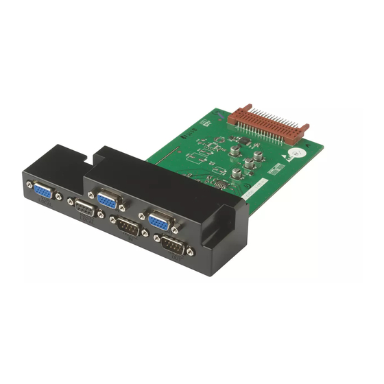
9-pin D-SUB Female E. Installation Instructions 1. Turn off the power to your Philips monitor and disconnect the power cable. 2. Place monitor face-down on a clean, non-abrasive surface. 3. Locate the SmartCard slot opening on the rear of the display. (see Fig. 2 below) - Page 4 4. Remove the SmartCard slot cap from the display by removing the two screws circled below. Keep the screws for use in step 8. 5. Remove the hex nuts from the high-rise 15-pin D-SUB connectors as shown below with a 5mm nut driver tool.
- Page 5 7. Insert the LT card into the SmartCard slot as shown below. Ensure that the card is securely connected to the internal 32-pin socket. 8. Secure the LT card to the display by re-fastening the screws that were removed in step 4. 9.
-
Page 6: Connection Instructions
F. Connection Instructions 1. VGA The diagram below illustrates the VGA connection configuration to a PC and multiple displays. Important note: The VGA cable from the PC to the first display should be type E101344 with all 15 pins available to ensure EDID read out. BDLX231 VGA In CRA01... -
Page 7: Troubleshooting
2. RS232 (Serial Communications) The diagram below illustrates the RS232 connection configuration to a PC and multiple displays. BDLX231 RS232 In CRA01 *DB9 F-M (cross cable) (cross cable) DB9 F-F (cross cable) G. Troubleshooting There is no image on the “head” display (the unit that initially receives source input) 1. - Page 8 For RS232 only at least 10 units can be daisy chained. Maximum distance between signal source and the last daisy chained display Philips recommends not to exceed 30 meters / 98 feet between the signal source (usually a PC) and last daisy chained display.
- Page 9 LT Card (CRA01/00) Installation Guide Page 9 of 9 LT Installation Guide 1.1 (140907) 12NC: 3139 125 39281...