Table of Contents
Advertisement
Quick Links
g
GE Power Management
269Plus
Motor Management Relay
Instruction Manual
Firmware Revision: 269P.E6.0.4
Manual P/N: 1601-0013-E2 (GEK-106287A)
Copyright © 2002 GE Power Management
G E P o w e r M a n a g e m e n t
215 Anderson Avenue, Markham, Ontario
Canada L6E 1B3
Tel: (905) 294-6222 Fax: (905) 294-8512
Internet:
h t t p : / / w w w . G E i n d u s t r i a l . c o m / p m
Manufactured under an
ISO9001 Registered system.
Courtesy of NationalSwitchgear.com
Advertisement
Chapters
Table of Contents

Related Manuals for GE 269Plus


Summary of Contents for GE 269Plus
- Page 1 Instruction Manual Firmware Revision: 269P.E6.0.4 Manual P/N: 1601-0013-E2 (GEK-106287A) Copyright © 2002 GE Power Management G E P o w e r M a n a g e m e n t 215 Anderson Avenue, Markham, Ontario Canada L6E 1B3...
- Page 2 Courtesy of NationalSwitchgear.com...
- Page 3 These instructions do not purport to cover all details or variations in equipment nor provide for every possible contingency to be met in connection with installation, operation, or main- tenance. Should further information be desired or should particular problems arise which are not covered sufficiently for the purchaser’s purpose, the matter should be referred to the General Electric Company.
- Page 4 Courtesy of NationalSwitchgear.com...
-
Page 5: Table Of Contents
TRIP/ALARM MODE................3-43 PHASE CT & MOTOR FULL LOAD CURRENT SETPOINTS....3-47 ACCELERATION TIME SETPOINT ............3-47 3.10 INHIBITS....................3-48 3.11 UNBALANCE SETPOINTS..............3-49 3.12 GROUND FAULT (EARTH LEAKAGE) SETPOINTS......3-50 GE Power Management 269Plus Motor Management Relay Courtesy of NationalSwitchgear.com... - Page 6 GROUND FAULT CURRENT FUNCTIONS ..........5-4 RTD MEASUREMENT TESTS ..............5-4 POWER FAILURE TESTING..............5-5 ANALOG CURRENT OUTPUT..............5-5 ROUTINE MAINTENANCE VERIFICATION ..........5-5 DIELECTRIC STRENGTH (HI-POT) TEST ..........5-6 269Plus Motor Management Relay GE Power Management Courtesy of NationalSwitchgear.com...
- Page 7 VIEWING ACTUAL VALUES ..............8-10 8.12 TRENDING ....................8-12 8.13 USING THE TROUBLESHOOTING FEATURE ........8-13 9. COMMISSIONING 269PLUS COMMISSIONING SUMMARY ..........9-1 REVISION HISTORY................. 9-5 A. 269 PLUS UNBALANCE DESCRIPTION ..................A-1 EXAMPLE ....................A-1 EXAMPLE B. THERMAL MODEL &...
- Page 8 DESCRIPTION ..................E-1 STARTING CURRENT F. DOs AND DON’Ts DESCRIPTION ..................F-1 DOs......................F-1 a 269PLUS GROUNDING ................F-1 b GROUNDING OF PHASE AND GROUND CTS........F-1 c RTDS ......................F-1 d RS485 COMMUNICATIONS PORT ............F-2 DON’Ts ...................... F-3 G.
-
Page 9: Motor Protection Requirements
The relay also monitors the motor and mechanical load for faults and problems. With the addition of a GE Power Management Motor Protection Meter (MPM), the 269Plus may also monitor voltages and power and perform several protection functions based on these values. - Page 10 When an output relay becomes active, the 269Plus will display the cause of the trip, and if applicable, the lock- out time remaining. Pre-trip values of average and individual line motor current, unbalance, ground fault cur- rent, and maximum stator RTD temperature are stored by the 269Plus and may be recalled using the keypad.
-
Page 11: Table 1-1: 269Plus Relay Features
1 INTRODUCTION FEATURES Table 1–1: 269Plus RELAY FEATURES PROTECTION FEATURES • Overloads • Stator Winding Overtemperature (Alarm, High Alarm and Trip) • Multiple Starts • Short Circuit • Locked Rotor • Rapid Trip/Mechanical Jam • Unbalance/Single Phasing • Ground Fault (Alarm and Trip) •... -
Page 12: Typical Applications
1 INTRODUCTION 1.3 TYPICAL APPLICATIONS The many features of the 269Plus make it an ideal choice for a wide range of motor protection applications. Versatile features and controls allow the relay to protect associated mechanical equipment as well as the motor. -
Page 13: Order Code / Information
2. FS = Fail safe: A fail safe relay is one that changes state when control power is applied to the 269/269Plus. NFS = Non fail safe: A non fail safe relay is one that remains on its shelf state when control power is applied to the 269/269Plus. -
Page 14: Technical Specifications
(contact closure to output relay acti- COMMUNICATIONS vation) Type: RS485 2-wire, half duplex, isolated Baud Rate: 300, 1200, 2400 ® Protocol: Subset of Modbus Functions: Read/write setpoints (03/16), Read actual values (03/04) 269Plus Motor Management Relay GE Power Management Courtesy of NationalSwitchgear.com... - Page 15 To avoid electrical shock, discharge J201 by shorting across the pins before reconnecting G/F CT 0.08 (5A) the J201 jumper. WARNING 696 Ω G/F CT 0.025 0.435 (50:0.025) 329 Ω 3.29 200 Ω GE Power Management 269Plus Motor Management Relay Courtesy of NationalSwitchgear.com...
- Page 16 Pollution Degree: tion IP Code: Altitude Rating: 2000m IEC 1010-1 The 269Plus Drawout does not meet CE compliance. HAZARD may result if the product is not used for intended purposes. WARNING This equipment can only be serviced by trained personnel. WARNING...
-
Page 17: Mpm Option Specifications
90 to 300 V DC or 70 to 265 V AC, 50/60 Hz Power: nominal 10 VA maximum 20 VA Holdup: 100 ms typical (@ 120 V AC/125 V DC) GE Power Management 269Plus Motor Management Relay Courtesy of NationalSwitchgear.com... - Page 18 MPM OPTION SPECIFICATIONS 1 INTRODUCTION 269Plus Motor Management Relay GE Power Management Courtesy of NationalSwitchgear.com...
-
Page 19: Installation
If the chosen CT is relatively small, the resolution (increments of current) displayed will also be small. Example: If the Phase CT selected is 50:1 or 5, then the 269Plus displays current in increments of 1 A (0.78 A rounded). Likewise, if the Phase CT is selected as 1500:1 or 5, the currents will be displayed in increments of 24 A (23.5 A rounded). - Page 20 PHYSICAL DIMENSIONS 2 INSTALLATION Figure 2–2: PHASE CT DIMENSIONS 269Plus Motor Management Relay GE Power Management Courtesy of NationalSwitchgear.com...
- Page 21 2 INSTALLATION PHYSICAL DIMENSIONS Figure 2–3: GROUND CT (50:0.025) 3” & 5” WINDOW GE Power Management 269Plus Motor Management Relay Courtesy of NationalSwitchgear.com...
- Page 22 PHYSICAL DIMENSIONS 2 INSTALLATION Figure 2–4: GROUND CT (50:0.025) 8” WINDOW 269Plus Motor Management Relay GE Power Management Courtesy of NationalSwitchgear.com...
- Page 23 2 INSTALLATION PHYSICAL DIMENSIONS Figure 2–5: GROUND CT ( x :5) DIMENSIONS GE Power Management 269Plus Motor Management Relay Courtesy of NationalSwitchgear.com...
-
Page 24: Mounting
2.2 MOUNTING The 269Plus should be positioned so that the display is visible and the front panel keypad is accessible. A cut- out is made in the mounting panel and the unit is mounted as shown below. Four washers and ten 32 × 3/8"... -
Page 25: Table 2-1: 269Plus External Connections
Relay contacts must be considered unsafe to touch when the system in energized! WARNING Once correct control power is applied to the 269Plus relay, a clicking sound will be heard approxi- mately every second. This normal operation indicates that the relay is scanning through the RTDs regardless if RTDs are in use. -
Page 26: External Connections
EXTERNAL CONNECTIONS 2 INSTALLATION Figure 2–7: RELAY WIRING DIAGRAM (AC CONTROL POWER) 269Plus Motor Management Relay GE Power Management Courtesy of NationalSwitchgear.com... - Page 27 In this case, it is also recommended that the AUX2 contacts be monitored for relay failure. If, however, the motor is more critical than the "process," then the trip contacts should be programmed failsafe. GE Power Management 269Plus Motor Management Relay Courtesy of NationalSwitchgear.com...
- Page 28 EXTERNAL CONNECTIONS 2 INSTALLATION Figure 2–9: RELAY WIRING DIAGRAM (TWO PHASE CTs) 269Plus Motor Management Relay GE Power Management Courtesy of NationalSwitchgear.com...
- Page 29 2 INSTALLATION EXTERNAL CONNECTIONS Figure 2–10: RELAY WIRING DIAGRAM (DC CONTROL POWER) GE Power Management 269Plus Motor Management Relay Courtesy of NationalSwitchgear.com...
-
Page 30: Control Power
If control power is removed, the relay keeps track of the Motor Lockout time for up to an hour. Control power must be applied to the 269Plus relay, and the relay programmed, before the motor is energized. Power is applied at Terminals 41, 42, and 43 which are terminal blocks having #6 screws. - Page 31 2 INSTALLATION CONTROL POWER Figure 2–11: REPLACING A BLOWN FUSE GE Power Management 269Plus Motor Management Relay Courtesy of NationalSwitchgear.com...
-
Page 32: Phase Ct Inputs
75 and 100% of the rated CT primary current. The CT ratio should thus be of the form n :1 or n :5 where n is between 20 and 1500. The ratio of the CT used must be programmed into the 269Plus (see Section : on page 3–46). - Page 33 The connections to the 269Plus internal ground CT are made directly via #10 screws. The ground CT is con- nected to Terminals 72 and 73 for a 5 A secondary CTs, or to Terminals 73 and 74 for GE Power Management 50:0.025A (2000:1 ratio) CTs, as shown in Figures 2–7: RELAY WIRING DIAGRAM (AC CONTROL POWER),...
-
Page 34: Ground Ct Input
GROUND CT INPUT 2 INSTALLATION Figure 2–12: CORE BALANCE GROUND CT INSTALLATION (SHIELDED CABLE) Figure 2–13: CORE BALANCE GROUND CT INSTALLATION (UNSHIELDED CABLE) 269Plus Motor Management Relay GE Power Management Courtesy of NationalSwitchgear.com... -
Page 35: Trip Relay Contacts
The Trip output relay will remain latched after a trip. This means that once this relay has been activated it will remain in the active state until the 269Plus is manually reset. The Trip relay contacts may be reset by pressing the RESET key (see Section 3.1: FRONT PANEL) if motor conditions allow, or by using the Emergency Restart... -
Page 36: Alarm Relay Contacts
Auxiliary relay #1 is provided to give an extra set of NO/NC contacts which operate independently of the other relay contacts (on a Drawout version of the 269Plus, only one set of Aux.1 contacts is available and the user must specify normally open or normally closed and failsafe or non-failsafe when ordering). This auxiliary relay has the same ratings as the Trip relay. -
Page 37: Auxiliary Relay #2 Contacts
This relay provides another set of NO/NC contacts with the same ratings as the other relays (on a drawout ver- sion of 269Plus, only one set of AUX. 2 contacts is available and the user must specify normally open or nor- mally closed when ordering). -
Page 38: Emergency Restart Terminals
5 of SETPOINTS mode. If no RTD sensor is to be connected to any RTD terminals on the 269Plus, the terminals may be left open. If less than 6 stator RTDs are to be employed, they should be connected to the lowest numbered relay RTD connections. -
Page 39: External Reset Terminals
RESET key. Keeping the External Reset terminals shorted together will cause the 269Plus to be reset automatically whenever motor conditions allow. A twisted pair of wires should be used. Connection to the 269Plus is made via a terminal block which can accommodate up to #16 AWG multi-strand wire. -
Page 40: Speed Switch Terminals
Setpoints page 6. See Section a): STARTS/HOUR TIMER on page 3–15 for further details. A twisted pair of wires should be used for connection to an external switch. Connection to the 269Plus is made via a terminal block which can accommodate up to #16 AWG multi-strand wire. - Page 41 If a large difference in ground potentials exists, serial communication will not be possible. Therefore, it is imperative that the serial master and 269Plus slave are both at the same ground potential. This is accomplished by joining Terminal 88 of every unit together and grounding it at the master only. If a...
-
Page 42: Display Adjustment
Do not connect live circuits. Dry contacts connections only. WARNING A twisted pair of wires should be used. Connection to the 269Plus is made via a terminal block which can accommodate up to #16 AWG multi-strand wire. 269Plus Motor Management Relay GE Power Management Courtesy of NationalSwitchgear.com... - Page 43 2.22 DRAWOUT RELAY OPTION The 269Plus is available in a drawout case option. The operation of the relay is the same as described else- where in this manual except for the differences noted in this section. The physical dimensions of the drawout relay are as shown in Figure 2–16: DRAWOUT RELAY PHYSICAL DIMENSIONS on page 2–26.
-
Page 44: Drawout Relay Option
DRAWOUT RELAY OPTION 2 INSTALLATION FIGURE 2–16: DRAWOUT RELAY PHYSICAL DIMENSIONS 269Plus Motor Management Relay GE Power Management Courtesy of NationalSwitchgear.com... - Page 45 2 INSTALLATION DRAWOUT RELAY OPTION FIGURE 2–17: DRAWOUT RELAY MOUNTING GE Power Management 269Plus Motor Management Relay Courtesy of NationalSwitchgear.com...
- Page 46 DRAWOUT RELAY OPTION 2 INSTALLATION Figure 2–18: DRAWOUT RELAY TYPICAL WIRING DIAGRAM 269Plus Motor Management Relay GE Power Management Courtesy of NationalSwitchgear.com...
-
Page 47: Mpm Wiring
METER OPTION INSTALLATION 2.23 METER OPTION INSTALLATION The addition of a GE Power Management MPM (Motor Protection Meter) option allows the 269Plus user to monitor and assign protective features based on voltage and power measurement. The MPM also provides four isolated analog outputs representing current, watts, vars, and power factor. These meter outputs can pro- vide the signals for the control of the motor or a process. -
Page 48: D Vt Inputs (1-4)
CTs should be selected to be capable of supplying the required current to the total secondary load which includes the MPM relay burden of 0.2 VA at rated secondary current and the connection wiring burden. 269Plus Motor Management Relay GE Power Management... -
Page 49: Mpm Analog Output
SERIAL COMMUNICATIONS PORT (COM1 - 46,47,48) The MPM communicates with the 269Plus via COM1. The connection must be made as shown below. The MPM must be connected to only one 269Plus relay at any given time for successful communication. - Page 50 METER OPTION INSTALLATION 2 INSTALLATION Figure 2–21: MPM MOUNTING DIMENSIONS 269Plus Motor Management Relay GE Power Management Courtesy of NationalSwitchgear.com...
- Page 51 2 INSTALLATION METER OPTION INSTALLATION Figure 2–22: MPM TO 269 PLUS TYPICAL WIRING (4-WIRE WYE, 3 VTs) GE Power Management 269Plus Motor Management Relay Courtesy of NationalSwitchgear.com...
- Page 52 METER OPTION INSTALLATION 2 INSTALLATION Figure 2–23: MPM TO 269 PLUS TYPICAL WIRING (4-WIRE WYE, 2 VTs) 269Plus Motor Management Relay GE Power Management Courtesy of NationalSwitchgear.com...
- Page 53 2 INSTALLATION METER OPTION INSTALLATION Figure 2–24: MPM TO 269 PLUS TYPICAL WIRING (3-WIRE DELTA, 2 VTs) GE Power Management 269Plus Motor Management Relay Courtesy of NationalSwitchgear.com...
- Page 54 METER OPTION INSTALLATION 2 INSTALLATION Figure 2–25: MPM TO 269 PLUS TYPICAL WIRING (2 CT) 269Plus Motor Management Relay GE Power Management Courtesy of NationalSwitchgear.com...
- Page 55 2 INSTALLATION METER OPTION INSTALLATION Figure 2–26: MPM WIRING (OPEN DELTA) GE Power Management 269Plus Motor Management Relay Courtesy of NationalSwitchgear.com...
- Page 56 METER OPTION INSTALLATION 2 INSTALLATION 269Plus Motor Management Relay GE Power Management Courtesy of NationalSwitchgear.com...
-
Page 57: Setup And Use
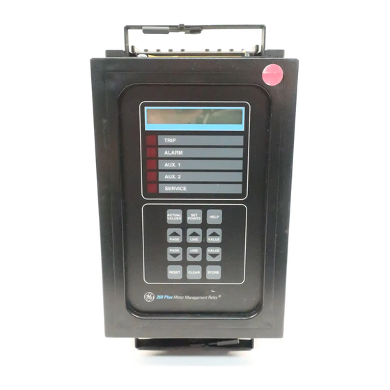
269 INSTRUCTION MANUAL 3 SETUP AND USE 3.1 FRONT PANEL Once the 269Plus has been wired and control power applied, it is ready to be programmed. Programming is accomplished using the 12-position keypad and 48-character alphanumeric display shown below. The function of the keypad and indicators is briefly explained in Table 3–1: CONTROLS AND INDICATORS on page 3–2. -
Page 58: Controls And Indicators
2: RTD Setpoints page 3: O/L Curve Setpoints page 4: Relay Configuration page 5: System Configuration page 6: GE Power Management Service Codes page 7: Metering Setpoints EFFECT: This key places the relay into SETPOINTS mode. The flash message, SETPOINTS HAS SEVEN... - Page 59 [LINE M] key has no effect. Likewise, if the the first line of a LINE page is displayed, the [LINE L] key has no effect. GE Power Management 269Plus Motor Management Relay Courtesy of NationalSwitchgear.com...
- Page 60 Use the [STORE] key to save the desired setpoint value. If an altered setpoint is not stored, the previous value remains in effect. FUNCTION: The [RESET] key allows resets the 269Plus after any of the latched output relays have become active so that a motor start can be attempted.
- Page 61 LED indicator used to show the result of the self-test feature. When flashing, the relay has failed the self-test and service is required. When on steady, the supply voltage may be too low. This LED may be on momentarily during relay power up. GE Power Management 269Plus Motor Management Relay Courtesy of NationalSwitchgear.com...
-
Page 62: Relay Display Modes
3 SETUP AND USE 3.3 RELAY DISPLAY MODES The 269Plus display is used for viewing actual motor values, setpoint values, HELP messages, and TRIP/ ALARM messages. This is accomplished by having the relay in one of four possible modes of operation: 1. -
Page 63: Actual Values Mode
3.4 ACTUAL VALUES MODE In ACTUAL VALUES mode, any of the parameters monitored or calculated by the 269Plus may be viewed by the user. This mode is divided into seven separate pages of data, each of which contains a different group of actual motor values. - Page 64 ACTUAL VALUES MODE 3 SETUP AND USE Table 3–2: 269Plus ACTUAL VALUES (Sheet 2 of 9) PAGE LINE INFORMATION LINE DESCRIPTION ACTUAL VALUES PAGE 2: RTD TEMPERATURE DATA Actual Values page 2 header. In all page 2 PAGE 2: ACTUAL VALUES messages, temperatures are displayed in °C...
- Page 65 3 SETUP AND USE ACTUAL VALUES MODE Table 3–2: 269Plus ACTUAL VALUES (Sheet 3 of 9) PAGE LINE INFORMATION LINE DESCRIPTION 9 ‡ RTD #6 temperature. STATOR TEMPERATURE RTD #6= XXX DEGREEES C RTD TEMPERATURE RTD #6= XXX DEGREES C 10 ‡...
- Page 66 ACTUAL VALUES MODE 3 SETUP AND USE Table 3–2: 269Plus ACTUAL VALUES (Sheet 4 of 9) PAGE LINE INFORMATION LINE DESCRIPTION Last line of page 2. END OF PAGE TWO ACTUAL VALUES ACTUAL VALUES PAGE 3: MOTOR CAPACITY DATA Actual Values page 3 header.
- Page 67 3 SETUP AND USE ACTUAL VALUES MODE Table 3–2: 269Plus ACTUAL VALUES (Sheet 5 of 9) PAGE LINE INFORMATION LINE DESCRIPTION Total number of relay rapid trips since last # RAPID TRIPS SINCE LAST commissioning. COMMISSIONING Total number of relay unbalance trips since last # U/B TRIPS SINCE LAST commissioning.
-
Page 68: Cause Of Last Trip
ACTUAL VALUES MODE 3 SETUP AND USE Table 3–2: 269Plus ACTUAL VALUES (Sheet 6 of 9) PAGE LINE INFORMATION LINE DESCRIPTION This message is only displayed (and defaulted to) XXXXXXXXXXX when a trip or alarm occurs and describes the trip/ alarm condition. - Page 69 3 SETUP AND USE ACTUAL VALUES MODE Table 3–2: 269Plus ACTUAL VALUES (Sheet 7 of 9) PAGE LINE INFORMATION LINE DESCRIPTION 15 † Power factor prior to last relay trip. The lead or lag PRE-TRIP POWER FACTOR messages are also captured and displayed prior to PF = X.XX LAG...
- Page 70 ACTUAL VALUES MODE 3 SETUP AND USE Table 3–2: 269Plus ACTUAL VALUES (Sheet 8 of 9) PAGE LINE INFORMATION LINE DESCRIPTION Learned motor thermal capacity used since last LEARNED Start Capacity start. See 3.21: THERMAL CAPACITY ALARM on Last Start T.C. = XXX % page 3–59 for details on using this value to adapt...
-
Page 71: A Starts/Hour Timer
3 SETUP AND USE ACTUAL VALUES MODE Table 3–2: 269Plus ACTUAL VALUES (Sheet 9 of 9) PAGE LINE INFORMATION LINE DESCRIPTION 6 † Positive or negative 3 phase kvars. See Figure 3–8: 3 PHASE KVARS POWER MEASUREMENT CONVENTIONS. KVAR = +XXXXX 7 †... -
Page 72: B Time Between Starts Timer
5% of CT. 5% of CT is the cutoff point for the 269Plus, where a motor stop condition is registered. In this case, the cause of the last trip is not updated. - Page 73 All seven pages of data and the lines in each page are as shown in Table 3–3: 269Plus SETPOINTS on page 3–18. Also shown are the default settings, the ranges and increments for each setpoint. It should be noted that the 269Plus motor protection parameters are based on the data entered by the user.
-
Page 74: Setpoints Mode
SETPOINTS MODE 3 SETUP AND USE TABLE 3–3: 269PLUS SETPOINTS (SHEET 1 OF 25) PAGE LINE INFORMATION LINE SETPOINTS PAGE 1: MOTOR AMPS SETPOINTS PAGE 1: SETPOINT VALUES MOTOR AMPS SETPOINTS Range: 1, 5 PHASE CT RATIO Factory Value: 5; Manual Reference: 3.7... -
Page 75: Table : 3-3 269P Lus Setpoints
3 SETUP AND USE SETPOINTS MODE TABLE 3–3: 269PLUS SETPOINTS (SHEET 2 OF 25) PAGE LINE INFORMATION LINE Range: For 5 A secondary CT, 0.1 to 1.0 x CT rating GROUND FAULT ALARM LEVEL or OFF, in steps of 0.1 (not seen if ratio is 2000:1) G/F ALARM= XXX xCT Factory Value = 0.4 x CT;... - Page 76 SETPOINTS MODE 3 SETUP AND USE TABLE 3–3: 269PLUS SETPOINTS (SHEET 3 OF 25) PAGE LINE INFORMATION LINE Range: 1.01 to 1.50 ×FLC or OFF, in steps of 0.01 IMMEDIATE OVERLOAD Factory Value = OFF; Manual Reference: 3.17 LEVEL = X.XX x FLC...
- Page 77 3 SETUP AND USE SETPOINTS MODE TABLE 3–3: 269PLUS SETPOINTS (SHEET 4 OF 25) PAGE LINE INFORMATION LINE Range: 0 to 200°C or OFF, in steps of 1°C (32 to 392°F STATOR #2 ALARM LEVEL in steps of 1°F if Fahrenheit)
- Page 78 SETPOINTS MODE 3 SETUP AND USE TABLE 3–3: 269PLUS SETPOINTS (SHEET 5 OF 25) PAGE LINE INFORMATION LINE Range: 0 to 200°C or OFF, in steps of 1°C STATOR #4 ALARM LEVEL (32 to 392°F in steps of 1°F if Fahrenheit) XXX DEGREES C Factory Value = OFF;...
- Page 79 3 SETUP AND USE SETPOINTS MODE TABLE 3–3: 269PLUS SETPOINTS (SHEET 6 OF 25) PAGE LINE INFORMATION LINE Range: 0 to 200°C or OFF, in steps of 1°C STATOR #6 ALARM LEVEL (32 to 392°F in steps of 1°F if Fahrenheit) XXX DEGREES C Factory Value = OFF;...
- Page 80 SETPOINTS MODE 3 SETUP AND USE TABLE 3–3: 269PLUS SETPOINTS (SHEET 7 OF 25) PAGE LINE INFORMATION LINE END OF PAGE TWO SETPOINT VALUES SETPOINTS PAGE 3: O/L CURVE SETPOINTS NOTE: Lines 4 through 25 are not seen when PAGE 3: SETPOINT VALUES using a standard curve.
- Page 81 3 SETUP AND USE SETPOINTS MODE TABLE 3–3: 269PLUS SETPOINTS (SHEET 8 OF 25) PAGE LINE INFORMATION LINE Range: 1 to 2000 sec., step 1 TRIP TIME @ 2.50 X FLC Manual Reference: 3.20 XXXXX SECONDS This line is not seen when using a standard curve Range: 1 to 2000 sec., step 1...
- Page 82 SETPOINTS MODE 3 SETUP AND USE TABLE 3–3: 269PLUS SETPOINTS (SHEET 9 OF 25) PAGE LINE INFORMATION LINE SETPOINTS PAGE 4: RELAY CONFIGURATION PAGE 4: SETPOINT VALUES RELAY CONFIGURATION This page assigns trip and alarm functions to the output relays. Each trip/alarm function is assigned separately to the appropriate relay or to "NO"...
- Page 83 This setpoint determines the line of the selected Actual Values page to display if no key is pressed for more than four minutes and no trips or alarms are present. Range: 1 to 40 – line number in selected page (see Table 3–2: 269Plus ACTUAL VALUES) Factory Value = 2...
- Page 84 SETPOINTS MODE 3 SETUP AND USE TABLE 3–3: 269PLUS SETPOINTS (SHEET 11 OF 25) PAGE LINE INFORMATION LINE ENABLE STATOR RTD VOTING (2 RTDs>=TRIP)? This setpoint enables or defeats the stator RTD voting feature. If enabled, any one Stator RTD alone will not trip the motor even when it exceeds its trip setpoint. A minimum of two stator RTDs must exceed their individual trip setpoints before a trip signal is issued.
- Page 85 3 SETUP AND USE SETPOINTS MODE TABLE 3–3: 269PLUS SETPOINTS (SHEET 12 OF 25) PAGE LINE INFORMATION LINE RTD BIAS CENTER TEMP. VALUE = XXX C Not seen when (Setpoints page 5, line 7) is defeated. R T D I N P U T T O T H E R M A L M E M O R Y This is the temperature value for the center point of the two part curve.
- Page 86 DEFEAT LEARNED COOL TIME? XX This setpoint tells the 269Plus to use the learned motor cooling time values. (see Actual Vales page 6). When learned values are not used, the user entered values are used. Range: YES (default cool times); NO (learned cool times from Actual Values page 6) This setpoint should not be changed unless the 269Plus has learned reasonable motor cool down times.
- Page 87 3 SETUP AND USE SETPOINTS MODE TABLE 3–3: 269PLUS SETPOINTS (SHEET 14 OF 25) PAGE LINE INFORMATION LINE DEFEAT SPEED SWITCH This setpoint is used to defeat or enable the Speed Switch trip. Range: YES (speed Switch function disabled); NO (speed Switch function enabled)
- Page 88 SETPOINTS MODE 3 SETUP AND USE TABLE 3–3: 269PLUS SETPOINTS (SHEET 15 OF 25) PAGE LINE INFORMATION LINE Enable start inhibit? This setpoint is used to enable or disable the start inhibit feature. This setpoint should not be changed until a reasonable value has been obtained for the L E A R N E D S T A R T C A P A C I T Y R E Q U I R E D (Actual Values page 6) Range: YES, NO.
- Page 89 3 SETUP AND USE SETPOINTS MODE TABLE 3–3: 269PLUS SETPOINTS (SHEET 16 OF 25) PAGE LINE INFORMATION LINE DRAWOUT FAILSAFE ACCESS CODE = 0 (See manual) This setpoint appears only if the relay is a drawout. Entering value from factory for this setpoint allows access of the failsafe codes for approximately 3 minutes.
- Page 90 Y E S If this setpoint is , the 269Plus detects a motor stop condition when current drops below 5% of CT. This may result in nuisance lockouts if the motor (synchronous or induction) is running unloaded or idling, and if the starts/hour or time between starts are programmed.
- Page 91 3 SETUP AND USE SETPOINTS MODE TABLE 3–3: 269PLUS SETPOINTS (SHEET 18 OF 25) PAGE LINE INFORMATION LINE FLC THERMAL CAPACITY REDUCTION = XX PERCENT This setpoint sets the level which the thermal memory will discharge to when the motor is running at full load current.
- Page 92 PAGE 6: SETPOINT VALUES GE MULTILIN SERVICE CODES This page is used for 269Plus relay testing both in the field and at the GE Power Management. The first five lines of this page are available to the user for testing the relay once it is installed.
- Page 93 Range: 0 to 500 or OFF, in steps of 1 (OFF disables the software access feature). Factory Value = OFF SERVICE USE ONLY CODE = XX This line is used by GE Power Management service personnel for calibration and service. CAN.SERVICE: 905-294-6222 http://www.ge.com/edc/pm Canadian and United States service phone number and web site.
- Page 94 SETPOINTS PAGE 7: METERING SETPOINTS PAGE 7: SETPOINT VALUES METERING SETPOINTS This page enable the 269Plus to display and/or trip and alarm on voltage or power values received from a GE Power Management MPM meter. METERING SETPOINTS SET AND METER ONLINE? XXX This setpoint enables 269Plus communications with a GE Power Management meter.
- Page 95 3 SETUP AND USE SETPOINTS MODE TABLE 3–3: 269PLUS SETPOINTS (SHEET 22 OF 25) PAGE LINE INFORMATION LINE METER PHASE VT SECONDARY VT SECONDARY = XXX VOLT Enter the VT secondary of the voltage transformer connected between the system and the meter.
- Page 96 SETPOINTS MODE 3 SETUP AND USE TABLE 3–3: 269PLUS SETPOINTS (SHEET 23 OF 25) PAGE LINE INFORMATION LINE U/V TRIP TIME DELAY TIME DELAY = XXX SEC This line sets the time for an undervoltage trip condition to persist in order to facilitate a trip.
- Page 97 3 SETUP AND USE SETPOINTS MODE TABLE 3–3: 269PLUS SETPOINTS (SHEET 24 OF 25) PAGE LINE INFORMATION LINE BLOCK PF ALARM & TRIP ON START BY: XXX SECONDS When enabled, Power Factor alarm and trip protection are blocked from the time the motor starts until the time delay programmed expires.
- Page 98 SETPOINTS MODE 3 SETUP AND USE TABLE 3–3: 269PLUS SETPOINTS (SHEET 25 OF 25) PAGE LINE INFORMATION LINE POWER FACTOR TRIP TIME DELAY = XXX This line sets the time that a power factor trip condition must persist to facilitate a trip.
-
Page 99: Help Mode
HELP MODE 3.6 HELP MODE This display mode should be used whenever help is required using the 269Plus. The [HELP] key provides information on the proper function and use of each key and the currently displayed ACTUAL VALUES, SET- POINTS, or TRIP/ALARM message. Pressing [HELP] has no effect when a flash message or HELP message is displayed. -
Page 100: Trip/Alarm Mode
Check for motor winding shorts; Increase Trip Level if required. • • • • Available only if a GE Power Management meter (MPM) is installed and on-line (see Setpoints page 7, line 2) 269Plus Motor Management Relay GE Power Management... - Page 101 I(3 ph avg) = XXXX A RMS greater than the Undercurrent Alarm Time Delay. • • • • Available only if a GE Power Management meter (MPM) is installed and on-line (see Setpoints page 7, line 2) GE Power Management 269Plus Motor Management Relay...
- Page 102 METER FAILURE than the 269 Plus firmware. (INCOMPATIBLE REVISIONS) • • • • Available only if a GE Power Management meter (MPM) is installed and on-line (see Setpoints page 7, line 2) 269Plus Motor Management Relay GE Power Management Courtesy of NationalSwitchgear.com...
-
Page 103: Phase Ct & Motor Full Load Current Setpoints
In the case where a motor may idle at less than 5% of rated CT primary Amps (i.e. synchronous motor) it is imperative that a 52b contact is input to the 269Plus (52b contact reflects the opposite state of the breaker). -
Page 104: Inhibits
An Inhibit is a feature that becomes active only once a motor STOP condition has been detected and prevents motor starting until the Inhibit has timed out. There are four Inhibit features in the 269Plus. They are S T A R T S / , and . -
Page 105: Unbalance Setpoints
Persistent, minor voltage unbalance can thus lead to rotor thermal damage while severe unbalance such as single phasing can very quickly lead to a motor burnout. For phase currents above 100% FLC, the 269Plus calculates the ratio of the negative to positive sequence cur- rents ( I ) and uses this ratio in two seperate protective functions. -
Page 106: Ground Fault (Earth Leakage) Setpoints
(time delays) may also be set. The ground fault trip can be instantaneous, or up to 20.0 seconds of time delay can be chosen to allow the 269Plus to be coordinated with other protective devices and switchgear. -
Page 107: Contactor/Breaker Wiring
3 SETUP AND USE CONTACTOR/BREAKER WIRING 3.13 CONTACTOR/BREAKER WIRING Figure 3–2: WIRING DIAGRAM FOR CONTACTORS Figure 3–3: WIRING DIAGRAM FOR BREAKERS GE Power Management 269Plus Motor Management Relay Courtesy of NationalSwitchgear.com... -
Page 108: Undercurrent Setpoints
When using this feature be certain that the interrupting device can safely open to break the short circuit duty. Otherwise this setpoint must be set to . Other means of interrupting fault O F F currents must then be used (e.g. fuses). WARNING 269Plus Motor Management Relay GE Power Management Courtesy of NationalSwitchgear.com... -
Page 109: Immediate Overload Alarm Setpoint
3.18 STATOR RTD SETPOINTS The 269Plus is ordered with one of the following RTD types: 100 Ω platinum, 10 Ω copper, 100 Ω nickel, or 120 Ω nickel. Setpoints page 2, line 2, indicates the type of RTD built into the relay. It is possible to operate the 269Plus without connecting any RTDs. -
Page 110: Other Rtd Setpoints
L O W T E M P E R A T U R E A L A R M Alarm mode to warn the user of any one RTD measuring 0° ° ° ° C (32° ° ° ° F). The 269Plus can detect shorted RTDs in motors where the normal running temperature, hence stator RTD and bearing RTD temperature, is not 0°... - Page 111 Thus the times on the overload curve may be reduced due to phase current unbalance (see Sec- tion 3.22: THERMAL MEMORY). A choice of eight standard curves, as shown in Figure 3–5: STANDARD OVERLOAD CURVES on page 3–57, is available for the 269Plus. Figure 3–4: STANDARD OVERLOAD CURVES WITH OVERLOAD PICKUP...
-
Page 112: Overload Curve Setpoints
If a new standard curve number or custom curve point is stored while the motor is running, the new curve or point will not come into effect until the motor has stopped. NOTE Table 3–5: STANDARD OVERLOAD CURVE TRIP TIMES (IN SECONDS) OVERLOAD GE POWER MANAGEMENT CURVE NUMBER LEVEL 1.05 1707 2560... - Page 113 CURVE 7 CURVE 6 CURVE 5 CURVE 4 CURVE 3 CURVE 2 CURVE 1 FULL LOAD CURRENT SETPOINT MULTIPLES OF FULL LOAD CURRENT SETPOINTT 968516A7.CDR Figure 3–5: STANDARD OVERLOAD CURVES GE Power Management 269Plus Motor Management Relay Courtesy of NationalSwitchgear.com...
- Page 114 OVERLOAD CURVE SETPOINTS 3 SETUP AND USE If the standard curves do not sufficiently match the motor data, the 269Plus allows for the creation of a custom overload curve. Motors with non-standard overload charactersitics can be fully protected since almost any curve shape can be entered.
-
Page 115: Thermal Capacity Alarm
3.22 THERMAL MEMORY The 269Plus uses an internal thermal memory register to represent the thermal capacity of the motor. To "fill" this register, the square of the equivalent motor heating current is integrated over time. This equivalent current is a biased average of the 3 phase currents. -
Page 116: U/B Input To Thermal Memory
U/B INPUT TO THERMAL MEMORY When U/B input to thermal memory is defeated, the 269Plus will use the average of the three phase currents for all overload calculations (i.e. any time the overload curve is active). When U/B input to thermal memory is enabled the relay will use the equivalent motor heating current calculated as shown: (with U/B input to thermal memory disabled;... -
Page 117: Rtd Input To Thermal Memory
RTD values exceed the user's trip level for RTD trip, as defined in page 2 of setpoints. Additionally, RTD bias may artificially sustain lockout times for the O/L feature as it is based on thermal capacity. Figure 3–7: HOT MOTOR THERMAL CAPACITY REDUCTION GE Power Management 269Plus Motor Management Relay Courtesy of NationalSwitchgear.com... -
Page 118: Learned Cooling Times
All learned values can be examined in Actual Vales page 6. If RTDs are used to monitor the temperature of the motor stator the relay will learn the running and stopped cooling times of the motor. In this way the 269Plus provides increased accuracy in the thermal modeling of the protected motor. -
Page 119: Emergency Restart
When in this mode, the 269Plus suspends all learning functions and stops updating the learned parameters on Actual Values page 6 and the statistical parameters Actual Values page 4. Ensure that the 269Plus is returned to normal running mode by changing the above setpoint to If it is desired to enable the "Start inhibit"... -
Page 120: Resetting The Relay
3 SETUP AND USE 3.24 RESETTING THE RELAY Resetting the 269Plus after a trip must be done manually by pressing the RESET key or by shorting together the External Reset terminals. Alarm functions can cause latched (manual reset) or unlatched (automatic reset) output relay operation depending on the R E L A Y A L A R M L A T C H C O D E (see Setpoints page 5). -
Page 121: Relay Self-Test
The RTD test involves reading a known, internal resistance and checking to see if the correct temperature is determined. To test the memory circuitry, test data is stored in the 269Plus relay's non-volatile RAM and is then read and compared with the original data. -
Page 122: Meter Option
3 SETUP AND USE 3.28 METER OPTION The addition of a GE Power Management MPM meter to a 269Plus provides valuable voltage and power mea- surement. These values are good for troubleshooting and protective features. In order to install the MPM, all connections to the meter must be made. Then, the M E T E R P H A S E C T P R I M A R Y setpoints on Setpoints page 7 must be programmed. - Page 123 Such motors are typically used to correct a poor PF in an industrial plant. The 269Plus displays motor supplied vars as negative vars when a synchronous motor is running at synchronous speed, its power factor is unity and the vars required to run the motor are completely supplied by the field.
-
Page 124: The Phenomenon
NOTE On commissioning of a synchronous motor protected by a 269Plus and an MPM, correct wiring of the VTs and CTs is crucial for accurate measurement and protection. Typically, commissioning and testing starts with the motor unloaded. -
Page 125: Table 3-6: Preset Factory Relay Configurations And Functions
RTD Trip G/F Trip Acceleration Time Trip Phase Reversal Trip Inhibits Speed Switch Trip Differential Relay Trip Single Phase Trip Spare Input Trip U/V Trip O/V Trip Power Factor Trip GE Power Management 269Plus Motor Management Relay Courtesy of NationalSwitchgear.com... -
Page 126: Preset Configurations / Functions
PRESET CONFIGURATIONS / FUNCTIONS 3 SETUP AND USE 269Plus Motor Management Relay GE Power Management Courtesy of NationalSwitchgear.com... -
Page 127: Communications
The electrical interface is a two-wire bidirectional multi-drop RS485 on a shielded twisted-pair cable. A Belden 9841 insulated 24 gauge shielded twisted pair cable should be used. The connection to the 269Plus is by Ter- minals 46 (–) and 47 (+), where + is the positive wire and – is the negative wire. The shield must be connected at Terminal 88 on each 269Plus throughout the link and GROUNDED AT THE MASTER ONLY. - Page 128 PHYSICAL LAYER 4 COMMUNICATIONS Figure 4–1: SERIAL COMMUNICATION LINK 269Plus Motor Management Relay GE Power Management Courtesy of NationalSwitchgear.com...
-
Page 129: Packet Format
Communication with the 269Plus occurs in packets, which are groups of asynchronous bytes that are framed by silent time gaps. The packet format of Modbus RTU is adopted by the GE Power Management 269Plus relays. This format is as follows:... -
Page 130: The Handshake
The 269Plus is quite flexible in this regard: it replies when commanded, regardless of the com- mand being an original query or a repetition. - Page 131 FUNCTION 03h: READ SETPOINTS (HOLDING REGISTERS) The Modbus Read Holding Registers command is interpreted here as "Read 269Plus Setpoints". It is used by the master computer to program the relaying parameters. Up to 125 consecutive registers (250 bytes) can be read with one command.
-
Page 132: Supported Functions
269Plus setpoint registers. Although Modbus limits the number of registers that may be written to in a single command to 60, the 269Plus allows up to 125. The use of this function may not be authorized in some customer installations. Care must be taken when using this command and a soft- ware access code is highly recommended. -
Page 133: Exception Or Error Replies
EXCEPTION OR ERROR REPLIES 4.7 EXCEPTION OR ERROR REPLIES When the master command cannot be performed, the 269Plus replies with an error code. This is different from detecting communication related errors, such as CRC error for which the 269Plus ignores the command. -
Page 134: Error Checking Code
CRC code. If the two CRC codes do not match, an error has occurred. If an error is detected by the receiver, then the received command is not executed and the 269Plus will not respond. -
Page 135: Sample Packet With Crc-16
4.9 MEMORY MAP The 269Plus memory map is broken up into two areas: the Actual Values address space and the Setpoints address space. Each space has a total of 256 bytes. There are separate commands used to access the two different spaces. -
Page 136: Table : 4-2 269Plus Memory Map
MEMORY MAP 4 COMMUNICATIONS Table 4–2: 269PLUS MEMORY MAP (Sheet 1 of 14) A D D R E S S D E S C R I P T I O N R A N G E U N I T S... - Page 137 4 COMMUNICATIONS MEMORY MAP Table 4–2: 269PLUS MEMORY MAP (Sheet 2 of 14) A D D R E S S D E S C R I P T I O N R A N G E U N I T S...
- Page 138 MEMORY MAP 4 COMMUNICATIONS Table 4–2: 269PLUS MEMORY MAP (Sheet 3 of 14) A D D R E S S D E S C R I P T I O N R A N G E U N I T S...
- Page 139 4 COMMUNICATIONS MEMORY MAP Table 4–2: 269PLUS MEMORY MAP (Sheet 4 of 14) A D D R E S S D E S C R I P T I O N R A N G E U N I T S...
- Page 140 MEMORY MAP 4 COMMUNICATIONS Table 4–2: 269PLUS MEMORY MAP (Sheet 5 of 14) A D D R E S S D E S C R I P T I O N R A N G E U N I T S...
- Page 141 4 COMMUNICATIONS MEMORY MAP Table 4–2: 269PLUS MEMORY MAP (Sheet 6 of 14) A D D R E S S D E S C R I P T I O N R A N G E U N I T S...
- Page 142 MEMORY MAP 4 COMMUNICATIONS Table 4–2: 269PLUS MEMORY MAP (Sheet 7 of 14) A D D R E S S D E S C R I P T I O N R A N G E U N I T S...
- Page 143 4 COMMUNICATIONS MEMORY MAP Table 4–2: 269PLUS MEMORY MAP (Sheet 8 of 14) A D D R E S S D E S C R I P T I O N R A N G E U N I T S...
- Page 144 MEMORY MAP 4 COMMUNICATIONS Table 4–2: 269PLUS MEMORY MAP (Sheet 9 of 14) A D D R E S S D E S C R I P T I O N R A N G E U N I T S...
- Page 145 4 COMMUNICATIONS MEMORY MAP Table 4–2: 269PLUS MEMORY MAP (Sheet 10 of 14) A D D R E S S D E S C R I P T I O N R A N G E U N I T S...
- Page 146 MEMORY MAP 4 COMMUNICATIONS Table 4–2: 269PLUS MEMORY MAP (Sheet 11 of 14) A D D R E S S D E S C R I P T I O N R A N G E U N I T S...
- Page 147 4 COMMUNICATIONS MEMORY MAP Table 4–2: 269PLUS MEMORY MAP (Sheet 12 of 14) A D D R E S S D E S C R I P T I O N R A N G E U N I T S...
- Page 148 MEMORY MAP 4 COMMUNICATIONS Table 4–2: 269PLUS MEMORY MAP (Sheet 13 of 14) A D D R E S S D E S C R I P T I O N R A N G E U N I T S...
- Page 149 4 COMMUNICATIONS MEMORY MAP Table 4–2: 269PLUS MEMORY MAP (Sheet 14 of 14) A D D R E S S D E S C R I P T I O N R A N G E U N I T S...
-
Page 150: Format Codes
0000 0000 0000 1000 (N = non-failsafe, F = failsafe) 16 bits Analog Output Scale 0000 0000 0011 0010 4-20 mA 0000 0000 0011 0011 0-20 mA 0000 0000 0011 0100 0-1 mA 269Plus Motor Management Relay GE Power Management Courtesy of NationalSwitchgear.com... - Page 151 External Reset 0000 0000 0010 1000 Emergency Reset 0000 0000 0010 1001 Access 0000 0000 0010 1010 Speed Switch 0000 0000 0010 1011 Differential Input 0000 0000 0010 1100 Spare Input GE Power Management 269Plus Motor Management Relay Courtesy of NationalSwitchgear.com...
- Page 152 (DO NOT ALTER) 1000 0000 0000 0000 Clear Pre-Trip Data 16 bits Product Code 0000 0000 0011 0100 269 Plus Motor Management Relay 0000 0000 0001 0010 269 Motor Management Relay 269Plus Motor Management Relay GE Power Management Courtesy of NationalSwitchgear.com...
- Page 153 16 bits Motor Trip Status 1 0000 0000 0000 0001 Overload Trip 0000 0000 0000 0010 Unbalance Trip 0000 0000 0000 0100 Short Circuit Trip 0000 0000 0000 1000 Rapid Trip GE Power Management 269Plus Motor Management Relay Courtesy of NationalSwitchgear.com...
- Page 154 0000 0000 0000 0010 Motor in Overload (Iavg > Iflc) 0000 0000 0000 0011 Motor Starting 16 bits Inhibit Type 0000 0000 0011 0111 Starts per Hour 0000 0000 0011 1000 Start Inhibit 269Plus Motor Management Relay GE Power Management Courtesy of NationalSwitchgear.com...
- Page 155 0000 0000 0101 0011 Power Factor Trip 0000 0000 0101 0100 Undervoltage Trip 0000 0000 0101 0101 Overvoltage Trip 0000 0000 0101 0110 Undercurrent Trip 0000 0000 0101 0111 Undefined GE Power Management 269Plus Motor Management Relay Courtesy of NationalSwitchgear.com...
- Page 156 Analog to Digital (A/D) Hardware Failure Alarm 0000 0000 0001 0100 RTD Hardware (H/W) Failure Alarm 0000 0000 0001 0101 RAM Memory Failure Alarm 0000 0000 0001 1000 Board/PROM Mismatch Failure 269Plus Motor Management Relay GE Power Management Courtesy of NationalSwitchgear.com...
-
Page 157: Relay Testing
If the chosen CT is relatively small, the resolution (increments of current) displayed will also be small. For example, if the Phase CT selected is 50:1 or 5. the 269Plus displays current in increments of 1 A (0.78 A rounded). Likewise, if the Phase CT is selected as 1500:1 or 5, the current is displayed in increments of 24 A (23.5 rounded). -
Page 158: Phase Current Input Functions
PHASE CURRENT INPUT FUNCTIONS 5 RELAY TESTING FIGURE 5–1: SECONDARY INJECTION TEST (AC INPUT TO 269PLUS) 269Plus Motor Management Relay GE Power Management Courtesy of NationalSwitchgear.com... - Page 159 5 RELAY TESTING PHASE CURRENT INPUT FUNCTIONS FIGURE 5–2: SECONDARY INJECTION TEST (DC INPUT TO 269PLUS) GE Power Management 269Plus Motor Management Relay Courtesy of NationalSwitchgear.com...
-
Page 160: Ground Fault Current Functions
The ground fault current function uses digital current information converted from the analog ground fault CT input. The 269Plus must read the injected ground fault current correctly in order for the ground fault function to operate properly. Using factory default setpoints to test the ground fault input circuitry, pass a phase current conductor through the ground fault CT window as shown in Figure 5–1: SECONDARY INJECTION TEST (AC... -
Page 161: Power Failure Testing
5.6 POWER FAILURE TESTING When the AC/DC voltage applied to the 269Plus HI supply decreases below approximately 50 V (or 7 V for the LO supply), all relay LEDs should become illuminated. All output relays will also go to their power down states. -
Page 162: Dielectric Strength (Hi-Pot) Test
5 RELAY TESTING 5.9 DIELECTRIC STRENGTH (HI-POT) TEST The 269Plus is Hi-Pot tested at the factory for one second at 2200 V AC in order to verify its dielectric strength. See the figure below for the test procedure. If the 269Plus is of the drawout version, Hi-Pot testing of wires in the switchgear is possible without the need to remove wires attached to the drawout case terminals. -
Page 163: Theory Of Operation 6.1 Hardware
The multiplexed signal is buffered and fed to an A/D converter. The digital signal is then fed to the microcomputer for analysis. A 269Plus provides a separate ground fault CT to scale the input ground fault current. This current signal is rectified and fed through a resistive burden to convert it to 1.25 V peak/sec- ondary amps rating. -
Page 164: Hardware
HARDWARE 6 THEORY OF OPERATION Figure 6–1: HARDWARE BLOCK DIAGRAM 269Plus Motor Management Relay GE Power Management Courtesy of NationalSwitchgear.com... -
Page 165: Firmware
The TRIP/ALARM module is executed when any relay trip or alarm setpoint has been exceeded. This module handles output relay activation and TRIP/ALARM message output. Statistical data is updated whenever a statistical value changes. GE Power Management 269Plus Motor Management Relay Courtesy of NationalSwitchgear.com... - Page 166 FIRMWARE 6 THEORY OF OPERATION Figure 6–2: FIRMWARE BLOCK DIAGRAM 269Plus Motor Management Relay GE Power Management Courtesy of NationalSwitchgear.com...
-
Page 167: Relay Powered From One Of Motor Phase Inputs
269Plus protecting the motor may or may not be able to trip out the motor. For example, if a 120 V AC 269Plus is set to trip after 0.5 seconds of an 8.0 × FLC short circuit current, the input voltage must remain above 90 V AC for at least 0.5 seconds after the short circuit has occurred or else the... - Page 168 Using the example above if the motor came out of an overload and the present current value was 50% FLC the thermal capacity used would discharge to a value of 15% (50% of 30%). Figure 7–1: THERMAL LIMIT CURVES 269Plus Motor Management Relay GE Power Management Courtesy of NationalSwitchgear.com...
-
Page 169: Overview
Get help on any topic The regular 269 relay does not support communications. Therefore, the 269PC software can only be used with a 269Plus relay. The 269PC software can be used “stand-alone”, without a 269Plus relay, to create or edit 269Plus setpoint files. -
Page 170: Menu Summary
Send a setpoint file to the relay Option of printing Actual Values, All Setpoints, or Enabled Setpoints Print a relay or file setpoints Exit the 269PC program Edit 269Plus Motor Amps setpoints Edit Temperature setpoints Edit Overload setpoints Edit System Configuration setpoints Edit Meter Setpoints... -
Page 171: Hardware Configuration
1. GE Power Management F485 RS232-to-RS485 converter. 2. A standard “straight-through” serial cable connected from your computer to GE Power Management F485. The converter box end should be DB-9 male and the computer end DB-9 or DB-25 female for COM1 or COM2 respectively. -
Page 172: 269Pc Installation
1. Start the Windows operating system. 2. Insert the GE Power Management Products CD into the appropriate drive or go to the GE Power Manage- ment website at w w w . G E i n d u s t r i a l . c o m / p m . -
Page 173: Startup And Communications Configuration
(the 269Plus setpoint defaults to 2400) Set the COM port number on the local PC connected to the 269Plus (i.e. COM1 or COM2). On most computers, COM1 is used by the mouse; as such, COM2 is usually available for communications.,... -
Page 174: Entering Setponits
2. From the Setpoints / Motor Amps window select the Motor Specs tab. 3. The following dialog box appears where setpoint information for the 269Plus is to be entered: 4. For setpoints requiring numerical values click the mouse pointer anywhere inside the setpoint box. This will cause a numerical keypad to be displayed showing the OLD value, RANGE and INCREMENT of the set- point value being modified. - Page 175 • Click on Cancel to retain the previous value • Click on Store to send the values to the 269Plus (if communicating) • Click on Help to display the selected help related topic GE Power Management 269Plus Motor Management Relay Courtesy of NationalSwitchgear.com...
-
Page 176: Saving Setpoints To A File
3. The following dialog box will pop-up. Enter the file name under which the file will be saved in the File Name box or click on any of the file names displayed in the box below. All 269Plus setpoint files should have the extension .269 (i.e. -
Page 177: Loading Setponts From A File
2. The following dialog box will pop-up. The software will display all filenames with the extension .269 . Select the file name of the setpoint file to download to the 269Plus – the selected file name will appear in the file name box. -
Page 178: Viewing Actual Values
Reset, External Reset, Emergency Restart, Clear Statistics, Clear RTD Max Values, and Clear Pre-Trip Data. 5. This window, when selected, remains open. To close it, click on its close button. 269Plus Motor Management Relay GE Power Management Courtesy of NationalSwitchgear.com... - Page 179 If the trip/alarm status window is closed during an alarm, and a subsequent alarm or trip occurs, the window may not pop up again indicating that alarm or trip. To display the alarms or trip status, select the Actual Values menu and click on Status: NOTE GE Power Management 269Plus Motor Management Relay Courtesy of NationalSwitchgear.com...
-
Page 180: Trending
On slow machines or if the destination file is to a floppy disk the trending data intervals may occur slightly slower than one second due to the performance of the computer. 269Plus Motor Management Relay GE Power Management Courtesy of NationalSwitchgear.com... -
Page 181: Using The Troubleshooting Feature
6. The WRITE DATA section is used to write values to a specified HEX address. 7. In the above example, the WORD value 0015H will be written to address 0010H of the 269Plus. This value will be written to the SP address, not AV address. - Page 182 USING THE TROUBLESHOOTING FEATURE 8 269PC SOFTWARE 269Plus Motor Management Relay GE Power Management Courtesy of NationalSwitchgear.com...
-
Page 183: Table : 9-1 Commissioning Table
9 COMMISSIONING 269PLUS COMMISSIONING SUMMARY 269 MOTOR MANAGEMENT RELAY 9 COMMISSIONING 9.1 269PLUS COMMISSIONING SUMMARY Table 9–1: COMMISSIONING TABLE (Sheet 1 of 7) Table 9–1: COMMISSIONING TABLE (Sheet 2 of 7) S E T P O I N T S... -
Page 184: 269Plus Commissioning Summary
N o t s e e n i f B L O C K P F P R O T E C T I O N O N S T A R T i s N O 269Plus Motor Management Relay GE Power Management Courtesy of NationalSwitchgear.com... - Page 185 N o t s e e n i f B L O C K P F P R O T E C T I O N O N S T A R T i s N O GE Power Management 269Plus Motor Management Relay Courtesy of NationalSwitchgear.com...
- Page 186 N o t s e e n i f B L O C K P F P R O T E C T I O N O N S T A R T i s N O 269Plus Motor Management Relay GE Power Management Courtesy of NationalSwitchgear.com...
-
Page 187: Revision History
07/07/98 269-294 1601-0013-C7 269P.C6.0.1 03/23/98 269-334 1601-0013-C8 269P.C6.0.1 04/21/98 269-339 1601-0013-D1 269P.D6.0.4 06/15/98 269-348 1601-0013-D2 269P.D6.0.4 09/28/98 269-371 1601-0013-D3 269P.D6.0.4 10/05/98 269-384 1601-0013-E1 269P.E6.0.4 06/01/02 269-473 1601-0013-E2 269P.E6.0.4 08/12/02 269-481 GE Power Management 269Plus Motor Management Relay Courtesy of NationalSwitchgear.com... - Page 188 REVISION HISTORY 9 COMMISSIONING 269Plus Motor Management Relay GE Power Management Courtesy of NationalSwitchgear.com...
-
Page 189: Description
DESCRIPTION APPENDIX AA 269 PLUS UNBALANCE EXAMPLE A.1 DESCRIPTION The 269Plus unbalance algorithm makes the following two assumptions: 1. The three phase supply is a true three phase supply. 2. There is no zero-sequence current flowing (no ground fault). For simplicity, the three phases may be drawn in the shape of a triangle as shown in the example below (the three vectors must cancel each other). - Page 190 When a motor is lightly loaded however, the ratio of negative sequence to positive sequence current will increase as the positive sequence current becomes a relatively small value. This may result in nuisance trips even though a lightly loaded motor can withstand relatively large amounts of unbalance. The 269Plus derates ⁄...
-
Page 191: Thermal Model
If Unbalance input to thermal memory is enabled, the increase in heating is reflected in the thermal model. If RTD Input to Thermal Memory is enabled, the feedback from the RTDs will correct the thermal model. NOTE GE Power Management 269Plus Motor Management Relay Courtesy of NationalSwitchgear.com... -
Page 192: 269 Plus Rtd Bias Feature
Tmin ....RTD Bias Minimum Temperature Value Hottest RTD ..Hottest Stator RTD measured TC ....Thermal Capacity Used TC RTD ..Thermal Capacity Looked up on RTD Bias Curve. TC Model ..Thermal Capacity based on the Thermal Model 269Plus Motor Management Relay GE Power Management Courtesy of NationalSwitchgear.com... -
Page 193: Description
APPENDIX CC RTD CIRCUITRY C.1 DESCRIPTION The following is an explanation of how the RTD circuitry works in the 269Plus Motor Management Relay. Figure C–1: RTD CIRCUITRY A constant current source sends 8 mA DC down legs A and C. 16 mA DC returns down leg B. It may be seen that. - Page 194 All the wires must travel to the 269Plus (6 wires). The compensation and RETURN leads must be daisy-chained at the motor. Providing the daisy-chain is short and RTDs are not copper (copper is very sensitive to extra resistance), the wiring illustrated below should work properly.
-
Page 195: Two-Wire Rtd Lead Compensation
Lead Hot 1 Lead Return 1 The illustration shown in Figure C–3: 2-WIRE RTD LEAD COMPENSATION is for RTD #8, but it may be applied to any of the RTDs. GE Power Management 269Plus Motor Management Relay Courtesy of NationalSwitchgear.com... - Page 196 TWO-WIRE RTD LEAD COMPENSATION C RTD CIRCUITRY 269Plus Motor Management Relay GE Power Management Courtesy of NationalSwitchgear.com...
-
Page 197: Description
CTs (taking care that the CTs are still tied to ground at some point). Polarity is important. Figure D–2: VECTORS SHOWING REVERSE POLARITY GE Power Management 269Plus Motor Management Relay Courtesy of NationalSwitchgear.com... - Page 198 'C'. If on the other hand, phase 'B' was lost, at the supply, 'A' would be 180° out of phase with phase 'C' and the vector addition would equal zero at phase 'B'. 269Plus Motor Management Relay GE Power Management...
- Page 199 Depending on when the voltage is applied, the RMS current may vary by as much as 1.73 times. RMSasymm ⇒ RMSasymm ⇒ RMSasymm where I is current when voltage is applied at a maximum, or the symmetrical current. GE Power Management 269Plus Motor Management Relay Courtesy of NationalSwitchgear.com...
- Page 200 CTs would output. If there is a residual connection for ground fault detection, that element could operate when asymmetrical currents are present. 269Plus Motor Management Relay GE Power Management Courtesy of NationalSwitchgear.com...
-
Page 201: Description
However, for best results the following recommendations should be adhered to: 1. Use a 3 wire twisted, shielded pair to connect the RTDs from the motor to the 269Plus. The shields should be connected to the proper terminals on the back of the 269Plus. -
Page 202: D Rs485 Communications Port
The 269Plus provides for direct or remote RS485 communications (via a modem). An RS232-to-RS485 con- verter is used to tie the 269Plus to a PC/PLC or DCS system. The 269Plus uses the Modicon Modbus RTU protocol (Functions 03, 04, and 16) to interface with PCs, PLCs, and DCS systems. -
Page 203: Don'ts
DON’T Reset an 86 Lockout Switch before resetting the 269Plus. If an external 86 Lockout device is used and connected to the 269Plus, ensure that the 269Plus is reset prior to attempting to reset the lockout switch. If the 269Plus is still tripped it will immediately re-trip the lockout switch. - Page 204 DON’Ts F DOs AND DON’Ts 269Plus Motor Management Relay GE Power Management Courtesy of NationalSwitchgear.com...
-
Page 205: Description
For the above reasons, and to eliminate nuisance tripping on start, the 269Plus has been equipped with a 2 cycle delay built in both the Short Circuit and Ground Fault instantaneous elements to ride through such phenomena. - Page 206 DESCRIPTION G GROUND FAULT & SHORT CIRCUIT INSTANTANEOUS ELEMENTS 269Plus Motor Management Relay GE Power Management Courtesy of NationalSwitchgear.com...
-
Page 207: Plus Ct Withstand
Then, the duration for which the 269Plus CTs subjected to high withstand will be less than 250 ms (the 269Plus reaction time is less than 50 ms + breaker clearing time). - Page 208 Evaluation of CT performance is best determined from the excitation curves. They present the complete story and eliminate any guess work. Most CT manufacturers will provide excitation curves upon request. 269Plus Motor Management Relay GE Power Management Courtesy of NationalSwitchgear.com...
- Page 209 H CURRENT TRANSFORMERS CT SIZE AND SATURATION Figure H–2: EXCITATION CURVES METHOD GE Power Management 269Plus Motor Management Relay Courtesy of NationalSwitchgear.com...
-
Page 210: Transformers H
CT SIZE AND SATURATION H CURRENT TRANSFORMERS 269Plus Motor Management Relay GE Power Management Courtesy of NationalSwitchgear.com... -
Page 211: List Of Figures
Figure 3–8: POWER MEASUREMENT CONVENTIONS ...............3-67 Figure 3–9: POWER FACTOR PHASOR DIAGRAM ................3-68 Figure 4–1: SERIAL COMMUNICATION LINK ..................4-2 Figure 5–1: SECONDARY INJECTION TEST (AC INPUT TO 269Plus) ..........5-2 Figure 5–2: SECONDARY INJECTION TEST (DC INPUT TO 269Plus) ..........5-3 Figure 5–3: HI-POT TESTING........................5-6 Figure 6–1: HARDWARE BLOCK DIAGRAM ...................6-2... -
Page 212: List Of Tables
: 3–6 PRESET FACTORY RELAY CONFIGURATIONS AND FUNCTIONS ........ 3-69 ABLE : 4–1 HANDSHAKE DATA....................... 4-4 ABLE : 4–2 269PLUS MEMORY MAP ....................4-10 ABLE : 4–3 MEMORY MAP FORMAT CODES..................4-24 ABLE : 5–1 RTD RESISTANCE VS. TEMPERATURE ................5-4 ABLE : 9–1 COMMISSIONING TABLE ..................... - Page 213 GROUND CT ..........2-3, 2-4, 2-15 CT INPUTS ............... 2-30 GROUND CT DIMENSIONS ......... 2-5 CT SIZE AND SATURATION ........H-1 GROUND CT INPUT ...........2-15 CT WITHSTAND ............H-1 GROUND CURRENT ..........2-15 GE Power Management 269Plus Motor Management Relay Courtesy of NationalSwitchgear.com...
- Page 214 MAXIMUM ACTUAL TEMPERATURE ......3-5 PHASE CURRENT INPUT FUNCTIONS ......5-1 MAXIMUM GROUND CURRENT ........2-15 PHASE REVERSAL ........1-3, 3-42, 3-67 MECHANICAL JAM ..........2-18, 5-5 PHYSICAL DIMENSIONS ..........2-1 MECHANICAL JAM SETPOINTS .........3-52 269Plus Motor Management Relay GE Power Management Courtesy of NationalSwitchgear.com...
- Page 215 TRIP RELAY CONTACTS ..........2-17 RTD BIAS FEATURE ........... B-2 TRIP/ALARM MESSAGES & FAULT DIAGNOSIS ..3-44 RTD INPUT TO THERMAL MEMORY ......3-61 TRIP/ALARM MODE ...........3-43 RTD MEASUREMENT TESTS ........5-4 GE Power Management 269Plus Motor Management Relay Courtesy of NationalSwitchgear.com...
- Page 216 UNBALANCE K FACTOR ..........3-29 two phase CTs ............2-10 UNBALANCE PHASE DIAGRAM ........A-1 WIRING DIAGRAM FOR BREAKERS ......3-51 UNBALANCE SETPOINTS ..........3-49 WIRING DIAGRAM FOR CONTACTORS ..... 3-51 UNDERCURRENT ..........2-18, 3-52 269Plus Motor Management Relay GE Power Management Courtesy of NationalSwitchgear.com...
- Page 217 GE Power Management 269Plus Motor Management Relay Courtesy of NationalSwitchgear.com...
- Page 218 GE POWER MANAGEMENT WEBSITE The latest product information for the 269Plus Motor Management Relay is available on the Internet via the GE Power Management home page: This site provides access to the following customer services: • Digital Products Directory •...