Table of Contents
Advertisement
Quick Links
Quick Reference Guide
Digital Communication Terminal
KX-DTU100
Model No.
Thank you for purchasing a Digital Communication Terminal. Please read this
manual carefully before using this product and save this manual for future use.
For more details, please refer to the manuals of the PBX.
This unit is connected to the PBX as a Digital Propriety Telephone (DPT). Refer to
the DPT settings description in your PBX manual.
Manuals and supporting information are provided on the Panasonic Web site at:
https://panasonic.net/cns/pcc/support/pbx/
Note
• In this manual, the suffix of each model number is omitted unless necessary.
• The illustrations may differ from the appearance of the actual product.
Advertisement
Table of Contents

Related Manuals for Panasonic KX-DTU100


Summary of Contents for Panasonic KX-DTU100
- Page 1 For more details, please refer to the manuals of the PBX. This unit is connected to the PBX as a Digital Propriety Telephone (DPT). Refer to the DPT settings description in your PBX manual. Manuals and supporting information are provided on the Panasonic Web site at: https://panasonic.net/cns/pcc/support/pbx/ Note •...
- Page 2 1 Important Information 1 Important Information WARNING Disconnect the telephone line cord from this product if this product emits smoke, an abnormal smell, or makes unusual noise. These conditions can cause fire or electric shock. Confirm that smoke has stopped and contact an authorized service center.
- Page 3 1 Important Information For users in the European Union Disposal of Old Equipment and Batteries Only for European Union and countries with recycling systems These symbols on the products, packaging, and/or accompanying documents mean that used electrical and electronic products and batteries must not be mixed with general household waste.
- Page 4 For information of Compliance with EU relevant Regulatory Directives, Contact to Authorized Representative: Panasonic Testing Center Panasonic Marketing Europe GmbH Winsbergring 15, 22525 Hamburg, Germany For Users in the United Kingdom • This unit is designed to be installed under controlled conditions of ambient temperature and a relative humidity.
-
Page 5: Accessory Information
2 Accessory Information 2 Accessory Information Included Accessories Stand (1) Telephone Line Cord (1) Screws for wall mounting (2) The unit includes one cord. Consult your dealer if additional cords are needed. -
Page 6: Location Of Controls
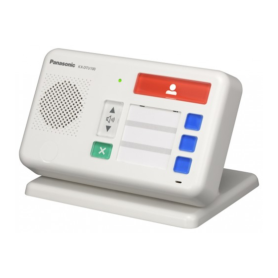
3 Location of Controls 3 Location of Controls ① Call Button (Flexible Button 1) Used to perform calls to caregivers. ② One Touch Button 1 (Flexible Button 3) ③ One Touch Button 2 (Flexible Button 4) ④ One Touch Button 3 (Flexible Button 5) Perform the functions assigned to the respective Flexible Buttons as One Touch Buttons. - Page 7 3 Location of Controls ⑨ Pin Jack Cover Used to cover the Pin Jack hole when the Pin Jack is not in use. ⑩ Speaker Used for hands-free talking and for listening to recorded messages. ⑪ Status LED Used to confirm the status of the unit. When the unit is in use, the Status LED turns off.
-
Page 8: Feature Operations
Before operating this unit, initial setup of the PBX is necessary. For more information about how to setup the PBX settings, please refer to the PBX manuals or contact your dealer. Manuals and support information are provided on the Panasonic Web site at: https://panasonic.net/cns/pcc/support/pbx/ 4.1 Making a call Pressing the Call Button ( This operation will make a call. - Page 9 4.2 Playback messages For example, it is convenient to register a telephone number of relevant peoples or facilities. (Home, caregivers, family members, etc.) Note In order to operate in this way, proper PBX settings are needed. However depending on the PBX settings, different operation is also possible. For details, consult your system administrator.
- Page 10 4.4 Terminate currently running feature Disconnected by the Called Party If the called party hangs up the phone, the conversation will be terminated and the unit will enter standby status without pressing the Cancel Button. A reorder tone may be heard from the speaker. Press the Cancel Button at that time, then the reorder tone will stop and the unit will enter standby status.
-
Page 11: Led Indications
5 LED Indications 5 LED Indications The status of the unit is indicated by the condition of the two LEDs shown in the table below: ① Status LED ② Call Button LED Status (Green) (White) Out of service (OUS) In Service (INS) ON ⇒... -
Page 12: Installation And Setup
6 Installation and Setup 6 Installation and Setup Note • Panasonic assumes no responsibility for injuries or property damage resulting from failures arising out of improper installation or operation inconsistent with this documentation. Attaching the Stand Main unit Stand ① Holes for the hook mounting (4 points) ②... - Page 13 6 Installation and Setup Removing the Stand Gently slide up the unit until the stand hooks will be released from the holes of the unit with both hands as shown. Remove the unit from the stand carefully.
- Page 14 6 Installation and Setup Connections Basic Connection for Wall Mounting Use two clamps TO PABX TO TEL TO MAIN UNIT Use clamps Connect to: a pull switch unit Connect to: a digital proprietary telephone Digital XDP connection Connect to a PBX. The telephone line cord...
- Page 15 6 Installation and Setup Note When this unit will be installed on a telephone wall plate or a gang box, using any clamps are subject to change for smooth running of the cables. Connection for the Stand Installation Connect the telephone line cords and the Pull switch cable as shown below Not use clamps Use upper clamp only...
- Page 16 6 Installation and Setup Attach the stand to the unit. Then hook the telephone line cords into the clamps as shown below.
- Page 17 6 Installation and Setup Connecting a Push Switch unit Before using, remove the Pin Jack Cover. Note To avoid accidental ingestion, place it out of reach of children. When the Push Switch cable Pin Jack Cover plug is not connected to the Pin Jack, make sure the Pin Jack is covered by the Pin Jack Cover for protection.
- Page 18 6 Installation and Setup Connecting a Pull Switch unit Use a flathead screwdriver to press and hold open the button below the terminal, and insert a pair of wire coming from the Pull Switch into the terminal. 2 pin terminal (Non polar) Stripped end of the wire 6 mm...
- Page 19 Note • When connecting a Push Switch unit Technical information about the Push Switch units that have been tested with this unit is provided on the Panasonic Web site at: https://panasonic.net/cns/pcc/support/pbx/ • When connecting a Pull Switch unit A cable used to connect a pull switch to the 2 pin connector must be less than 50 m (164 ft) in length.
-
Page 20: Wall Mounting
7 Wall Mounting 7 Wall Mounting Connect the cables to the unit and run the cables as shown in the illustration below. Drive the screws into the wall either 83 mm (3 1/4 in) or 100 mm (3 15/16 in) apart, and mount the unit on the wall. - Page 21 7 Wall Mounting WALL MOUNTING TEMPLATE One screw here 1. Drive the screws into the wall as indicated. 2. Hook the unit onto the screw heads. 3. Make sure that the unit is attached to the wall without wobbling. One screw at either point...
- Page 22 Note...
- Page 23 Note...
- Page 24 PNQX8308YA PM0916XM1037...