Table of Contents
Advertisement
Quick Links
Download this manual
See also:
Instruction Manual
Advertisement
Table of Contents

Related Manuals for Hitachi DV-P543U


Summary of Contents for Hitachi DV-P543U
-
Page 1: Dvd Player
No. 0422E DV-P543U SERVICE MANUAL DO NOT RESELL OR DIVERT IMPROPERLY. SPECIFICATIONS AND PARTS ARE SUBJECT TO CHANGE FOR IMPROVEMENT DVD PLAYER September 2004 Digital Media Division, Tokai... -
Page 2: Table Of Contents
CONTENTS 1 CAUTIONS FOR SAFETY IN PERFORMING 6 APPENDIX ......6-1 REPAIR ....... .1-1 6-1 SYSTEM CONTROL TIMING CHARTS . -
Page 3: Repair
CAUTION FOR SAFETY IN PERFORMING REPAIR 1-1 LASER BEAM SAFETY PRECAUTIONS This DVD player uses a pickup that emits a laser beam. Do not look directly at the laser beam coming from the pickup or allow it to strike against your skin. -
Page 4: Important Safety Precautions
1-2 IMPORTANT SAFETY PRECAUTIONS 1-2-1 Product Safety Notice I. Also check areas surrounding repaired locations. J. Be careful that foreign objects (screws, solder Some electrical and mechanical parts have special droplets, etc.) do not remain inside the set. safety-related characteristics which are often not evi- K. -
Page 5: Safety Check After Servicing
1-2-3 Safety Check after Servicing Examine the area surrounding the repaired location for damage or deterioration. Observe that screws, parts, Chassis or Secondary Conductor and wires have been returned to their original posi- tions. Afterwards, do the following tests and confirm the specified values to verify compliance with safety Primary Circuit Terminals standards. -
Page 6: Standard Notes For Servicing
1-3 STANDARD NOTES FOR SERVICING 1-3-1 Circuit Board Indications 1-3-4 Instructions for Handling Semi-conductors a. The output pin of the 3 pin Regulator ICs is indi- cated as shown. Electrostatic breakdown of the semi-conductors may occur due to a potential difference caused by electro- static charge during unpacking or repair work. -
Page 7: General Information
GENERAL INFORMATION 2-1 SPECIFICATIONS ITEM DESCRIPTION Output signal format NTSC color 75 Ω Video output impedance Video output level 1.0 V P-P Audio output level 2.0 Vrms Video S/N ratio 60 dB or more Disc used DVD video disc, Music CD disc DVD section DVD (linear audio) 20 Hz - 22 kHz (48 kHz sampling frequency) -
Page 8: Comparison Of Models
2-2 COMPARISON OF MODELS O: Yes, ---: No, : Same as on left ITEM DV-P543U DV-P533U Dimensional 435(W) x 50(H) x 211(D) mm 435(W) x 55(H) x 211(D) mm Hot Stamp Ultra Vision Badge Drive Speed Laser DVD/VCD/SVCD/CD-DA O / --- / --- / O... - Page 9 ITEM DV-P543U DV-P533U Disc Navigation DVD Zoom x2 / x4 / x16 O / O / --- Program and Random Play of DVD / A-B Repeat Repeat Resume O (can not effect after Power off) Closed Caption for NTSC DVD...
-
Page 10: Comparison Of Main Control Ics
2-3 COMPARISON OF MAIN CONTROL ICS ---: No, : Same as on left ITEM DV-P543U DV-P533U NC7SB3157P6X / SN74LVC1G3157DCKR NC7SB3157P6X (IC201) (IC201) OP AMP LM324PWR / LM324PT (IC202) KIA324F-EL (IC202) SERVO DRIVE SA5694 / FAN8024CDTF / BA5954FP-E2 / SA5694 / BA5954FP-E2 (IC301) -
Page 11: For Dvd Player
2-4 LIST OF ABBREVIATIONS AND TERMS FOR DVD PLAYER Index Abbreviation/Term Explanation See Dolby AC3. CD-R One type of DVD standard disc, to which writing once is possible (recordable type) CD-RW One type of CD standard disc, to which writing up to 1000 times is possible Component video Used for outputs of HDTV video signal format. -
Page 12: Operating Controls And Functions
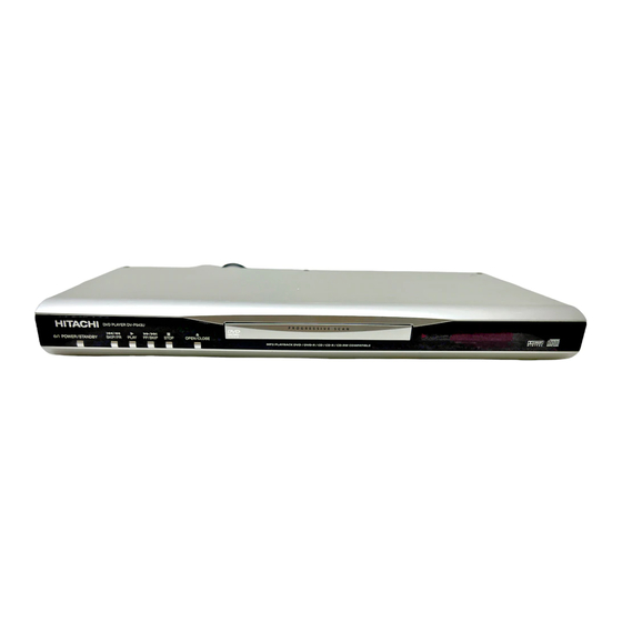
2-5 OPERATING CONTROLS AND FUNCTIONS FRONT PANEL 3 4 5 REAR VIEW /I (POWER/STANDBY) 9. MAIN (AC Power Cord) Connect to a standard AC outlet Switch the player to ON or OFF 10. COAXIAL (Digital audio out) (As to the indication of the Operate switch, “I” indicates ON and “... - Page 13 RETURN time. 9. DISC NAVIGATION Press to display the first scenes of each chapter of the title being played. HITACHI 10. PLAY DV-RM543U Press to begin playback. Press to view the DVD picture in fast reverse motion or to reverse playback of an Audio CD.
-
Page 14: Maintenance And Inspection
MAINTENANCE AND INSPECTION 3-1 TROUBLESHOOTING Troubleshooting is how to service for the specifying malfunction or poor parts. Detect malfunction or poor parts and service as the following charts. FLOW CHART NO.1 The power cannot be turned on. Is the fuse normal? See FLOW CHART No.2 <The fuse blows out.>... - Page 15 FLOW CHART NO.6 P-ON+10V (EV+11V) is not outputted. Check D1030, D1048, C1035, C1048, L1009 and Is 11V voltage supplied to the emitter of Q1002? the periphery circuit, and service it if defective. Check Q1016 and PWRCON line and service it if Is the voltage of base on Q1002 lower than the defective.
- Page 16 FLOW CHART NO.11 The fluorescent display tube does not light up. Is 3.3V voltage supplied to Pins(6,24) of IC2001? Check the EV+3.3V line and service it if defective. Is the voltage of approximately -20V supplied to Check the -FL (-20V) line and service it if defective. Pin(15) of IC2001? Is there 500kHz oscillation at Pin(26) of IC2001? Check R2002, IC2001 and their periphery, and...
- Page 17 FLOW CHART NO.14 The disc tray cannot be opened and closed. (It can be done using the remote control unit.) Is the normal control voltage inputted to Pin(4) of Replace the "OPEN/CLOSE" button (SW2108). IC2001? Refer to "FLOW CHART NO.12" <The key operation is not functioning.>...
- Page 18 FLOW CHART NO.19 Both functions of picture and sound do not operate normally. Replace the DVD Main CBA. No improvement can be found. Original DVD Main CBA is poor. Replace the DVD Mecha. FLOW CHART NO.20 Picture does not appear normally. Set the disc on the disc tray, and playback.
- Page 19 FLOW CHART NO.21 Audio is not outputted normally. Set the disc on the disc tray, and playback. Replace the DVD Main CBA or DVD Mecha. Are the analog audio signals outputted to each pin of CN1601 on AV CBA? CN1601 14PIN AUDIO-L CN1601 16PIN AUDIO-R Check each line between each pin of CN1601 Are the analog audio signals inputted to each pin...
-
Page 20: Firmware Renewal Mode
3-2 FIRMWARE RENEWAL MODE 3-2-1 How to Update the Firmware Ver- The appearance shown in (*1) of Fig. c is described as follows: sion Note: Appearance State If the firmware has been changed, etc., we will use Reading... Sending files into the memory Service News, etc. -
Page 21: How To Verify The Firmware Version
10.Press [CLEAR] button on the remote control unit. Fig. h appears on the screen. " ******* " differ depending on the models. MODEL : ******* Version : *.** Region : * EEPROM CLEAR : OK EEPROM CLEAR : CLEAR EXIT: POWER Fig. -
Page 22: Disassembly
DISASSEMBLY 4-1 CABINET DISASSEMBLY INSTRUCTIONS 4-1-1 Disassembly Flowchart About tightening screws When tightening screws, tighten them with the follow- This flowchart indicates the disassembly steps to gain ing torque. access to item(s) to be serviced. When reassembling, follow the steps in reverse order. Bend, route, and Screws Torque dress the cables as they were originally. - Page 23 (S-2) [1] Top Case (S-1) [3] Reinforce Plate Fig. D1 Fig. D3 (S-3A) (L-1) FCC Cover (S-3B) CN201 (L-3) CN601 CN301 CN401 [4] DVD Main (L-1) CBA Unit (L-2) [2] Front Assembly Fig. D2 Short the three short lands by soldering. (Either of two places.) Connector View for A...
- Page 24 [7] Function CBA [5] DVD Mecha (S-4) [6] AV CBA (S-4) (S-5) CN2001 (S-4) (S-6) (L-4) Fig. D5 Fig. D6 HOW TO EJECT MANUALLY (Method 1) 1. Remove the Top Case. 2. Remove the Reinforce Plate. 3. Rotate the roulette in the direction of the arrow as shown below.
- Page 25 HOW TO EJECT MANUALLY (Method 2) 1. Turn the unit over. 2. Insert the shaft less than a diameter of 3 mm (e.g. screw- driver) straightly into the opening as shown. 3. Turn the shaft along with the opening clockwise. View for B 4.
-
Page 26: Exploded View And Parts List
EXPLODED VIEW AND PARTS LIST 5-1 EXPLODED VIEW Note: Components without any numbers in exploded views had not been assigned as service parts 3 X 10 as of the date of issue of this manual. 3 X 10 M3 X 8 3 X 10 M3 X 8 3 X 11... -
Page 27: Replacement Parts List
5-2 REPLACEMENT PARTS LIST Note: Products marked with a # have special characteristics important to safety. 5-2-1 Mechanical Parts List SYMBOL-NO P-NO DESCRIPTION SYMBOL-NO P-NO DESCRIPTION MECHANISM SECTION TJ17571 PANEL,FRONT TJ16981 FOOT,REAR TJ17572 CASE,TOP # AC1001 TE15463 CORD,AC TJ17573 DVD DRIVE MECHA TJ17579 HOLDER TJ17574... -
Page 28: Electrical Parts List
Note: Although some parts in the schematic diagrams have different names from those in 5-2-2 Electrical Parts List the parts list, there is no problem in replacing parts. SYMBOL-NO P-NO DESCRIPTION SYMBOL-NO P-NO DESCRIPTION Q1352 TC10778 TRANSISTOR KTC3199 SEMI-CONDUCTORS TRANSFORMER D1001 TC10752 DIODE 1A5... -
Page 29: Appendix
APPENDIX 6-1 SYSTEM CONTROL TIMING CHARTS Tray Close ~ Play / Play ~ Tray Open Tray Disc Disc Tray Play Close Rotation Stop Open 3.3V Tray IN (TL221) Sled Drive 1.65V (TP303) 1.65V Disc Drive (TP301) 1.65V Focus Drive (TP304) Tracking Drive 1.65V (TP302) -
Page 30: Ic Pin Function Descriptions
6-2 IC PIN FUNCTION DESCRIPTIONS IC2001 [ FIP DRIVER ] Signal Name Function Name FP-CLK Clock Input FP-STB Serial Interface Strobe Key Data 1 Input Key Data 2 Input Power Supply a / KEY-1 Segment Output / Key Source-1 Segment Output / Key b / Key-2 Source-2 Segment Output / Key... -
Page 31: Lead Identifications
6-3 LEAD IDENTIFICATIONS 2SC2785(H) 2SA1015-Y(TPE2) 2SK3498 BN1L3Z(P) 2SC2120-Y(TPE2) KRA110M KTA1266(Y) KTA1267(Y) KTC3198(Y) KTC3199(GR) KTC3203(Y) G D S E C B E C B KIA4558P FAN431AZXA MM1636XWRE NJM4558D PT6313-S-TP KIA431-AT RC4580IP SC16313 K A R EL817B EL817C PQ070XZ5MZP MM1637XVBE LTV-817B-F LTV-817C-F PS2561A-1(Q,W) 1: Vin 2: Vc... -
Page 32: Sschematic, Wiring Diagrams
SCHEMATIC, WIRING DIAGRAMS S-1 Schematic Diagrams / CBA’s and Test Points Standard Notes Notes: 1. Do not use the part number shown on these draw- WARNING ings for ordering. The correct part number is shown Many electrical and mechanical parts in this chassis in the parts list, and may be slightly different or have special characteristics. - Page 33 LIST OF CAUTION, NOTES, AND SYMBOLS USED IN THE SCHEMATIC DIAGRAMS ON THE FOLLOWING PAGES: 1. CAUTION: For continued protection against fire hazard, replace only with the same type fuse. ê ATTENTION: Pour une protection continue les risqes d'Incele n'utiliser que des fusible de m type.
-
Page 34: Wiring Diagram
S-2 Wiring Diagram DIGITAL AUDIO OUT VIDEO-Y VIDEO-Cb/Pb VIDEO-Cr/Pr VIDEO AUDIO-L AUDIO-R S-VIDEO AC CORD COAXIAL CN2001 CN2101 AV CBA KEY-2 FUNCTION CBA KEY-3 KEY-1 KEY-4 CN2101 is soldered directly to the PCB. CN1001 CN1601 (CN1001 is soldered directly to the PCB.) (CN1601 is soldered directly to the PCB.) CN401 CN601... -
Page 35: Dvd Main 1/3 Schematic Diagram
S-3 DVD Main 1/3 Schematic Diagram... -
Page 36: Dvd Main 2/3 Schematic Diagram
S-4 DVD Main 2/3 Schematic Diagram... - Page 37 IC101 VOLTAGE CHART ~ : Voltage is not consistent ----- : Not used Unit : Volts PIN.NO PLAY STOP PIN.NO PLAY STOP PIN.NO PLAY STOP PIN.NO PLAY STOP PIN.NO PLAY STOP PIN.NO PLAY STOP PIN.NO PLAY STOP PIN.NO PLAY STOP ----- ----- -----...
-
Page 38: Dvd Main 3/3 Schematic Diagram
S-5 DVD Main 3/3 Schematic Diagram... -
Page 39: Av 1/3 Schematic Diagram
S-6 AV 1/3 Schematic Diagram CAUTION ! CAUTION ! For continued protection against fire hazard, NOTE : Fixed voltage ( or Auto voltage selectable ) power supply circuit is used in this unit. replace only with the same type fuse. The voltage for parts in hot circuit is measured If Main Fuse (F1001) is blown, check to see that all components in the power supply ATTENTION : Pour une protection continue les risqes... -
Page 40: Av 2/3 Schematic Diagram
S-7 AV 2/3 Schematic Diagram... -
Page 41: Av 3/3 & Function Schematic Diagram
S-8 AV 3/3 & Function Schematic Diagram FL2001 MATRIX CHART SACD REPEAT TITLE GROUP PSCAN SACD PSCAN REPEAT HD VCD GROUP TITLE S-10... -
Page 42: Waveforms
S-9 Waveforms Pin 8 of CN1601 Pin 16 of CN1601 VIDEO-Y VIDEO-Y 0.2V 0.2V 20µs AUDIO-R AUDIO-R 0.5ms 0.5ms Pin 10 of CN1601 Pin 19 of CN1601 VIDEO-C VIDEO-C 0.2V 0.2V 20µs SPDIF SPDIF 0.1µs C1402 PLUS LEAD NOTE: Input CD: 1kHz PLAY (WF4~WF6) DVD: POWER ON (STOP) MODE... -
Page 43: Ccircuit Board Diagrams
CIRCUIT BOARD DIAGRAMS C-1 AV CBA Top View CAUTION ! CAUTION ! For continued protection against fire hazard, Fixed voltage ( or Auto voltage selectable ) power supply circuit is used in this unit. replace only with the same type fuse. If Main Fuse (F1001) is blown, check to see that all components in the power supply ATTENTION : Pour une protection continue les risqes NOTE :... -
Page 44: Av Cba Bottom View
C-2 AV CBA Bottom View CAUTION ! CAUTION ! For continued protection against fire hazard, Fixed voltage ( or Auto voltage selectable ) power supply circuit is used in this unit. replace only with the same type fuse. If Main Fuse (F1001) is blown, check to see that all components in the power supply ATTENTION : Pour une protection continue les risqes circuit are not defective before you connect the AC plug to the AC power supply. -
Page 45: Function Cba Top/Bottom View
C-3 Function CBA Top/Bottom View FUNCTION CBA Top View FUNCTION CBA Bottom View... -
Page 46: Bblock Diagrams
BLOCK DIAGRAMS B-1 System Control / Servo Block Diagram... -
Page 47: Digital Signal Process Block Diagram
B-2 Digital Signal Process Block Diagram... -
Page 48: Video/Audio Block Diagram
B-3 Video / Audio Block Diagram... -
Page 49: Power Supply Block Diagram
B-4 Power Supply Block Diagram... - Page 50 No. 0422E Digital Media Division, Tokai DV-P543U...