Panasonic PT-D3500U Service Manual
Hide thumbs
Also See for PT-D3500U:
- Operating instructions manual (72 pages) ,
- Brochure & specs (4 pages) ,
- Limited warranty (1 page)

Related Manuals for Panasonic PT-D3500U


Summary of Contents for Panasonic PT-D3500U
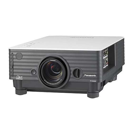
- Page 1 ORDER NO. VED0507366C0 DLP™ Based Projector PT-D3500U PT-D3500E © 2005 Matsushita Electric Industrial Co., Ltd. All rights reserved. Unauthorized copying distribution is a violation of law.
- Page 2 PT-D3500U / PT-D3500E...
-
Page 3: Table Of Contents
PT-D3500U / PT-D3500E CONTENTS Page Page 1 Safety Precautions 11.7. Removal of Ballast Module 1.1. General Guidelines 11.8. Removal of R-P.C.Board 1.2. Leakage Current Check 11.9. Removal of Projection Lens 2 Specifications 11.10. Removal of Lamp Unit 3 Function for Safety 11.11. -
Page 4: Safety Precautions
PT-D3500U / PT-D3500E cord in a power outlet. 1 Safety Precautions 3. Connect M1 to T1 according to Fig. 2 and measure the voltage. 1.1. General Guidelines 4. Change the connection of M1 from T1 to T2 and measure · For continued safety, no modification of any circuit must be the voltage again. -
Page 5: Specifications
PT-D3500U / PT-D3500E 2 Specifications... - Page 6 PT-D3500U / PT-D3500E...
-
Page 7: Function For Safety
PT-D3500U / PT-D3500E 3 Function for Safety 3.1. Interlock Switch To ensure safety, the protection circuit of the main unit functions, and this projector becomes operation halt condition (a part of circuit is energizing) when the lamp unit cover is opened or installed incorrectly. -
Page 8: Resetting To User Mode
PT-D3500U / PT-D3500E Set the operation mode selector (Computer/Numeric, Projector) switch to “Projector” on the remote control unit and press the ENTER button. Press the MENU button. Note: · "SERVICEMAN" will appear. 4.2. Resetting to User Mode Press the MENU button. -
Page 9: Functions In Serviceman Mode
PT-D3500U / PT-D3500E 4.3. Functions in Serviceman Mode 4.3.1. EXT OPTION "EXT OPTION" is added to the MENU. 1. CUT OFF Sets the display ON/OFF for each color (R, G, B). 2. SELF CHECK Displays SELF CHECK. There are 2 pages, and it is switched with... - Page 10 PT-D3500U / PT-D3500E [1st page]...
- Page 11 PT-D3500U / PT-D3500E [2nd page] 3. CW INDEX When the color wheel is replaced, adjusts it with buttons. Select DYNAMIC in PICTURE MODE, and execute it according to the following procedure with the red gradation (test pattern a. Decrease CW INDEX setting value from the default value (431) by 50, and set it to 381.
- Page 12 PT-D3500U / PT-D3500E * The label that describes the alphabet is pasted on the DMD. 4.3.2. SUB-KEYSTONE "SUB-KEYSTONE" is added to KEYSTONE in the "POSITION" menu. If KEYSTONE and "Lens shift" are used at the same time, the right and left is corrected in the unbalance.
- Page 13 PT-D3500U / PT-D3500E...
-
Page 14: Using The Serial Terminals
PT-D3500U / PT-D3500E 5 Using the Serial Terminals SERIAL terminals which are on the side-mounted connection terminals conform to RS-232C standard. This projector can be controlled by a PC which is connected as shown below. 5.1. Examples of Connection 5.2. -
Page 15: Procedure Of Communication Condition Settings
PT-D3500U / PT-D3500E Attention · No command can be sent or received for 10 to 60 seconds after the lamp starts lighting. Try sending any command after that period has elapsed. · When sending several commands, be sure to wait for a response from the projector before sending the next command. - Page 16 PT-D3500U / PT-D3500E Items Commands:Parameters Functions Callback Remarks ENTER ENTER key CURSOR UP key DOWN key LEFT key RIGHT key STANDARD STANDARD key AUTO SETUP AUTO SETUP execution SHUTTER OSH:0 SHUTTER key OSH:0 Calls back ER402 when 0=OFF 1=ON SHUTTER of REMOTE2 is ON.
-
Page 17: Inquiry Commands
PT-D3500U / PT-D3500E Items Commands:Parameters Functions Callback Remarks SUB MEMORY OCS:p1p2 SUB MEMORY switching OCS:p1p2 p1p2: 00, 01, 02, 03, . . . 07, 08 Sets 00 when the sub memory is not used. ENTRY SUB OES:p1p2 Enters current receiving signal into the OES:p1p2 P1p2: 01, 02, 03, . - Page 18 PT-D3500U / PT-D3500E Items Commands:Para Functions Callback Interpretati Remarks meters TV-SYSTEM Inquiry about TV-SYSTEM AUTO1 AUTO2 NTSC NTSC4.43 N-PAL M-PAL SECAM PAL60 Black and white 50 Black and white 60 POSITION Inquiry about horizontal position p1p2p3p4 Inquiry about vertical position...
-
Page 19: Cable Specifications
PT-D3500U / PT-D3500E Items Commands:Para Functions Callback Interpretati Remarks meters GET SYSTEM Inquiry about the system (lamp) status Lamp off STATUS In turning Lamp on In turning (cooling) VOLUME Inquiry about VOLUME p1p2p3 000 - 063 MUTE Inquiry about MUTE... -
Page 20: Setting The Projector Id Number Remote Control
PT-D3500U / PT-D3500E 6 Setting the Projector ID Number Remote Control Every projector has its ID number and the ID number of the controlling projector must be set to the remote control in advance so that the user can operate the remote control. The ID number of the projector is set to “ALL” on shipping, and use the ID ALL button of the remote control when using only a single projector. -
Page 21: Support For Service
PT-D3500U / PT-D3500E 7 Support for Service 7.1. Supporting Methods We will support according to the following methods. Supporting methods Applied parts Replaced by module or block FM-Module (For specified components, supplies them discretely.) Ballast module Power module (PB-Module) PA-Module... -
Page 22: Parts Location
PT-D3500U / PT-D3500E 9 Parts Location 9.1. Electrical Parts Location 9.2. Electromechanical Parts Location... -
Page 23: Replacement Of Lamp Unit
PT-D3500U / PT-D3500E 10 Replacement of Lamp Unit Cautions · Wait until the lamp is cooled sufficiently before replacing the lamp unit. 10.1. Precautions on Lamp Unit Replacement Remove the power plug and confirm that the surroundings of the lamp unit have cooled off. -
Page 24: Indication Of Lamp Monitor
PT-D3500U / PT-D3500E 10.3. Indication of Lamp Monitor 10.4. Procedure of Lamp Unit Replacement NOTE: · Be sure to follow steps 8 to 13 in ten minutes after turning on the projector because the projector is turned off in ten minutes... - Page 25 PT-D3500U / PT-D3500E...
- Page 26 PT-D3500U / PT-D3500E...
-
Page 27: Disassembly Instructions
PT-D3500U / PT-D3500E 11 Disassembly Instructions 11.1. Flowchart for Disassembly To assemble, reverse the disassembly procedures. -
Page 28: Removal Of Top Cover
PT-D3500U / PT-D3500E 11.2. Removal of Top cover Unscrew the 6 screws on the side. Lift the top cover and remove it. 1. Pull the upper part of the lens hole of the lower case a little forward and disconnect the front hook. -
Page 29: Removal Of J-P.c.board
PT-D3500U / PT-D3500E Pull out the flexible cable connected to the J-P.C.Board. (The reverse side of A-P.C.Board) Unscrew the 9 screws and remove the A-P.C.Board. Unscrew the 2 screws and remove the operation button. 11.4. Removal of J-P.C.Board Remove the A-P.C.Board block according to the steps 1 through 5 in the section 11.3. -
Page 30: Removal Of Pb-Module
PT-D3500U / PT-D3500E 11.6. Removal of PB-Module Remove the lamp unit according to the section 11.10. "Removal of Lamp Unit". Remove the top cover according to the section 11.2. "Removal of Top cover". Unscrew the 1 screw and remove the grounding terminal. -
Page 31: Removal Of Ballast Module
PT-D3500U / PT-D3500E Remove the PB-Module. 11.7. Removal of Ballast Module Remove the PB-Module according to the section 11.6. "Removal of PB-Module". Unscrew the 2 screws and remove the lamp unit terminal. Unscrew the 1 screw and remove the ballast module block. -
Page 32: Removal Of R-P.c.board
PT-D3500U / PT-D3500E 11.8. Removal of R-P.C.Board Remove the top cover according to the section 11.2. "Removal of Top cover". Unscrew the 1 screw and remove the R-P.C.Board. 11.9. Removal of Projection Lens Fully turn the projection Lens counterclockwise. Turn the projection lens counterclockwise in addition while pressing the lens lock button. -
Page 33: Removal Of Optical Block
PT-D3500U / PT-D3500E Loosen the 2 screws fixing the lamp unit until they idle, hold the handles and take the lamp unit out. Note: When installing the lamp unit (or a new one) in the main unit, place it in a specified position and press the right and left sides of the lamp unit, and confirm the lamp unit is inserted securely. - Page 34 PT-D3500U / PT-D3500E Unscrew the 2 screws and remove the lamp duct. Unscrew the 1 screw and remove the thermofuse attachment. Loosen the 1 screw until it idles, then open the lamp unit cover. Loosen the 2 screws fixing the lamp unit until they idle, hold the...
-
Page 35: Removal Of Dmd Block And Lighting Block
PT-D3500U / PT-D3500E Remove the projection lens 1. Fully turn the projection Lens counterclockwise. 2. Turn the projection lens counterclockwise in addition while pressing the lens lock button. 3. Remove the projection lens. Unscrew the 8 screws and remove the optical block. -
Page 36: Removal Of Color Wheel Block (Lighting Block)
PT-D3500U / PT-D3500E 11.13. Removal of Color Wheel Block (Lighting Block) Remove the A-P.C.Board block according to the steps 1 through 5 in the section 11.3. "Removal of A-P.C.Board". Unscrew the 5 screws and remove the lighting case (upper). Disconnect flexible cable from/to the color wheel block. - Page 37 PT-D3500U / PT-D3500E Unscrew the 1 screw and remove the mechanical shutter motor unit.
-
Page 38: Troubleshooting
PT-D3500U / PT-D3500E 12 Troubleshooting The alphabets (A, FM, etc.) in the left box of the inspection items indicate the names of P.C.Boards or modules to be checked. - Page 39 PT-D3500U / PT-D3500E...
- Page 40 PT-D3500U / PT-D3500E...
- Page 41 PT-D3500U / PT-D3500E...
- Page 42 PT-D3500U / PT-D3500E...
- Page 43 PT-D3500U / PT-D3500E...
- Page 44 PT-D3500U / PT-D3500E...
- Page 45 PT-D3500U / PT-D3500E...
- Page 46 PT-D3500U / PT-D3500E...
- Page 47 PT-D3500U / PT-D3500E...
- Page 48 PT-D3500U / PT-D3500E...
-
Page 49: Interconnection Block Diagram
PT-D3500U / PT-D3500E 13 Interconnection Block Diagram 13.1. Interconnection Block Diagram (1/3) Interconnection Block Diagram (1/3) A-P.C.Board J-P.C.Board T-P.C.Board... - Page 50 PT-D3500U / PT-D3500E 13.2. Interconnection Block Diagram (2/3) Interconnection Block Diagram (2/3) CW-P.C.Board A-P.C.Board FM-Module R-P.C.Board...
-
Page 51: Interconnection Block Diagram
PT-D3500U / PT-D3500E 13.3. Interconnection Block Diagram (3/3) Interconnection Block Diagram (3/3) Ballast PA-Module Module PB-Module... - Page 52 PT-D3500U / PT-D3500E...
-
Page 53: Block Diagram
PT-D3500U / PT-D3500E 14 Block Diagram 14.1. Power Supply Power Supply THERMOFUSE PA1 PB1 FUSE F101 LINE DC380V Power FACTOR Igniter RECTIFIER Lamp+ FILTER CORRECTION Transformer Lamp- Power Cord PA-Module Low Voltage Current Voltage Control Detector Detector Power Supply From A-P.C.Board A5... -
Page 54: Signal Processing
PT-D3500U / PT-D3500E 14.2. Signal Processing (1/2) Signal Processing (1/2) IC3003 DVI-D RECEIVER DDCSCL IC3034 IC3035 DDCSDA SDRAM EDID EDID RESIZE / SCALER IC3025 IC3007 RGB2 IC3015 IC3006 IC3631 RGB A/D HSYNC ANALOG CONVERTER SWITCH SDRAM RGB1 IC3629 IC3014 IC3017... -
Page 55: Signal Processing (2/2)
PT-D3500U / PT-D3500E 14.3. Signal Processing (2/2) Signal Processing (2/2) IC4004 IC4006 A-P.C.Board FM-Module R-P.C.Board FLASH RDRAM MEMORY IC3049 (REAR) IC4001 IC4002 IC4008 (FPGA) LVDS DMD DRIVE VIDEO SIGNAL PROCESSOR, 0.7 inch RECEIVER PROCESSOR SYNC SIGNAL PROCESSOR, XGA DDR TEST PATTEN GENERATOR... -
Page 56: Fan/Motor Drive
PT-D3500U / PT-D3500E 14.4. Fan/Motor Drive Fan/Motor Drive HIGH CONTRAST LENS SHIFT ZOOM/FOCUS APERTURE A-P.C.Board IC3635 IC3627 IC3628 ZOOM1 ZOOM/ ZOOM2 LENS SHIFT LENS SHIFT IRIS FOCUS LIMITER DRIVER FOCUS1 DRIVER DRIVER FOCUS2 IC3625 REGULATOR IC2502, IC2503 33SCL7 Q3605, Q3606... -
Page 57: Schematic Diagram
PT-D3500U / PT-D3500E 15 Schematic Diagram... -
Page 58: A-P.c.board
PT-D3500U / PT-D3500E 15.1. A-P.C.Board (1/11) A-P.C.Board TXN/A2VKA3 (1/11) MAIN... -
Page 59: A-P.c.board
PT-D3500U / PT-D3500E 15.2. A-P.C.Board (2/11) A-P.C.Board TXN/A2VKA3 (2/11) MAIN... -
Page 60: A-P.c.board
PT-D3500U / PT-D3500E 15.3. A-P.C.Board (3/11) A-P.C.Board TXN/A2VKA3 (3/11) MAIN... -
Page 61: A-P.c.board
PT-D3500U / PT-D3500E 15.4. A-P.C.Board (4/11) A-P.C.Board TXN/A2VKA3 (4/11) MAIN... -
Page 62: A-P.c.board
PT-D3500U / PT-D3500E 15.5. A-P.C.Board (5/11) A-P.C.Board TXN/A2VKA3 (5/11) MICON... -
Page 63: A-P.c.board
PT-D3500U / PT-D3500E 15.6. A-P.C.Board (6/11) A-P.C.Board TXN/A2VKA3 (6/11) MICON... - Page 64 PT-D3500U / PT-D3500E 15.7. A-P.C.Board (7/11) A-P.C.Board TXN/A2VKA3 (7/11) MICON...
- Page 65 PT-D3500U / PT-D3500E 15.8. A-P.C.Board (8/11) A-P.C.Board TXN/A2VKA3 (8/11)
- Page 66 PT-D3500U / PT-D3500E 15.9. A-P.C.Board (9/11) A-P.C.Board TXN/A2VKA3 (9/11) GC3I...
- Page 67 PT-D3500U / PT-D3500E 15.10. A-P.C.Board (10/11) A-P.C.Board TXN/A2VKA3 (10/11) NETWORK...
- Page 68 PT-D3500U / PT-D3500E 15.11. A-P.C.Board (11/11) A-P.C.Board TXN/A2VKA3 (11/11) NETWORK...
-
Page 69: Cw/R/T-P.c.board
PT-D3500U / PT-D3500E 15.12. CW/R/T-P.C.Board CW-P.C.Board TXNCW1VKA3 R-P.C.Board TXN/R1VKA3 T-P.C.Board TXN/T1VKA3... -
Page 70: J-P.c.board
PT-D3500U / PT-D3500E 15.13. J-P.C.Board (1/2) J-P.C.Board TXN/J1VKA3 (1/2) -
Page 71: J-P.c.board (2/2)
PT-D3500U / PT-D3500E 15.14. J-P.C.Board (2/2) J-P.C.Board TXN/J1VKA3 (2/2) - Page 72 PT-D3500U / PT-D3500E...
-
Page 73: Circuit Boards
PT-D3500U / PT-D3500E 16 Circuit Boards 16.1. A-P.C.Board (Foil Side) A-P.C.Board TXN/A2VKA3 (Foil side) A-P.C.Board (Foil Side) IC2002 IC3020 IC2006 IC3025 IC2009 IC3034 IC2502 IC3035 IC2503 IC3038 IC2505 IC3049 IC2507 IC3601 IC2508 IC3614 IC2509 IC3623 IC2519 IC3628 IC2522 IC3629 IC3008... -
Page 74: A-P.c.board (Component Side)
PT-D3500U / PT-D3500E 16.2. A-P.C.Board (Component Side) A-P.C.Board TXN/A2VKA3 (Component side) A-P.C.Board (Component Side) IC2001 IC3012 IC2004 IC3014 IC2007 IC3015 IC2008 IC3017 IC2011 IC3018 IC2501 IC3026 IC2506 IC3036 IC2511 IC3040 IC2515 IC3043 IC2516 IC3045 IC2517 IC3046 IC2523 IC3608 IC2524 IC3612... -
Page 75: J-P.c.board
PT-D3500U / PT-D3500E 16.3. J-P.C.Board J-P.C.Board TXN/J1VKA3 (Foil side) J-P.C.Board TXN/J1VKA3 (Component side) J-P.C.Board (Component Side) IC9801 IC9802 IC9803 IC9804 IC9805 IC9806 IC9807 IC9808 IC9809 IC9810 TRANSISTOR Q9801 Q9802 Q9803 Q9804 Q9805 Q9806 Q9807 Q9808 Q9809 Q9810 Q9811 Q9812 ADDRESS INFORMATION... - Page 76 PT-D3500U / PT-D3500E...
-
Page 77: Terminal Guide Of Ics And Transistors
PT-D3500U / PT-D3500E 17 Terminal guide of ICs and transistors... -
Page 78: Exploded Views
PT-D3500U / PT-D3500E 18 Exploded Views... - Page 79 PT-D3500U / PT-D3500E...
- Page 80 PT-D3500U / PT-D3500E...
-
Page 81: Replacement Parts List
PT-D3500U / PT-D3500E 19 Replacement Parts List Ref. Part No. Part Name & Remarks Ref. Part No. Part Name & Remarks Description Description TKKC5194 REMOTE CONTROL RECEIVER [MECHANICAL PARTS] TKKC5220 LED PLATE TKKL5244-1 LENS CAP D4CDH4930004 THERMISTER(OPTICAL) TKNE053 FILTER D4CDH5030003... - Page 82 PT-D3500U / PT-D3500E Ref. Part No. Part Name & Remarks Ref. Part No. Part Name & Remarks Description Description TSK1018 FERRITE CORE IC2007 C0EBB0000145 J0KG00000013 IC2008 C0DBFFD00003 TSXL474 FLEX CABLE (A3-J1) IC2009 C2DBMY000001 TSXL475 FLEX CABLE(A41-FM1) IC2011 C0CBCBF00005 TSXL477 FLEX CABLE(A-CW)
- Page 83 PT-D3500U / PT-D3500E Ref. Part No. Part Name & Remarks Ref. Part No. Part Name & Remarks Description Description IC9810 C1BB00001099 D2004 MA157A DIODE MA3X157A D2005 LNJ308G8TRA [TRANSISTORS] D2007 LNJ308G8TRA D2008 LNJ308G8TRA Q2001 UNR221100L TRANSISTOR D2501 LNJ308G8TRA Q2501 UNR221100L TRANSISTOR...
- Page 84 PT-D3500U / PT-D3500E Ref. Part No. Part Name & Remarks Ref. Part No. Part Name & Remarks Description Description L3628 J0JHC0000078 FILTER [COILS] L3629 J0JHC0000078 FILTER L3632 ELJFA470JFB COIL L2001 J0JHC0000078 FILTER L3633 ELJFA270JFB COIL L2002 J0JHC0000078 FILTER L3634 ELJFA270JFB...
- Page 85 PT-D3500U / PT-D3500E Ref. Part No. Part Name & Remarks Ref. Part No. Part Name & Remarks Description Description FL3008 J0HABC000011 FILTER R2070 D1HG2208A002 RESISTOR FL3019 J0HABB000021 FILTER R2075 ERJ3GEYJ220 M 22 OHM,J,1/16W FL3020 J0HABB000021 FILTER R2076 ERJ3GEYJ220 M 22 OHM,J,1/16W...
- Page 86 PT-D3500U / PT-D3500E Ref. Part No. Part Name & Remarks Ref. Part No. Part Name & Remarks Description Description R2205 ERJ3GEY0R00 M 0 OHM, 1/16W R2571 EXB28V103J RESISTOR ARRAY R2220 ERJ3GEYJ471 M 470 OHM,J,1/16W R2572 ERJ3GEY0R00 M 0 OHM, 1/16W...
- Page 87 PT-D3500U / PT-D3500E Ref. Part No. Part Name & Remarks Ref. Part No. Part Name & Remarks Description Description R2713 ERJ3GEYJ184V RESISTOR R3104 EXB28V220J RESISTOR ARRAY R2714 ERJ3GEYJ105 M 1M OHM,J,1/16W R3105 D1HG2208A002 RESISTOR R2717 ERJ3GEYJ220 M 22 OHM,J,1/16W R3106...
- Page 88 PT-D3500U / PT-D3500E Ref. Part No. Part Name & Remarks Ref. Part No. Part Name & Remarks Description Description R3183 ERJ3EKF2200 M 220 OHM, 1/16W R3259 D1HG2208A002 RESISTOR R3184 ERJ6GEYJ560 M 56 OHM,J,1/10W R3260 ERJ3GEYJ220 M 22 OHM,J,1/16W R3185 ERJ3GEYJ473...
- Page 89 PT-D3500U / PT-D3500E Ref. Part No. Part Name & Remarks Ref. Part No. Part Name & Remarks Description Description R3750 ERJ3GEYJ562 M 5.6KOHM,J,1/16W R9813 ERJ3GEYJ102 M 1K OHM,J,1/16W R3752 ERJ6ENF2001 M 2KOHM, 1/10W R9814 ERJ3GEYJ154 M 150 OHM,J,1/16W R3753 ERJ6ENF1501V...
- Page 90 PT-D3500U / PT-D3500E Ref. Part No. Part Name & Remarks Ref. Part No. Part Name & Remarks Description Description C2011 ECJ1VF1C104Z C 0.1UF, Z, 16V C2519 ECJ1VF1C104Z C 0.1UF, Z, 16V C2012 ECJ1VF1C104Z C 0.1UF, Z, 16V C2520 ECJ1VF1C104Z C 0.1UF, Z, 16V...
- Page 91 PT-D3500U / PT-D3500E Ref. Part No. Part Name & Remarks Ref. Part No. Part Name & Remarks Description Description C3032 ECJ1VF1C104Z C 0.1UF, Z, 16V C3112 ECJ1VF1C104Z C 0.1UF, Z, 16V C3033 ECJ1VF1C104Z C 0.1UF, Z, 16V C3113 ECJ1VF1C104Z C 0.1UF, Z, 16V...
- Page 92 PT-D3500U / PT-D3500E Ref. Part No. Part Name & Remarks Ref. Part No. Part Name & Remarks Description Description C3187 ECJ1VF1C104Z C 0.1UF, Z, 16V C3680 ECJ1VB1H103K C 0.01UF, K, 50V C3188 ECJ1VF1C104Z C 0.1UF, Z, 16V C3681 ECJ1VC1H101J C 100PF, J, 50V...
- Page 93 PT-D3500U / PT-D3500E Ref. Part No. Part Name & Remarks Ref. Part No. Part Name & Remarks Description Description C3781 F2G1E4R70007 CAPACITOR K1KA03AA0104 3P CONNECTOR C3785 F2G0J4700010 CAPACITOR K1KA04BA0014 4P CONNECTOR C3788 EEEHB0G101R E 100UF, 4V K1KA08BA0047 8P CONNECTOR C3790...