Table of Contents
Advertisement
Quick Links
SERVICE MANUAL
Ver 1.0 2003.07
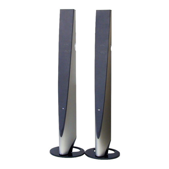
SA-VF700ED is front speaker system in SA-VS700ED.
For the U.S. model
AUDIO POWER SPECIFICATIONS
POWER OUTPUT AND TOTAL HARMONIC
DISTORTION:
With 3 ohms loads both subwoofer driven, from 20 - 200 Hz; rated 250
watts minimum RMS power, with no more than 0.8% total harmonic
distortion from 250 milliwatts to rated output.
SA-VF700ED
Speaker system
2 way and built-in subwoofer
Speaker units Subwoofer:
11 cm (4
Woofer: 8 cm (3
Tweeter: 2.5 cm (1 in.), dome type
Enclosure type
Bass reflex
Rated impedance
8 ohms
Power handling capacity
Maximum input power:
170 watts
Sensitivity level
88 dB (1 W, 1 m)
Frequency range
20 Hz - 70,000 Hz
Inputs
LINE IN: input pin jack
SPEAKER IN: speaker cord
Sony Corporation
9-961-024-01
2003G02-1
Home Audio Company
© 2003.07
Published by Sony Engineering Corporation
SA-VF700ED
SPECIFICATIONS
3
/
in.), cone type
8
1
/
in.), cone type
4
HOME THEATER SPEAKER SYSTEM
General
Power requirements
US, CND model:120 V AC, 60 Hz
AEP, UK model :220 -230 V AC, 50/60 Hz
Power consumptions
250 W
1 W (standby mode)
Dimensions (w/h/d)
Approx. 300 x 1,200 x 300 mm
(11
Mass
AMP SIDE: Approx. 16.7 kg
(36 lb 13.07 oz)
NON AMP SIDE: Approx. 15.0 kg
(33 lb 1.11 oz)
Supplied accessories
Audio connecting cord, 5 m (16 ft
1
Subwoofer connecting cord, 5m (16 ft
Speaker connecting cords, 5 m (16 ft
Design and specifications are subject to change without notice.
US Model
Canadian Model
AEP Model
UK Model
7
1
7
/
x 47
/
x 11
/
in.)
8
4
8
/
in.) (1)
2
1
/
in.) (1)
2
1
/
in.) (2)
2
Advertisement
Table of Contents

Related Manuals for Sony SA-VF700ED


Summary of Contents for Sony SA-VF700ED
-
Page 1: Specifications
SA-VF700ED SERVICE MANUAL US Model Canadian Model Ver 1.0 2003.07 AEP Model UK Model SA-VF700ED is front speaker system in SA-VS700ED. SPECIFICATIONS For the U.S. model General AUDIO POWER SPECIFICATIONS Power requirements US, CND model:120 V AC, 60 Hz POWER OUTPUT AND TOTAL HARMONIC... -
Page 2: Table Of Contents
SONY PARTS WHOSE PART NUMBERS APPEAR AS FONCTIONNEMENT. NE REMPLACER CES COMPOSANTS SHOWN IN THIS MANUAL OR IN SUPPLEMENTS PUB- QUE PAR DES PIÈCES SONY DONT LES NUMÉROS SONT LISHED BY SONY. DONNÉS DANS CE MANUEL OU DANS LES SUPPLÉMENTS... -
Page 3: General
SA-VF700ED SECTION 1 GENERAL This section is extracted from instruction manual. • Location of controls BOOST PHASE POWER SAVE SW LEVEL BOOST PHASE POWER SAVE INPUT SELECTOR NORM AUTO SW IN SUB WOOFER IN REVERSE SPEAKER IN POWER SW LEVEL... -
Page 4: Service Position For Control Board
SA-VF700ED 2-2. SERVICE POSITION FOR CONTROL BOARD Control board Bottom (L) ASSY Five screws Bottom (L) ASSY Control board 2-3. WIRE STOPPER Primary side of the power supply Wire stopper Secure the wires not to touch the primary side of the power supply. -
Page 5: Disassembly
SA-VF700ED SECTION 3 DISASSEMBLY Be careful not to break the tweeter cone, because it is so thin. Ring ASSY, Grill frame (front) ASSY Bottom section Subwoofer (SP103) Note : Follow the disassembly procedure in the numerical order given. 3-1. RING ASSY, GRILL FRAME (FRONT) ASSY... -
Page 6: Bottom Section
SA-VF700ED 3-2. BOTTOM SECTION Speaker cabinet 1 Two screws (+BVTP 4 x14) Base (front) Speaker cabinet 3 Bottom section... -
Page 7: Subwoofer (Sp103)
SA-VF700ED 3-3. SUBWOOFER (SP103) 1 Pick up speaker with pliers Subwoofer (SP103) Priers Subwoofer (SP103) 2 Pick up the both sides of speaker Continued on next page... - Page 8 SA-VF700ED 3 Turn its face backward. Subwoofer (SP103) Subwoofer (SP103) 4 Find the direction of woofer unit not to touch the cabinet by turning it. Subwoofer (SP103) Fasten terminal 5 Set it to the direction the fasten terminal is on the side and take it out of cabinet.
-
Page 9: Diagrams
SA-VF700ED SECTION 4 DIAGRAMS THIS NOTE IS COMMON FOR PRINTED WIRING BOARDS AND SCHEMATIC DIAGRAMS. (In addition to this, the necessary note is printed in each block.) For Schematic Diagrams. Note: For Printed Wiring Boards. Note : • All capacitors are in µF unless otherwise noted. pF: µµF 50 WV or less are not indicated except for electrolytics and tantalums. -
Page 10: Schematic Diagram - Control Section
SA-VF700ED 4-2. SCHEMATIC DIAGRAM – CONTROL SECTION – (Page 14) (Page 14) -
Page 11: Printed Wiring Boards - Control Section
SA-VF700ED 4-3. PRINTED WIRING BOARDS – CONTROL SECTION – See page 9 for Circuit Boards Location. Semiconductor CONTROL BOARD Location Ref. No. Location D101 D102 D103 D104 D105 D106 L-CH D207 ATTENUATOR D208 D209 D210 D211 POWER D330 BOARD D331... -
Page 12: Schematic Diagram - Power Section
SA-VF700ED 4-4. SCHEMATIC DIAGRAM – POWER SECTION – (Page 12) (Page 12) -
Page 13: Printed Wiring Boards - Power Section (Side A)
SA-VF700ED 4-5. PRINTED WIRING BOARDS – POWER SECTION (SIDE A) – See page 9 for Circuit Boards Location. POWER BOARD (SIDE A) 1-689-587- (11) -
Page 14: Printed Wiring Boards - Power Section (Side B)
SA-VF700ED PRINTED WIRING BOARDS – POWER SECTION (SIDE B) – See page 9 for Circuit Boards Location. ICE250A-SW CONTROL BOARD (Page 13) (SIDE B) POWER BOARD T902 POWER TRANSFORMER Semiconductor Location Ref. No. Location D201 D202 D203 D204 D205 D206... -
Page 15: Exploded Views
SA-VF700ED SECTION 5 EXPLODED VIEWS NOTE : • The mechanical parts with no reference number in the • -XX, -X mean standardized parts, so they exploded views are not supplied. may have some difference from the original The components identified by •... -
Page 16: Speaker Section L-Ch
SA-VF700ED 5-2. SPEAKER SECTION L-CH SP103 supplied supplied SP104 supplied SP101 not supplied SP102 not supplied Ref. No. Part No. Description Remark Ref. No. Part No. Description Remark X-4955-918-1 FRAME (FRONT) ASSY, GRILL (US,CND) SP103 1-825-557-11 SPEAKER (11cm) X-4955-982-1 FRAME (FRONT) ASSY, GRILL (AEP,UK) SP104 1-825-558-11 SPEAKER (2.5cm) -
Page 17: Bottom Section L-Ch
SA-VF700ED 5-3. BOTTOM SECTION L-CH supplied supplied supplied supplied Ref. No. Part No. Description Remark Ref. No. Part No. Description Remark A-4747-845-A CONTROL BOARD, COMPLETE 4-250-008-01 LENS A-4747-846-A POWER BOARD, COMPLETE (AEP,UK) 1-689-580-11 AC S/W BOARD A-4747-864-A POWER BOARD, COMPLETE (US,CND) -
Page 18: Bottom Section R-Ch
SA-VF700ED 5-4. BOTTOM SECTION R-CH Speaker section (R-ch) supplied supplied Ref. No. Part No. Description Remark Ref. No. Part No. Description Remark 4-250-024-01 BOTTOM (R) 4-250-005-01 FOOT (FRONT) 4-250-007-01 CUSHION (BOTTOM) 7-685-662-79 SCREW +BVTP 4X14 TYPE2 N-S 4-250-004-01 BASE (FRONT) -
Page 19: Speaker Section R-Ch
SA-VF700ED 5-5. SPEAKER SECTION R-CH SP903 supplied SP904 supplied SP901 supplied supplied SP902 supplied Ref. No. Part No. Description Remark Ref. No. Part No. Description Remark X-4955-918-1 FRAME (FRONT) ASSY, GRILL (US,CND) SP903 1-825-557-11 SPEAKER (11cm) X-4955-982-1 FRAME (FRONT) ASSY, GRILL (AEP,UK) SP904 1-825-558-11 SPEAKER (2.5cm) -
Page 20: Electrical Parts List
SA-VF700ED SECTION 6 AC S/W CONTROL ELECTRICAL PARTS LIST NOTE : • Items marked “ * ”are not stocked since they • Due to standardization, replacements in the are seldom required for routine service. Some parts list may be different from the parts... - Page 21 SA-VF700ED CONTROL JACK POWER Ref. No. Part No. Description Remark Ref. No. Part No. Description Remark < TRANSISTOR > R307 1-249-429-11 CARBON 1/4W R308 1-249-421-11 CARBON 2.2K 1/4W F Q101 8-729-029-86 TRANSISTOR DTC124ESA R309 1-249-435-11 CARBON 1/4W Q102 8-729-119-76 TRANSISTOR 2SA1175-HFE...
- Page 22 SA-VF700ED POWER Ref. No. Part No. Description Remark Ref. No. Part No. Description Remark 0 C911 1-165-706-91 FILM 0.01uF 630V D807 8-719-991-33 DIODE 1SS133T-77 C912 1-126-947-11 ELECT 47uF 0 D901 8-719-022-92 DIODE RBV-604 (US,CND) 0 D901 C913 1-162-290-31 CERAMIC 470PF...
- Page 23 SA-VF700ED POWER SELECT VOL CONTROL Ref. No. Part No. Description Remark Ref. No. Part No. Description Remark < TRANSISTOR > 1-689-583-11 SELECT BOARD *********** Q201 8-729-036-89 TRANSISTOR KTC3198GR-A Q202 8-729-037-02 TRANSISTOR KTA1266Y-AT 4-248-894-01 KNOB (SELECT) Q701 8-729-029-86 TRANSISTOR DTC124ESA Q703 8-729-178-42 TRANSISTOR 2SC2784-F <...
-
Page 24: Revision History
SA-VF700ED REVISION HISTORY Clicking the version allows you to jump to the revised page. Also, clicking the version at the upper right on the revised page allows you to jump to the next revised page. Ver. Date Description of Revision...